1. Introduction
In recent years, both industrialized and developing nations have shown a great deal of interest in the use of unmanned aerial vehicles (UAVs) for environmental protection, emergency assistance, catastrophe monitoring, border surveillance, and rescue missions [
1]. Drones were initially only utilized in military activities [
2]. However, research academia and industries in a variety of sectors such as filmmaking, news broadcasting, civil application, and various rescuing services regarding disaster management have been putting a lot of emphasis to the features of UAVs, such as building aerial communication networks, small volume, mobility, low overhead communication, monitoring, and scanning [
3,
4,
5]. UAVs can easily and effectively obtain awareness of situations on the ground. Even in locations without network infrastructure, UAVs can provide surveillance [
4]. Quality of service (QoS) provisioning in UAV-assisted communication is a difficult study topic in aerial ad hoc network systems [
6,
7]. When a natural disaster (damaging a large area) such as an earthquake, flood, or storm occurs, multi-UAVs are used to complete a complex mission. Multi-UAVs are launched, execute some operations to gather proof of the presence of disaster victims, and then communicate the acquired data to the base station or the ground rescue team. In a crisis scenario, the primary goal of this paper is to assist the rescue team in rescuing victims. In order to achieve maximum protection of the victims by leveraging UAVs technology, the drone integration pilot project has been launched in the USA [
8].
Disaster is a terrible problem, either natural or artificial, for any country. A minor delay in a disaster leads to the loss of many precious lives. Natural disasters, such as hydrological, meteorological geophysical, hydrological, and climatological, always cause tremendous unpredictable loss of life and damage to property. In the post-disaster phase, whenever a disaster occurs, it damages large areas due to not identifying the total affected area. In a disaster scenario, it is a very difficult task for the rescue team to provide rescue services; as well as it identifying the populated area in a disaster, it is also hard for rescue teams to reach there on time without knowing the condition of the area. On the other hand, UAVs having a flying nature, fast strong mobility, low communication overhead, small volume, communication technology, and computing capabilities also mean that they are a suitable alternative candidate to play an important role in times of disaster. Their scanning capabilities help in identifying the affected area and their monitoring capabilities also provide and show the live condition of the area [
9].
The efficient and fastest awareness of disaster scenarios can easily be achieved by UAVs. Single UAVs often fail to fulfill the requirements of complicated missions because the disaster may occur on a large scale. The multi-UAVs communication system played an effective role in addressing the above issues. UAVs’ communication is effective in such scenarios where the multi-UAVs and various models are used for communication, as well as to avoid collision between the UAVs [
10]. Identifying the exact location of the victim at the time of disaster can be carried out proficiently by the UAVs. Scanning the area through UAVs and detecting any user equipment capable of aerial communication, tracing the location, and providing communication on the spot can be carried out by UAVs [
11].
Our goal in this work is to provide a useful scanning and rescue technique. Recent research can also be divided into three categories. In the first layer, certain studies are primarily concerned with the deployment of UAVs in dangerous areas in order to maximize drone connectivity and forge solid connections. To maximize network connectivity, they primarily concentrate on UAVs’ network topology. However, they did not take into account the ground user equipment. They exclusively concentrate on creating protocols that can accommodate the UAV network’s primary requirements, which include high mobility, dynamic topology, intermittent connectivity, power limits, and variable link quality. Second, many studies concentrated on UAV applications that either tracked or targeted ground equipment, but the UAVs lacked cooperation since they employed sensors to detect their target ground user equipment before tracking it. However, no consideration is given to UAVs and target equipment communicating. Researchers in the third category concentrated on the ground or aerial base station that serves the user equipment that is located on the ground. The base station connects to and manages UAVs. The UAVs’ ability to communicate with one another is not taken into account. For controlling and deploying UAVs in disaster or afflicted areas, multiple controllers are also deployed at once. A controller can connect the UAVs’ network to other networks and communicate with at least one UAV to transfer control packets.
In this research, we proposed a communication protocol called intelligent cluster-based multi-unmanned aerial vehicle (ICBM-UAV) to get beyond the aforementioned restrictions. The ICBM-UAV protocol has three different modes of communication; base station (BS) comes first, followed by user equipment (UE), then drone (UAV). For an effective survey of the ground and detection of the user equipment, a protocol scenario where there is a significant number of user equipment in the ground was taken into consideration. The suggested work is separated into two sections: first, the scanning part, in which a UAV scans the area and marks or identifies the precise location of the smart devices; second, the part in which base station information is provided; the last section offers communication through UAVs throughout the entire damage area. One CH (cluster head) is made up of an average of every five drones in the proposed protocol, which allows for effective communication.
The remainder of this paper is organized as follows.
Section 2 introduces the literature review of a different model of the UAV-based search and rescue model in various situations. In
Section 3, the proposed algorithm and the hovering positions for the UAVs based on different creation of cluster searching strategies are described.
Section 4 presented the simulation results, and
Section 5 concludes the paper.
2. Literature Review
This section reviews the literature works on the deployment of UAVs and maximizes the coverage of the UAVs’ network. Furthermore, the extensive literature provides the study of the various proposed methodology used for the deployment of drones, maximizing the coverage, and the various techniques used for identifying the object (car, user equipment, etc.) on the ground.
Minaeian S et al. [
2] developed a system for UAVs to assist the SAR mission after the occurrence of a disaster. In one single flight, the UAV system acquits the geo-information and searches information with the help of various sensors. They present an algorithm for target identification with the ability of self-adapting threshold.
Alotaibi ET et al. [
3] had discussed various strategies for searching based on the greedy heuristic, partially observable decision process, and potential-based algorithm to design the control of several UAVs. They make sure to extract as much information as they can from the search activity. Barritt et al. [
9] discussed the aerial network communication application based on SDN communication to the direct user and connectivity of backhaul. Scientia et al. [
10] proposed architecture of SDN-based UAV network using multiple radio technologies such as LET and IEEE 802.11. Zhao et al. [
11] discussed the caching-based mechanism work that showed how UAVs worked cooperatively with the base stations helping in the delivery of video in the dense networks. The UAVs and base station deliver and store the content at an off-peak time, reducing the backhaul pressure.
Cheng et al. [
12] proposed the scheme-optimizing trajectory of unmanned aerial vehicles by providing various adjacent base stations for offloading data. An iterative algorithm is also proposed for solving the problem by optimizing the edge user scheduling.
Rosario et al. [
13] proposed their work by providing a UAV relay service to transmit high-quality live streaming. Ming Chen et al. [
14] suggested a flocking model for UAVs based on biological studies, which assisted in avoiding collisions. The proposed flocking model employs highly intelligent, autonomous UAVs with real-time UAV control. The flocking algorithm is implemented using commercial equipment, and Wi-Fi-based positioning and communication is suggested for the UAV flocking network. They proposed a distributed flocking strategy in which UAVs use a boids model [
15] to autonomously change their position. UAVs may detect adjacent flight information and modify their position within a specific range. They also exhibit separation, cohesion, and alignment behaviors. The follower must adjust autonomously depending on the pertinent received information, according to the distributed flocking model; the essential idea of the DFM is that when the follower is too close to the leader, it should fly away from it. When the follower is far away, it should fly toward the leader. When the distance between the leader and the follower changes, the follower must keep the same pace and distance from the leader. Cohesiveness can be avoided by adhering to these guidelines.
Jin Chen et al. [
16] proposed a multi-UAV coverage deployment model based on the energy-efficient network communication in UAVs. Energy is the major problem in the UAVs; addressing this problem, their model was introduced, which is further divided into two steps coverage maximization and power control: both proved EPG (exact potential game) and NE (Nash equilibrium) point. The deployment of an energy-efficient algorithm can guarantee coverage maximization and power control.
H. Duan [
17] proposed the game-theoretic approach for multi-unmanned aerial vehicle searching and surveillance cooperatively and formulated the constrained set of actions for vehicles for preparation of deployment calculation. From the game-theoretic, the interaction of multi-UAVs can be studied effectively, which helps in providing the theoretical support for relevant methods optimized in UAV networks.
Boyang Li et al. [
18] designed and implemented the relay control protocol. They created ground station control software to help with the relay system. They ran the test in two scenarios: inside and outdoor. Their effort was primarily focused on delivering communication relays via a single drone (node). Zhan et al. [
19] discussed the work based on the algorithm that helped relay the network base station and the ground terminals. These works help in optimizing the relay system performance. Cetin et al. [
20] proposed the novel dynamic approach for maintaining the communication for vehicles in long-range relay communication infrastructure. The artificial potential was their base for path planning.
Guo et al. [
21] analyzed the use of UAVs for providing relay services for cellular networks. The throughput and ping of the upload and download were tested in both the rural and urban environments. Haitao Zhao et al. [
22] developed two techniques for distinct scenarios in their work: centralized deployment and dispersed motion. The information of the UE on the ground is already known in a centralized algorithm, which aids in the deployment of the minimum number of UAVs in that area, whereas in a distributed algorithm, the UAVs take flight toward the area on demand, control their motion, and also find the UE on run time, which aids in the on-demand coverage problem. However, in both instances, the algorithm is designed to keep the UAV networks connected.
The two network techniques presented by Haole Chen et al. [
23] are for maximizing communication and network efficiency. They employ the greedy method to locate the hovering spot in the area. They separated the global optimization problem into sub problems, and the solution to each subgroup problem was derived using the range determination approach. Multiple UAVs may collaborate to build a UAV network (UAVNet) to execute tasks more efficiently and economically than a single UAV.
J. Yoon et al. [
24] proposed a method to gather the information of the network from the air about delay-sensitive data. In the context of UAVs’ usage, some recent studies have designed optimal path planning using a UAVs. Arzamendia et al. [
25] aimed to solve a traveling salesman problem for environmental monitoring based on a genetic algorithm that calculated fitness functions to maximize coverage. Devaurs et al. [
26] conducted substantial research on the problem of path planning and space exploration. Although most of them were designed to reduce duplicate coverage across agents, they cannot be immediately transferred to the UAV context because networking capability and lightweight computation are not taken into account. Through their ad hoc deployment, UAVs can be employed as suitable communication resources to quickly rejoin separated networks. UAVs can help to solve the network hole problem by acting as temporary relay nodes [
20,
21].
Zhang et al. [
27] proposed using an unmanned surface vehicle (USV) and an UAV to provide rescue services in a flooded area. The USV transports the UAVs to the spot, obtains information, and assists the survivors. USV is in charge of gathering environmental information using a laser and a camera, and with such capabilities, USV can generate a map and provide rescue materials to catastrophe victims. The combination of USV with UAVs allows the USV to obtain general area information for path planning while also being capable of designing a local path using its local information.
In [
28], focused on network and communication technologies that can aid drone disaster management and early warning systems, SAR operations, data collection, and emergency communication and network provision. Their report also investigated network technologies that play a crucial role in drone deployment during disaster management. The author also discusses the design and difficulties (antenna structure, drone cooperation, path planning, channel modelling disaster areas, and energy efficiency).
Yanmaz et al. [
29] presented a cooperative air-borne system of unmanned aerial vehicles (UAVs) with high-level architecture to test their capabilities in disaster SAR operations and aerial surveillance. In addition, the author discusses certain crucial aspects in the UAV network system (sensing, coordination, and communication modules). The primary goal of the research was to support and assist firefighters in times of catastrophe, to give real-time video streaming, and to expand coverage capabilities to support the SAR mission.
M. Erdelj et al. [
30] proposed forecasting, response, and evaluation of inland flooding systems. The proposed architecture enables multi-UAV dependability and security, as well as a UAV remote control system for usage with the smart cell and UAV infrastructure on-demand. Matias et al. proposed a flying real-time network (FRTN) [
31] for connecting the field’s deployed static and mobile devices via flying units. Given the time constraints, the proposed network sends signals from the field to the incident commander and from the incident commander to the field. They also talk about digital communication in SAR missions using UAVs during the initial reaction to natural disasters.
In [
32], Ruetten et al. proposed a search and rescue scheme by using a genetic algorithm for the UAV swarm. For optimizing the coverage area, UAVs are capable of a self-organizing mesh network. The communication strength of connected UAVs is constantly checked through RSSI, and UAVs adjust their position close to neighbor UAVs when the strength is lower than the threshold. The scheme is capable of maintaining group communication while moving together for searching.
In [
3], Alotaibi et al. proposed a technique focusing on achieving SAR missions in minimum time while rescuing the maximum disaster victims. The authors simulate the proposed work in a real scenario task distribution among UAV. They compared their proposed work with bio-inspired in the real scenario regarding the number of victims rescued with limited execution time for performance evaluation.
M.Rahmes et al. tackled the marine SAR mission problem employing cognitive and autonomous UAVs in their suggested work [
33]. To enable the cognitive multi-UAVs and achieve their goal, they used cooperative game theory and a computer on board with the victim’s last spotted location. In [
34], extending the wireless coverage of the UAV unified framework of a UAV-assisted emergency network is reported based on the multi-hop ground device to device communication. In [
35] serving the ground user, UAVs and the BS cooperatively introduced non-orthogonal multiple access.
Muhammad Asif et al. presented a UAV-aided Wi-Fi direct network design in [
36]. They suggested an effective approach for optimal UAV deployment and decreasing GO and client device distance. The planned effort focuses on keeping devices connected and enhancing network speed. The suggested system has a flaw in that it does not address UAV coordination and trajectory optimization to avoid collisions.
In [
37], Malandrino et al. discussed improving wireless network coverage in disasters by replacing the traditional yet affected communication with a UAV network. They also present the optimized range while maximizing the user throughput. In [
38], Erdelj et al. devised the IoT UAV ecosystem for providing real-time data (multimedia) communication in affected-communication environments with the help of multi-UAVs. Additionally, this also offers on-demand usage of various available sensor mobile phone and UAV infrastructures. In [
39], Chen et al. proposed the usage of cache-enabled UAVs and provided the quality of experience to mobile word users using a cloud radio access network while minimizing and reducing the UAV transmitting power and transmission delay in the system. With the use of machine learning, centric-human information can be used to predict a user’s content distribution and mobility.
In [
40], Kim et al. propose a solution to create UAV-based network topology that is adjustable with the topological changes that occur due to the unpredictable mission-based movement of UAVs. For making topology adaptive, they use relay nodes named relay UAVs for relaying data between adjacent UAVs. This also supports reliable communication in-ground site wireless link and also maximizes the performance of a network. In the proposed particle swarm optimization (PSO), they considered dependency between metric and routing protocol. In [
41], an iterative algorithm is proposed to obtain the suboptimal solutions used to efficiently solve the power allocation sub problem. Reconfigurable intelligent surface (RIS) has been identified as a promising solution for constructing a reconfigurable radio environment of the propagation channel and increasing received signal power by smartly coordinating the phase shifts of the passive elements at the RIS [
42]. To properly group the multiple users into clusters, [
43] proposed a novel user pairing scheme in which more than two users are paired in each cluster based on channel correlation and channel gain difference.
We have examined the research carried out between 2012 and 2022. The literature review mentioned above came to the conclusion that a number of researchers have looked for and used UAVs in a disaster area. They prioritize UAV deployment and primarily expand the network’s coverage. In some research publications, the tracking of user equipment and UAV communication were studied. They have not, however, concentrated on the UAV’s limitations, such as battery life, communication range, and processing power. When deploying a UAV network, it is crucial to consider battery longevity; instead, they primarily concentrate on expanding UAV coverage. The majority of the researchers spend a lot of time on each drone or ground station performing computing work. To overcome the drawbacks of earlier work, a protocol for optimal UAV deployment is required. In this protocol, an effective UAV network employs the clustering technique to perform computation tasks, conserve battery life, and assist the ground team in searching for and locating missing people during rescue operations. Additionally, information gathered from the disaster region aids in pinpointing a stranded person’s specific location. Additionally, in a disaster area, the enabled communication services promptly alert trusted authorities.
3. Research Methodology
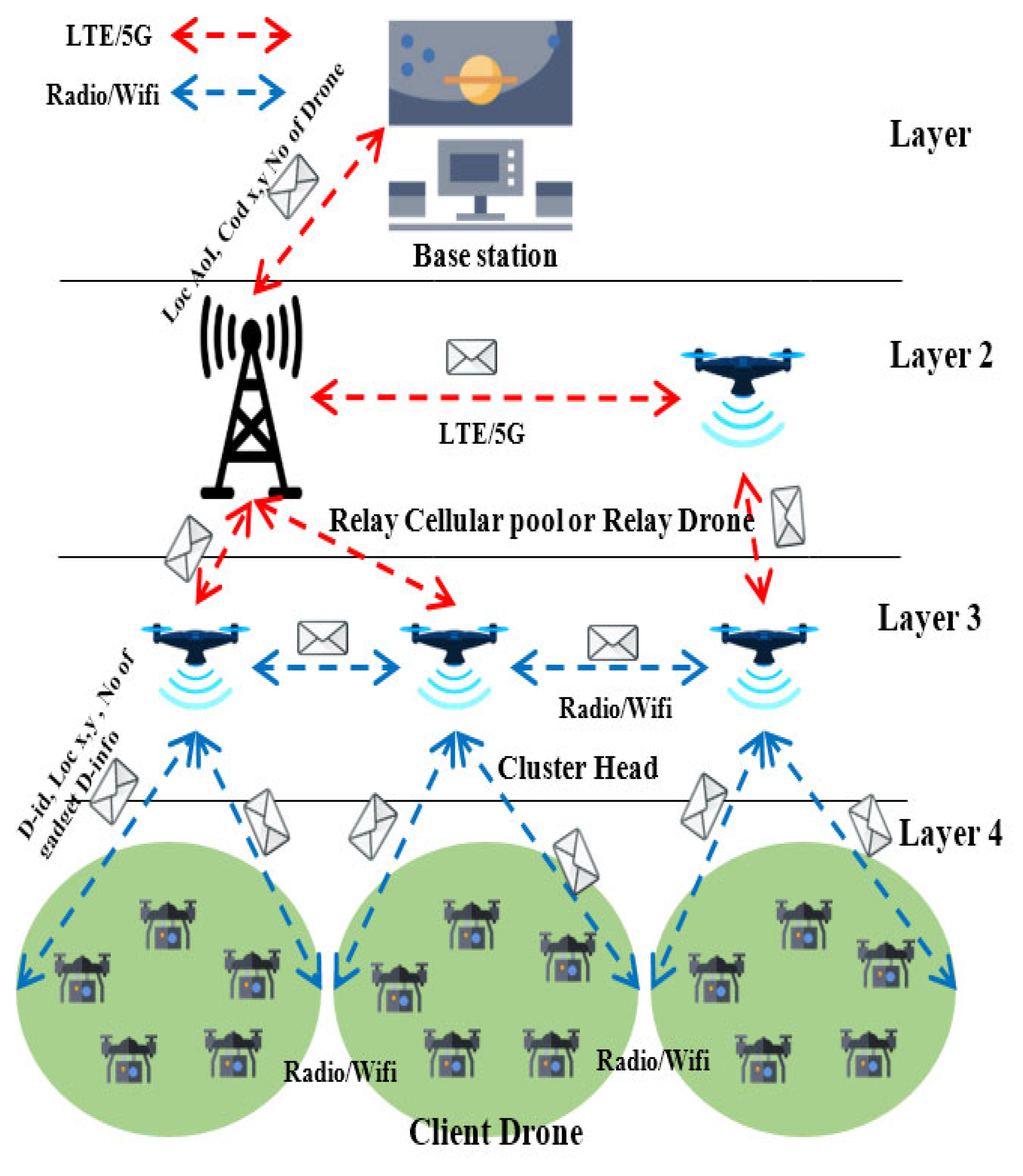
We developed a protocol called intelligent cluster-based multi-unmanned aerial vehicles (ICBM-UAVs). In an ICBM-UAV, where communication takes place at three levels. As depicted in
Figure 1, the base station (BS) comes first, followed by the drone (UAV), and finally user equipment (UE). All of the data collected from the disaster area were recorded by the BS. All of the data collected from the disaster area were stored by the BS. Additionally, ICBM-UAVs aid in updating the emergency and other security departments. UAVs play a big role in the network. They aid in locating the victims in a disaster region and determining the entire area that has been impacted. The drones’ ability to see victims in a disaster zone comes from UE. They are sophisticated devices with the ability to communicate in the air. In this context, we started by introducing the architecture that would ensure the efficient operation of our suggested routing protocol.
3.1. The Architecture of ICBM-UAV Protocol
The architecture of the ICBM-UAV is further divided into four layers. The first layer is the base station layer, the second layer is the relay layer, the third layer is known as the cluster layer, and the last layer is the client layer. Each layer has a specific task to perform. The first two layers use the cellular network for communication and data transfer; the other two layers use the radio or wireless connection between them for communication and data transfer. The working of each layer is as follow:
3.1.1. Base Station Layer
The base station is a central part that controls the flight of drones. This layer helps in storing all the gathered information and helps in the deployment of a drone in the disaster area. The base station collects all the data and also informs the other emergency department. It provides the location of the disaster area by sending the coordinates X and Y (cod x,y) toward the CHs, which is very helpful in the deployment of drone for communication layer 1 using the cellular network LTE/5G to enhance the security and operation of a drone, as shown in
Figure 2.
3.1.2. Relay Layer
The relay layer consists of a cellular pool and relay drone. The relay layer uses the LTE/5G technology to connect layer 1 with layer 2 and provides the relay for the drone that is far from the base station. The relay can be achieved by the cellular pool in case the cellular network or cellular pool is not available near the disaster area; then the relay drone will act as a relay to facilitates the drones and establish the connection between layer 1 and layer 3.
3.1.3. Cluster Layer
This layer covers the responsibility of controlling the constant number of drones. The CH contains all the information of their client drone (energy, movement, sensory information). Two types of communication will take place between CH to CH and CH to client drone. The drones’ communication with each other will takes place with the help of dedicated radio/wireless technology, as shown in
Figure 1.
3.1.4. Client Layer
The last layer is known as the client layer. This layer consists of a drone with a specially dedicated sensor, known as a target recognition sensor, used when the client drone flies over the UEs. These drones are controlled by the CH. They communicate with the CH using radio/wireless technology. They forward some parameters (such as D-id, UE cod x/y, d-energy, no of UE), and this information is forwarded to the CH.
3.2. Working on the Proposed Protocol
UAVs are divided into CH (CH) and client. CH always flies above the clients at a fixed height and controls the client. In this paper, the UE is a mobile phone, which used the aerial base backbone network to transmit information. The UE (Mobile) is spread over the ground because of terrain limitations. UAVs are considered to be equipped with omnidirectional antennas for transmitting and receiving signals in a highly mobile environment. There is more than one CH that provides stability and connection toward BS. Scanning and detecting the mobile in the disaster area is a major task in disaster times. After detecting and scanning the area, providing communication in the area is also important. The scanning area helps in providing the communication and deployment of communication drones. The work is divided into two parts, scanning of the area and providing communication in the area. In the scanning part, the detection and the calculating the total affected area are carried out. The providing of communication and monitoring of the area is achieved with the help of a Wi-Fi hotspot/antennas for providing communication toward ground users and a camera for monitoring the ground conditions.
(i). Part I: Scanning of Disaster Affected Area: Disaster causes loss of life. Disasters are classified as either natural disasters or artificial disasters. If a disaster happens, then one of the most important tasks is to scan the area, which helps in calculating the total affected area. Through scanning, the detection task will be performed. Afterward, the next step is hovering drones, in which the scanning of area and detection of UE are carried out; this step achieves the exact location of UE.
a. Hovering UAV: Unmanned aerial vehicles start flying from the base station (BS) toward the disaster area. The UAV is mainly divided into two categories, (i) CH (CH) and (ii) worker UAV (client). CH mainly focuses on the data gathering from its workers (client), data transferring and data filtering. By using a target recognition sensor, the client’s UAV hovers over the disaster region and detects the user equipment’s (UE) mobile capable connectivity. CH constantly forwards its location to the nearest CH to avoid redundancy of the data. UAV uses the flocking model, which has some desirable properties and helps UAVs in separation, alignment, cohesion, and obstacle avoidance. The algorithm of hovering UAVs is given in Algorithm 1. The algorithm shows the creation of the CH and the connectivity of UAV. The flow diagram of the CH of the hovering UAVs is shown in
Figure 3.
b. Environmental Hazards: During the flight, a drone should possess some properties, such as the ability to avoid obstacles (trees, buildings, etc.); obstacle avoidance is also important during UAV flight in order to avoid collision with other UAVs. We assume that the drone flies at some height and automatically avoids the obstacles in the disaster area.
| Algorithm 1: Creation of CH Algorithm. |
| Input Model: Disaster location |
| Output Model: Total damage area with No of UE. |
| Disaster Area ← UAV; Scanning← UAV; UAV ← Find UE (target recognition sensor) |
| if (UE ! = found && Disaster Area = true) ; Drop sensor and fly forward |
| if else (UE == Found || UE == connected) ; UE connected == yes ; Move forward |
| if else (UE ! = connected); UAV ← location (X,Y) UE; |
| Broadcast the CH Request; |
| If else (CH == found); Forward the information plus location, |
| else UAV ← CH; UAV broadcast client request; End if |
In Algorithm 1, every five drones have one CH, which is also known as the sleeping drone, as shown in
Figure 3. The CH provides communication, data transferring, and data mining. The sleeping drone (CH) comes to work whenever the power or battery of one drone is below the threshold, so the CH will replace it. Hovering drones contains dual power; they use solar power as well as batteries. In the daytime, the drones work on solar power, which gives them a longer life.
c. Cluster Head Flow Diagram: The drone will take a flight to provide communication and monitoring of the area. Furthermore, it helps in information gathering of the user equipment, which helps in rescuing the victims. The drone takes flight from a base station and hovers over the disaster area; once the drone detects the user equipment after the detection of user equipment, then the drone confirms if the user equipment is already detected or not if the UE is detected, then the drone flies toward next position. The drone requests for CH, and in the case that there is no CH, then the drone itself becomes CH, or if the drone finds the CH then it hands over its data to CH as, shown in
Figure 3.
In Algorithm 2, the UAV hovers over the disaster area; it is not stable at one fixed position, moving from one position to another. The hovering UAV changes its position for the discovering of UE in the disaster area. As the hovering UAV changes its position at some specific time for discovering the new UE, the optimal position is a must for the UAVs to avoid collisions between them and to avoid the redundancy of the data from the hovering drone.
| Algorithm 2: Client UAV algorithm |
| Input Model: CH and next position |
| Output Model: No of UE and location of UE |
| UAV ← Hovering Disaster area; CUAV ← Search UE. |
| If (UE == Yes & UE == connected); UAV ← Move next position; |
| If else (UE == Yes & UE ! = connected); UAV ← connect UE; UAV ← location UE |
| if else (UE ! = connected); UAV ← location (X,Y) UE; |
| UAV ← Move next position; End if |
(ii). Part II: Providing Communication in Area: After the allocation of UE is carried out in the scanning part, then the communication part will take place in this surveillance.
a. Surveillance UAV: Surveillance drone comes after the scanning using hovering drones. Now the exact location of the UE is known, so enough drones take flight toward the disaster area. These drones contain the following: (i) camera for video monitoring or live coverage, (ii) Wi-Fi communication capability, and (iii) solar power system for energy consumption. These drones are further divided into CH and client drones, which both perform dedicated tasks.
CH are used for communication and data transfer. Data are gathered by client UAVs from the UE or disaster area and then sent toward the CH. Afterward, the CH finds the nearest CH, so CH can transfer the data to the next CH. In this way, data reaches the center base station. CH also runs the algorithm that performs the data filtering if the two UAVs send the same data; in this case, the CH takes a step and iteratively puts the redundant UAV into sleep mood, which can be used later for replacing the low-power drone. The redundant algorithm puts the UAV that sends the same data to the CH into periods of sleep, as shown in Algorithm 3 and
Figure 4.
| Algorithm 3: Redundant Drone Algorithm |
| Input Model: Position of CUAV |
| Output Model: No of UE and location of UE |
| CH ← redundant Data (UAVx & UAVy) |
| If (Distance < threshold); CH ←weight of UAV |
| If else (UAVx < UAVy); UAVx ← sleep; CH ← connection Update |
| CH ← change UAV position; End if |
b. Communication UAV: Communication UAVs focus on the case scenario in which cellular network infrastructure is totally damaged due to the disaster and when the cellular network is not fully functioning; in such cases of reduced communication, these UAVs can be deployed. However, at this time, the rehabilitation of cellular networks is a major need to facilitate and support the rescue operation of the first responder. For rehabilitation of the network, the communication UAVs (CUAVs) are used to provide alternate connectivity in the disaster area. UAVs use the flocking model to avoid collision and obstacles for communication purposes. There is also one sleeping drone. The sleeping drone becomes alive when the battery life of an already alive drone is less than the threshold. The drone with less battery life passes the information to the newly alive drone. The communication between the drone and BS takes place through the relay drone or nearest cellular pool. Communication UAVs are divided into two categories, (i) relay UAVs (RUAVs) and (ii) client UAVs. The major task of RUAVs is to provide the relay between the center base station (CBS) or nearest cellular poll, and client UAV, as the distance between the disaster area or CBS and the total affected area is known with the help of hovering UAVs, so several RUAVs and client UAVs can be selected accordingly. The client UAVs are connected to the RUAVs and transfer cellular signals to the ground. The architecture of communication of the UAVs is shown in
Figure 5. The UAVs are given a better battery life with the help of solar power and a fixed battery.


