Communication

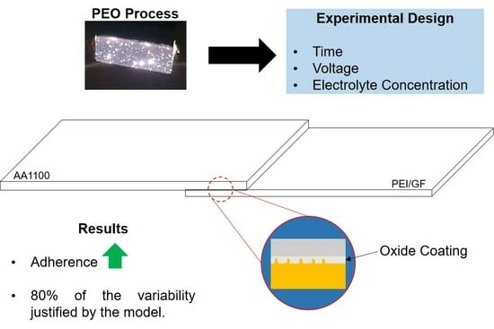
Experimental Design of the Adhesion between a PEI/Glass Fiber Composite and the AA1100 Aluminum Alloy with Oxide Coating Produced via Plasma Electrolytic Oxidation (PEO)

by
Rafael Resende Lucas
*,
Luis Felipe Barbosa Marques
,
Luis Rogerio de Oliveira Hein
,
Edson Cocchieri Botelho
and
Rogério Pinto Mota
*
São Paulo State University (UNESP), School of Engineering and Sciences, Guaratinguetá, São Paulo 12516-410, Brazil
*
Authors to whom correspondence should be addressed.
Ceramics 2024, 7(2), 596-606; https://doi.org/10.3390/ceramics7020039
Submission received: 30 January 2024 / Revised: 13 April 2024 / Accepted: 16 April 2024 / Published: 29 April 2024

Abstract

:
In this study, the AA1100 aluminum alloy underwent the plasma electrolytic oxidation (PEO) process to enhance its adhesion to a thermoplastic composite of polyetherimide (PEI) reinforced with glass fiber, following ASTM D1002:10 standards. A 23 factorial design was employed, varying three parameters in the oxidation process: immersion time, applied electric potential, and electrolyte concentration (Na2B4O7). The joining of aluminum and thermoplastic composite samples was achieved through oxy-fuel welding (OFW), using oxygen and acetylene gases. For the characterization of the joined samples, a universal tensile testing machine was utilized with a displacement speed of 1.5 mm/min. The analysis of the oxide coating involved scanning electron microscopy (SEM), energy-dispersive X-ray spectroscopy (EDS), and Fourier transform infrared spectroscopy (FT-IR). Through variance analysis, it was determined that the statistical model encompasses approximately 80% of the variability in the adhesion process between materials. An improvement of up to 104% in adhesion between the materials was observed with the process, indicating an effective bond due to the presence of the thermoplastic matrix in the treated aluminum sample. This improvement is attributed to the morphology of the oxide coating, resembling corals, with micro-pores and recesses that facilitated mechanical anchoring.
Keywords:
PEO; aluminum; composite

Graphical Abstract

1. Introduction

The use of aluminum alloys and fiber-reinforced engineering polymers, such as glass fiber, carbon fiber, Kevlar@, etc., has been gradually increasing, primarily because these materials ensure that final structures have a lower weight than if they were obtained from other metals [1,2,3]. Applied studies involving hybrid structures are of utmost importance for the aerospace market, which is increasingly adopting the concept of hybrid and electric vehicles. This is exemplified by the Brazilian company Embraer, which has presented conceptual projects with its E19-HE and E30-HE aircraft featuring hybrid electric propulsion. According to the company, this approach will result in a 90% reduction in CO2 production [4,5].
Since the 1930s, aluminum alloys have played a significant role in aeronautical structures. Their use is motivated not only by the ability to reduce the final weight of structures and, consequently, fuel consumption but also by facilitating forming and maintenance processes due mainly to the high malleability of these alloys. However, it is important to note that aluminum alloys are prone to scratching. The depth of these scratches can lead to stress concentration points in the structure [6,7].
To overcome this drawback, surface treatments such as anodization and hard anodization are applied with the aim of forming an aluminum oxide (Al2O3) coating on the alloy. This coating not only imparts notable hardness to the surface but also provides additional benefits, such as improving painting processes by enhancing paint layer adhesion. These techniques play a crucial role in optimizing the properties of aluminum alloys, ensuring the durability and efficiency of aeronautical structures [1,2,3,4,5,6,7,8,9].
Although the anodization process is well established in the market, it is an environmentally degrading process, probably due to the use of acidic solutions (HNO3, HF, etc.), which requires subsequent processes to neutralize by-products. In the case of hard anodization, the environmental impact is exacerbated by the use of hexavalent chromium (Cr6+), making the process not only detrimental to the environment but also harmful to operators [7,8,9,10,11,12].
In order to meet the demands of the United Nations Sustainable Development Goals (SDGs), more environmentally friendly methods have been and are being developed. Among them, one can mention plasma electrolytic oxidation (PEO), among other names. This process is an advanced surface treatment technique for lightweight alloys such as aluminum, titanium, and magnesium. Due to its characteristics, such as the use of high electrical potential (100 to 800 volts), it allows for the treatment of other alloys like tantalum, stainless steel, carbon steel, copper, etc. The PEO process forms an oxide coating on these alloys with strong adhesion and superior physical and chemical properties compared to conventional anodization. Additionally, it is a process that aims to use alkaline electrolytes based on silicates, aluminates, borates, etc. [9,10,11,12,13,14,15,16].
Similar to conventional procedures requiring meticulous parameter control, the PEO process also demands attention to several factors. These include the immersion time of the sample in the liquid medium, the applied electric potential, the applied current density, the temperature of the liquid medium, as well as the chemical composition of both the electrolyte and the sample to be oxidized. Currently, studies involving the process aim to develop optimal parameters for product creation, utilizing statistical models such as Taguchi, linear regression, and analysis of variance (ANOVA), among others [4,7,8,9,10,11,12,13,14,15,16].
In this study, the PEO process was employed in order to induce the controlled growth of a thin layer of aluminum oxide (Al2O3) on the AA1100 aluminum alloy. Three main parameters were varied during this process, including the immersion time of the sample, the applied electric potential, and the electrolyte concentration. Subsequently, the anodized sheet was joined to a sheet of polyetherimide (PEI) thermoplastic composite reinforced with glass fiber through the OFW process. The assessment of the strength of the formed joint was conducted using the single lap shear (LSS) method.
Although there are some studies in the literature on the joining of dissimilar materials, such as aluminum alloys and polymeric composites, the innovation of this work lies in the application of PEO treatment, which makes the process more environmentally efficient. So far, only one study has addressed this approach, conducted by Shore, D. and colleagues (2021) [4], who used the method of bonding with polymeric resin. In this study, oxy-acetylene heating was applied.

2. Materials and Methods

2.1. Thermoplastic Composite Laminates

The laminate used in this work was provided by Toray Advanced Composites. It features a TC1000 matrix, PEI, reinforced with glass fiber (50% in volume), as previously employed in prior studies [7,17]. This material finds extensive applications in the aerospace industry, including seat shells, duct channels, rail interiors, and face sheets for structural sandwich panels. It is characterized by low density (1.27 g/cm3), a relatively high glass transition temperature (217 °C), a degradation temperature of around 460 °C, and a tensile strength of 516 MPa [17,18,19].

2.2. Aluminum Alloy 1100

In this study, we used an aluminum alloy 1100 (commercially pure), with a chemical composition, found in the literature, as follows: from 0.05% to 0.20% Cu; 1.0% Si and Fe; 0.05% Mn (maximum); 0.1% Zn; and 0.15% others, with aluminum balance. All aluminum and composite samples were cut to dimensions of 100 × 25 mm, following ASTM D 1002:10 standards. However, the aluminum samples had a thickness of 3.5 mm, while the composite ones had a thickness of 2.5 mm. After cutting the samples, the aluminum was sanded with silicon carbide sandpaper up to 600 mesh, cleaned in an ultrasonic bath for 900 s, followed by cleaning with isopropyl alcohol (99%), dried with a thermal blower, and stored in boxes with soft paper until the anodization process.

2.3. PEO Surface Treatment Process

In this study, the electrolyte used was sodium tetraborate (Na2B4O7·10H2O). Although electrolytes containing sodium silicate (Na2SiO3) offer better conditions for plasma initiation and maintenance, they tend to break in the oxide coating when subjected to shear forces [4,7]. For the treatment of the samples, an experimental system consisting of a voltage variator (0–400 VDC), a mechanical stirrer with a 304 stainless steel rod, and multimeters to monitor the current and voltage in the system were employed. Additionally, a 430 stainless steel (ferritic) container was used as the cathode. All standards (a total of 17) were conducted with 5 samples each for every new treatment, and the solution was changed to reduce process variability. The treatments occurred in the DC electrical regime, as shown in Figure 1.
After the anodization process, the samples were cleaned with deionized water, dried at room temperature (20 °C), and stored for the welding process.

2.4. Welding Process

The welding process used in this study was oxy-acetylene welding, due to its versatility and low acquisition and maintenance costs, as depicted in Figure 2.
The system used consists of two gas cylinders containing oxygen and acetylene (A), a bench equipped with a movable arm for torch height adjustment (B), and a system for welding dissimilar samples (C). Additionally, clamps were used to ensure intimate contact between the aluminum and the composite. It is important to note that the aluminum sample should be positioned above the composite sample as the heat generated by the flame heats the aluminum, which, through conduction, transfers heat to the composite, softening it.
The gas pressures were set at 0.5 kgf/cm2 for acetylene and 1.0 kgf/cm2 for oxygen. The torch nozzle was positioned at an approximate distance of 70 mm from the aluminum sample. When welding advanced thermoplastic composite materials, it is essential to have an understanding of glass transition temperatures and the degradation temperature [17,18,19]. In this context, the welding temperature should be above the glass transition temperature but below the degradation temperature. To measure the temperature at the junction of the materials, a type K thermocouple connected to a FLUKE TRUE model multimeter was used. With this system, the average temperature reached in the composite was 230 °C. It is worth noting that surface temperature measurement on aluminum leads to inaccurate readings due to rapid heat transfer.

2.5. LSS Test

To perform the lap shear strength (LSS) test on the joined samples, a Shimadzu AG-X universal testing machine was used. The test was conducted with a 50 kN load cell at a speed of 1.5 mm/min, following ASTM D1002:10 standards, as already used in previous studies [4,7,17]. Equation (1) was used to provide the lap shear values (in MPa).
τ = F o r c e m á x A r e a    
where τ : shear strength (MPa); F o r c e m á x : maximum force before joint failure (N); and A r e a : welded area (mm2).

2.6. Characterizations

The pattern that demonstrated superior results was chosen considering a detailed analysis provided by scanning electron microscopy (SEM), which was used to examine the surface morphology in the region responsible for the improvement in adhesion between the materials. For this purpose, a microscope model EVO LS15 from Zeiss was employed, along with energy-dispersive X-ray spectroscopy (EDS) analysis to quantify the constituent elements in the coating. Additionally, the molecular structure of the formed oxides was investigated using an ATR-FTIR spectrometer, Perkin Elmer Spectrum 100 model, covering functional groups in the range of 1000 to 650 cm−1, with 128 scans and a resolution of 4 cm−1.

2.7. Statistical Analysis

In studies of process optimization, independent variables are determined to increase or decrease a response variable. To assess their effects, two levels (minimum and maximum) are employed, resulting in 2k, where k is the number of parameters under investigation. In this study, central composite design (CCD) was utilized with k = 3, representing the immersion time, applied electric potential, and electrolyte concentration (Na2B4O7); the CCD factorial design involves an experimental factorial layout among variables, incorporating central “0” points and axial points (α) to estimate the potential behavior of the response surface. A total of 17 patterns were planned for evaluation, as presented in Table 1 (coded and real variables). For this purpose, Design Expert 6.0 software was used to determine the maximum and minimum values of the parameters.
With the purpose of ensuring the reliability of the statistical analysis, in this study, we employed analysis of variance (ANOVA), which ensures the significance of each parameter, as well as the estimation of the quality of fit. Another aspect evaluated was the correlation coefficient (R2), which quantifies the total variability in the data obtained and how much is explained by the regression model.

3. Results

3.1. Experimental Design (23)

The results derived from the lap shear strength (LSS) test are presented in Table 2, covering a range from 5.4 to 10.7 MPa, with a particular emphasis on experiment 6. The control samples (untreated) showed average values of 5.2 MPa, highlighting the effectiveness of the treatment, resulting in increases ranging from 4 to 104%. Through the construction of the statistical model, the significance of the parameters was assessed using analysis of variance (ANOVA), based on the “desirability” function [20].
Table 2. Values obtained using the LSS test.
StandardCoded VariablesReal VariablesLSS
(MPa)
X1X2X3Time (s)Voltage (V)Concentration (g/L)
00N/AN/AN/AN/AN/AN/A5.2 ± 2.2
01−1−1−13002003.08.0 ± 1.2
02+1−1−19002003.07.3 ± 1.0
03−1+1−13003503.010.5 ± 2.3
04+1+1−19003503.09.2 ± 0.9
05−1−1+130020010.07.9 ± 2.4
06+1−1+190020010.010.7 ± 1.1
07−1+1+130035010.09.3 ± 1.1
08+1+1+190035010.08.8 ± 2.4
09−α00952756.56.6 ± 1.6
100011052756.59.2 ± 1.7
110−α06001506.59.1 ± 1.3
12006004006.57.5 ± 3.9
1300−α6002750.610.0 ± 1.7
140060027512.09.7 ± 1.7
150006002756.58.7 ± 2.1
160006002756.58.2 ± 3.0
170006002756.55.4 ± 1.5
The highest value obtained in this study was 10.7 MPa (marked with a red box) which is close to the values found in the literature, as presented in Table 3 [17,18,19,20].
The statistical model was adjusted by the coefficient of correlation (R2), which represents the percentage of how much the model can explain the variability in the process. In this study, the parameters of plasma electrolytic oxidation include the immersion time, electric potential, and electrolyte concentration (Na2B4O7).
The results of the analysis of variance (ANOVA) for the parameters—time, applied electric potential, and concentration—are presented in Table 4. It is evident that none of the surface treatment parameters show significance concerning the shear strength of the joint, as the values of the “Prob > F” term are higher than 0.05. Additionally, the F-value of 0.55 suggests that the model is not significant due to noise and only accounts for around 80% of the variability, with the ideal being 95% (minimum).
Employing Equation (2), named effect size (η2), which represents the variation between groups as a proportion of the total variation, provides an indication of how much of the lap shear dependent variable’s variation can be attributed to the independent variable [24,25].
η 2 = S S e s p e c i f i c S S T × 100  
where SSespecific: sum of squares of the specific parameter and SST: total sum of squares.
Considering the sum of squares of each parameter under investigation, the following values were obtained: 1.23% for the immersion time, 9.53% for the electrical potential applied to the process, and 0.20% for the concentration of the electrolyte (sodium tetraborate). It was observed that the term “Error Pure”, also known as the “Strange Variable”, contributes approximately 20.5% of all variability of the response variable (Lap Shear).
The high percentage of the uncontrolled variable can be attributed to a number of factors, both in the PEO process and in the OFW welding process. It is notable that among the parameters of the PEO process, there are other factors that can be investigated in future studies, such as electrolyte temperature, the distance between electrodes (GAP), substrate chemical composition, and the use of additives to improve electrolyte conductivity, such as potassium hydroxide (KOH). These factors have a significant impact on the characteristics of oxide coatings; therefore, it is reasonable to assume that they would also have an influence on applied studies [8,9,10,11,12,13,14,15,26,27].
Figure 3 presents a radar chart, illustrating possible parameters to be explored in the PEO process, highlighting the parameters investigated in this study.
If these six parameters were considered in a complete factorial design, 64 factorial points, 12 axial points (considering that this should have a minimum number of twice as many parameters studied), and 10 central points (which guarantee the curvature of the response surface) would be accounted for, totaling 86 experiment patterns. With this, the percentage of the extraneous variable could be reduced (theoretically).

3.2. Morphological and Chemical Analyses of the More Appropriate Test Pattern

The standard that presented the more appropriate welding condition was subjected to scanning electron microscopy (SEM) for morphological analysis of the surface, and together, the chemical composition of the oxide coating generated was evaluated. The morphological evaluation of the generated coating is presented in Figure 4.
By analyzing the surface morphology of the sample submitted to the PEO process, singular microstructures were identified, such as a coral-like configuration, showing pores of irregular geometry originating from high-intensity electrical discharges during the procedure. In addition, micro-cracks were noted, resulting from the rapid cooling of the oxide layer formed. Circular protuberances were also observed, characteristics that have already been documented by other researchers [7,8,9]. The identified pores had a mean diameter of 0.22 ± 0.04 μm.
As previously discussed in the literature, the chemical composition of the coating is a melting of elements coming from both the target alloy and the electrolyte, with the latter playing an active role during the process [7,8,9,10,11,12,13,14]. The EDS analysis, in turn, revealed the following chemical composition of the oxide coating generated: aluminum (Al) representing 58.8%, oxygen (O) comprising 40.0%, chlorine (Cl) representing 0.8%, silicon (Si) providing 0.3%, iron (Fe) contributing 0.2%, and sulfur (S) with a minimum presence of 0.1%, with chlorine and sulfur coming from contaminants in the medium and the manufacturing process, respectively.
In this study, an analysis of molecular composition through the use of FT-IR was conducted in three states: untreated aluminum, aluminum treated with plasma electrolytic oxidation, and after the welding and shearing process, in order to confirm the chemical modifications on the surface. The result of this analysis is shown in Figure 5.
In this evaluation, it was observed that all of the spectra were very different from each other. When focusing on the spectrum corresponding to neat aluminum (black spectrum), very weak bands, around 2286 to 1981 cm−1, were observed, corresponding to functional groups of hydroxyls and CO2 bonds, absorbed from the environment. These same functional groups were detected at 1237 cm−1, due to the chemical composition of the alloy. This behavior was also observed in functional groups Si-O-Si/Si-O-H (1096 and 938 cm−1), in which melting the element Si tends to improve the fluidity of liquid aluminum. The Al-O group was also detected (736 cm−1) due to the passivation process of the alloy, which tends to form a nanometric layer of alumina (Al2O3) on the surface of the alloy [8,9,28,29,30].
In the red spectrum (PEO-treated aluminum), a wide band of around 3600 to 3290 cm−1 was observed, corresponding to hydroxyl elongation vibrations, as presented in 1981 cm−1, indicating the presence of partially hydrated oxide; CO2 and CO 3 2 groups were detected at 2286 and 1420 cm−1, respectively. A significant change occurred in a range below 1000 cm−1, indicating the presence of Al-O, Al-O-Si, and Al-O-H bonds, with a notable increase in these bonds after plasma anodization treatment [8,9,28].
In the aluminum spectrum after welding (green), the presence of functional groups such as CO2 and possible hydroxyl groups was observed from 2286 to 1981 cm−1; at 1719 cm−1; and at 1224 cm−1. There are also vibrations of bending and stretching of C-N, the aromatic ether of C–O–C, and asymmetric and symmetric stretching vibrations of carbonyl imide (1780 and 737 cm−1). The presence of CO 3 2 groups around 1475 cm−1 was noted, as well as vibrations of stretching and/or asymmetric balance of C-O and/or C-H. Groups below 1000 cm−1 are complex to analyze due to the possible formation of compound groups, such as polymer and oxide (polymer + oxide + fiber) [8,9,18,28,31,32].

4. Conclusions

In this study, the PEO process was employed to improve adhesion between the AA1100 aluminum alloy and a PEI thermoplastic composite reinforced with glass fiber; thus, it can be concluded that:
  • Adhesion between polyetherimide reinforced with glass fiber and 1100 aluminum was significantly improved. Single lap shear tests indeed showed a doubling of shear strength: ~5 to 10 ± 1 MPa. This value is higher than that shown for some methods of joining dissimilar materials.
  • Through the analysis of variance, it was found that the statistical model addressed in this study covers approximately 79.5% of all variability in the process of joining materials. This value is attributed to the high percentage of the “error pure” variable, which in this case was 20.5%.
  • When evaluating the surface morphology of the plasma-anodized alloy, a coral-like microstructure was observed with pores distributed across the entire surface. However, there was no control over the density of these pores, with a diameter of 0.22 µm, as well as micro-cracks due to the rapid cooling of the liquid oxide coating. Additionally, spherical protrusions were present, and these characteristics have been previously mentioned in the literature.
  • The chemical composition on the surface of the oxide coating was essentially composed of elements from the treated alloy. The presence of elements from the electrolyte used is not very evident.
  • In line with the analysis of the composition of identified elements, FT-IR investigation revealed the presence of Al-O/Al-O-Si functional groups. After the welding process and with visual evidence of polymer on the surface of the treated aluminum, there were flexural and stretching vibrations of C-N, as well as other functional groups below 1000 cm−1, indicating the possible formation of compounds, such as polymer + oxide.

Author Contributions

Conceptualization, R.R.L.; methodology, R.R.L. and L.F.B.M.; validation, R.P.M. and E.C.B.; formal analysis, R.R.L., L.F.B.M. and L.R.d.O.H.; investigation, R.R.L.; resources, R.P.M. and E.C.B.; data curation, R.R.L.; writing—original draft preparation, R.R.L.; writing—review and editing, R.R.L.; visualization, R.P.M.; supervision, R.P.M.; project administration, R.P.M.; funding acquisition, R.P.M. and E.C.B. All authors have read and agreed to the published version of the manuscript.

Funding

This research was funded by the Coordination for the Improvement of Higher Education Personnel (CAPES), grant number 88887.827403/2023-00, and the APC was funded by PROPG, grant number 16/2024.

Institutional Review Board Statement

Not applicable.

Data Availability Statement

The original contributions presented in the study are included in the article, further inquiries can be directed to the corresponding author.

Acknowledgments

The authors thank LapTec—Unesp Sorocaba for the microscopy analyses.

Conflicts of Interest

The authors declare no conflicts of interest.

References

  1. Megahed, M.; El-Baky, M.A.A.; Alsaeedy, A.M.; Alshorbagy, A.E. Improvement of Impact and Water Barrier Properties of GLARE by Incorporation of Different Types of Nanoparticles. Fibers Polym. 2020, 21, 840–848. [Google Scholar] [CrossRef]
  2. Almeida, R.S.; Damato, C.A.; Botelho, E.C.; Pardini, L.C.; Rezende, M.C. Effect of surface treatment on fatigue behavior of metal/carbon fiber laminates. J. Mater. Sci. 2008, 43, 3173–3179. [Google Scholar] [CrossRef]
  3. Thomas, L.C.; Kumar, V.; Gangwar, A.; Pisupati, M.; Gupta, C.; Panda, S.K. Computational Modelling and Experimental Techniques for Fibre Metal Laminate Structural Analysis: A Comprehensive Review. Arch Comput. Methods Eng. 2024, 31, 351–369. [Google Scholar] [CrossRef]
  4. Shore, D.; Wilson, J.C.A.-B.; Matthews, A.; Yerokhin, A. Adhesive bond strength of PEO coated AA6060-T6. Surf. Coat. Technol. 2021, 428, 127898. [Google Scholar] [CrossRef]
  5. Embraer: News-Embraer–“The Shape of Things to Come, New Sustainable Aircraft Concepts Revealed”. 2022. Available online: https://newsroom.aviator.aero/embraer-the-shape-of-things-to-come-new-sustainable-aircraft-concepts-revealed/ (accessed on 2 December 2023).
  6. Khalid, M.Y.; Umer, R.; Khan, K.A. Review of recent trends and developments in aluminium 7075 alloy and its metal matrix composites (MMCs) for aircraft applications. Results Eng. 2023, 20, 101372. [Google Scholar] [CrossRef]
  7. Lucas, R.R. Estudo da Oxidação Eletrolítica a Plasma na liga AA2024-T3 para Soldagem com Compósito PEI/Fibra de vidro. Available online: http://hdl.handle.net/11449/234558 (accessed on 15 June 2023).
  8. Jadhav, P.; Bongale, A.; Kumar, S. A review of process characteristics of plasma electrolytic oxidation of aluminium alloy. J. Phys. Conf. Ser. 2021, 1, 1854. [Google Scholar] [CrossRef]
  9. Lucas, R.R.; Mota, R.P.; Abrahão, A.B.R.M.; Botelho, E.C.; Sales-Contini, R.C.M. Characterization of oxide coating grown by plasma electrolytic oxidation (PEO) at different times on aluminum alloy AA2024-T3. MRS Commun. 2022, 12, 266–271. [Google Scholar] [CrossRef]
  10. Karbasi, M.; Nikoomanzari, E.; Hosseini, R.; Bahramian, H.; Chaharmahali, R.; Giannakis, S.; Kaseem, M.; Fattah-Alhosseini, A. A review on plasma electrolytic oxidation coatings for organic pollutant degradation: How to prepare them and what to expect of them? J. Environ. Chem. Eng. 2023, 11, 110027. [Google Scholar] [CrossRef]
  11. Christudasjustus, J.; Vukkum, V.; Gupta, R. Evolution of surface film in AA2024-T3 after a long-term immersion in NaCl solution. Corros. Sci. 2023, 215, 111056. [Google Scholar] [CrossRef]
  12. Kaseem, M.; Dikici, B. Optimization of Surface Properties of Plasma Electrolytic Oxidation Coating by Organic Additives: A Review. Coatings 2023, 11, 374. [Google Scholar] [CrossRef]
  13. Chaharmahali, R.; Fattah-Alhosseini, A.; Karbasi, M.; Giannakis, S.; Bahramian, H.; Oulego, P. A systematic study on modulation of plasma electrolytic oxidation parameters for optimizing photocatalytic coatings on titanium substrates. J. Alloys Compd. 2023, 963, 171234. [Google Scholar] [CrossRef]
  14. Shahri, Z.; Allahkaram, S.; Soltani, R.; Jafari, H. Optimization of plasma electrolyte oxidation process parameters for corrosion resistance of Mg alloy. J. Magnes. Alloys 2020, 8, 431–440. [Google Scholar] [CrossRef]
  15. “Taguchi Optimization of Electrolytic Plasma Hardening Process Parameters on Ti-6Al-4V Alloy: Microstructure and Mechanical Properties-Ayday-2023-Advanced Engineering Materials-Wiley Online Library”. Available online: https://onlinelibrary.wiley.com/doi/10.1002/adem.202300896 (accessed on 15 January 2024).
  16. Vargas, C.A.; Zuleta, A.A.; Botero, C.A.; Baena, L.M.; Castaño, J.G.; Gómez, M.A.; Tamayo, J.A. Morphological analysis of plasma electrolytic oxidation coatings formed on Ti6Al4V alloys manufactured by electron beam powder bed fusion. Heliyon 2023, 9, e19289. [Google Scholar] [CrossRef]
  17. Oliveira, V.S.; Society, A.W.; Lucas, R.R.; Carvalho, T.P.; Marques, L.F.; Reis, J.F.; Abrahão, A.B.R.M.; Botelho, E.C. Development of the Oxyacetylene Welding Process for PEI/Glass Fiber Laminates. Weld. J. 2021, 100, 142–149. [Google Scholar] [CrossRef]
  18. Rajak, D.K.; Wagh, P.H.; Linul, E. Manufacturing Technologies of Carbon/Glass Fiber-Reinforced Polymer Composites and Their Properties: A Review. Polymers 2021, 13, 3721. [Google Scholar] [CrossRef] [PubMed]
  19. Wang, J.; Lu, C.; Xiao, C.; Cheng, J.; Ren, R.; Xiong, X. Heat distribution simulation and effects of ultrasonic welding amplitude on carbon fiber/polyetherimide composite joint properties. Mat. Lett. 2023, 340, 134148. [Google Scholar] [CrossRef]
  20. Salazar, J.M.G.; Soria, A.; Barrena, M.I. Welding of AA6061-(Al2O3)p composite: Effect of weld process variables and post-welding heat treatment on microstructure and mechanical properties. Sci. Tech. Weld. Join. 2013, 10, 339–343. [Google Scholar] [CrossRef]
  21. Abibe, A.; Sônego, M.; dos Santos, J.; Canto, L.; Amancio-Filho, S. On the feasibility of a friction-based staking joining method for polymer–metal hybrid structures. Mater. Des. 2016, 92, 632–642. [Google Scholar] [CrossRef]
  22. Aliasghari, S.; Ghorbani, M.; Skeldon, P.; Karami, H.; Movahedi, M. Effect of plasma electrolytic oxidation on joining of AA 5052 aluminium alloy to polypropylene using friction stir spot welding. Surf. Coat. Technol. 2017, 313, 274–281. [Google Scholar] [CrossRef]
  23. Schäfer, H.; Blaga, L.; Stöver, E.; Klusemann, B. Refill friction stir spot welding of thermoplastic composites: Case study on Carbon-fiber-reinforced polyphenylene sulfide. Thin-Walled Struct. 2023, 191, 111037. [Google Scholar] [CrossRef]
  24. Richardson, J.T.E. Eta squared and partial eta squared as measures of effect size in educational research. Educ. Res. Rev. 2011, 6, 135–147. [Google Scholar] [CrossRef]
  25. Kroes, A.D.A.; Finley, J.R. Demystifying omega squared: Practical guidance for effect size in common analysis of variance designs. Psychol. Methods 2023. [Google Scholar] [CrossRef] [PubMed]
  26. Zehra, T.; Patil, S.A.; Shrestha, N.K.; Fattah-Alhosseini, A.; Kaseem, M. Anionic assisted incorporation of WO3 nanoparticles for enhanced electrochemical properties of AZ31 Mg alloy coated via plasma electrolytic oxidation. J. Alloys Compd. 2022, 916, 165445. [Google Scholar] [CrossRef]
  27. Wu, J.; Wu, L.; Yao, W.; Chen, Y.; Chen, Y.; Yuan, Y.; Wang, J.; Atrens, A.; Pan, F. Effect of electrolyte systems on plasma electrolytic oxidation coatings characteristics on LPSO Mg-Gd-Y-Zn alloy. Surf. Coat. Technol. 2023, 454, 129192. [Google Scholar] [CrossRef]
  28. Santos, J.S.; Márquez, V.; Buijnsters, J.G.; Praserthdam, S.; Praserthdam, P. Antimicrobial properties dependence on the composition and architecture of copper-alumina coatings prepared by plasma electrolytic oxidation (PEO). Appl. Surf. Sci. 2023, 607, 155072. [Google Scholar] [CrossRef]
  29. Dalmoro, V.; dos Santos, J.H.; Armelin, E.; Alemán, C.; Azambuja, D.S. A synergistic combination of tetraethylorthosilicate and multiphosphonic acid offers excellent corrosion protection to AA1100 aluminum alloy. Appl. Surf. Sci. 2013, 273, 758–768. [Google Scholar] [CrossRef]
  30. Otani, Y.; Sasaki, S. Effects of the addition of silicon to 7075 aluminum alloy on microstructure, mechanical properties, and selective laser melting processability. Mater. Sci. Eng. A 2020, 777, 139079. [Google Scholar] [CrossRef]
  31. Nabavi, H.F.; Aliofkhazraei, M. Morphology, composition and electrochemical properties of bioactive-TiO2/HA on CP-Ti and Ti6Al4V substrates fabricated by alkali treatment of hybrid plasma electrolytic oxidation process (estimation of porosity from EIS results). Surf. Coat. Technol. 2019, 375, 266–291. [Google Scholar] [CrossRef]
  32. Pritam; Arya, A.; Sharma, A.L. Selection of best composition of Na+ ion conducting PEO-PEI blend solid polymer electrolyte based on structural, electrical, and dielectric spectroscopic analysis. Ionics 2019, 26, 745–766. [Google Scholar] [CrossRef]
Figure 1. Graph of voltage and current in the system over time.
Ceramics 07 00039 g001
Figure 2. Welding equipment, A—gas cylinders oxygen and acetylene, B—movable arm and torch, C—Aluminum and thermoplastic composite being welded.
Ceramics 07 00039 g002
Figure 3. Radar chart with some PEO process parameters that affect oxide coating characteristics.
Ceramics 07 00039 g003
Figure 4. Scanning electron microscopy image of the AA1100 aluminum alloy treated using the PEO process, from process 6.
Ceramics 07 00039 g004
Figure 5. ATR FT-IR spectra of aluminum sample in the 3 states.
Ceramics 07 00039 g005
Table 1. Coded values of the applied variables.
VariableCodedLevels
−α−10+1
Time (s)X1953006009001105
Voltage (V)X2150200275350400
Concentration (g/L)X30.63.06.510.012.0
Table 3. Results identified in the literature regarding the joining of dissimilar materials.
Method and Materials UsedResistance (MPa)Ref.
This study10.7-
Welding with oxy-gas LPG/PEI glass fiber + AA2024 (PEO)8.5[7]
Welding with oxy-gas/PEI glass fiber + PEI glass fiber12.5[17]
Friction Injection Joining (F-IJ)/AA6082-T6 + PEI glass fiber1.1[21]
Friction Stir Spot Welding (FSSW)/AA5052 (PEO) + Polypropylene1.36[22]
Friction Stir Spot Welding (FSSW)/CF-PPS + CF-PPS2.4[23]
Table 4. Analysis of variance (ANOVA) for the cubic model of the hybrid system.
SourceSum of SquaresMean SquareF ValueProb > F
Model24.521.750.550.7994
Time0.380.380.120.7632
Voltage2.942.940.930.4368
Concentration0.0610.0610.0190.9021
Time20.260.260.0830.8008
Voltage20.900.900.280.6469
Concentration23.963.961.250.3794
Time—Voltage1.901.900.600.5193
Time—Concentration2.312.310.730.4827
Voltage—Concentration3.003.000.950.4328
Time31.791.790.570.5303
Voltage33.073.070.970.4285
Concentration30.0620.0620.0200.9015
Time2.Concentration0.0740.0740.0230.8925
Time.Voltage.Concentration0.910.910.290.8925
Error Pure6.333.16--
R279.94%
Disclaimer/Publisher’s Note: The statements, opinions and data contained in all publications are solely those of the individual author(s) and contributor(s) and not of MDPI and/or the editor(s). MDPI and/or the editor(s) disclaim responsibility for any injury to people or property resulting from any ideas, methods, instructions or products referred to in the content.

