Article

Design and Parameter Optimization of a Dual-Disc Trenching Device for Ecological Tea Plantations

1
College of Mechanical and Electrical Engineering, Fujian Agriculture and Forestry University, Fuzhou 350002, China
2
Fujian University Engineering Research Center for Modern Agricultural Equipment, Fujian Agriculture and Forestry University, Fuzhou 350002, China
*
Author to whom correspondence should be addressed.
Agriculture 2024, 14(5), 704; https://doi.org/10.3390/agriculture14050704
Submission received: 20 March 2024 / Revised: 26 April 2024 / Accepted: 26 April 2024 / Published: 29 April 2024
(This article belongs to the Section Agricultural Technology)

Abstract

:
This paper addresses challenges in the application of existing colters in Chinese ecological tea plantations due to abundant straw roots and insufficient tillage depth. Aligned with the agronomic requirements of hilly eco-tea plantations, our study optimizes the structural advantages of the joint use of rotary tillage blades and double-disc colters to design an efficient trenching device. Our investigation explores the motion characteristics of a double-disc colter during deep trenching operations, in conjunction with rotary tillage blades. Employing discrete element method (DEM) simulations, this paper aims to minimize the working resistance and enhance the tillage depth stability. Single-factor experiments are conducted to determine the impact of key structural parameters on the tillage depth stability and working resistance. The optimal parameters are determined as a relative height of 80 mm to 120 mm, a 280 mm to 320 mm diameter for the double-disc colter, and a 10° to 14° angle between the two discs. The central composite design method is used to optimize the structural parameters of the double-disc colter. The results indicate that when the relative height is 82 mm, the diameter of the double-disc colter is 297 mm, and the angle between the two discs is 14°, the tillage depth stability performance reaches 91.64%. With a working resistance of merely 93.93 N, the trenching device achieves optimal operational performance under these conditions. Field validation testing shows a tillage depth stability coefficient of 92.37% and a working resistance of 104.2 N. These values deviate by 0.73% and 10.93%, respectively, from the simulation results, confirming the reliability of the simulation model. A field validation test further confirms that the operational performance of the colter aligns with the agronomic requirements of ecological tea plantations, offering valuable insights for research on trenching devices in such environments.

Graphical Abstract

1. Introduction

Tea, with its origins in China, holds a prominent place among the world’s top three beverages [1]. As the leading producer and consumer of tea, China has seen a growing inclination towards intercropping green manure in eco-tea plantations. This shift is fueled by the increasing popularity of green and sustainable development concepts, alongside a heightened demand for tea quality. Integral to cultivation practices in eco-tea plantations are trenching, fertilization, and soil coverage. Given that eco-tea plantations are primarily located in hilly regions with narrow ridge spacing and dense soil root systems, the design of colters is critically important. Consequently, numerous scholars have conducted extensive research on colter design.
In the realm of rotary tillage colter research, several scholars employ the discrete element method to analyze the operational processes of rotary tillage blades [2,3,4]. To capture dynamic variations in and motion patterns during their operation, researchers employ high-speed camera technology to observe and analyze the motion trajectory of rotary tillage colters [5,6]. Additionally, Ahmadi et al. [7] developed a comprehensive kinematic and dynamic model for rotary tillage blades using classical mechanics principles, effectively predicting the torque and power required for rotary tillage operations. Ma C et al. [8] have established an optimization model for trenching performance quality, successfully identifying the optimal parameter combination for influencing trenching factors. Zhang et al. [9], utilizing response surface methodology, optimize the key structural parameters of rotary tillage colters. However, despite these efforts, rotary tillage colters continue to face challenges such as a high level of resistance and suboptimal performance during practical operations. In response, certain scholars have delved into advanced techniques, such as reverse engineering technology and biomimicry, to enhance the design of rotary tillage colters [10,11]. Additionally, optimizing double-disc colters as field trenching tools has been a central focus of research, with scholars conducting thorough investigations into reducing the working resistance of these tools and optimizing key structural parameters [12,13,14,15,16,17]. However, double-disc colters are susceptible to blockages during field operations. Hu H et al. [18] proposed a cooperative operation method using ultra-high-pressure water jets with double-disc colters, enhancing their straw-cutting efficiency while avoiding blockage issues. To improve the straw cutting efficiency of double-disc colters, scholars have made significant progress by modifying their structure [19,20,21]. The stability of tillage depth is a crucial indicator for assessing trenching effectiveness. Ye R et al. [22] improved tillage depth stability through the discrete element method optimization of the corrugated double-disc colters’ structural parameters. Sugirbay A et al. [23] designed a straight-diagonal double-disc colter, enhancing tillage depth stability through an improved design. Additionally, scholars have compared the performance of double-disc colters with that of other types. Francetto T R et al. [24] compared the soil disturbance, trench depth, and width variations at different forward speeds of a hoe-type colter and a double-disc colter. Karayel D.’s [25] research further confirmed the advantages of double-disc colters in terms of their uniform trenching depth, demonstrating more stability compared to hoe-type colters. Wang W et al. [26] designed a double-disc colter with a compaction device, effectively reducing issues such as soil protrusion and soil recompaction during the operation process. Employing the analytic hierarchy process (AHP) enables an objective evaluation of the performance of the mechanism, also serving as one of the crucial research directions for designing the structure of trenching devices [27].
Currently, international research and applications regarding colters primarily focus on flat farmland or orchard backgrounds. In such environments, there is ample space available for machinery operations and sufficient matching power allow for simultaneous multi-row operations. However, in hilly areas with eco-tea plantations, the narrow row spacing, high requirements for the overall dimensions of the machinery, and difficulties in equipping power units have led to a relative scarcity of trenchers suitable for such operations. Therefore, this paper proposes a trenching scheme specifically tailored for eco-tea plantations. This approach involves the initial trenching using a rotary tiller, followed by a secondary trenching operation with a double-disc colter. This methodology aims to enhance the stability of tillage depth and effectively sever residual root systems. Through a theoretical analysis, the key structural parameters that influence the trenching device’s performance are identified, and a DEM simulation is established. With the objectives of improving tillage depth stability and reducing working resistance, single-factor and central composite experiments are designed. The optimal parameter combination is determined through a response surface analysis, and the effectiveness of the optimized structural parameters is validated through field experiments.

2. Materials and Methods

2.1. Structure and Operational Principles of the Colter

The colter is mounted on the eco-tea plantation trenching and fertilizing integrated machine. This machine comprises the following essential components: engine, transmission system, control mechanism, fertilizing device, trenching device, depth-limiting wheel, and driving wheel. With overall dimensions of 1800 mm × 600 mm × 900 mm (length × width × height) and equipped with a 177F model engine, the complete machine structure is depicted in Figure 1a.
Trenching operations involve two key phases: initial clearing with the rotary tillage blade and subsequent trenching and shaping with the double-disc colter. In Figure 1b, the rotary tillage blade comprises components like the blade holder, trenching blade, and fixed nut, which are installed on the equipment’s gearbox output shaft. The trenching blade is a trenching and soil-throwing blade developed earlier by the research team for eco-tea plantations, features a rotating radius of 245 mm, a 230 mm endpoint radius of the side-cutting edge, a 110° tangential deflection angle, a soil-throwing area of 3500 mm², and a 130° angle between soil-throwing plate and lateral cutting face. Figure 1c shows the double-disc colter mounted on the equipment’s end beam, consisting of components like disc blades, frame assembly, fertilizer discharge tube, compression spring, and soil scraper. Following the rotary tillage blade’s preliminary trenching, the double-disc colter deepens the trench along the groove. Figure 2 illustrates the operational process of the eco-tea plantation trenching device.

2.2. Motion Characteristics and Force Analysis

During forward motion, the machine encounters soil resistance from cutting at the circular blade edges and compression forces on the disc surfaces. We used the Cartesian coordinate system in Figure 3, where the x-axis aligns with the forward direction, the y-axis represents horizontal direction, and the z-axis signifies vertical direction. Let V m be the machine’s forward velocity and point E denote a specific mass point on the two discs. The angle between two discs is ϕ, and the angle at position m on the convergence point of the two discs is β.
In this coordinate system, the normal vectors of the double-disc plane are as follows:
n 1 = sin ϕ 2 · cos β , cos ϕ 2 , sin ϕ 2 · sin β
n 2 = sin ϕ 2 · cos β , cos ϕ 2 , sin ϕ 2 · sin β
The resistance Q of cutting soil at the disc blade is given as follows:
Q = L q dl
L = R θ = Rarccos R h 2 R
Solving for Q:
Q = qRarccos R h 2 R h 2 R 2 R h 2 h 2 2
where Q represents the cutting force; L is the arc length of contact between the disc blade edge and the soil; q is the force exerted by the soil on the disc blade edge; R is the radius of the double discs; and h 2 is the trenching depth of the double-disc colter.
During the forward motion, overcoming soil compression force necessitates a reaction force F N which is exerted on the plane of the double discs. Therefore, the reaction force formed on the plane of the double discs is denoted as F:
F = F N · sin ϕ 2 · cos β · A + F N · f · cos ϕ 2 + Q
In the equation, F N represents the force exerted by the double discs on the soil; A denotes the contact area between the double discs and the soil; and f is the friction coefficient between the soil and the double discs.
The contact area A between the plane of the double discs and the soil can be determined by subtracting the area of the triangle from the area of the sector.
A = R 2 · arccos R h 2 R R h 2 2 R h 2 h 2 2
where A denotes the contact area between the double discs and the soil; R is the radius of the double discs; and h 2 is the trenching depth of the double-disc colter.
Assuming no soil recompaction after the operation of the rotary tillage blade and double-disc colter, the trenching depth h 2 of double-disc colter is determined as follows:
h 2 = R h 0 + h 1 L 2
where h 0 is the vertical distance from the mass point of the rotary tillage blade to the ground; h 1 is the depth of the trenching and soil-throwing blade; and L2 denotes the vertical distance between rotary tillage blade and the double-disc colter mass point.
Based on the practical demands of the assignment, it is stipulated that h1 should be greater than or equal to 0, and h2 should also be greater than or equal to 0. In the joint operation of the entire machine, the total trenching depth (H) of the trenching device is as follows:
H = R h 0 + L 2
Tillage depth stability coefficient U j is as follows:
H - = i = 1 n H i n S j = i = 1 n H i H - 2 n 1 V j = S j H - × 100 % U j = 1 V j
In the equation, H ¯ represents the average tillage depth for the j th pass; H i is the tillage depth at the i th point within the j th pass; n signifies the fixed number of measurement points in the j th pass; S j denotes the standard deviation of tillage depth for the j th pass; V j is the coefficient of variation for tillage depth in the j th pass; and U j is the tillage depth stability coefficient for the j th pass.
Through both theoretical analysis and practical operational experience, factors influencing the effectiveness of the double-disc colter primarily encompass the vertical distance (L2) between rotary tillage blade and the double-disc colter’s mass point, the radius (R) of the double-disc colter, the angle (ϕ) between the two discs, the angle (β) of convergence point of two discs, and the vertical distance (h0) from the mass point of rotary tillage blade to the ground. With careful consideration of the agronomic requirements of ecological tea plantations, the vertical distance (h0) between the rotary tillage blade’s mass point and the ground is set to 150 mm. Additionally, the angle (β) of convergence point of two discs is determined to be 70° to prevent blockages in the double-disc colter.

2.3. Discrete Element Method Simulation Experiments

2.3.1. Discrete Element Simulation Modeling

This study employed EDEM 2022 software to construct DEM simulation models, mimicking actual operational scenarios in ecological tea plantations. To enhance simulation efficiency, simplifications were applied to the colter model. Using SolidWorks 2021 software, models of rotary tillage blade, soil deflector plate, double-disc colter, and soil troughs were drafted and saved in IGS format before being imported into the EDEM software for investigating the dynamic interactions between colter and soil. Considering ecological tea garden agronomic requirements and practical production experience, the colter’s forward speed was set to 0.5 m/s, the rotary tillage blade’s rotational speed was set to 300 r/min, and the distance between the blade’s mass point and the ground was set to 150 mm (Figure 4).
(1)
Trenching Device Model
In the DEM simulation process, the precision of geometric model parameters can significantly impact experimental outcomes. Therefore, based on real production processes, the colter’s material properties were set to 1566 steel. Contact relationships were established using EDEM software’s preprocessing module (Table 1). This study adopted the Hertz–Mindlin (no slip) contact model to simulate the interaction between colter and soil.
(2)
Soil Discrete Element Model
To better approximate real field conditions, parameters of ecological tea garden soil and straw were selected to establish the discrete element model. The dimensions of the soil trough were 1200 mm in length, 500 mm in width, and 400 mm in height, generating a total of 300,000 soil particles. The soil particles had a diameter of 4 mm and a bonding radius of 4.35 mm. Upon reaching stable soil generation, 200 straw particles were randomly distributed on the soil surface, each with a length of 50 mm. Other simulation parameters are listed in Table 2.

2.3.2. Single-Factor Experiments

Based on motion analysis during the operation process of the double-disc colter, the following key factors affecting trenching performance were identified through theoretical analysis: the vertical distance (referred to as “relative height”) between the rotary tillage blade and double-disc colter mass point, the diameter of double-disc colter (referred to as “double-disc diameter”), and the angle between two discs (referred to as “angle between two discs”). These factors were chosen as our experimental variables, with tillage depth stability coefficient and working resistance chosen as our evaluation criteria. Single-factor dynamic simulations of the trenching process were performed using EDEM discrete element simulation software, with the experiments being repeated five times each and their averages calculated. The influence of different installation positions and double-disc structural parameters on tillage depth stability and working resistance was analyzed. Experimental factor levels are summarized in Table 3.

2.3.3. Multi-Factor Experiments

In order to further optimize the structural parameters of double-disc colter for joint operations, building upon the foundation of single-factor experiments, comprehensive consideration was given to factors such as ecological tea garden agronomy, operational environment, and trenching performance indicators. After analysis, ideal ranges for each factor were determined. To achieve the best performance, a three-factor, five-level central composite design experiment was conducted to identify the optimal parameter combination. A factor level coding table (Table 4) was established, with tillage depth stability and working resistance as evaluation criteria. Each experiment was repeated five times, and the averages were calculated to obtain the final experimental results.

2.4. Field Verification

To confirm the simulation model’s reliability, the double-disc colter with optimized structural parameters was fabricated. Due to the inconvenience of directly measuring the double-disc colter’s working resistance on machinery, an adjustable test stand cart was assembled along with a tension testing instrument (HP-1K) (Yueqing Aibao Instrument Co., Ltd., Yueqing City, Wenzhou City, China) for evaluation. Field experiments were conducted in the ecological tea garden area of Wuyishan City, Nanping, Fujian Province, with a moisture content of 18.6%. Key equipment included the test stand cart, double-disc colter, tension testing instrument, rotary tillage blade, counterweights, and steel ruler. To simplify testing, the rotary tillage blade was mounted on the machinery prior to the experiment and the distance between the blade’s mass point and the ground was set to 150 mm, with a forward speed of 0.5 m/s and a rotation speed of 300 rad/min. Subsequently, the initial trenching operation was initiated. The double-disc colter, set to a relative height of 80 mm to rotary tillage blade, was installed on the test stand cart. Throughout the experiment, the test stand cart advanced at 0.5 m/s, and double-disc colter performed secondary trenching along the furrow, as depicted in Figure 5. Five replicate experiments were conducted. The trenching depth was measured with a steel ruler, and the working resistance was measured using the tension testing instrument. The average values were then calculated to determine the final tillage depth stability coefficient and working resistance.

3. Results and Discussion

3.1. Simulation Analysis

During the DEM simulation, soil particles were generated and allowed to settle naturally from 0 to 6 s, while straw particles were randomly distributed on the soil surface. At 6.2 s, the rotary tillage blade entered the soil trough, rotating around its own center and moving in the X-axis direction. As it rotated, it ejected the soil and straw particles outward, forming initial furrows. The double-disc colter began to deepen the furrow trajectory that was created by the rotary tillage blade at 6.5 s. At 7.3 s, both the rotary tillage blade and double-disc colter exited the soil trough, marking the end of the simulation. For post-processing, we exported the working resistance data of the double-disc colter and the cross-sectional profile of the furrow.
As shown by the post-processing interface of the EDEM software and Figure 6a, after the trenching operation, most of the surface straw within the working area was effectively cleared, while some soil accumulated on the soil-throwing side, causing soil recompaction. Following the operation of the double-disc colter, Figure 6b indicates that the furrows became more even. Within the furrow after the operation, trench depth measurements were taken at intervals of 200 mm along a sampled plane, as depicted in Figure 6b. The average of these measurements was calculated to determine the final trench depth, from which the tillage depth stability coefficient was derived.

3.2. Analysis of Single-Factor Experimental Results

(1)
The Influence of Relative Height on Performance Indicators
Under the condition in which the distance between the rotary tillage blade’s mass point and the ground is 150 mm, the double-disc’s diameter is 300 mm, and the angle between the two discs is 14°, single-factor experiments were conducted with the following relative heights: 60 mm, 80 mm, 100 mm, 120 mm, and 140 mm. Each experiment was repeated five times, and the average results were analyzed to assess the impact of the relative height on the tillage depth stability and the working resistance of the double-disc colter (refer to Figure 7).
The tillage depth stability increases between relative heights of 60 mm and 100 mm but gradually decreases from 100 mm to 140 mm, reaching its peak at 100 mm. Simultaneously, there is an overall increase in the working resistance of the double-disc colter. This is attributed to reduced contact between the double-disc colter and the soil at lower relative heights, resulting in a decreased level of trenching resistance. Based on the single-factor results and considering the agronomic requirements of the ecological tea garden, the optimal relative height range is determined to be 80–120 mm.
(2)
The Influence of Double-Disc Diameter on Performance Indicators
Under the condition in which the distance between the rotary tillage blade’s mass point and the ground is 150 mm, the angle between the two discs is 14°, and the relative height is 100 mm, single-factor experiments were conducted with the double-disc diameters set to 260 mm, 280 mm, 300 mm, 320 mm, and 340 mm. Each experiment was repeated five times under constant parameters, and the average results were obtained. The trends of different double-disc diameters on the tillage depth stability and the working resistance of the double-disc colter were analyzed (refer to Figure 8).
The tillage depth stability increased from double-disc diameters of 260 mm to 300 mm but decreased from 300 mm to 340 mm, peaking at a diameter of 300 mm. Larger double-disc diameters corresponded to higher levels of the overall working resistance of the colter, with the lowest resistance recorded at a diameter of 260 mm. As the diameter increased, the discs made greater contact with the soil, resulting in increased soil disturbance and decreased tillage depth stability, alongside heightened levels of working resistance. Considering the single-factor results and the agronomic requirements of the ecological tea garden, a double-disc diameter range of 280 mm to 320 mm is optimal.
(3)
The Influence of Angle between Two Discs on Performance Indicators
Under the condition in which the distance between rotary tillage blade’s mass point and the ground is 150 mm, the relative height is 100 mm, and the double-disc diameter is 300 mm, single-factor experiments were conducted with the following angles between the two discs: 10°, 12°, 14°, 16°, and 18°. Each experiment was repeated five times, and the average values of performance indicators were analyzed to examine the impact of different angles between the two discs on the tillage depth stability and the working resistance of the colter (refer to Figure 9).
Within the range of 10° to 14°, tillage depth stability gradually increased, while the working resistance of the colter rose slowly. Conversely, angles between 14° and 18° resulted in a decrease in the tillage depth stability and a rapid increase in the levels of working resistance. This is attributed to the larger contact area of the colter with the soil as the angle increases, leading to soil recompaction and compression at the bottom of the furrow, forming a “W” shape. As a result, actual trench depth measurements become shallower, and the level of working resistance increases. The optimal angle for achieving the maximum tillage depth stability was found to be 14°, while the angle yielding the minimum working resistance was 10°. Considering the single-factor results and the agronomic requirements of the ecological tea garden, an ideal angle range of 10° to 14° is recommended.

3.3. Analysis of Multi-Factor Experiment Results

This study utilized a three-factor, five-level central composite design experiment to explore the optimal operational parameters of the trenching device. Regression models were established to correlate each factor with experimental performance indicators, providing a comprehensive evaluation of the tillage depth stability and working resistance. Throughout the experimental process, the central composite experimental design scheme aligned with the table of experimental factor levels. The colter’s forward speed was set to 0.5 m/s, the rotary tillage blade’s rotational speed was set to 300 r/min, and the distance between the blade’s mass point and the ground was set to 150 mm. With all the other parameters held constant, each experiment was repeated five times, and the average values were analyzed as the experimental results, as shown in Table 5.
(1)
The Impact of Experimental Factors on Tillage Depth Stability Coefficient
Based on the data in Table 6, the tillage depth stability coefficient model for the double-disc colter demonstrates a significant effect (p < 0.01), with a non-significant lack-of-fit term (p > 0.05), indicating the significance of the model and the insignificance of the lack-of-fit term. Thus, the model is meaningful. The p-value associated with the angle between two discs is less than 0.01, signifying a highly significant impact on the tillage depth stability coefficient model. The p-value for the double-disc diameter is less than 0.05, indicating a significant effect on the tillage depth stability coefficient. However, the p-value for the relative height is greater than 0.05, suggesting a non-significant impact on the model. Regarding interaction effects, the squared terms for the relative height and double-disc diameter both have p-values less than 0.01, indicating their extreme significance. Additionally, all other interaction factors show a non-significant impact on the tillage depth stability coefficient. The influence of the factors on the tillage depth stability model, in descending order, is as follows: the angle between the two discs, double-disc diameter, and relative height. The impact of the interaction terms on the tillage depth stability has the following sequence: the squared double-disc diameter, squared relative height, interaction between the relative height and double-disc diameter, interaction between the relative height and angle between the two discs, squared angle between the two discs, and interaction between the double-disc diameter and the angle between the two discs. Upon removing non-significant terms, the regression model for the tillage depth stability is as follows:
Y 1 = 334.94398 + 2.42086 X 2 + 1.48323 X 3 0.00252 X 1 2 0.00382 X 2 2
Figure 10a illustrates the response surface of the interaction between the relative height and double-disc diameter when the angle between the two discs is at the central level. With the double-disc diameter held constant, the tillage depth stability initially increases with increasing relative height and then gradually decreases. Similarly, when the relative height remains constant, the tillage depth stability generally increases with larger double-disc diameters. The highest tillage depth stability is observed when the relative height is between 95 mm and 105 mm and the double-disc diameter is between 300 mm and 310 mm. Figure 10b depicts the interaction between the relative height and angle between the two discs when the double-disc diameter is at the central level. Here, with a constant angle between the two discs, an increase in the relative height leads to a decrease in the tillage depth stability. Conversely, keeping the relative height constant while increasing the angle between the two discs results in an increase in the tillage depth stability. Figure 10c demonstrates the interaction between the double-disc diameter and angle between the two discs when the relative height is at the central level. With a constant angle between the two discs, there is a slight increase followed by a decrease in the tillage depth stability, with the highest stability observed when the double-disc diameter ranges from 290 mm to 310 mm. Meanwhile, keeping the double-disc diameter constant and increasing the angle between the two discs leads to a gradual increase in the tillage depth stability, peaking at an angle between the two discs of 14°.
(2)
The Impact of Factors on Working Resistance
According to Table 7, the p-value of the regression model for the working resistance of the double-disc colter is less than 0.01, indicating the model’s high level of significance. The lack-of-fit p-value exceeds 0.05, suggesting non-significance. Thus, the quadratic fit of the working resistance model is satisfactory and meaningful. The p-values corresponding to the three factors of the relative height, double-disc diameter, and angle between the two discs are all less than 0.01, signifying their highly significant impact on the working resistance. Moreover, the interaction effects of each factor on the model are substantial. The p-values corresponding to the interaction term between the double-disc diameter and angle between the two discs, the square term of the relative height, the square term of the double-disc diameter, and the square term of the angle between the two discs are all less than 0.01, indicating their highly significant influence on the model. The interaction terms of the relative height and double-disc diameter as well as the interaction terms of the relative height and angle between the two discs are less than 0.05, indicating their significant impact on the model. Among the factors, their influence on the working resistance model is shown in decreasing order as follows: the relative height, double-disc diameter, and angle between the two discs. The impact of the interaction terms on the working resistance is as follows: the square term of the double-disc diameter, the square term of the relative height, the interaction term between the double-disc diameter and angle between the two discs, the square term of the angle between the two discs, the interaction term between the relative height and double-disc diameter, and the interaction term between the relative height and angle between the two discs. The obtained regression model for the working resistance is as follows:
Y 2 = 3457.40692 9.32572 X 1 17.47587 X 2 91.9841 X 3 + 0.01634 X 1 X 2 + 0.12594 X 1 X 3 + 0.18156 X 2 X 3 + 0.02248 X 1 2 + 0.02469 X 2 2 + 1.28869 X 3 2
Figure 11a illustrates the interaction between the relative height and double-disc diameter when the angle between the two discs is at the central level. With the double-disc diameter held constant, an increase in the relative height leads to an overall increase in the level of working resistance. The effect of the relative height on the working resistance is most pronounced when the double-disc diameter is set to 320 mm. When the relative height remains constant, an increase in the double-disc diameter also results in an overall increase in the level of working resistance, with a significant impact observed at a relative height of 120 mm. This phenomenon is primarily attributed to the increase in both the double-disc diameter and relative height, which leads to a greater furrow depth and consequently increases the level of resistance during trenching. Figure 11b indicates the interaction between the relative height and angle between the two discs when the double-disc diameter is at the central level. When the angle between the two discs remains constant, an increase in the relative height leads to an overall increase in the working resistance. Similarly, when the relative height remains constant, an increase in the angle between the two discs results in a slight overall increase in the working resistance. Figure 11c demonstrates the interaction between the double-disc diameter and angle between the two discs when the relative height is at the central level. When the angle between the two discs remains constant, an increase in the double-disc diameter leads to a corresponding increase in the working resistance. Likewise, when the double-disc diameter remains constant, an increase in the angle between the two discs results in a slight overall increase in the working resistance.

3.4. Bench Validation Experiment Analysis

With the aim of improving the trenching stability and reducing the working resistance of the joint trenching device, the optimal structural parameters for the double-disc colter were determined. By optimizing the combinations of the relative height, double-disc diameter, and angle between the two discs parameters and establishing objective and constraint functions as shown in Equation (13), the optimal parameters were determined. The optimization algorithm in Design-Expert 13 software was utilized for our analysis. After optimization, the optimal parameters were found to be a relative height of 82 mm, a double-disc diameter of 297 mm, and an angle between the two discs of 14°, resulting in a trenching stability of 91.64% and a working resistance of 93.93 N. Considering the precision of actual production processes, the final machining parameters for the double-disc colter were determined to be a relative height of 80 mm, a diameter of the double-disc of the colter of 300 mm, and an angle between the two discs of 14°.
m a x Y 1 ( X 1   , X 2   , X 3 ) m i n Y 2   ( X 1   , X 2   , X 3 ) s . t . 80   m m X 1 120   m m 280   m m   X 2 320   m m 10 °   X 3 14 °
The field validation experiments demonstrate that the tillage depth stability achieved 92.37%, with a deviation of only 0.73% between the simulated and experimental values. The working resistance was measured to be 104.2 N, reflecting a relative error of 10.93% compared to the simulated values. The primary reason for this discrepancy lies in the soil’s firmness during field testing, significantly impacting the working resistance of the double-disc colter, while soil recompaction remained minimal, ensuring its tillage depth stability. Both evaluation metrics exhibit a relative error of less than 15%, falling within an acceptable range for agricultural machinery, affirming the reliability of the simulation model (Table 8).

4. Conclusions

In response to the operational environment of ecological tea gardens, this study introduces a trenching device designed to work together with a rotary tillage blade and double-disc colter. Through the execution of single-factor and multi-factor experiments, a discrete element simulation was employed, allowing for the optimization of the key structural parameters of the double-disc colter. Subsequently, the reliability of the simulation model was validated through field experiments, resulting in the derivation of the following conclusions:
(1)
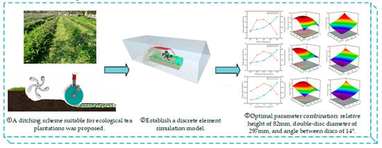
Using EDEM software for the field operation simulation, the motion characteristics of the double-disc colter during trenching were analyzed. The tillage depth stability and working resistance were the key experimental indicators. Single-factor experiments, conducted with a forward speed of 0.5 m/s and a rotary tillage blade speed of 300 r/min, revealed significant impacts of the relative height, double-disc diameter, and angle between the two discs of the double-disc colter on both the tillage depth stability and working resistance. Optimal parameter ranges were determined to be relative heights of 80 mm to 120 mm, double-disc diameters of 280 mm to 320 mm, and angles between the two discs of 10° to 14°.
(2)
A quadratic polynomial model was established through multifactor experiments to correlate the tillage depth stability coefficient and working resistance with the three experimental factors. The optimization of the double-disc colter’s structural parameters yielded optimal operating performance, with a relative height of 82 mm, double-disc diameter of 297 mm, and angle between the two discs of 14°. This resulted in the tillage depth stability reaching 91.64%, with the working resistance reduced to 93.93 N.
(3)
The optimized double-disc colter underwent field validation tests, showing a mere 0.73% deviation between the simulated and field-tested tillage depth stability. The relative error between the simulated and field-tested working resistance was 10.93%, affirming the simulation model’s reliability. Additionally, the device meets the agronomic requirements of hilly eco-tea gardens, and our study offers valuable guidance for the design of trenching equipment for such environments.

Author Contributions

Conceptualization, W.C.; methodology, W.C., J.R. and L.C.; software, W.H.; validation, W.W. and S.Z.; formal analysis, W.C and C.C.; investigation, S.Z. and J.R.; resources, W.C., W.H. and J.R.; data curation, W.C. and W.H.; writing—original draft preparation, W.C.; writing—review and editing, S.Z. and W.W.; visualization, W.C., W.H. and L.C.; project administration, S.Z. and W.W.; funding acquisition, S.Z. All authors have read and agreed to the published version of the manuscript.

Funding

This work was supported by the Guiding Project of the Fujian Provincial Department of Science and Technology (grant number 2022N0009) and Fujian Agriculture and Forestry University (grant number K1520005A05).

Institutional Review Board Statement

Not applicable.

Data Availability Statement

All data are presented in this article in the form of figures and tables.

Acknowledgments

The authors would like to acknowledge the College of Mechanical Electronic Engineering, Fujian Agriculture and Forestry University.

Conflicts of Interest

The authors declare no conflicts of interest.

References

  1. Chen, P.; Guo, W. Ptriple Value Implication and Practice Path of Strengthening the Confidence of Chinese Excellent Culture with Chinese Tea Culture. Trans. Chin. Soc. Tea. Commun. 2021, 48, 780–784. [Google Scholar]
  2. Zhang, X.; Yu, S.; Hu, X.; Zhang, L. Study on Rotary Tillage Cutting Simulations and Energy Consumption Predictions of Sandy Ground Soil in a Xinjiang Cotton Field. Comput. Electron. Agric. 2024, 217, 108646. [Google Scholar] [CrossRef]
  3. Hao, Z.H.; Zheng, E.L.; Li, X.; Yao, H.P.; Wang, X.C.; Qian, S.Y.; Li, W.X.; Zhu, M. Performance Analysis of the Soil-Contacting Parts for no-tillage Planters and Optimization of Blade Structure. Trans. Chin. Soc. Agric. Eng. 2023, 39, 1–13. [Google Scholar]
  4. Fang, H.M.; Ji, C.Y.; Zhang, Q.Y.; Guo, J. Force Analysis of Rotary Blade based on Distinct Element Method. Trans. Chin. Soc. Agric. Eng. 2016, 32, 54–59. [Google Scholar]
  5. Matin, M.A.; Fielke, J.M.; Desbiolles, J.M.A. Torque and Energy Characteristics for Strip-Tillage Cultivation when Cutting Furrows Using Three Designs of Rotary Blade. Biosyst. Eng. 2015, 129, 329–340. [Google Scholar] [CrossRef]
  6. Matin, M.A.; Hossain, M.I.; Gathala, M.K.; Timsina, J.; Krupnik, T.J. Optimal Design and Setting of Rotary Strip-Tiller Blades to Intensify Dry Season Cropping in Asian Wet Clay Soil Conditions. Soil. Tillage Res. 2021, 207, 104854. [Google Scholar] [CrossRef]
  7. Ahmadi, I.A. Torque Calculator for Rotary Tiller Using the Laws of Classical Mechanics. Soil. Tillage Res. 2017, 165, 137–143. [Google Scholar] [CrossRef]
  8. Ma, C.; Meng, H.W.; Zhang, J.; Zhang, C.; Zhao, Y.; Wang, L.H. Research and experiment on the trenching performance of orchard trenching device. Sci. Rep. 2023, 13, 18941. [Google Scholar] [CrossRef] [PubMed]
  9. Zhang, G.; Zhang, Z.; Xiao, M.; Bartos, P.; Bohata, A. Soil-Cutting Simulation and Parameter Optimization of Rotary Blade’s Three-Axis Resistances by Response Surface Method. Comput. Electron. Agric. 2019, 164, 104902. [Google Scholar] [CrossRef]
  10. Yang, Y.W.; Tong, J.; Ma, Y.H.; Jiang, X.H.; Li, J.G. Design and Experiment of Biomimetic Rotary Tillage Blade based on Multiple Claws Characteristics of Mole Rats. Trans. Chin. Soc. Agric. Eng. 2019, 35, 37–45. [Google Scholar]
  11. Xiong, P.Y.; Yang, Z.; Sun, Z.Q.; Zhang, Q.Q.; Huang, Y.Q.; Zhang, Z.W. Simulation Analysis and Experiment for Three-Axis Working Resistances of Rotary Blade based on Discrete Element Method. Trans. Chin. Soc. Agric. Eng. 2018, 34, 113–121. [Google Scholar]
  12. Fiaz, A.; Ding, W.; Ding, Q.; Mubshar, H.; Khawar, J. Forces and Straw Cutting Performance of Double Disc Furrow Opener in No-Till Paddy Soil. PLoS ONE 2015, 10, e0119648. [Google Scholar]
  13. Collins, B.A.; Fowler, D.B. Effect of Soil Characteristics, Seeding Depth, Operating Speed, and Opener Design on Draft Force During Direct Seeding. Soil. Tillage Res. 1996, 39, 199–211. [Google Scholar] [CrossRef]
  14. Wang, Y.; Xue, W.; Ma, Y.; Tong, J.; Liu, X.; Sun, J. DEM and Soil Bin Study on a Biomimetic Disc Furrow Opener. Comput. Electron. Agric. 2019, 156, 209–216. [Google Scholar] [CrossRef]
  15. Zhu, R.X.; Li, C.X.; Cheng, Y.; Yan, X.L.; Li, J.; Shi, Y.P.; Ge, S.Q. Working Performance of Passive Disc Coulter. Trans. Chin. Soc. Agric. Eng. 2014, 30, 47–54. [Google Scholar]
  16. Zhang, S.Q.; Zuo, C.C.; Ma, C.L. The Study on the Model of Disc Coulter Force. Trans. Chin. Soc. Agric. Mach. 1998, S1, 71–75. [Google Scholar]
  17. Bai, X.H.; Li, J.; Lv, C.Y.; Hu, Y.Q. Analysis and Experiment on Working Performance of Disc Coulter for No-Tillage Seeder. Trans. Chin. Soc. Agric. Eng. 2014, 30, 1–9. [Google Scholar]
  18. Hu, H.; Li, H.; Wang, Q.; He, J.; Lu, C.; Wang, Y.; Liu, P. Anti-Blocking Performance of Ultrahigh-Pressure Waterjet Assisted Furrow Opener for No-Till Seeder. Int. J. Agr. Biol. Eng. 2020, 13, 64–70. [Google Scholar] [CrossRef]
  19. Jia, H.L.; Guo, M.Z.; Guo, C.J.; Zheng, J.; Zhang, C.L.; Zhao, J.L. Design of Dynamic Bionic Stubble Cutting Device and Optimization Test of Parameters. Trans. Chin. Soc. Agric. Mach. 2018, 49, 103–114. [Google Scholar]
  20. Lin, J.; Li, B.; Li, B.F.; Niu, J.L.; Qian, W. Parameter Optimization and Experiment on Archimedes Spiral Type of Gap Cutting Disc. Trans. Chin. Soc. Agric. Mach. 2014, 45, 118–124. [Google Scholar]
  21. Zhuang, J.; Jia, H.L.; Ma, Y.H.; Li, Y.; Di, Y.K. Design and Experiment of Sliding-Knife-Type Disc Opener. Trans. Chin. Soc. Agric. Mach. 2013, 44, 83–88. [Google Scholar]
  22. Ye, R.; Ma, X.; Zhao, J.; Liao, J.; Liu, X.; Xi, L.; Su, G. Optimization and Design of Disc-Type Furrow Opener of No-Till Seeder for Green Manure Crops in South Xinjiang Orchards. Agriculture 2023, 13, 1474. [Google Scholar] [CrossRef]
  23. Sugirbay, A.; Zhao, K.; Liu, G.; Hu, G.; Chen, J.; Mustafin, Z.; Iskakov, R.; Kakabayev, N.; Muratkhan, M.; Khan, V.; et al. Double Disc Colter for a Zero-Till Seeder Simultaneously Applying Granular Fertilizers and Wheat Seeds. Agriculture 2023, 13, 1102. [Google Scholar] [CrossRef]
  24. Francetto, T.R.; Alonço, A.D.S.; Brandelero, C.; Machado, O.D.D.C.; Veit, A.A.; Carpes, D.P. Disturbance of Ultisol Soil based on Iteractions between Frrow Oeners and Culters for the No-Tillage System. Span. J. Agric. Res. 2016, 14, e0208. [Google Scholar] [CrossRef]
  25. Karayel, D. Performance of a Modified Precision Vacuum Seeder for No-Till Sowing of Maize and Soybean. Soil. Tillage Res. 2009, 104, 121–125. [Google Scholar] [CrossRef]
  26. Wang, W.; Diao, P.; Jia, H.; Chen, Y. Design and Experiment Evaluation of Furrow Compaction Device with Opener for Maize. Int. J. Agr. Biol. Eng. 2020, 13, 123–131. [Google Scholar] [CrossRef]
  27. Villanueva, P.; Bona, S.; Lostado-Lorza, R.; Veiga, F. Morphological Design of a Bicycle Propulsion Component Using the Hierarchical Analysis Process (AHP). Appl. Sci. 2023, 13, 7792. [Google Scholar] [CrossRef]
Figure 1. Schematic of trenching and fertilizing integrated machine and its components for eco-tea plantation. (a) Overall machine structure diagram; (b) Rotary tillage blade diagram; (c) Double-disc colter diagram. 1. Engine; 2. Transmission system; 3. Control mechanism; 4. Fertilizing device; 5. Double-disc colter; 6. Soil covering mechanism; 7. Depth-limiting wheel; 8. Fertilizer discharge box; 9. Soil deflector plate; 10. Driving wheel; I. Blade holder; II. Trenching blade; ① Fertilizer discharge tube; ② Double-disc colter frame; ③ Disc blade; ④ Soil scraper; ⑤ Compression spring.
Agriculture 14 00704 g001
Figure 2. Schematic of the operational process of the colter. 1. Untilled soil area; 2. Weeds and straw; 3. Rotary tillage blade; 4. Double-disc colter; 5. Tilled soil area; V m is forward speed of the machine; ω is angular velocity of rotary tillage blade; h 0 is vertical distance from the mass point of rotary tillage blade to the ground; h 1 is trenching depth of rotary tillage blade; h 2 is trenching depth of double-disc colter; L 1   is horizontal distance between rotary tillage blade and the double-disc colter’s mass point; L 2   is vertical distance between rotary tillage blade and the double-disc colter’s mass point.
Agriculture 14 00704 g002
Figure 3. Force diagram of the double-disc colter. (a) Force analysis of the double-disc colter. (b) Schematic diagram of the interaction forces between double discs and soil.
Agriculture 14 00704 g003
Figure 4. The trenching process simulated in EDEM. (a) Colter model; (b) Furrow model; (c) Simulation process; 1. Soil deflector plate; 2. Rotary tillage blade; 3. Straw; 4. Double-disc colter; 5. Furrow.
Agriculture 14 00704 g004
Figure 5. Colter experiment in furrow. 1. Test stand cart; 2. Counterweights; 3. Double-disc colter; 4. Tension sensor; 5. Tension sensor detector; 6. Test cart accessory device.
Agriculture 14 00704 g005
Figure 6. EDEM simulation trenching results. (a) Schematic of the working area. (b) Measurement of trench depth. 1. Soil deflector plate; 2. Rotary tillage blade; 3. Double-disc colter; 4. Straw; 5. Working area.
Agriculture 14 00704 g006
Figure 7. The influence of relative height on experimental indicators.
Agriculture 14 00704 g007
Figure 8. Influence of double-disc diameter on experimental indicators.
Agriculture 14 00704 g008
Figure 9. The influence of angle between two discs on experimental indicators.
Agriculture 14 00704 g009
Figure 10. The impact of interaction effects on tillage depth stability. (a) The impact of double-disc diameter and relative height on tillage depth stability. (b) The impact of angle between two discs and relative height on tillage depth stability. (c) The impact of double-disc diameter and angle between two discs on tillage depth stability.
Agriculture 14 00704 g010
Figure 11. The impact of interaction effects on working resistance. (a) The impact of double-disc diameter and relative height on working resistance. (b) The impact of angle between two discs and relative height on working resistance. (c) The impact of angle between two discs and double-disc diameter on working resistance.
Agriculture 14 00704 g011
Table 1. Trenching material model.
Key ComponentMaterialDensity (kg·m−3)Poisson’s RatioShear Modulus (Pa)
Soil deflector plate1566 steel78500.357.8 × 1010
Rotary tiller
Double-disc trencher
Table 2. Contact parameters of the discrete element model.
ParameterValue
Soil density/kg·m−32600
Soil Poisson’s ratio0.42
Soil shear modulus/Pa1 × 106
Straw density/kg·m−3494
Straw Poisson’s ratio0.4
Straw shear modulus/Pa1 × 106
Soil–soil restitution coefficient0.35
Soil–soil static friction coefficient0.55
Soil–soil rolling friction coefficient0.37
Soil–steel restitution coefficient0.6
Soil–steel static friction coefficient0.5
Soil–steel rolling friction coefficient0.3
Straw–steel restitution coefficient0.5
Straw–steel static friction coefficient0.25
Straw–steel rolling friction coefficient0.06
Table 3. Single-factor simulation experiment factor level table.
Experimental Factors
Level CodeRelative Height
x 1 /(mm)
Double-Disc Diameter x 2 /(mm)Angle between Two Discs x 3 /(°)
16026010
28028012
310030014
412032016
514034018
Table 4. Multi-factor simulation experiment factor level table.
Experimental Factors
Level CodeRelative Height
X 1 /(mm)
Double-Disc Diameter X 2 /(mm)Angle between Two Disks X 3 /(°)
1.68213433415
112032014
010030012
−18028010
−1.682662669
Table 5. Multi-Factor Simulation Experiment Design and Results.
RunExperimental FactorsPerformance Indicators
Relative Height
X 1 /(mm)
Double-Disc Diameter
X 2 /(mm)
Angle between
Two Disks
X 3 /(°)
Tillage Depth Stability
Y 1 /(%)
Working
Resistance
Y 2 /(N)
1−1.6820087.0673.5
20−1.682084.2992.1
300091.0198.8
41−1−186.43127.6
500090.85105.7
6−1−1190.0685.7
71.6820086.32179.2
800089.63110.5
900090.36104.6
1000088.97108.9
11−11−187.56107
1200−1.68286.9394.4
13001.68292.6136.6
1411−186.14168.2
1501.682086.16165.6
16−1−1−185.2681.5
1700090.21105.9
1811189.36221.6
191−1188.74140.9
20−11191.28129.2
Table 6. Analysis of Variance for Tillage Depth Stability by Factors.
SourceSquare
Sum
Degree
of
Freedom
Mean
Square
F-Valuep-ValueSignificance
Regression
Model
93.99910.4414.540.0001**
X11.6411.642.290.1615
X23.5813.584.990.0495*
X340.73140.7356.72<0.0001**
X1X21.2711.271.770.2128
X1X31.1211.121.560.2407
X2X30.003610.00360.0050.9449
X1214.65114.5620.40.0011**
X2233.56133.5646.74<0.0001**
X320.0910.090.12530.7308
Residual7.18100.7182
Lack of Fit4.2450.84891.450.348
Error2.9450.5875
Sum101.1719
Note: “**” indicates significance at p < 0.01, “*” indicates significance at p < 0.05.
Table 7. Analysis of variance for factors on working resistance experimental indicators.
SourceSquare
Sum
Degree
of
Freedom
Mean
Square
F-Valuep-ValueSignificance
Regression
Model
26374.7292930.5279.93<0.0001**
X113707.36113707.36373.85<0.0001**
X27215.4717215.47196.79<0.0001**
X31971.1411971.1453.76<0.0001**
X1X2341.911341.919.330.0122*
X1X3203.011203.015.540.0404*
X2X3421.951421.9511.510.0069**
X121164.9311164.9331.770.0002**
X221405.2411405.2438.330.0001**
X32382.931382.9310.440.009**
Residual366.661036.67
Lack of Fit284.53556.913.460.0994
Error82.13516.43
Sum26741.3819
Note: “**” indicates that p < 0.01, and “*” indicates that p < 0.05.
Table 8. Comparison between simulation and field trenching test results.
ParameterTillage Depth Stability (%)Working Resistance (N)
Simulation Testing Value91.6493.93
Field Testing Value92.37104.2
Disclaimer/Publisher’s Note: The statements, opinions and data contained in all publications are solely those of the individual author(s) and contributor(s) and not of MDPI and/or the editor(s). MDPI and/or the editor(s) disclaim responsibility for any injury to people or property resulting from any ideas, methods, instructions or products referred to in the content.

