
Performance Improvement of a Limaçon Gas Expander Using an Inlet Control Valve: Two Case Studies


Institute of Innovation, Science and Sustainability, Federation University Australia, P.O. Box 663, Ballarat, VIC 3353, Australia
*
Author to whom correspondence should be addressed.
Energies 2024, 17(10), 2427; https://doi.org/10.3390/en17102427
Submission received: 18 March 2024
/
Revised: 10 May 2024
/
Accepted: 13 May 2024
/
Published: 18 May 2024
(This article belongs to the Section J: Thermal Management)
Abstract
:Renewable energy-based compact energy-generation systems based on the organic Rankine cycle (ORC) can be employed to meet the ever-growing thirst for affordable and clean energy. The overall performance and effectiveness of ORC systems are constrained by the low efficiency of the gas expander, specifically the positive displacement expander, which is responsible for energy conversion from the working fluid. This low-efficiency scenario can be significantly improved by employing a control valve to regulate and restrict the flow of the working fluid into the expander. A control valve can effectively curve the loss of costly compressed and energized working fluids by allowing them to expand in the expander chamber before discharging through the outlet port. They can thus be used to regulate the amount of energy yield and output power. In this work, two direct drive rotary valves (DDRVs) operated by a stepper motor (SM-DDRV) and rotary solenoid (RS-DDRV) are suggested, and the behavior of the valves is examined. The effect of friction and temperature on the valve response is also studied. Additionally, the effect of inlet control valves on the overall system performance of the limaçon expander is assessed. Thermodynamic properties such as the isentropic efficiency and filling factor are also computed. The effect of leakage due to valve response delay is analyzed at different inlet pressures. The performance indices are compared to the expander performance without any inlet valve. The SM-DDRV setup results in a 14.86% increase in isentropic efficiency and a 220% increase in the filling factor, whereas the RS-DDRV performs moderately with a 2.58% increase in isentropic efficiency and an 80% increase in the filling factor compared to a ported expander. The SM-DDRV provides better performance indices compared to the RS-DDRV and without valve setups. However, the performance of the limaçon expander with the SM-DDRV is sensitive to the inlet pressure and degrades at higher pressure. Overall, the valves proposed in this work present key insights into improving the performance characteristics of gas expanders of ORC systems.
1. Introduction
In this technologically advanced 21st century, we have to endure the rising energy crisis on a global scale. This energy crisis has a twofold aspect. On the one hand, the ever-increased large-scale production of energy in developed countries has escalated the greenhouse effect; on the other hand, the lack of energy and insufficient development in the energy sector in the underdeveloped and isolated sections of the world has widened the gap between these groups. Aiming for net zero emissions while, at the same time, ensuring affordable energy for all will be one of the biggest challenges that we need to address now and in the coming future.
High carbon emissions due to energy production using fossil fuels are primarily contributing to climate change and global warming. The low efficiency of energy conversion processes largely used currently is mainly contributing to this issue. Currently, traditional power-generation methods using fossil fuels have system efficiencies ranging from 30% to 40%. This limitation is attributed primarily to the sub-optimal performance of turbines, boilers, and condensers [1]. However, the adoption of a combined cycle configuration can raise the efficiency to 55% [1]. Nonetheless, approximately 45% of the usable energy that is wasted in the form of heat and remains unrealized could potentially be converted into electricity through appropriate means.
The utilization of low-grade or waste heat can be one approach to curtail energy loss and improve efficiency. Waste heat recovery (WHR) systems can be applied for this purpose where the low-grade sources can be transformed into usable power using the ORC process. Traditional ORCs consist of the following four basic components; expander, condenser, pump, and evaporator, as shown in Figure 1. The ORC cycle starts in the evaporator by heating the organic working fluid in an isobaric process. The heated fluid/vapor is then passed through the expander, where it expands in an isentropic process. During this expansion process, the thermal potential energy converts to mechanical energy and rotates a rotor inside the expander chamber. The expanded fluid is later condensed in the condenser in an isobaric process. Finally, the compressor compresses the fluid to its normal state in an isentropic process, and the cycle continues.
The physical and thermal characteristics of the fluid play a crucial role in the overall performance and efficiency of an ORC system [2]. In the ORC, water, the traditional working fluid in the conventional Rankine cycle, is replaced by organic refrigerants having lower boiling temperatures and pressures [3,4]. Therefore, less heat is required to obtain the compressed vapors for these fluids compared to water [5]. This modification permits the ORC system to operate with low-grade heat. Various working fluids have been used such as R2341a [6], R245fa [7], pentane [8], hexamethyldisloxane [9], R134 [10], cyclopentane [11], and n-heptane [12]. In this study, R245fa is selected as the primary working fluid as it is safer for the atmosphere having a low global warming potential (GWP) of 1030 and a zero ozone depletion potential (ODP) [13].
Accordingly, the ORC–WHR combined systems can be employed in renewable power generators, such as solar or bio-thermal plants, which produce heat in the range of 90–500 °C [14]. ORC–WHR systems can function within that low-temperature range. Operating temperatures as low as 73.3 °C have been reported, presenting a significant advantage for improving the efficiency of various thermal cycles [15,16]. Moreover, ORC–WHR systems prove to be more economical when compared to other similar technologies. For instance, they exhibit approximately 75% and 200% lower investment, operation, and maintenance costs than conventional gasification systems [17]. Recently, numerous ORC-based small-scale systems have been developed, which are suited for domestic applications. These are perfect for residential use as they operate at lower and safer operating temperatures and pressures. For instance, a 1 kWe ORC-based off-grid solar thermal power plant has been built in rural Lesotho, which produced cleaner affordable energy compared to diesel engines (<$0.18/kWh) [18]. Furthermore, these systems can be used as combined heat and power (CHP) systems, providing both electricity and heat using various renewable energy sources [19,20,21]. However, the poor efficiency of expanders currently constrains their more widespread use.
In general, the efficiency of ORC systems typically ranges between 9.6% and 18.1%, contingent on various aspects such as the type of fluids, the expander efficiency, and the operating temperatures [22]. However, the ORC system’s performance is largely influenced by the expander’s isentropic efficiency. In recent times, efforts have been made towards the improvement of expander design and operation for better efficiency. A limaçon expander, which has largely been overlooked in the past due to the technological challenges associated with manufacturing the machine housing and rotor, has recently experienced a revival in the scientific community. For instance, Sultan et al. proposed a method of power generation using heat recovery by employing such expanders [23,24]. However, advances in manufacturing, control, and optimization technologies have now made it more feasible to realize such small-scale power units. Sultan’s work also demonstrated that using a cam-operated inlet control valve could potentially boost the expander’s overall performance by at least 24%. Nevertheless, cam-operated valves have fixed characteristics and lack the flexibility to adapt to varying loads or operating conditions.
In this paper, we propose replacing the cam-operated valve with a control valve. Two different valves actuated by a stepper motor and rotary solenoid, respectively, have been introduced. Both actuators offer a flexible configuration and adaptive controllability, allowing programmable valve operation at specified expander rotor angles. Here, we will assess the performance of both the valves at the inlet of the Limaçon expander to explore their potential in WHR applications. The selection of two different actuators is motivated by their high precision controllability and affordability. A stepper motor is a DC synchronous motor producing discrete precise movements rather than continuous rotation. In contrast, a rotary solenoid is a modification of the linear solenoid, which can produce a fixed angular rotation. Both of the actuators can be operated by applying a sequence of electric pulses producing rotational motion in either the clockwise or anti-clockwise direction. The amplitude and sequence of the input control signal can be controlled to control the movement and speed of the actuators. For this work, a hybrid stepper motor is chosen as they offer comparatively better performance [25]. Both actuators are modeled mathematically and simulated in conjunction with a thermodynamic model of the limaçon gas expander. This study provides a theoretical basis for the usability of control valves for better performance and controllability of a limaçon gas expander and, consequently, the overall ORC system. The study can be progressed further in the future with necessary experiments and the possible implementation of ORC plants with limaçon expanders and the proposed valves.
2. Outline of the Proposed Valve
Figure 2 shows the proposed direct drive rotary valve. The primary part of the valve is the spool, which is actuated by either stepper motors or rotary solenoids. The valve is fit inside the inlet port of the Limaçon expander. The valve is designed in such a way that it is considered normal open (NO) in the absence of any actuation voltage. This is accomplished with the aid of mechanical springs holding the valve at an open position against the differential fluid pressure. This is to ensure that the expander remains operational even in the case of any mechanical or electrical issues disrupting the valve operation.
At the initial NO position of , the working fluid at a pressure (kPa) enters the expander chamber through the valve antechamber, which is at pressure (kPa), as shown in Figure 2a. During closing operation, the actuator generates an electromagnetic torque, (Nm), inducing a clockwise rotation, (rad), of the valve spool with an angular velocity, (rad/s), as shown in Figure 2b. Two mechanical stoppers can be placed at opposite ends at and to ensure stoppage.
3. Mathematical Modeling
In the following subsections, comprehensive mathematical models of both the stepper motor and rotary solenoid valves will be developed. A thermodynamic model of the limaçon to circular gas expander will also be provided.
3.1. Stepper Motor
Stepper motors are a type of electromechanical transmission device capable of producing high-torque specific and incremental motion in reflection with respect to the digital input electric pulses [26]. The input pulses dictate the direction, angle, and speed of rotation. The stepper motors can be classified into three types according to the construction: variable reluctance, permanent magnet, and hybrid [27]. The variable reluctance type has a toothed rotor and stator, whereas in the permanent magnet type, the toothed rotor is replaced by a permanent magnet [27,28]. The hybrid type is a combination of these two, where the rotor is a toothed-type magnet providing higher torque with smaller steps [28,29]. As such, a hybrid stepper motor should be a good candidate as a valve actuator. Now, the hybrid stepper motor will be modeled mathematically. Matsui, Nakamura, and Kosaka pointed out that the electrical domain of a stepper motor can be represented as a simple R-L circuit and accounting for the rate of change of flux linkages as shown in Figure 3a,b [30]. In this study, a two-phase stepper motor is used, whose voltage–current characteristics in the phases a and b can be represented as follows:
where v (volt) is the input voltage, i (amp) is the resulting current through the windings, and R (Ohm), L (H), and (H) are the winding resistance, inductance, and mutual flux linkage, respectively. Substituting the expressions for mutual flux linkages and provided by [31] into Equations (1a) and (1b) gives:
where is the phase resistance, is the phase self-inductance, p is the number of rotor pole pairs, and is the maximum flux linkage. The voltage and currents in the orthogonal static axis can be transformed into a rotating axis using the Park transformation as given in Equation (3) for the ease of analysis [32]. The equivalent circuit for the rotary axis is shown in Figure 4.
where is the Park transformation matrix. Performing this transformation on Equations (2a) and (2b) gives the following expression:
The expressions for the electrical power input to the motor can be utilized to obtain the electromagnetic torque as shown below:
where is the motor copper loss wasted as heat of the conductors, is the magnetic stored energy, and is the mechanical power component producing torque. The electromagnetic torque can, thus, be derived from as:
3.2. Rotary Solenoid
The rotary solenoid actuator is an electromechanical device comparable to a common linear solenoid actuator, where the former generates torque, unlike the linear push–pull force of the latter. In this manuscript, two rotary solenoids, as shown in Figure 5, are used in tandem to operate the valve in both directions. The construction of the rotary solenoid is shown in Figure 6. The linear motion of the plunger is converted to rotary motion by using a ball bearing. The movement of the ball along the races during actuation is shown in Figure 6b. The races are designed in such a way as to produce rapid motion at the start of the stroke and eventually slow down at the stroke end. This is performed to balance the force along the stroke as the downward force pulling the plunger is smaller at the start due to the higher air gap and increases as the air gap becomes smaller at the end of the stroke. When the solenoid coil is energized, a flow of current through it produces a magnetic field around the coil, which creates an induction action in the armature or plunger, producing force.
Considering the solenoid magnetic circuit of Figure 6c with number of turns, the electromotive force due to the flow of current can be written as:
where and are the magnetic field intensity of the core and air gap, respectively; and are the core and air gap length, respectively. As the voltage is applied, the moving core starts to move and the air gap length decreases and becomes minimum at maximum spool displacement or stroke, S. The effective air gap length can, thus, be represented as . The variable inductance can be described as a function of spool displacement, as shown below:
The rate of change of inductance is given by:
The voltage–current relationship can be represented as follows:
3.3. Valve Dynamics
The valve is a rotating mechanical system, which can be described by the torque–friction relations according to Newton’s second law of rotation as follows:
where (Nm) is the external electromagnetic torque generated by the actuators denoted by and for the motor and solenoid, respectively, J () is the total system inertia including the actuator and spool, (Nm) is the frictional torque, (Nm) is the torque corresponding to steady state fluid flow, and (Nm) is the torque due to connected load. For the rotary solenoid valve, another equation should be added to account for the linear motion of the plunger as below:
where M is the total mass of the solenoid actuator and associated valve, is the differential pressure force at the valve spool, and k is the spring constant (N/m) The flow torque is due to the flow of fluid through the valve port. When fluid passes through the valve port, it introduces a flow force on the rotating valve spool. The axial component of this force produces a torque on the spool, which obstructs the movement of the spool. The expression of flow torque is given by Okhotnikov et al. [34] as below:
where is the discharge coefficient, is the discharge velocity coefficient, is the dynamic area of the orifice, r is the radius of the rotating spool from the center of rotation, and is the angle between the radial flow direction and the radius of the rotating spool denoted as the jet angle. Figure 7 shows the variation of the passage area, , which can be expressed as a function of as shown below:
Substituting (16) into (15) gives the expression of flow torque as follows:
where . The flow rate through the orifice as given by Watton [35] is shown below:
Due to factors such as delay in the current buildup, inertia, and friction, the closing or opening of the valve will never be instantaneous. This delay in response will constitute a leakage flow through the orifice. This leakage is significant during the closing operation as the valve is intended to block all fluid flow into the expander. The leakage can be calculated as follows:
where (s) is the time at which the input voltage to the actuators is given and (s) is when the valve has finished its closing or opening cycle. Apart from the delay, different friction losses will also contribute to the overall energy conversion. The total energy loss per expander cycle due to frictions in the valve rotating parts can be calculated as follows:
where (s) is the time in a cycle. Besides friction, the operating temperature plays a vital role in the performance of the actuators. A rise in temperature will result in a rise in the coil resistance of both actuators, which can be calculated using the following well-known equation:
where and are the initial and effective resistance in , C) is the temperature coefficient of resistivity, and C) is the rise in temperature. The increase in resistivity of the copper coil will reduce the current flowing through it and, consequently, reduce the angular displacement.
3.4. System Equations
3.5. Limaçon Positive Displacement Gas Expander
A positive displacement gas expander is an energy converter that converts the potential energy of a compressed fluid into usable mechanical energy by allowing the fluid to expand in an enclosed chamber. They are specially designed to effectively function with a low shaft speed and low-flow-rate working fluids [23]. This is particularly useful in implementing ORC systems with low-grade heat sources. These expanders can be broadly classified as rotary, piston, and reciprocating according to their construction [36]. Limaçon gas expanders are a type of rotary positive displacement expanders where the machines’ housing and rotor are constructed based on the Limaçon curves of the form or in polar coordinates . Figure 8 shows a limaçon expander consisting of a dual-lobe rotor, housing, inlet–outlet ports, and an inlet control valve. The rotor chord with its center at m slides and rotates following the path constituting the base circle. This rotation of the rotor is due to the expansion of the compressed gas as it flows into the chamber through the inlet. An inlet control valve is used to regulate this flow of compressed and costly fluid. Although limaçon-based positive displacement machines have been around for a long time, not much effort has been directed towards their practical application due mainly to their complex design. But, in recent years, with the advancement of manufacturing techniques, this technology can be an innovative tool to address the ever-rising energy demand and utilization of renewable sources.
As the gas expands in each cycle of operation, its volume, v (m3), and density, (kg/m3), change, which can be described by the following nonlinear differential equations:
where (kg) and (kg) are the masses of the fluid at the inlet and outlet, respectively; , , and are the enthalpies in J/kg at the inlet, chamber, and outlet, respectively; T(K) and S are the temperature and entropy inside the chamber, respectively; and (s) is the time in a cycle. Equations (24) and (25) can be solved iteratively until the following condition is met:
where is a small error value. The rate of fluid mass flowing into the chamber is a function of the dynamic passage area, (m2), as defined in (16); the pressure difference across the valve, (kPa); and the fluid density inside the chamber, (kg/m3). This can be represented by the following equation:
where is the rotation of the DDRV. The converted energy due to the expansion of the fluid inside the chamber can be expressed as:
where P (kPa) is the chamber pressure. The isentropic efficiency, , can, thus, be obtained from the ratio of the energy obtained to the maximum obtainable energy as follows:
where (kg/m3) is the fluid density at the inlet and (m3) is the chamber volume when the inlet valve is closed to stop fluid flow. Another important performance index is the filling factor, , which is the ratio of actual mass admitted into the chamber to the mass that could be incorporated into the chamber volume. This is given as follows:
As seen in Equation (27), the rate of mass flow into the expander depends on the valve rotation, , along with the pressure and density of the fluid. Therefore, the expander model should be simulated in conjunction with the DDRV model.
4. Simulation of Actuators
The mathematical models of the proposed DDRVs as described in Equations (22) and (23) are solved analytically to simulate the valve dynamic response. Later, the DDRVs are tested against the thermodynamic model of the limaçon gas expander as described in Section 3.5. For the ease of analysis and clarity, the simulation of the valve–expander system is conducted in terms of the expander rotor angle to study the effect of the proposed DDRVs on various performance indices of the expander.
The introduction of the inlet valve to the gas expander enables it to selectively permit or obstruct the fluid into the chamber. The aim is to control the valve to operate at a certain predefined position of the rotor in its trajectory, as shown in Figure 9. The angular positions of the expander rotor at which the valve closes and opens are referred to as the cutoff and pass angle, respectively.
4.1. Dynamic Response of the Valve
To simulate the operation of the valve in conjunction with the expander rotor angle , the sets of differential equations in (22) and (23) for the stepper motor and rotary solenoid actuators, respectively, are reformulated as shown in (31) and (32). These two sets of differential equations are solved in an iterative manner using Matlab (https://www.mathworks.com/products/matlab.html) with the different parameters provided in Table 1, Table 2 and Table 3. It is necessary to note the dissimilarity between the parameters of the SM-DDRV and RS-DDRV. This is due to the difference in the architecture and operating mechanism between the two actuators. The values are chosen to produce similar angular movements of the valve spool. A later study on the optimization of these valve parameters can yield a better speed of response.
where denotes the angular velocity of the expander rotor.
Both the stepper motor and rotary solenoid actuators are actuated by a voltage input, resulting in a current flow through their windings, as shown in Figure 10a,b. This flow of current produces mechanical movement. The various stages of response due to this current are shown in Figure 11, Figure 12 and Figure 13.
The angular velocity and torque produced in the rotary solenoid actuator are much less compared to the stepper motor actuator, as shown in Figure 11a,b. It can be seen that the stepper motor actuator produces higher torque and angular velocity compared to the rotary solenoid. Thus, the stepper motor actuator is faster in response to the same input voltage. The actuation speed of the rotary solenoid could be increased by increasing the input voltage and its configuration and architecture.
A comparison of the angular displacements for both actuators to the ideal characteristics is shown in Figure 12. Ideally, the valve should operate at the designated cutoff angle (90°) and pass angle (180°) to block and allow the fluid flow, respectively. But, as seen here, both actuators have some delay in responding to the voltage input. For better understanding and ease of depiction, a closing operation of the valve is shown in Figure 12b. It is seen that the valve spool could not attain its maximum rotation instantaneously, but rather, continues rotation throughout the closing cycle. Initially, at the half-closed position, the delay of the SM-DDRV is smaller at ° compared to that of the RS-DDRV (°). At the 75%-closed position, both actuators have a delay of °, but the SM-DDRV slows down afterwards towards the fully closed position, while the delay increases roughly to the closing duty cycle of 90°. The RS-DDRV, on the contrary, maintains a constant delay, and at full-closed position, the delay is °. The delay could be reduced by optimizing one or more of the parameters, including the duty cycle, step angle, and valve orifice diameter. The valve area and the resulting fluid flow rate vary accordingly, as shown in Figure 13. Both the valve area and flow rate variation are faster initially for the SM-DDRV compared to the RS-DDRV, but falter at the later stage.
Effect of Temperature and Friction
The effect of the temperature rise on the valve is studied to find the temperature limit of the actuators. Figure 14 shows the effect of temperature on the peak currents and maximum stroke. As seen in Figure 14a, the current in both actuators decreases as the temperature rises, increasing resistance. At high temperatures, the current will decrease to a value that is unable to produce any effective motion. This limiting temperature is different for the two actuators, as seen in Figure 14b, where 75 °C and 115 °C are the limiting temperatures for the RS-DDRV and SM-DDRV, respectively. However, proper thermal insulation and future optimization could be adopted to increase the temperature limit.
Besides temperature, friction also affects the overall system performance. The energy loss due to rotational and fluid friction at different inlet pressures is shown in Figure 15.
It is seen that frictional losses increase with pressure, and the SM-DDRV has higher frictional losses than the RS-DDRV. However, the losses incurred are negligible compared to the total energy converted, as will be seen in the next section.
4.2. Application of Proposed DDRVs to the Limaçon Expander
The performance of the SM-DDRV and RS-DDRV as the inlet control valves of a limaçon expander is validated. The thermodynamic model of the gas expander with the design parameters as stipulated in Table 4 is utilized for this study. The simulation of the expander for a full operating cycle with and without the proposed DDRVs is performed, and the resulting thermodynamic properties including the temperature, pressure, entropy, and volume in the expander chamber are calculated.
As seen from the pressure–volume (PV) diagram of Figure 16, the area of the PV diagram for SM-DDRV is comparable to the without valve case, but has a major distinction from that of the RS-DDRV, which is much less. The pressure builds up initially and is sustained for some time, but drops around 155 degree due to exposure to the discharge port, as shown in Figure 17a. The pressure build-up is higher for the expander without a valve, accounting for the constant flow through the inlet port. The pressure buildup in the RS-DDRV is much less compared to the SM-DDRV and port operation. The temperature and entropy changes also take place accordingly, as shown in Figure 17b,c. Both the entropy and temperature are high for the RS-DDRV compared to the other two cases, indicating lower energy conversion for this case. The various performance indices including mass flow, filling factor, isentropic efficiency, energy, and power are shown in Figure 18. In the case of the expander without a valve, the energy ( J) and power ( kW) output is highest compared to the other two cases. This is because the fluid flow is not restricted at the inlet port, which is reflected in a higher mass flow ( gm). In the SM-DDRV, the energy ( J) and indicated power ( kW) output are similar to the case of the expander without a valve, whereas the RS-DDRV produces less energy ( J) and power ( kW) compared to the other two cases, which are accountable for its low mass flow rate of gm. In terms of isentropic efficiency and the filling factor, which are two crucial performance indicators of the expansion process, the SM-DDRV has the upper hand with an isentropic efficiency of 63.14% and a filling factor of 0.64. The RS-DDRV also shows improvements in these two indices with an isentropic efficiency of 56.39% and a filling factor of 0.36. The values of these two indices are low in the ported without the valve expander operation with an isentropic efficiency of 54.97% and a filling factor of just 0.21.
4.3. Sensitivity to Inlet Pressure
In the above analysis, the fluid pressure at the inlet is considered constant. However, it is now required to check how the valves react to a changing inlet pressure. The pressure is varied from 800 kPa to 1600 kPa, and the sensitivity of the valves is analyzed. Figure 19a depicts the gas leakage through the orifice due to the delay in valve response while closing.
It is seen that at low pressure of 800 kPa, the SM-DDRV has a minimum leakage of 0.077 L, while the RS-DDRV has a leakage of 0.20 L. However, as the pressure increases to 1000 kPa, the leakage for the SM-DDRV increases considerably to 0.38 L. The leakage continues to increase steadily and reaches a maximum value of 0.42 L at a pressure of 1600 kPa, whereas the RS-DDRV maintains a relatively constant leakage with the pressure increase and reaches a maximum leakage of 0.29 L at 1600 kPa. An increased leakage means an increased fluid flow into the expander chamber, as seen in Figure 19b. At higher pressures, the mass flowing into the chamber will be high if not properly blocked by the valve. The SM-DDRV has a higher leakage at increased pressures, so the mass flow is high in this case, but less than that of the expander with no valve. The mass flow is less for the RS-DDRV as it has lower leakage as compared to the other two cases. The gas leakage affects the performance indices of the expander, as will be seen as follows.
As seen in Equations (29) and (30), the isentropic efficiency and filling factor depend on the amount of mass flowing into the chamber. Figure 20a shows the variation of the isentropic efficiency for different inlet pressures. At low pressure from 800–1000 kPa, the isentropic efficiency for the SM-DDRV is high and reaches a maximum of 63.14%. However, at higher pressures, the efficiency reduces as the mass flow increases. On the contrary, for the RS-DDRV, the efficiency is less at lower pressure, but increases with pressure. The maximum achieved efficiency with the RS-DDRV is 60.63% at 1600 kPa. Figure 20b shows the filling factor at different pressures. As seen above, the SM-DDRV has a higher mass flow compared to the RS-DDRV, so, the filling factor will be high for this valve. However, at higher pressure, the leakage is high, which contributes to a filling factor calculation above 1 as more fluid flow is more than the intended amount. It can be deduced from Figure 20b that the maximum filling factor less than 1 is achieved by the SM-DDRV at 1000 kPa. The filling factor at low pressures with the RS-DDRV is higher than the no-valve case but less than the SM-DDRV; however, it decreases at higher pressures.
5. Results and Discussion
The case studies provided here give insights into improving the process efficiency of the expander. As seen in Figure 12, both the SM-DDRV and RS-DDRV have some delay in response due to the time taken to build up current in the windings and the resultant mechanical displacement of the valve spool. However, the SM-DDRV has a faster response initially compared to the RS-DDRV, but slows down at the end of the opening or closing cycle, which is reflected in its performance indices. At lower pressures of less than 1000 kPa, the SM-DDRV has better performance than the RS-DDRV in improving the isentropic efficiency and filling factor. At 1000 kPa, the SM-DDRV improves the isentropic efficiency by 14.88% and the filling factor by 220% compared to the ported expander. However, at higher pressures, the performance of the SM-DDRV degrades as the leakage increases. Further optimization of both valve parameters should yield better dynamic performance at elevated inlet pressures. Nevertheless, the proposed SM-DDRV valve is preferable at pressures less than 1000 kPa, which improves the overall process efficiency. But, at higher pressures, the RS-DDRV is preferable. The isentropic efficiency of 63.14% achieved with the SM-DDRV is an improvement from the previously reported study conducted by Sultan et al. [24], where they reported an efficiency of 58.67%. This study provides a good theoretical base for future applications of limaçon expanders in ORC-based plants.
6. Conclusions
Enhancing the efficiency of compact and renewable-based power-generation systems, like the one examined here, can significantly contribute to addressing the current energy crisis and reducing the effects of greenhouse gas emissions. The valves proposed in this work hold promise as a valuable instrument for enhancing the operational efficiency of such setups. The effectiveness of the proposed valves has been analyzed theoretically and will be validated by experiments in the future. The mathematical models and simulated outcomes will also offer essential guidelines for the future development and deployment of similar power-generation units. In light of the above comparative studies, the SM-DDRV presents promising results in improving isentropic efficiency and the filling factor. However, the performance degrades at higher inlet pressure, whereas the RS-DDRV has moderate performance at different pressures. The proposed valves can be optimized in future work, which should improve the performance indices further.
Author Contributions
Conceptualization, M.S.H. and I.S.; methodology, M.S.H.; software, M.S.H., T.P. and I.S.; validation, M.S.H.; formal analysis, M.S.H.; investigation, M.S.H. and I.S.; resources, M.S.H., T.P. and I.S.; data curation, M.S.H. and I.S.; writing—original draft preparation, M.S.H. and I.S.; writing—review and editing, T.P. and A.K.; visualization, M.S.H.; supervision, T.P., A.K. and I.S.; project administration, T.P., A.K. and I.S. All authors have read and agreed to the published version of the manuscript.
Funding
This research was supported by Destination Australia and Federation University Research Excellence Scholarships.
Data Availability Statement
The data presented in this study are available upon request from the corresponding author.
Conflicts of Interest
The authors declare no conflicts of interest. The funders had no role in the design of the study; in the collection, analyses, or interpretation of the data; in the writing of the manuscript; nor in the decision to publish the results.
Abbreviations
The following abbreviations are used in this manuscript:
| ORC | organic Rankine cycle |
| DDRV | direct-drive rotary valve |
| SM-DDRV | stepper motor DDRV |
| RS-DDRV | rotary solenoid DDRV |
| WHR | waste heat recovery |
| CHP | combined heat and power |
| GWP | Global Warming Potential |
| ODP | Ozone Depletion Potential |
References
- Putrus, G.; Bentley, E. 20-Integration of distributed renewable energy systems into the smart grid. In Electric Renewable Energy Systems; Elsevier: Amsterdam, The Netherlands, 2016; pp. 487–518. [Google Scholar] [CrossRef]
- Tchanche, B.; Quoilin, S.; Declaye, S.; Papadakis, G.; Lemort, V. Economic Optimization of Small Scale Organic Rankine Cycles. In Proceedings of the 23rd International Conference on Efficiency, Cost, Optimization, Simulation and Environmental Impact of Energy Systems, Lausanne, Switzerland, 14–17 June 2010. [Google Scholar]
- Wei, D.; Lu, X.; Lu, Z.; Gu, J. Performance analysis and optimization of organic Rankine cycle (ORC) for waste heat recovery. Energy Convers. Manag. 2007, 48, 1113–1119. [Google Scholar] [CrossRef]
- Liu, Q.; Lasala, S. Waste heat recovery from fossil-fired power plants by organic rankine cycles. In Organic Rankine Cycles for Waste Heat Recovery-Analysis and Applications; Books on Demand: Norderstedt, Germany, 2019. [Google Scholar]
- Yu, H.; Gundersen, T.; Feng, X. Process integration of organic Rankine cycle (ORC) and heat pump for low temperature waste heat recovery. Energy 2018, 160, 330–340. [Google Scholar] [CrossRef]
- Yamada, N.; Mohamad, M.N.A.; Kien, T.T. Study on thermal efficiency of low- to medium-temperature organic Rankine cycles using HFO1234yf. Renew. Energy 2012, 41, 368–375. [Google Scholar] [CrossRef]
- Li, L.; Ge, Y.; Tassou, S. Experimental Study on a Small-scale R245fa Organic Rankine Cycle System for Low-grade Thermal Energy Recovery. Energy Procedia 2017, 105, 1827–1832. [Google Scholar] [CrossRef]
- Chen, H.; Goswami, D.Y.; Stefanakos, E.K. A review of thermodynamic cycles and working fluids for the conversion of low-grade heat. Renew. Sustain. Energy Rev. 2010, 14, 3059–3067. [Google Scholar] [CrossRef]
- Dai, X.; Shi, L.; Qian, W. Thermal stability of hexamethyldisiloxane (MM) as a working fluid for organic Rankine cycle. Int. J. Energy Res. 2019, 43, 896–904. [Google Scholar] [CrossRef]
- Darvish, K.; Ehyaei, M.A.; Atabi, F.; Rosen, M.A. Selection of Optimum Working Fluid for Organic Rankine Cycles by Exergy and Exergy-Economic Analyses. Sustainability 2015, 7, 15362–15383. [Google Scholar] [CrossRef]
- Guo, J.Q.; Li, M.J.; Xu, J.L.; Yan, J.J.; Wang, K. Thermodynamic performance analysis of different supercritical Brayton cycles using CO2-based binary mixtures in the molten salt solar power tower systems. Energy 2019, 173, 785–798. [Google Scholar] [CrossRef]
- Marion, M.; Voicu, I.; Tiffonnet, A.L. Study and optimization of a solar subcritical organic Rankine cycle. Renew. Energy 2012, 48, 100–109. [Google Scholar] [CrossRef]
- Eyerer, S.; Dawo, F.; Kaindl, J.; Wieland, C.; Spliethoff, H. Experimental investigation of modern ORC working fluids R1224yd(Z) and R1233zd(E) as replacements for R245fa. Appl. Energy 2019, 240, 946–963. [Google Scholar] [CrossRef]
- Tian, H.; Shu, G. 17-Organic Rankine Cycle systems for large-scale waste heat recovery to produce electricity. In Organic Rankine Cycle (ORC) Power Systems; Woodhead Publishing: Shaston, UK, 2017; pp. 613–636. [Google Scholar] [CrossRef]
- Auld, A.; Berson, A.; Hogg, S. Organic Rankine cycles in waste heat recovery: A comparative study. Int. J. Low-Carbon Technol. 2013, 8, i9–i18. [Google Scholar] [CrossRef]
- Holdmann, G. The Chena Hot Springs 400kW Geothermal Power Plant: Experience Gained During the First Year of Operation. Trans. Geotherm. Resour. Counc. 2008, 31, 515–519. [Google Scholar]
- Rentizelas, A.; Karellas, S.; Kakaras, E.; Tatsiopoulos, I. Comparative techno-economic analysis of ORC and gasification for bioenergy applications. Energy Convers. Manag. 2009, 50, 674–681. [Google Scholar] [CrossRef]
- Quoilin, S.; Orosz, M.S.; Lemort, V. Modeling and experimental investigation of an Organic Rankine Cycle using scroll expander for small scale solar applications. In Proceedings of the 1st International Congress on Heating, Cooling, and Buildings, Lisbon, Portugal, 7–10 October 2008. [Google Scholar]
- Kane, M.; Larrain, D.; Favrat, D.; Allani, Y. Small hybrid solar power system. Energy 2003, 28, 1427–1443. [Google Scholar] [CrossRef]
- Wang, X.; Zhao, L.; Wang, J.; Zhang, W.; Zhao, X.; Wu, W. Performance evaluation of a low-temperature solar Rankine cycle system utilizing R245fa. Sol. Energy 2010, 84, 353–364. [Google Scholar] [CrossRef]
- Ksayer, E.B.L. Design of an ORC system operating with solar heat and producing sanitary hot water. Energy Procedia 2011, 6, 389–395. [Google Scholar] [CrossRef]
- Bademlioglu, A.; Canbolat, A.; Yamankaradeniz, N.; Kaynakli, O. Investigation of parameters affecting Organic Rankine Cycle efficiency by using Taguchi and ANOVA methods. Appl. Therm. Eng. 2018, 145, 221–228. [Google Scholar] [CrossRef]
- Sultan, I.A. Optimum design of limaçon gas expanders based on thermodynamic performance. Appl. Therm. Eng. 2012, 39, 188–197. [Google Scholar] [CrossRef]
- Sultan, I.A.; Phung, T.H.; Alhelal, A. Improving Process Efficiency by Waste Heat Recuperation: An Application of the Limaçon Technology. In Sustainability in the Mineral and Energy Sectors; CRC Press: Boca Raton, FL, USA, 2016; pp. 475–498. [Google Scholar] [CrossRef]
- Lai, C.K.; Lin, B.W.; Lai, H.Y.; Chen, G.Y. FPGA-Based Hybrid Stepper Motor Drive System Design by Variable Structure Control. Actuators 2021, 10, 113. [Google Scholar] [CrossRef]
- Zhang, L.; Liu, L.; Shen, J.; Lai, J.; Wu, K.; Zhang, Z.; Liu, J. Research on stepper motor motion control based on MCU. In Proceedings of the 2017 Chinese Automation Congress (CAC), Jinan, China, 20–22 October 2017; pp. 3122–3125. [Google Scholar] [CrossRef]
- Khan, T.A.; Taj, T.A.; Ijaz, I. Hybrid stepper motor and its controlling techniques a survey. In Proceedings of the 2014 IEEE NW Russia Young Researchers in Electrical and Electronic Engineering Conference, St. Petersburg, Russia, 3–5 February 2014; pp. 79–83. [Google Scholar] [CrossRef]
- Hojati, M.; Baktash, A. Design and fabrication of a new hybrid stepper motor with significant improvements in torque density. Eng. Sci. Technol. Int. J. 2021, 24, 1116–1122. [Google Scholar] [CrossRef]
- Acarnley, P.P. Stepping Motors: A Guide to Theory and Practice; IET: London, UK, 2002; p. 63. [Google Scholar]
- Matsui, N.; Nakamura, M.; Kosaka, T. Instantaneous torque analysis of hybrid stepping motor. IEEE Trans. Ind. Appl. 1996, 32, 1176–1182. [Google Scholar] [CrossRef]
- Iqteit, N.A.; Yahya, K.; Makahleh, F.M.; Attar, H.; Amer, A.; Solyman, A.A.A.; Qudaimat, A.; Tamizi, K. Simple Mathematical and Simulink Model of Stepper Motor. Energies 2022, 15, 6159. [Google Scholar] [CrossRef]
- Fitzgerald, A.; Charles Kingsley, J.; Umans, S.D. Electric Machinery; McGraw-Hill: New York, NY, USA, 2003. [Google Scholar]
- Bolden, B.O. Hybrid Computer Simulation of the Dynamic Performance of a Rotary Solenoid. Master’s Thesis, Oregon State University, Corvallis, OR, USA, 1969. [Google Scholar]
- Okhotnikov, I.; Noroozi, S.; Sewell, P.; Godfrey, P. Evaluation of steady flow torques and pressure losses in a rotary flow control valve by means of computational fluid dynamics. Int. J. Heat Fluid Flow 2017, 64, 89–102. [Google Scholar] [CrossRef]
- Watton, J. Fundamentals of Fluid Power Control; Cambridge University Press: Cambridge, UK, 2009. [Google Scholar] [CrossRef]
- Phung, T.; Sultan, I.; Boretti, A. Design of Limaçon Gas Expanders. In Nonlinear Approaches in Engineering Applications: Advanced Analysis of Vehicle Related Technologies; Jazar, R.N., Dai, L., Eds.; Springer International Publishing: Cham, Switzerland, 2016; pp. 91–119. [Google Scholar] [CrossRef]
Figure 1.
Basic arrangement of an ORC process.

Figure 2.
DDRV outline. (a) Open and (b) closed positions.

Figure 3.
Stepper motor equivalent circuit (a) phase a and (b) phase b.

Figure 4.
Stepper motor equivalent circuit (a) d axis and (b) q axis.

Figure 5.
Arrangement of solenoids.

Figure 6.
Rotary solenoid. (a) Schematic diagram of rotary solenoid, (b) armature rotary action, and (c) solenoid magnetic circuit.
Figure 6.
Rotary solenoid. (a) Schematic diagram of rotary solenoid, (b) armature rotary action, and (c) solenoid magnetic circuit.
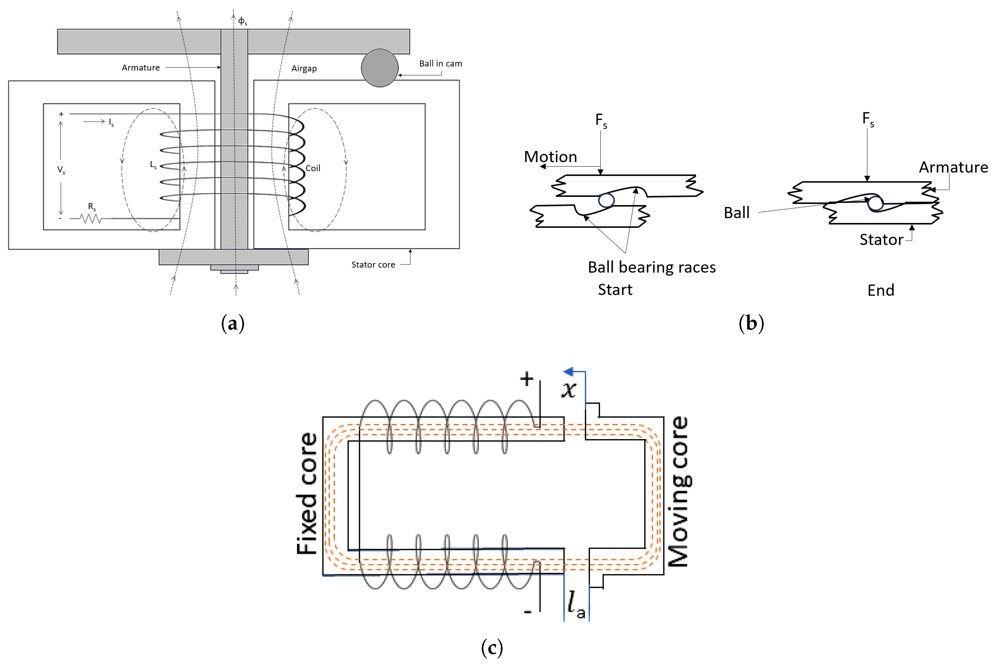
Figure 7.
Dynamic passage area.

Figure 8.
Limaçon expander with inlet valve.

Figure 9.
Valve operating sequence.

Figure 10.
Input (a) phase voltage and (b) phase current.

Figure 11.
Valve response (a) angular velocity and (b) torque produced.

Figure 12.
(a) Valve displacement response and (b) delay.

Figure 13.
Variation of (a) valve area and (b) flow rate.

Figure 14.
Change in (a) peak current and (b) stroke, due to temperature rise.

Figure 15.
Frictional loss.

Figure 16.
PV diagram.

Figure 17.
(a) Pressure, (b) temperature, and (c) entropy in upper and lower chamber.

Figure 18.
Expander outputs: (a) energy, and isentropic efficiency; (b) mass flow, filling factor, and indicated power.
Figure 18.
Expander outputs: (a) energy, and isentropic efficiency; (b) mass flow, filling factor, and indicated power.

Figure 19.
(a) Leakage and (b) mass flow at different inlet pressures.

Figure 20.
(a) Isentropic efficiency and (b) filling factor at different inlet pressures.


Table 1.
Stepper motor data.
| Parameters | Value |
|---|---|
| Number of phases | 2 |
| Phase voltages ( and ) | |
| Step angle | |
| Winding self-inductance () | |
| Winding resistance () | |
| Maximum flux linkage () |
Table 2.
Rotary solenoid data.
| Parameters | Value |
|---|---|
| Applied voltage () | 20 |
| Number of turns () | 500 |
| Coil resistance () | |
| Spring constant (k) | |
| Effective air gap () | m2 |
| Radius of ball bearing races (r) | m |
Table 3.
Valve data.
| Parameters | Value |
|---|---|
| Total mass (M) | |
| Total moment of inertia (J) | 2 |
| Total friction (B) | kgm/ |
| Supply pressure () | 1000 |
| Supply temperature () | 120 °C |
| Valve ante-chamber pressure () | 600 |
| Expander speed | 800 rpm |
| Diameter of orifice () | 25 |
| Diameter of valve shaft () | 15 |
| Discharge velocity coefficient () | 0.98 |
| Discharge coefficient () | 0.65 |
| Jet angle () | 69° |
| Cutoff angle () | 90° |
| Pass angle () | 180° |
Table 4.
Data for the L2C expander.
| Parameters | Value |
|---|---|
| Half of rotor chord length (L) | mm |
| Base circle radius (r) | mm |
| Limaçon aspect ratio () | 0.171 |
| Housing–rotor clearance (C) | mm |
| Clearance ratio () | 0.0153 |
| Design coefficient (a) | 1.73 |
| Depth of rotor housing (H) | mm |
| Fluid type | R245fa |
| Outlet pressure () | 100 |
| Inlet port start angle | ° |
| Inlet port end angle | ° |
| Inlet port length | mm |
| Outlet port start angle | 140° |
| Outlet port end angle | 175° |
| Outlet port length | mm |
Disclaimer/Publisher’s Note: The statements, opinions and data contained in all publications are solely those of the individual author(s) and contributor(s) and not of MDPI and/or the editor(s). MDPI and/or the editor(s) disclaim responsibility for any injury to people or property resulting from any ideas, methods, instructions or products referred to in the content. |
© 2024 by the authors. Licensee MDPI, Basel, Switzerland. This article is an open access article distributed under the terms and conditions of the Creative Commons Attribution (CC BY) license (https://creativecommons.org/licenses/by/4.0/).
Share and Cite
MDPI and ACS Style
Hossain, M.S.; Sultan, I.; Phung, T.; Kumar, A. Performance Improvement of a Limaçon Gas Expander Using an Inlet Control Valve: Two Case Studies. Energies 2024, 17, 2427. https://doi.org/10.3390/en17102427
AMA Style
Hossain MS, Sultan I, Phung T, Kumar A. Performance Improvement of a Limaçon Gas Expander Using an Inlet Control Valve: Two Case Studies. Energies. 2024; 17(10):2427. https://doi.org/10.3390/en17102427
Chicago/Turabian StyleHossain, Md Shazzad, Ibrahim Sultan, Truong Phung, and Apurv Kumar. 2024. "Performance Improvement of a Limaçon Gas Expander Using an Inlet Control Valve: Two Case Studies" Energies 17, no. 10: 2427. https://doi.org/10.3390/en17102427
Note that from the first issue of 2016, this journal uses article numbers instead of page numbers. See further details here.