
Effect of Scanning Electron Beam Pretreatment on Gas Carburization of 22CrMoH Gear Steel
by
Wei Jiang
1,2,†,
Jing-Jing Qu
1,3,†,
Fei Liu
1,2,4,*,
Gao Yue
1,2,4,*,
Lei Zhou
4,
Yu-Cheng Luo
4 and
Hui-Wang Ning
1,2 1
Guangxi Key Laboratory of Manufacturing System & Advanced Manufacturing Technology, Guilin University of Electronic Technology, Guilin 541004, China
2
School of Mechanical and Electrical Engineering, Guilin University of Electronic Technology, Guilin 541004, China
3
School of Mechanical and Electrical Engineering, Guilin University of Aerospace Technology, Guilin 541004, China
4
Postdoctoral Research Station of Guilin Fuda Limited Company, Guilin 541199, China
*
Authors to whom correspondence should be addressed.
†
These authors contributed equally to this work.
Coatings 2024, 14(5), 611; https://doi.org/10.3390/coatings14050611
Submission received: 16 April 2024
/
Revised: 29 April 2024
/
Accepted: 5 May 2024
/
Published: 11 May 2024
(This article belongs to the Section Surface Characterization, Deposition and Modification)
Abstract
:22CrMoH was selected for the gear steel material in this work, and the temperature field change in the scanning electron beam was analyzed to determine the optimal scanning parameters and explored the effect of scanning electron beam pretreatment (Abbreviated as: SEBP) on gas-carburizing (GC) efficiency and organizational properties of gear steel. The results showed that the scanning electron beam caused the material to form a thermally deformed layer 110 μm thick, and it promoted the adsorption of carbon atoms on the surface and their inward diffusion. Under the same gas-carburizing conditions, the carburizing efficiency was improved, and the thickness of the carburized layer increased from 0.78 to 1.09 mm. Furthermore, the hardness of the GC specimens with the SEBP increased from 615 to 638 HV0.05 at 0.1 mm of the sample surface, whereas the hardness of the cross-sectional region decreased gradually, indicating that the scanning electron beam enhanced the adhesion between the carburized layer and matrix zone. A comparative analysis of the microstructures of the GC specimens with and without the SEBP showed that the carbide particles in the surface layer of the samples become smaller and that of volume fraction of residual austenite reduced in size. In terms of the mechanical properties, the surface friction coefficient decreased from 0.87 to 0.46 μ and the GC specimen with the SEBP had a higher cross-sectional hardness gradient. In this way, the amount of wear was reduced from 1.07 to 0.51 mg, which was only 47.7% of the amount of wear of the matrix specimen.
1. Introduction
High-temperature carburization is the main technical method for determining the mechanical properties of “hard outside and tough inside” gears, and gas carburizing is the workpiece in the gas-active medium [1]. In this process, the temperature of the furnace can be adjusted, and the carburization process for the medium of carbon potential can be easily controlled, to ensure that the concentration of carbon and organization of the carburized layer may be regulated [2]. Owing to the advantages of low cost and controllability of furnace temperature and carbon potential, gas carburizing is the main process for batch-carburizing large- and medium-sized helical gear parts [3,4]. In this method, the workpiece must be kept at a high temperature for a long time to obtain the desired thickness of the carburized layer [5]. However, this causes high energy consumption, resulting in an increase in the production cost. Moreover, this process leads to an increased distortion rate of the workpiece and deterioration of the organizational properties of materials. Therefore, the efficiency of the gas carburization for gear steel and the microstructures and mechanical properties of the carburized layer must be improved without raising the carburization temperature. Preoxidation of the surface of the metal and microdeformation via grinding have been shown to improve the surface morphology and microstructure [6,7], which is conducive to subsequent gas carburization of active carbon atoms in the surface layer via adsorption and the atoms’ diffusion into the material.
Fine-crystal catalyzing technology is a catalytic infiltration technology proposed in recent years. The objective is: (i) increase the diffusion channels, such as grain and phase boundaries, by refining the surface grains and tissues, (ii) improve the diffusion rate of carbon atoms at high temperatures and the growth rate of the carburized layer, and (iii) combine the thermal carburizing process and tissue hereditary joint control to determine the microstructure and mechanical properties of the carburized layer [8]. Compared with mechanical grinding, ultrasonic particle bombardment, and high-energy shot peening with laser irradiation, and other surface fine-crystallization techniques [9,10,11], electron beam scanning has a higher energy efficiency, resulting in only minor deformations of the workpiece and a thick fine-crystalline layer. Also, it has the advantage of controlling the structure and properties of the tissue [12,13]. The rapid heating and cooling effect on the surface of the metal under a scanning electron beam leads to changes in surface composition, elemental distribution, phase composition, and organizational structure and forms sub-structures such as nanocrystalline, microcrystalline, and even amorphous layers within the superficial layer. Furthermore, increasing the defect density for the grain boundaries and phase boundaries can significantly improve the hardness of the surface of the substrate, abrasion resistance, and corrosion resistance [14]. A combination of electron beam scanning and fine-crystal catalytic infiltration effect is expected to greatly promote the carburization efficiency of gear steel and regulate the tissue structure and mechanical properties of the carburized layer through tissue heritability [15,16].
This study mainly focuses on the changes in the microstructures and mechanical properties of gear steel after carburization under SEBP. The temperature field change of the scanning electron beam is analyzed by using the software of finite element analysis [17] to determine the optimal scanning parameters. The accuracy of the numerical simulation results usually affects the melting state of the material surface and the changes in the layer organization, wherein the influencing factors include the accelerating voltage [18], beam current magnitude, scanning rate process parameters, elemental distribution, grain size, and microstructure of influence of the regularity. In addition, the appropriate design for carburizing and the quenching–tempering process is studied to examine the morphology, composition, elemental distribution, phase composition, and organization of the carburized layer under the conditions of SEBP [19,20]. The results of the finite element simulation and analysis are conducive to the control of the tissue structure of the carburized layer and optimization of the mechanical properties of 22CrMoH gear steel, which can provide a basis for the feasibility of implementing this work.
2. Implementation of the Research
2.1. Experimental Materials and Methods
The specimens used in this study are 22CrMoH gear steels. The chemical composition of the carburized layer would be greatly affected if the chemical fraction is out of range. Therefore, analyzing the composition of the raw material was necessary. The samples were selected from the raw materials provided by the manufacturer, and their chemical compositions were analyzed by using a direct-reading spectrometer (Table 1). In addition, the continuous cooling curve of 22CrMoH steel revealed the Ac1 temperature of 760 °C, Ac3 temperature of 840 °C, and austenitizing temperature of 870 °C [21]. It implied that the chemical compositions of the experimental specimens and the heat treatment process were in compliance with the requirements of the actual production process.
The initial experimental sample material was a cylindrical specimen having a diameter of Φ70 mm and height of 20 mm. Wire cutting was applied to process the material into a 50 mm × 50 mm × 20 mm rectangular specimen. The surface was polished with 240–2000 mesh sandpaper and then washed in anhydrous ethanol for 15 min under ultrasonic waves to obtain a clean surface. Scanning electron beam experiments were conducted in vacuum by using multifunctional vacuum electron beam equipment.
The SEBP was followed by gas carburization of the specimen through employing the toroidal-gas-carburizing process. The production line of this process was laid out to ensure that the process was automatically implemented on the workpiece from the inlet to the outlet. There are nine control zones for feeding, preoxidation, heating, strong carburization, diffusion, quenching (straight quenching/pressure quenching), cleaning, tempering, and unloading. These steps are listed in Table 2.
Figure 1 presents the heat treatment process curve for 22CrMoH. The specimen was preoxidized in a heating furnace at 450 °C and then preheated in a continuous-gas-heating furnace at 920 °C, to raise the temperature for precarburization. The entire carburization process consisted of three stages. The first stage was strong seepage, where the temperature was 920 °C and the carburizing gas was passed under a carbon potential of 1.15 ± 0.05%. In the second stage, the carburizing-furnace temperature was reduced to 850 °C for the diffusion of the carburizing gas at a carbon potential of 0.8 ± 0.05%. In the third stage, the carburizing gas was passed in a protective atmosphere at a carbon potential of 0.8 ± 0.05% under heat preservation at 850 °C. At the end of the carburization process, the gears were immersed directly into a quenching oil bath at 90 °C using a pusher device to quench them and achieve the adequate hardness and strength-enhancing organization. Finally, the gears were tempered in a tempering furnace at 190 °C to increase surface hardness and reduce residual stresses.
The cross-sectional surface, etched with 4% ethanol nitric acid solution, and core of the specimen were examined to ascertain the cross-sectional metallographic and core organizations, carburite grade, and thickness of the percolated layer. The surface of the specimen after SEBP was observed by scanning electron microscopy, and the phase composition was analyzed by X-ray diffraction (XRD). The hardness gradient of the cross-sectional surface and the surface abrasion resistance of the specimen were measured by conducting a mechanical property test. The experimental equipment was a metallographic microscope, a scanning electron microscope, an X-ray diffractometer, an energy-dispersive spectrometer, a digital Vickers hardness tester, and a friction and wear tester.
2.2. Numerical Simulation Model of the Scanning Electron Beam
The electron beam was focused by an electromagnetically induced mirror to form a beam with high energy density. The surface of the workpiece was accurately scanned by adjusting the scanning parameters, such as scanning speed and current. The electron beam impinged on the surface of the workpiece in the scanning area, causing the local temperature to rise. The energy of the high-energy electron beam was rapidly converted into thermal energy, leading to the melting and evaporation of the local material on the surface of the workpiece, wherein a thermal action causes the changes in surface organization, such as grain refinement and phase transformation. Gaussian surface heat sources are very common in specialty processing, especially in electron beam welding, electron beam cladding, and the scanning electron beam process, as shown in Figure 2. The scanning electron beam process heat source is Gaussian normal distribution, its heat flow density distribution is not uniform, near the center of the spot energy distribution is high, away from the center of the spot low energy. Therefore, this thesis chooses to use Gaussian surface heat source to simulate the law of temperature change and experimentally explore its surface modification [22].
Pavelic. V [23] proposed a Gaussian surface heat source model with a power density given as:
where is the surface heat flow density at the upper point of the radius, is the maximum heat density of the Gaussian heat source, is the heat flow coefficient, and is the distance between any point in the horizontal plane and the center. The total power of the scanning electron beam on the specimen is:
The actual power of the scanning electron beam is:
where is the voltage of the scanning electron beam, and is the accelerating current of the scanning electrons. The heat transfer efficiency of the scanning electron beam on the specimen surface is 0.95; therefore, the effective power is:
For the scanning electron beam, the effective range of energy is 95% cent, and the heat flow coefficient () is:
The scanning is the electron beam moving in the horizontal direction on the surface of the specimen, and its arbitrary time coordinate is , is a fixed value, is the scanning speed, and is the action time. The distance () from any point in the scanning area to the center of the electron beam spot is:
In summary, the Gaussian heat source numerical model for the scanning electron beam is obtained as:
To ensure the best experimental scanning parameters, such as the specific parameters presented in Table 3, COMSOL finite element analysis software was used for simulation in the scanning electron beam experiment. In the analysis of the transient temperature field of the scanning electron beam on the 22CrMoH steel surface, an electron beam current of 5 mA, scanning electron beam speed of 250 mm/min, spot radius of 5 mm, and maximum specimen surface temperature of 1960 K (between the austenitizing and melting temperatures) were the most suitable compared with other groups of parameters. Therefore, the simulation results obtained from this group of experimental parameters were used for the analysis.
Figure 3 shows the cloud diagrams of the temperature field distribution at various stages of the scanning process. Figure 3a presents the temperature field distribution at t = 0.5 s. When the heat source was loaded onto the surface of the test block, its temperature increased rapidly to 1950 K, which is higher than the Ac3 temperature of the 22CrMoH steel [21]. Figure 3b,c depicts that the peak temperature of the surface of the test block remains stable at approximately 1880 K at t = 3–9 s, and this could be approximated to be the quasi-steady-state stage. Figure 3d shows the temperature field distribution cloud diagram when the heat source moved to the tail of the model, the temperature of the model surface was no longer as stable as in the middle at this stage, as the heat source reaches the model boundary, the continuous absorption of heat made the overall temperature of the model increase, so that the heat accumulates in the tail of the model, and the peak temperature has risen to 1960 K, and at t = 12 s, the first half of the heat source has left the model, which results in the temperature starting to drop, the first half of the heat source has left the model, causing the temperature drop to 1750 K. With most of the heat source leaving the surface of the model, the temperature has dropped to 1080 K at t = 12.5 s.
Figure 4 shows the temperature field distribution of the scanning electron beam and the cooling stage. The cooling rate of the specimen increases after scanning with the electron beam and then decreases gradually. Therefore, choosing a suitable cooling interval was necessary. An interval of 0.5 s was selected for this simulation. Figure 4a shows that the peak surface temperature immediately decreases from 1750 K to 1080 K at the cooling time of t = 12.5 s, i.e., the surface temperature of the specimen decreases by 690 K within 0.5 s, and the cooling rate reaches 1380 K/s. As the simulation process was conducted in vacuum, the surface of the 22CrMoH steel was free from the influence of gases and impurities during the scanning and cooling processes and generated a large amount of martensite [17]. Figure 4b,c reveal that the cooling rate of the surface temperature of the specimen decreases with increasing time.
3. Analysis of Experimental Results
3.1. Surface Morphology and Surface Roughness of Scanned Electron Beam Layers
After the SEBP was performed, the surface of the specimen was no longer flat and smooth. Numerous distinct pits appeared, and the microstructure of the surface was altered, as shown in Figure 5. Evaluation of the surface roughness of the specimen indicated that the roughness increased from 0.182 to 4.676 μm, as shown in Figure 6. The increased surface roughness was conducive to the enhancement of the carburization process for carbon atoms on the surface. The organizational morphology of the cross section of the specimen after scanning could be divided into the melt, heat-affected, and matrix zones, as shown in Figure 7. Owing to the homogeneous heat distribution caused by the scanning electron beam in the processed area, the surface heat could rapidly dissipate downwards through the matrix [24,25].
3.2. Cross-Sectional Hardness after SEBP
Figure 8 shows the curve for the cross-sectional hardness of the specimen after scanning with the electron beam. The surface layer of the specimen was found to be strengthened, i.e., the surface hardness increases noticeably and is 89 HV greater than that of the substrate. However, the hardness in the region having a thickness of ~110 μm increases to different degrees, indicating that the scanning electron beam caused thermal deformation of the surface layer [26]. The microhardness, degree of deformation, and density of dislocations were higher at a distance closer to the surface, as shown in Figure 9. As the distance from the surface increased, the microhardness decreased slowly and reached the non-deformed region, where the hardness was the same as that of the matrix.
3.3. Microstructure Analysis
As can be seen in Figure 10a, the carbide particles of the SEBP specimens become reduced in size and that of austenite decreased and martensite is entirely class IV acicular. As the scanning electron beam roughened the surface and promoted the adsorption of C atoms on the surface, the carburite organization of the specimen increased close to the surface. The rapid heating and cooling of the scanning process resulted in the transformation of the austenite surface of the specimen into martensite [3]. This affected the organizational hereditary properties of the gas carburization, leading to a decrease in the volume fraction of austenite in the SEBP specimen. Figure 10b shows that the specimens with the SEBP showed insignificant free ferrite organization, which indicated that the scanning electron beam improved the organization at the heart for gas carburization. This complies with the need to limit the free ferrite content within the interface region of the heart adjacent to the carburized layer, especially for gear steel materials [27]. Figure 10c shows the depth of the carburized layer of the specimen, which increased in the same region for the SEBP specimen owing to the improved hardenability of the 22CrMoH steel by electron beam scanning [28,29], which enhanced the carburizing efficiency.
3.4. XRD and Energy-Dispersive Spectroscopy (EDS) Analysis
The XRD patterns of the GC specimens with and without SEBP are displayed in Figure 11. The carburized surface layer was mainly composed of the Fe-C phase [30], although the diffraction peaks of Fe3C are present in both samples. The XRD patterns showed diffraction peaks of crystal surfaces (110), (20 → 0), and (211) of both GC specimens, and the diffraction angles of the peaks are 44.3°, 64.4°, and 81.9°, respectively. The peaks of the Fe-C phase on the surface of the carburized specimens with the SEBP were enhanced. This is consistent with the microstructure of the cross-sectional surface.
To investigate the elemental distribution of GC specimens under SEBP conditions, an elemental analysis of 22CrMoH steel was performed [31]. Three probes were set up for EDS scanning of the three regions, namely, the melt zone, the heat-affected zone, and the matrix. The elemental species and contents after scanning are shown in Figure 12. The results showed that the weight percentage of carbon element in the melt zone reached 13.87%, which is much higher than that of 22CrMoH steel, and the content of carbon element in the three zones gradually decreased as a gradient until the change is uniform. This indicated that the organization morphology changed significantly during the treatment. In addition, a distinct aggregation of carbon occurs in the scanned layer [32,33].
3.5. Effect of Microhardness and Wear Resistance
Figure 13 shows the cross-sectional microhardness of GC specimens with and without SEBP. The hardness decreases gradually, cross-sectional hardness of the specimen increases, and the hardness gradient decreases slowly. In addition, under the same conditions of the gas-carburizing process, a greater depth of the carburized layer is obtained. When the depth of the carburized layer increases from 0.78 mm to 1.09 mm, the carburizing efficiency increases by almost 39%. The depth of the carburized layer is determined by its distance from the surface at a hardness of 550 HV0.05.
Figure 14 shows the surface friction coefficient of GC specimens with and without SEBP. It was observed that the surface friction coefficient of the SEBP sample was lower than that of the original specimen. The trend followed was an increase of 0.7 μ and then a gradual decrease to 0.46 μ. The surface friction coefficient of the original carburized specimen was stable at approximately 0.87 μ with a reduction of 44%. After the test, the wear amount was measured with an analytical balance, and for the GC with SEBP specimens, it was found to be 0.51 mg, whereas that of the GC specimens without SEBP was 1.07 mg. Thus, the wear amount of the specimens with SEBP was 47.7% on that of the matrix specimens. It has been shown that the coefficient of friction is associated with the size of carbide particles on the material surface [34,35]. The smaller size of carbide particles in gas-carburized specimens under scanning electron beam pretreatment, which are the main hard abrasive particles during frictional wear, results in a lower coefficient of friction for the specimen compared to that of direct carburization of the substrate.
3.6. Enhanced Carburization and Strengthening Mechanism Analysis
The results of the foregoing analyses showed that the gas-carburizing efficiency increased significantly after SEBP under the same conditions. In addition, the surface hardness of the GC specimens increased after SEBP, whereas the hardness gradient of the cross section decreased more slowly, indicating that SEBP improved the bonding force between the carburized layer and substrate [18,36]. Combining the effects of SEBP on the surface morphology and cross-sectional hardness of the specimens confirms that the pretreatment improves the efficiency and performance of gas carburizing by the following mechanisms:
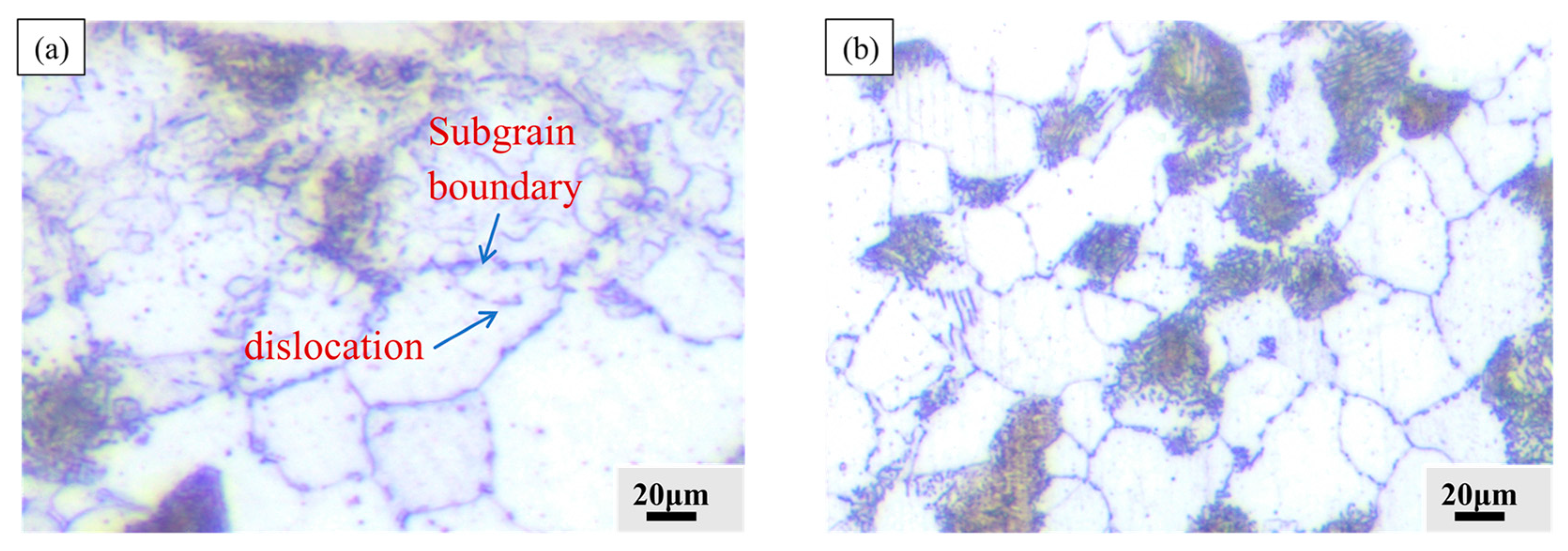
- The SEBP formed a 110 μm thick plastic deformation layer on the surface of the specimen. As shown in Figure 15a, numerous crystal defects, especially dislocations and subcrystalline boundaries, are found in the deformation layer. The rate of diffusion of active carbon atoms along the crystal defects was substantially higher than that in the body. Therefore, the crystal defects formed by the plastic deformation layer of the surface are conducive to the rapid diffusion of active carbon atoms adsorbed on the surface into the substrate [39,40]. In the process of gas carburization, the formation of the carburized layer mainly depended on the surface adsorption and inward diffusion of activated carbon atoms, so that the surface layer had high carburization and carbon concentration.
4. Conclusions
In this study, the gas-carburizing process for 22CrMoH gear steel was optimized, and a scanning electron beam was used for pretreatment. The following conclusions were drawn on the effect of the scanning electron beam on gas carburization and the principle of action:
- (1)
- The SEBP increased the surface roughness of the specimen from 0.182 to 4.676 μm, which was conducive to the adsorption of active carbon atoms on the surface during gas carburization. In addition, a deformation layer with a thickness of approximately 110 μm was formed on the specimen after SEBP, and the microhardness of the cross-sectional surface was improved, which aided the inward diffusion of carbon atoms during carburization.
- (2)
- The scanning electron beam improved the gas-carburizing efficiency, and under the same conditions, the grain refinement effect was more evident, the properties of the tissue were improved, the thickness of the carburized layer increased from 0.78 to 1.09 mm, and the carburizing efficiency improved by 39%.
- (3)
- The Fe-C phase diffraction peaks of the carburized sample with SEBP were enhanced. The EDS elemental analysis showed that the tissue morphology changed significantly during the SEBP, and carbon aggregation appeared in the scanned layer.
- (4)
- The GC specimen with the SEBP had a higher cross-sectional hardness gradient. Its friction coefficient was reduced from approximately 0.8 μ to almost 0.45 μ, and the wear amount of the specimens with SEBP was 47.7% of that of the matrix specimens.
Author Contributions
Conceptualization, F.L. and G.Y.; Methodology, J.-J.Q. and F.L.; Software, J.-J.Q.; Validation, L.Z. and Y.-C.L.; Investigation, W.J.; Resources, H.-W.N.; Data curation, W.J.; Writing—original draft, W.J.; Writing—review & editing, F.L. and G.Y.; Supervision, H.-W.N. All authors have read and agreed to the published version of the manuscript.
Funding
This research was funded by [Guangxi science and technology project key research and development project] grant number [GUIKE AB24010208], [Guangxi Natural Science Foundation] grant number [2021GXNSFBA196038], [Guangxi Key Laboratory of Manufacturing System & Advanced Manufacturing Technology] grant number [23354S012], [China Postdoctoral Science Foundation] grant number [2022MD713742 and 2022M710920]. And [the Key Research and Development Projects of Guilin City] grant number. [20220106-1].
Institutional Review Board Statement
Not applicable.
Informed Consent Statement
Not applicable.
Data Availability Statement
Data are contained within the article.
Conflicts of Interest
Authors Fei Liu, Gao Yue, Lei Zhou and Yu-Cheng Luo were employed by the Postdoctoral Research Station of Guilin Fuda Limited Company. The remaining authors declare that the research was conducted in the absence of any commercial or financial relationships that could be construed as a potential conflict of interest.
References
- Raza, M.A.; Asgar, H.; Abdullah, A.; RAhmad, R.; Inam, A.; Ghauri, F.A.; Ghauri, F.A. Carburising of Low-Carbon Steel Using Carbon Black Nanoparticles. Arab. J. Sci. Eng. 2016, 41, 4661–4667. [Google Scholar] [CrossRef]
- Kumar, V.; Kumar, A.; Kumar, S.; Sarangi, S. TVMS calculation and dynamic analysis of carburized spur gear pair. Mech. Syst. Signal Process. 2022, 166, 108436. [Google Scholar] [CrossRef]
- Asahi, N.; Takeuchi, H.; Funaki, Y.; Pin, K.K.; Urao, R. Effect of gas flow on ion carburizing of steel. J. Phase Equilibria Diffus. 2009, 30, 235–241. [Google Scholar]
- Wolowiec-Korecka, E.; Korecki, M.; Sut, M.; Brewka, A.; Kula, P. Calculation of the Mixture Flow in a Low-Pressure Carburizing Process. Metals 2019, 9, 439. [Google Scholar] [CrossRef]
- Lee, H.Y.; Lee, K.H. Effects of Carburizing Process on Sliding wear Behavior of Carburized SCM420H Steel. Tribol. Lubr. 2020, 36, 18–26. [Google Scholar]
- Tang, L.; Mao, C.J.; Jia, W.J.; Wei, K.X. The effect of novel composite pretreatment on performances of plasma nitrided layer. J. Mater. Res. Technol. 2020, 9, 9531–9536. [Google Scholar] [CrossRef]
- Yu, T.B.; Li, C.; Zhang, D.X.; Wang, W.S.; Zhang, Y.F.; Butle, D.L.; Wang, J.; Yui, A.; Zhou, L. Study on the Simulation of Grinding Burn. Adv. Abras. Technol. XV 2012, 565, 58–63. [Google Scholar] [CrossRef]
- Miao, B.; Chai, Y.T.; Wei, K.X.; Hu, J. A novel duplex plasma treatment combining plasma nitrocarburizing and plasma nitriding. Vacuum 2016, 13, 54–57. [Google Scholar] [CrossRef]
- Tang, L.; Jia, W.J.; Hu, J. An enhanced rapid plasma nitriding by laser shock peening. Mater. Lett. 2018, 231, 91–93. [Google Scholar] [CrossRef]
- Xu, J.L.; Yang, W.L.; Niu, L.; Dan, X.M.; Kang, C.H.; Ma, B.X. The Research Progress of Nanoparticles Surface Modification by Using Mechanochemical Method. In Micro-Nano Technology XVII-XVIII, Proceedings of the 17th–18th Annual Conference and 6th–7th International Conference of the Chinese Society of Micro-Nano Technology; World Scientific: Singapore, 2018; pp. 250–255. [Google Scholar]
- Khun, N.W.; Trung, P.Q.; Butler, D.L. Mechanical and Tribological Properties of Shot-Peened SAE 1070 Steel. Tribol. Trans. 2016, 59, 932–943. [Google Scholar] [CrossRef]
- Yu, J.; Wang, R.; Wei, D.Q.; Meng, C.G. Effect of different scanning modes on the surface properties of continuous electron beam treated 40CrMn steel. Nucl. Instrum. Methods Phys. Res. Sect. B Beam Interact. Mater. At. 2020, 467, 102–107. [Google Scholar] [CrossRef]
- Valkov, S.; Ormanova, M.; Petrov, P. Electron-Beam Surface Treatment of Metals and Alloys. Tech. Trends Met. 2020, 10, 1219. [Google Scholar]
- Matsumoto, T.; Okumura, Y.; Ichimura, M.; Nakamura, H.; Honda, K.; Shibahara, M.; Hirano, T.; Yamada, H.; Tanaka, R.; Sakai, I.; et al. Surface Modification and Adhesion Mechanism of Isotactic Polypropylene with Low-Energy Electron-Beam Treatments. Langmuir 2020, 36, 10846–10852. [Google Scholar] [CrossRef] [PubMed]
- Kim, D.M.; Kim, J.; Park, S.S.; Park, H.W.; Ki, H. Surface modification of the patterned Al6061/SUS304 metal plates using the large electron beam. Appl. Surf. Sci. 2012, 261, 458–463. [Google Scholar] [CrossRef]
- Kim, J.; Kim, J.S.; Kang, E.G.; Park, H.W. Surface modification of the metal plates using continuous electron beam process (CEBP). Appl. Surf. Sci. 2014, 311, 201–207. [Google Scholar] [CrossRef]
- Zhao, G.H.; Zhang, Y.; Zhao, H.; Li, J.; Li, H.Y.; Ma, L.F. Study on the process optimization and wear resistance of electron beam cladding AlCoCrFeNi coating on 253MA austenitic stainless steel surface. Mater. Charact. 2023, 205, 113341. [Google Scholar] [CrossRef]
- Valkov, S.; Parshorov, S.; Andreeva, A.; Rabadzhiyska, S.; Nikolova, M.; Bezdushnyi, R.; Petrov, P. Influence of beam power on the surface architecture and corrosion behavior of electron-beam treated Co-Cr-Mo alloys. Nucl. Instrum. Methods Phys. Res. Sect. B Beam Interact. Mater. At. 2021, 494–495, 46–52. [Google Scholar] [CrossRef]
- Zhang, N.; Guo, S.; He, G.N.; Jiang, B.; Zhou, L.Y.; Chen, Y.; Liu, Y.Z. Failure analysis of the carburized 20MnCr5 gear in fatigue working condition. Int. J. Fatigue 2022, 161, 10938. [Google Scholar] [CrossRef]
- Ye, X.M.; Wu, J.Q.; Zhu, Y.L.; Hu, J. On the role of chemical banding and austenite grain size in microstructure evolutions and phase transformation kinetics of gear steels. Vacuum 2014, 110, 74–744. [Google Scholar] [CrossRef]
- Zhao, Y.; Chen, Y.; Zuo, X.; Yu, W.; Qiu, L.; Luo, Z.; Sun, J. On the role of chemical banding and austenite grain size in microstructure evolutions and phase transformation kinetics of gear steels. Constr. Build. Mater. 2022, 356, 129305. [Google Scholar] [CrossRef]
- Abdi, R.; Tunç, C. Pseudo symmetry curvature conditions on submanifolds of conformal Kenmotsu manifolds. Nonlinear Stud. 2022, 29, 457–476. [Google Scholar]
- Pavelic, V. Experiment and computed temperature histories in gas tungsten-arc welding of thin plates. Wdlding Jourmal Res. Suppl. 1968, 48, 206–305. [Google Scholar]
- Song, L.; Gu, X.M.; Sun, F.; Hu, J. Reduced internal oxidation by a rapid carburizing technology enhanced by pre-oxidation for 18CrNiMo7-6 gear steel. Vacuum 2019, 160, 210–212. [Google Scholar] [CrossRef]
- Chen, X.D.; Feng, S.; Wang, L.W.; Tang, R.; Zhang, F.; Ming, S.L.; Cai, Z.B. Effect of QPQ on the fretting wear behavior of TP316H steel at varying temperatures in liquid sodium. J. Nucl. Mater. 2022, 562, 153583. [Google Scholar] [CrossRef]
- Wang, S.K.; Cai, W.; Li, J.C.; Wei, W.; Hu, J. A novel rapid DC plasma nitriding at low gas pressure for 304 austenitic stainless steel. Mater. Lett. 2013, 105, 47–49. [Google Scholar] [CrossRef]
- Peng, T.T.; Dai, M.Y.; Cai, W.; Wei, W.; Wei, K.X.; Hu, J. The enhancement effect of salt bath preoxidation on salt bath nitriding for AISI 1045 steel. Appl. Surf. Sci. 2019, 484, 610–615. [Google Scholar] [CrossRef]
- Li, D.; Wu, J.Q.; Miao, B.; Zhao, X.B.; Mao, C.J.; Wei, W.; Hu, J. Enhancement of wear resistance by sand blasting-assisted rapid plasma nitriding for 304 austenitic stainless steel. Surf. Eng. 2019, 36, 524–530. [Google Scholar] [CrossRef]
- Batalha, G.F.; Silva, L.C.; Coelho, R.S. Mechanical properties characterization of Ti-6Al-4 V grade 5 (recycled) additively manufactured by selective electron beam melting (EB-PBF). Eng. Fail. Anal. 2024, 157, 107892. [Google Scholar] [CrossRef]
- Yang, Z.Y.; Wei, J.L.; Liu, T.; Liu, S.; Fang, D.L.; Li, Z.Q. Influence of carbon layer hardness characteristics on RCF performance of carburized bearing steel and optimization of heat treatment process. Eng. Fail. Anal. 2024, 160, 108164. [Google Scholar] [CrossRef]
- Xiao, N.; Hui, W.J.; Zhang, Y.J.; Zhao, X.L.; Chen, Y.; Dong, H. High cycle fatigue behavior of a low carbon alloy steel: The influence of vacuum carburizing treatment. Eng. Fail. Anal. 2020, 109, 104215. [Google Scholar] [CrossRef]
- Gupta, A.; Bennett, C.J.; Sun, W. The role of defects and characterisation of tensile behaviour of EBM Additive manufactured Ti-6Al-4V: An experimental study at elevated temperature, Engineering. Fail. Anal. 2021, 120, 105115. [Google Scholar] [CrossRef]
- Dwivedi, P.K.; Sivateja, C.; Rai, A.K.; Ganesh, P.; Basu, A.; Dutta, K. A comparative assessment of the effects of laser shock peening and ultrasonic shot peening on surface integrity and ratcheting fatigue performance of HSLA steel. Int. J. Fatigue 2023, 176, 107902. [Google Scholar] [CrossRef]
- Jeong, D.H.; Erb, U.; Aust, K.T.; Palumbo, G. The relationship between hardness and abrasive wear resistance of electrodeposited nanocrystalline Ni–P coatings. Scr. Mater. 2003, 48, 1067–1072. [Google Scholar] [CrossRef]
- Li, J.; Men, S.W.; Zhang, Z.; Yang, Y.; Sun, Y.; Ding, J.C.; Wang, Q.M. Structural, mechanical, and tribological properties of GLC film on a nitrided layer prepared in a glow-discharge plasma nitriding system. Vacuum 2021, 193, 110543. [Google Scholar] [CrossRef]
- Hirata, T.; Yamaguchi, T.; Yokoyama, Y.; Hoshino, H. Surface modification by high-speed laser gas carburization in low-alloy steel. Mater. Lett. 2020, 280, 128586. [Google Scholar] [CrossRef]
- Wang, J.T.; Qu, S.G.; Shao, H.T.; Hu, X.F.; Guo, B.; Li, X.Q. Ultra-high fatigue propertyand fracture mechanism of modified 20CrMoH steel by gas carburizing technology combined with shot peening treatment. Int. J. Fatigue 2022, 165, 107221. [Google Scholar] [CrossRef]
- Konno, T.; Kato, T.; Yanagida, T.; Inaba, H.; Hirata, Y.; Akasaka, H.; Ohtake, N. Characterization of carburized layer on low-alloy steel fabricated by hydrogen-free carburizing process using carbon ions. Diam. Relat. Mater. 2023, 135, 109816. [Google Scholar] [CrossRef]
- Zhao, G.H.; Zhang, P.; Li, J.; Zhang, Z.; Li, H.Y.; Ma, L.F. Effects of different scannin speeds on microstructure evolution and tribological properties of Inconel 718 alloy vacuumelectron beam surface modification. Mater. Today Sustain. 2024, 25, 100613. [Google Scholar] [CrossRef]
- Li, X.; Wang, R.; Zhang, H.; Xin, Z.; Guo, J.; Dong, Y. Study on micro—Melt polishing and strengthening mechanism of scanning electron beam surface. Nucl. Instrum. Methods Phys. Res. Sect. B Beam Interact. Withmaterials At. 2021, 504, 58–63. [Google Scholar] [CrossRef]
Figure 1.
Carburizing process curve of 22CrMoH gear steel.

Figure 2.
Gaussian surface heat source model.

Figure 3.
Cloud diagram of the temperature field distribution of the scanning electron beam: (a) t = 0.5 s, (b) t = 3 s, (c) t = 6 s, (d) t = 9 s, (e) t = 12 s, (f) t = 12.5 s.
Figure 3.
Cloud diagram of the temperature field distribution of the scanning electron beam: (a) t = 0.5 s, (b) t = 3 s, (c) t = 6 s, (d) t = 9 s, (e) t = 12 s, (f) t = 12.5 s.

Figure 4.
Cloud diagram of the cooling field distribution of the scanning electron beam: (a) t = 12.5 s, (b) t = 13 s, (c) t = 14 s.
Figure 4.
Cloud diagram of the cooling field distribution of the scanning electron beam: (a) t = 12.5 s, (b) t = 13 s, (c) t = 14 s.

Figure 5.
Surface morphology of the specimen after scanning electron beam.
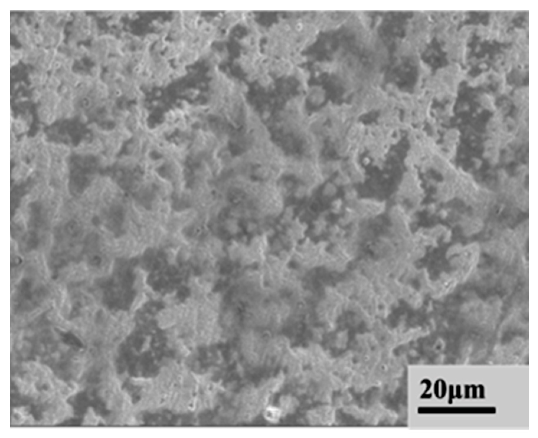
Figure 6.
Specimen surface roughness. (a) Scanning electron beam specimens; (b) matrix.

Figure 7.
Three regions of the specimen cross section after electron beam scanning. (a) Metallographic microscopy; (b) scanning electron microscopy (SEM).
Figure 7.
Three regions of the specimen cross section after electron beam scanning. (a) Metallographic microscopy; (b) scanning electron microscopy (SEM).

Figure 8.
Cross-sectional hardness curves of specimens before and after SEBP.
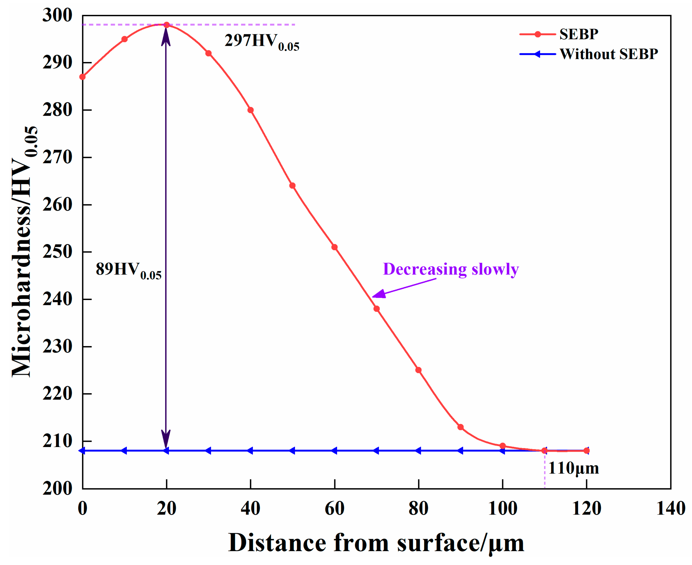
Figure 9.
Surface view of 22CrMoH steel after SEBP.

Figure 10.
Comparison of microphase organization of GC specimens with and without SEBP: (a) Metallographic structure, (b) heart structure, (c) carburized layer.
Figure 10.
Comparison of microphase organization of GC specimens with and without SEBP: (a) Metallographic structure, (b) heart structure, (c) carburized layer.

Figure 11.
XRD patterns of GC specimens with and without SEBP.

Figure 12.
Elemental content distribution of EDS scans at different locations: (a) matrix carburization; (b) carburization under SEPB conditions.
Figure 12.
Elemental content distribution of EDS scans at different locations: (a) matrix carburization; (b) carburization under SEPB conditions.
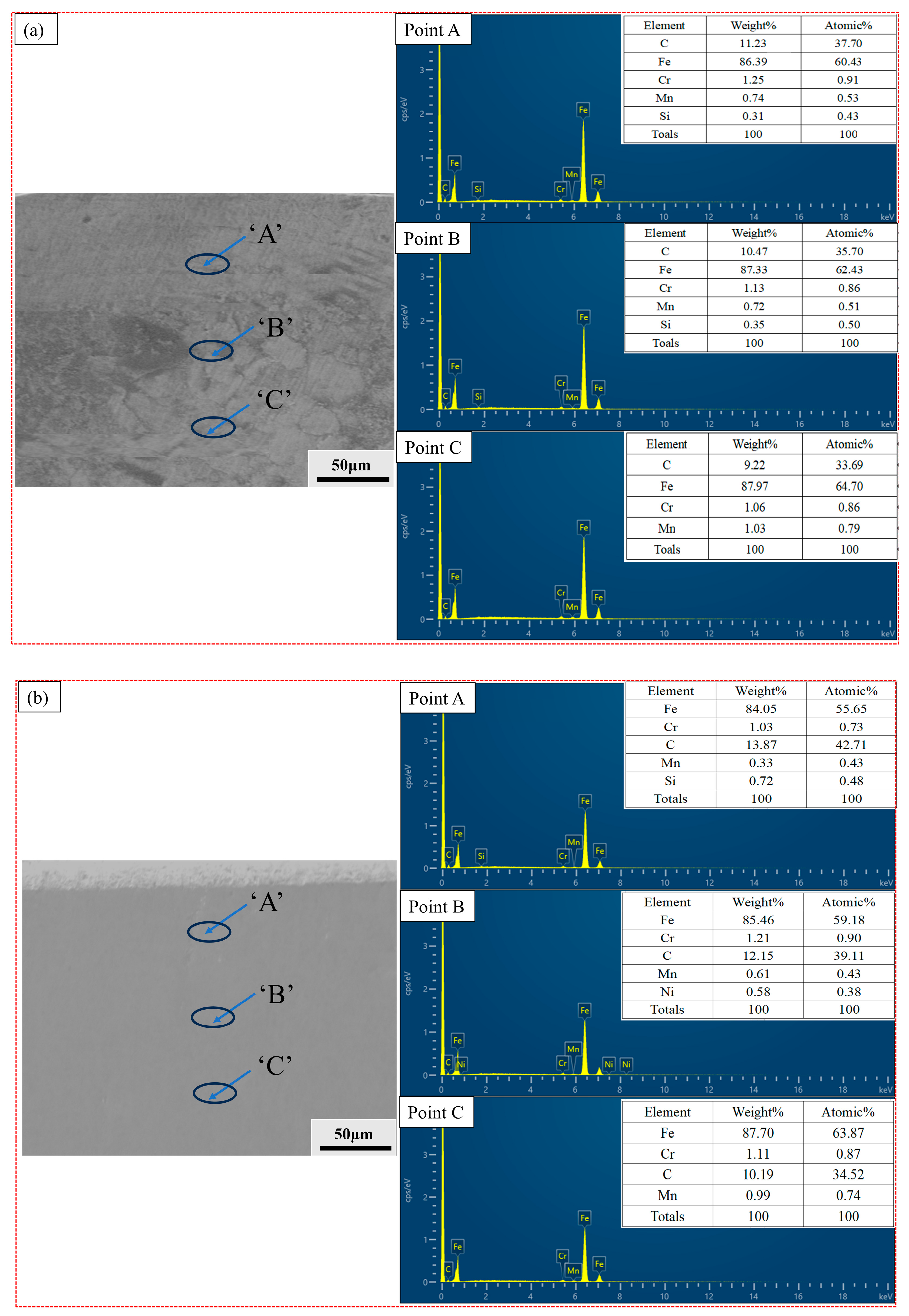
Figure 13.
Cross-sectional microhardness of GC specimens with and without SEBP.

Figure 14.
Friction coefficients of GC specimens with and without SEBP.

Figure 15.
Grain defects in deformed layer: (a) Grain defects under SEBP; (b) grain boundaries of the matrix boundary.
Figure 15.
Grain defects in deformed layer: (a) Grain defects under SEBP; (b) grain boundaries of the matrix boundary.

Table 1.
Chemical composition (mass fraction, %).
| Element | C% | Si% | Mn% | S% | P% | Cr% | Mo% | Ni% | Cu% |
|---|---|---|---|---|---|---|---|---|---|
| Technical requirement | 0.17~0.24 | 0.17~0.34 | 0.40~0.70 | ≤0.035 | ≤0.035 | 0.80~1.10 | 0.15~0.25 | ≤0.3 | ≤0.3 |
| Analysis results | 0.22 | 0.24 | 0.45 | 0.020 | 0.017 | 0.95 | 0.18 | 0.17 | 0.23 |
Table 2.
Toroidal-gas-carburizing process.
| Name | Preoxidation | Heat | Carburization | Diffuse | Heat Preservation | Quenching | Cleanse | Tempering |
|---|---|---|---|---|---|---|---|---|
| Station number | 4 | 6 | 28 | 7 | 1 | 1 | 3 | 9 |
| Temperature (°C) | 450 | 920 ± 10 | 920 ± 10 | 50 ± 10 | 850 ± 10 | 60–90 | 50 | 190 ± 10 |
| Carbon potential (%) | / | / | 1.1 | 0.8 | 0.8 | / | / | / |
| Time (min) | 240 | 360 | 480 | 420 | ≤60 | ≤60 | ≤180 | 240 |
| Gas | Air | N2-CH4O | N2,CH4O, Natural gas | N2 | Protective gas | Air | Air | |
Table 3.
Simulation parameters.
| Current (mA) | Speed (mm/min) | Radius (mm) |
|---|---|---|
| 3 | 250 | 5 |
| 3 | 300 | 5 |
| 3 | 350 | 5 |
| 4 | 250 | 5 |
| 4 | 300 | 5 |
| 4 | 350 | 5 |
| 5 | 250 | 5 |
| 5 | 300 | 5 |
| 5 | 350 | 5 |
Disclaimer/Publisher’s Note: The statements, opinions and data contained in all publications are solely those of the individual author(s) and contributor(s) and not of MDPI and/or the editor(s). MDPI and/or the editor(s) disclaim responsibility for any injury to people or property resulting from any ideas, methods, instructions or products referred to in the content. |
© 2024 by the authors. Licensee MDPI, Basel, Switzerland. This article is an open access article distributed under the terms and conditions of the Creative Commons Attribution (CC BY) license (https://creativecommons.org/licenses/by/4.0/).
Share and Cite
MDPI and ACS Style
Jiang, W.; Qu, J.-J.; Liu, F.; Yue, G.; Zhou, L.; Luo, Y.-C.; Ning, H.-W. Effect of Scanning Electron Beam Pretreatment on Gas Carburization of 22CrMoH Gear Steel. Coatings 2024, 14, 611. https://doi.org/10.3390/coatings14050611
AMA Style
Jiang W, Qu J-J, Liu F, Yue G, Zhou L, Luo Y-C, Ning H-W. Effect of Scanning Electron Beam Pretreatment on Gas Carburization of 22CrMoH Gear Steel. Coatings. 2024; 14(5):611. https://doi.org/10.3390/coatings14050611
Chicago/Turabian StyleJiang, Wei, Jing-Jing Qu, Fei Liu, Gao Yue, Lei Zhou, Yu-Cheng Luo, and Hui-Wang Ning. 2024. "Effect of Scanning Electron Beam Pretreatment on Gas Carburization of 22CrMoH Gear Steel" Coatings 14, no. 5: 611. https://doi.org/10.3390/coatings14050611
Note that from the first issue of 2016, this journal uses article numbers instead of page numbers. See further details here.