
Mechanism Analysis and Optimization Design of Exoskeleton Robot with Non-Circular Gear–Pentabar Mechanism
by
Guibin Wang
1, 
Maile Zhou
1,*,
Hao Sun
1,
Zhaoxiang Wei
1,
Herui Dong
1,
Tingbo Xu
1 and
Daqing Yin
2 1
School of Agricultural Engineering, Jiangsu University, Zhenjiang 212013, China
2
College of Engineering, Northeast Agricultural University, Harbin 150030, China
*
Author to whom correspondence should be addressed.
Machines 2024, 12(5), 351; https://doi.org/10.3390/machines12050351
Submission received: 18 April 2024
/
Revised: 15 May 2024
/
Accepted: 16 May 2024
/
Published: 19 May 2024
(This article belongs to the Section Robotics, Mechatronics and Intelligent Machines)
Abstract
:To address the complex structure of existing rod mechanism exoskeleton robots and the difficulty in solving the motion trajectory of multi−rod mechanisms, an exoskeleton knee robot with a differential non−circular gear–pentarod mechanism is designed based on non−circular gears with arbitrary transmission ratios to constrain the degrees of freedom of the R-para-rod mechanism. In this study, the kinematic model of a non-circular gear–five−rod mechanism is established based on motion mapping theory by obtaining the normal motion positions of the human lower limb. An optimization design software for the non-circular gear–five−rod mechanism is developed using the MATLAB 2018b visualization platform, with the non−circular active gear as the sole input variable. A set of ideal parameters is obtained through parameter adjustment and optimal parameter selection, and the corresponding trajectories are compared with human trajectories. The three−dimensional model of the mechanism is established according to the obtained parameters, and the motion simulation of the non−circular gear–five−bar mechanism demonstrates that the mechanism can better reproduce the expected human knee joint motion posture, meeting the working requirements of an exoskeleton knee robot.
1. Introduction
Rehabilitation robotics is a high−end rehabilitation medical technology developed in recent years, combining robotics and medical technology to help disabled patients regain motor function. With the development of exoskeleton technology, exoskeletons are widely used in fields such as human assistance and rehabilitation [1,2]. Exoskeleton−assisted robots are mainly divided into two functional applications: load exoskeleton−assisted robots that enhance the load capacity of healthy individuals, and rehabilitation exoskeleton−assisted robots that strengthen the joints of disabled and immobile individuals [3]. Rehabilitation exoskeleton−assisted robots primarily assist patients in restoring the normal movement gait of the lower limbs through being worn by patients.
Correct and scientific rehabilitation training plays a crucial role in the recovery of patients’ motor functions, and human lower limb exoskeleton rehabilitation robots have become the most basic and effective means to help patients reintegrate into society [4,5,6]. Freivogel S et al. designed the Lokohelp rehabilitation robotic device, an electromechanical device placed on a treadmill for use, which can aid the completion of gait training but limits the patient’s upper body movement [7]. The eLEGS rehabilitation robot, developed by the Berkeley Bionics Company in the United States, is motor-driven and designed with four degrees of freedom and a pair of crutches. It features a complex detection and control system that helps patients complete gait training by controlling the relevant actuators [8]. A.C. Etoundi et al. proposed a deformable four−rod−mechanism prosthetic knee joint experimental model that utilizes an anti-parallelogram mechanism to realize the function of the prosthetic knee joint, thereby improving the force stability of the device. The use of a stretchable nylon rope wrapped around the four-rod mechanism provides this prosthetic knee joint with a certain degree of flexibility [9]. J. D’Alessio et al. theoretically designed a prosthetic knee joint based on non−circular gear meshing. This prosthetic knee joint employs the RRSS spatial single−degree−of−freedom four−link mechanism axial surface optimization to obtain the specific parameters of the non−circular gears in principle, better simulating the rotational characteristics of the human knee joint [10]. N. Ghaemi et al. proposed a multi−lever−mechanism prosthetic knee joint based on flexible joints in force analysis and optimization. By replacing a certain rigid hinge in the traditional multi−rod mechanism with a flexible hinge and using force analysis to establish the optimization objective of the flexible joint, they optimized the flexible joint to reduce the control torque of the prosthetic knee joint [11]. Sébastien Briot et al. proposed a method based on a technology−oriented performance criterion that enables the topological optimization of a robot, globally valid in the workspace or in a set of given trajectories, using an optimization algorithm that becomes a linearization method and allowing the robust optimization of robot performance in the workspace [12]. Yilun Sun et al. developed a two−finger gripper based on a continuous structure using a design method based on three−dimensional topological optimization, demonstrating through experimental verification that this three−dimensional topological−optimization−based robot design is feasible and greatly improves design efficiency [13]. Guoqin Gao et al. proposed an improved RANSAC algorithm, which was applied to a three−degree−of−freedom parallel robot developed by them to detect the robot’s attitude, and the results showed that the method improved the accuracy and efficiency of detecting the robot’s attitude [14]; Ji Chen et al. proposed a convex optimization method based on the time−optimal trajectory of the robot with added constraints, which made use of the B−splines, enabling a smooth and time−optimal robot trajectory to be efficiently derived [15]; Ji Chen et al. proposed a convex optimization method based on the added constraints. B−splines, which makes it possible to effectively derive smooth and short time−optimal robot trajectories [15]; Shi Xiaohua et al. designed a multi−joint, sitting/horizontal lower limb rehabilitation robot with a seat that can automatically adjust the backrest angle and two exoskeleton−type mechanical legs, adapting to patients of different heights and body types [16]. Jianfeng Li et al. combined the analysis of human–machine kinematic compatibility, human–machine closed-chain degrees of freedom, and human–machine constraint moment action properties to propose a rehabilitation exoskeleton mechanism configuration compatible with human knee joint kinematics. They designed a knee rehabilitation exoskeleton mechanism that can adapt to the motion characteristics of the human knee joint rotation axis [17]. Ma Chunsheng et al. proposed a mixed−link exoskeleton knee joint, a lower limb exoskeleton knee joint that uses a 3−RRR (R denotes rotating vice) mixed-link mechanism to solve the problem of human and machine knee joint axis overlap [18]. Yu Chennan et al. designed a non−circular gear–five−bar exoskeleton knee rehabilitation device based on four task postures, which is a five−bar mechanism combining a 2R open chain, a 3R open chain, and a pair of non−circular gears, to satisfy the trajectory and posture requirements of the knee joint [19]. Li Shuang et al. proposed a lower limb rehabilitation robot based on a parallel mechanism, which uses two sets of 3−PRPR parallel mechanisms as rehabilitation actuators corresponding to the right and left lower limbs of the human body, offering three translational degrees of freedom and a simple and flexible structure [20].
The knee joint trajectory in anthropomorphic gait is inherently complex. Traditional linkage mechanisms used to control anthropomorphic gait trajectories suffer from disadvantages such as complex structures and a tendency toward vibration. Conversely, gear transmissions offer the advantages of stability and compact structure [21]. Non−circular gears, in particular, facilitate the achievement of more complex motion trajectories. Accordingly, this paper presents the design of an exoskeleton knee rehabilitation device incorporating a non−circular gear and a five−bar mechanism. This combination results in a device with a simplified structure and smooth movement, significantly reducing manufacturing difficulties. The device offers body protection and movement assistance, adapts well to various patient body types, and corrects abnormal gaits by replicating normal human gait clinical applications, the device can be adjusted according to the patient’s body type, and the power setting can be tailored to enable the patient to gradually recover knee function following the normal patterns. This promotes the normalization of motor sensations and accelerates the recovery of knee joint neural functions using the gait trajectory provided by the mechanism. This ultimately assists patients in returning to the normal functional state of the knee joint. The design of this rehabilitation device contributes positively to patient recovery, the advancement of rehabilitation medical care in China, and overall innovation and development in the healthcare sector.
2. Non-Circular Gear–Constrained Five-Bar Mechanism
Function Mapping of the End Trajectory of the Non-Circular Gear Mechanism
Currently, prosthetic knee joint designs based on the natural movement position of human limbs include four−bar−mechanism prosthetic knee joints. For example, Jianan Lu et al. from the University of Hong Kong designed a prosthetic knee joint based on a flexible four−bar mechanism in the theoretical stage [22]. Yu Hongying et al. proposed the “marking line rotation method” and “conversion rack method” for the approximation and synthesis of multi-positional rigid−body guides of different four-bar mechanism types [23]. Xiyao Wu et al. proposed a four-bar mechanism prosthetic knee joint model based on the optimization of the instantaneous centerline trajectory of the human knee joint [24]. Bo Wu et al. proposed a prosthetic limb based on an incomplete gear−linkage structure of the knee joint [25]. However, traditional linkage mechanisms have limitations in their feasible solution domains, and it is difficult to solve the trajectory synthesis problem with more than four poses for multi−bar mechanisms, often requiring more bars for multi−position synthesis.
Humanoid motion positions are complex and require high accuracy, which traditional rigid−body mechanisms struggle to meet. Therefore, this study designs a single−stage non−circular gear−five−bar mechanism based on an arbitrary ratio of non−circular gears on the five−bar mechanism, as shown in Figure 1. The mechanism consists of a single−stage non−circular gear system and a five−bar mechanism. The three non−circular gears are Bessel gears, and the shape of the non−circular center gear knuckle curve is controlled by 12 Bessel type−value points. The non−circular gear system has 22 mechanism parameters, including 11 type-value point pole diameters and 11 type−value point pole angles. The five−bar mechanism contains six configuration parameters: links L1, L2, L3, L4, L5, and L6. There are also three initial position angle parameters: the initial installation angle of the non−circular wheel system and the initial installation angles of links L1 and L2 with respect to the frame (non−circular wheel system). In total, 31 parameters determine the configuration of the non−circular gear–five−bar mechanism. As a result, the feasible solution domain of the non−circular gear−five−bar mechanism is large, and any transmission speed ratio can be realized, which is conducive to solving complex position synthesis problems. The basic configuration of a lower limb rehabilitation robot based on the non−circular gear−five−bar mechanism can greatly reduce the difficulty of the control strategy and the coupling of the power input.
3. Establishment of the Mechanism’s Kinematics Model
The kinematics model of the non−circular gear−five−bar mechanism is shown in Figure 2. A right-angled coordinate system is established with the rotation center O of the non−circular center wheel as the origin. The left and right conjugate non−circular gear rotation centers are O1 and O2, respectively, and the center distance is |O1O2|. The non−circular center gear is the main wheel, with an angular velocity of ω, and the non−circular center wheel rotation angle is expressed as:
The right-side conjugate non-circular gear rotation angle is expressed as:
where is the ratio between the non-circular center wheel and the non-circular conjugate gear. The left conjugate non-circular gear angle is expressed as:
The coordinates of the articulated points A’ and C’ are expressed as:
where is the initial mounting angle of the frame, is the initial mounting angle of the rod , is the initial mounting angle of the rod , and the coordinates of the articulation point B’ are:
A system of equations is created from equation (6) as follows:
Solving yields the equations for the and turning angles of the connecting rod:
Among them:
The equation of motion for point P at the end can be established from the rods , , :
Among them:
4. Obtaining the Human Knee Joint Movement Position
The human knee joint, consisting of the lower end of the femur, the upper end of the tibia, and the patella, is the largest and most complex joint in the human body. It is a synovial joint capable of flexion and extension in the sagittal plane and axial rotation when flexed. A well−designed knee joint structure can effectively improve the mechanical properties of the lower limb exoskeleton, enabling the development of diverse movement patterns for human lower limb gait.
The precise position was obtained by photographing multiple states of the human lower limb gait. First, two white marked dots, 15 cm apart, were attached to the subject’s left leg, with the knee joint as point A and the dot on the calf as point B (Figure 3). Throughout the experiment, the human upper body remained upright, and the position of the lower body was unchanged. The leg was lifted to simulate the gait of walking, cycling through several groups, thus obtaining the human knee joint movement posture during the cycle, as shown in Figure 4.
The captured images were analyzed, and the knee joint trajectory was represented by the trajectory of marking point A during one movement cycle. The line connecting marking points A and B was considered as the rod representing the calf, and the instantaneous positional attitude of the calf was derived through the line AB. The positional attitude of the calf was extracted from four key points, which were fitted to the knee joint’s movement trajectory. The four key points in the trajectory were marked to show the calf’s attitude at each moment, as shown in Figure 5.
5. Development of Optimization Design Software and Parameter Optimization
5.1. Development of Optimization Design Software
Under the natural state of human knee joint movement, which involves complex planar motion, using a rigid-body mechanism to simulate the knee joint movement requires not only the displacement of the knee joint but also the change in its attitude to be considered. The traditional mechanism-mapping method is almost unable to obtain the motion position of the knee joint, and the rod mechanism analytical method for complex multi-positions often has a small feasible solution domain or cannot be solved at all. In this study, based on the MATLAB 2018b visualization platform and the kinematic model of the non−circular gear−five−bar mechanism, optimization design software for the non−circular gear−five-bar mechanism was developed with the non-circular active gear as the only input variable, as shown in Figure 6. The main interface of the optimization design software includes four parts: ① the graphic display area; ② parameter control area; ③ kinematic performance display area; and ④ menu bar. The software can calculate the end trajectory and motion attitude of the mechanism in real time according to different mechanism parameters and can intuitively display the motion simulation of the mechanism under the current parameters. Moreover, in the case of lower limb damage, the displacement speed of the lower limbs during assisted recovery must not be too large, and the inertia force must not be excessive. The kinematic performance display area can display the displacement speed and acceleration curve of the mechanism’s end under the current parameters in real time, allowing designers to adjust the parameters to obtain the ideal kinematic characteristics of the mechanism. The development of optimization software for this non−circular gear–five−bar mechanism can greatly reduce the difficulty of mechanism design and shorten the design cycle.
5.2. Parameter Optimization
The motion process of lower limb rehabilitation robots is a complex planar motion with high requirements in terms of the trajectory and attitude of the non−circular gear–five−bar mechanism. Parameter optimization has strong coupling, making it a multi−objective, multi−parameter, and non−linear optimization problem. It is necessary to analyze the influence of mechanism parameters on trajectory and attitude and then complete the parameter optimization of the non−circular gear−five−bar mechanism to guide the improvement of the exoskeleton robot design. In this study, based on the work requirements of the key stages of upright, knee lift, and swing during the rehabilitation operation and the motion characteristics of the rehabilitation mechanism, the influence of different rod length parameters on the trajectory was analyzed, as shown in Figure 7.
In this study, a series of optimization objectives were proposed based on the work requirements of the key phases of the rehabilitation process, such as upright, knee lifting, and swinging, and the motion characteristics of the human leg. First, the knee joint motion trajectory was extracted based on video shooting as the benchmark trajectory. Second, based on the non−circular gear−five−bar mechanism optimization design software, a parameter-guided heuristic algorithm and human−computer interaction optimization method were used to optimize the L1–L6 rod lengths [26], the non−circular gear control point parameters, and the mechanism mounting angle. The motion trajectory of the non-circular gear−five−bar mechanism was compared with the benchmark trajectory until the optimal trajectory position and the corresponding mechanism parameters that satisfied a series of optimization objectives were obtained. The “parameter−guided” heuristic optimization algorithm first quantizes the parameters and target values, inputs the initial values, and calculates the equivalent target values, and for the worst target, changes the equivalent parameters in forward and backward steps each time. It then compares the equivalent parameters that are closest to the equivalent target values and finally calculates the initial values to determine whether each objective value is above the qualified level. After using the parameter-guided heuristic optimization algorithm to obtain the qualified transplanting trajectory, the human−computer interaction fine-tuning optimization method is used to further optimize the parameters. This method is based on the optimization software of the developed non−circular gear−five−bar mechanism, which corresponds to the parameter adjustment and control area of the mechanism. Each parameter corresponds to fine−tuning buttons, allowing optimization to be carried out by pressing the buttons, observing the changes in the trajectory, and determining whether each target value is above the qualified level. The optimization is carried out by simply pressing the fine−tuning buttons, observing the changes in the trajectory, and adjusting to obtain a relatively good trajectory. The optimal trajectory parameters finally obtained are as follows:
r0 = 64, r1 = 87, r2 = 55, r3 = 70, r4 = 89, r5 = 140, r6 = 181, r7 = 137, r8 = 110, r9 = 72, r10 = 83, θ1 = 60°,
θ2 = 67°, θ3 = 104°, θ4 = 175°, θ5 = 151°, θ6 = 196°, θ7 = 240°, θ8 = 274°,
θ9 = 282°, θ10 = 300°, φH0 = 0°, L1 = 136 mm, L2 = 277 mm, L3 = 316 mm, L4 = 80 mm,
L5 = 164 mm, L6 = 174 mm, α1 = 178°, α2 = 36°.
According to the above preferred parameters, a posture can be obtained, as shown in Figure 8b. Compared with the actual knee joint movement posture shown in Figure 8a, it can be seen that the posture obtained by the selected parameters can satisfy the requirements of human lower limb rehabilitation movement in its natural state.
6. Kinematic Simulation
6.1. Establishment of Virtual Prototype
After parameter adjustment and selection of an optimal set of parameters, a three-dimensional model sketch of the non−circular gear–five−bar mechanism was established based on the resulting data. Non−circular gears utilize the developed 3D software for non−circular internal gears to input the parameters of the non−circular gears and thus generate a non−circular gear model [27]. The components were then assembled according to the derived mounting angles, resulting in the three−dimensional model shown in Figure 9. The working sketch of the mechanism is presented in Figure 10. The mechanism is mounted on a pedestal, which is fitted with leggings for the knee joint area. The patient wears the mechanism using the leggings, enabling them to carry out the desired gait training with the assistance of the mechanism, aiding in their recovery. The non−circular wheel system comprises a sun wheel and two planetary wheels. The sun wheel serves as the active wheel, driving the rotation of the two planetary wheels, which in turn drive the movement of the rod mechanism. Rod 1 is fixed to planetary wheel I, while rod 3 is fixed to planetary wheel II. As the two planetary wheels rotate, the actuator reproduces the desired human knee joint movement posture through the transmission of the rod mechanism. The device is attached to the work frame by a rod mechanism, which includes slides that can be adjusted to accommodate patients of different heights and leg lengths.
6.2. Simulation
The established 3D model was imported into ADAMS, and motion constraints, force, and drive were added to the non-circular gear–five−bar mechanism. A virtual simulation was then performed, as shown in Figure 11. The simulation results demonstrate that the non−circular gear–five−bar mechanism meets the design requirements and can reproduce the trajectory of normal human knee joint movement. The correctness of the theoretical analysis and virtual simulation was verified by comparing the trajectory of the actual human knee joint, the trajectory corresponding to the parameters from the optimization software, and the trajectory obtained by the virtual motion simulation.
Post−processing of the virtual simulation results yields the velocity curve of the mechanism during the working time. Figure 12 shows the velocity curve of the mechanism in the X and Y directions obtained through simulation, while Figure 13 presents the theoretical velocity curve of the mechanism in the X and Y directions from the optimization design software. Comparing the simulated velocity curve with the velocity curve from the optimization design software, both represent the velocity curve of the mechanism working for one cycle, and the trends of the two velocity curves are essentially the same.
7. Conclusions
- (1)
- Aiming to address the complexity of existing rod mechanism exoskeleton knee robots and leveraging the advantages of gear mechanisms, such as stable transmission and simple structure, an exoskeleton knee robot with a non−circular gear–pentarod mechanism is proposed. The kinematic model of the non−circular gear–pentarod mechanism is established based on theoretical analysis.
- (2)
- The motion posture of the human knee joint is obtained through testing. Based on the MATLAB visualization platform, optimization design software is developed by adopting the rigid-body guide heuristic algorithm and the kinematic model of the non−circular gear−five rod mechanism. The motion trajectory of the human knee joint is set as the target trajectory, enabling the selection of an ideal set of parameters through optimization adjustment.
- (3)
- Trajectories corresponding to different rod lengths are obtained by adjusting various rod lengths. The response law of rod length parameters to the end trajectory of the actuator is derived through comparative analysis, further guiding the improved design of the exoskeleton knee robot.
- (4)
- According to the parameters obtained from adjustment and optimization, a three−dimensional model of the non−circular gear−five rod mechanism is established and imported into ADAMS for kinematic simulation. The trajectory obtained from virtual simulation, the trajectory obtained from the optimization design software, and the trajectory of the human knee joint are compared for validation. The results demonstrate that the non−circular gear−five rod mechanism complies with the design requirements and can meet the working requirements of the exoskeleton knee robot. This study did not involve physical processing or experiments in any way. The next step will be to continue processing the device and conducting tests. If problems are found during the experiments, they will be corrected in a timely manner. Additionally, a lightweight design will be pursued to reduce the weight of the device, making it more comfortable for patients to wear the equipment.
Author Contributions
M.Z. provided project management and financial support; G.W. established the kinematic model, developed the software, participated in the 3D model construction, and wrote articles; H.S. performed the experiment simulating the normal posture of the human body and carried out kinematic simulation; Z.W. carried out parameter optimization and trajectory extraction; H.D. and T.X. drew the 3D model of the mechanism; and D.Y. guided the study. All authors have read and agreed to the published version of the manuscript.
Funding
This study was financially supported by the Key R&D Plan of Zhenjiang City—Modern Agriculture (Grant No. NY2023003), Jiangsu Agriculture Science and Technology Innovation Fund (Grant No. CX(22)3089), China Postdoctoral Science Foundation (Grant No. 2021M691315), National Natural Science Foundation of China (Grant No. 52005221), Natural Science Foundation of Jiangsu Province (Grant No. BK20200897), Key Laboratory of Modern Agricultural Equipment and Technology (Jiangsu University), High-Tech Key Laboratory of Agricultural Equipment and Intelligence of Jiangsu Province, and# Priority Academic Program Development of Jiangsu Higher Education Institutions (Grant No. PAPD-2018-87), Key Laboratory of Modern Agricultural Equipment and Technology (Jiangsu University), Ministry of Education.
Data Availability Statement
Data is contained within the article.
Acknowledgments
The authors would like to thank Jiangsu Provincial Key Laboratory of Agricultural Equipment and Intelligent High-tech Research.
Conflicts of Interest
The authors declare no conflicts of interest.
References
- Song, Z.B.; Ma, T.Y.; Nie, C.; Niu, Y.J. A new skeleton model and the motion rhythm analysis for human shoulder complex oriented to rehabilitation robotics. Appl. Bionics Biomech. 2018, 2018, 2719631. [Google Scholar]
- Hunt, J.; Lee, H. A new parallel actuated architecture for exoskeleton applications involving multiple degree-of-freedom biological joints. J. Mech. Robot. Trans. ASME 2018, 10, 051017. [Google Scholar] [CrossRef]
- Song, Q.Z.; Wang, X.G.; Wang, X.; Wang, Y. Development of multijoint exoskeleton-assisted robot and its key technology analysis: An overview. Acta Armamentarii 2016, 37, 172–185. (In Chinese) [Google Scholar]
- Martinez-Velilla, N.; Cadore, E.L.; Casas-herrero, A.; Idoate-Saralegui, F. Physical activity and early rehabilitation in hospitalized elderly medical patients: Systematic review of randomized clinical trials. J. Nutr. Health Aging 2016, 20, 738–751. [Google Scholar] [CrossRef] [PubMed]
- Clark, D.J. Automaticity of walking: Functional significance, mechanism, measurement and rehabilitation strategies. Front. Hum. Neurosci. 2015, 9, 246–254. [Google Scholar] [CrossRef] [PubMed]
- Gao, C.Y.; Liu, F.; Jiang, H.B. Preliminary Study on Current Research Status and Clinical Application of Lower Limb Rehabilitation Robot Mechanisms. Chin. J. Med. Instrum. 2024, 48, 30–37. [Google Scholar]
- Freivogel, S.; Schmalohr, D.; Mehrholz, J. Improved walking ability and reduced therapeutic stress with an electromechanical gait device. J. Rehabil. Med. 2009, 41, 734–739. [Google Scholar] [CrossRef] [PubMed]
- Naditz, A. Medical connectivity-new frontiers: Telehealth innovations of 2010. Telemed. E Health 2010, 6, 986–992. [Google Scholar]
- Etoundi, A.; Lock, R.; Vaidyanathan, R.; Burgess, S.C. A Bio-Inspired Condylar Knee Joint for Knee Prosthetics. Int. J. Des. Nat. Ecodynamics 2013, 8, 213–225. [Google Scholar] [CrossRef]
- D’Alessio, J.; Russell, K.; Lee, W.-T.; Sodhi, R.S. On the Application of RRSS Motion Generation and RRSS Axode Generation for the Design of a Concept Prosthetic Knee. Mech. Based Des. Struct. Mach. 2017, 45, 406–414. [Google Scholar] [CrossRef]
- Ghaemi, N.; Zohoor, H.; Ghaemi, H. Dynamic performance of different knee mechanisms with compliant joints. Sci. Iran. Trans. B Mech. Eng. 2016, 23, 1055–1063. [Google Scholar]
- Briot, S.; Goldsztejn, A. Topology optimization of industrial robots: Application to a five-bar mechanism. Mech. Mach. Theory 2017, 120, 30–56. [Google Scholar] [CrossRef]
- Sun, Y.L.; Liu, Y.Q.; Pancheri, F.; Lueth, T.C. LARG: A Lightweight Robotic Gripper With 3-D Topology Optimized Adaptive Fingers. IEEE ASME Trans. Mechatron. 2022, 27, 2026–2034. [Google Scholar] [CrossRef]
- Gao, G.Q.; Zhang, Q.; Zhang, S. Pose detection of parallel robot based on improved RANSAC algorithm. Meas. Contral. 2019, 52, 855–868. [Google Scholar] [CrossRef]
- Ji, C.; Zhang, Z.Q.; Cheng, G.G.; Kong, M.X.; Li, R.F. A Convex Optimization Method to Time-Optimal Trajectory Planning With Jerk Constraint for Industrial Robotic Manipulators. IEEE Trans. Autom. Sci. Eng. 2023, 1–18. [Google Scholar] [CrossRef]
- Zhou, M.L.; Yang, Y.C.; Wei, M.X.; Yin, D.Q. Method for generating non-circular gear with addendum modification and its application in transplanting mechanism. Int. J. Agric. Biol. Eng. 2020, 13, 68–75. [Google Scholar] [CrossRef]
- Shi, X.H.; Wang, H.B.; Sun, L.; Gao, F.; Xu, Z. Design and Dynamic Analysis of an Exoskeletal Lower Limbs Rehabilitation Robot. J. Mech. Eng. 2014, 50, 41–48. [Google Scholar] [CrossRef]
- Li, J.F.; Huang, X.Q.; Tao, C.J.; Wang, S.; Ji, R. Configuration synthesis and structure design of kneerehabilitation exoskeleton. J. Harbin Eng. Univ. 2017, 38, 625–632. [Google Scholar]
- Ma, C.S.; Yin, X.Q.; Ma, Z.D.; Mi, W.B. Axis Self-adaptive Design and Dimensional Synthesis of Knee Joint of Lower Limb Exoskeleton. Acta Armamentarii 2022, 43, 653–660. [Google Scholar]
- Yu, C.N.; Yao, K.; Zong, Y.Y.; Ye, J.; Chen, J.N. Rigid-Body Guidance Synthesis of Noncircular Gear-Five-BarMechanisms and Its Application in a Knee Joint Rehabilitation Device. Machine 2022, 10, 1110. [Google Scholar] [CrossRef]
- Li, S.; Li, Y.W.; Zhao, M.X.; Chen, Z.M.; Zhu, W.G. Synthesis and Analysis of a Lower-extremity Rehabilitation in Parallel. J. Mech. Eng. 2022, 58, 55–64. [Google Scholar]
- Lu, J.A.; Chen, Y.H. Topology optimisation and customisation of a prosthetic knee joint design. Int. J. Comput. Integr. Manuf. 2013, 26, 968–976. [Google Scholar] [CrossRef]
- Yu, H.Y.; Wang, Z.X.; Li, J.S. A study on the synthesis of rigid-body guiding mechanism method. J. Mach. Des. 2001, 12, 14–17. [Google Scholar]
- Wu, X.Y.; Zhai, S.J.; Hao, Q. Analysis and simulation of prosthetic knee joint four bar mechanism. J. Mach. Des. 2011, 28, 42–45. [Google Scholar]
- Wu, B.; Chen, Z.B.; Chen, M. Design and Simulation of a New Prosthetic Knee Joint. Mach. Des. Manuf. 2015, 6, 5–8. [Google Scholar]
- Zhou, M.L.; Wei, Z.X.; Wang, Z.L.; Sun, H.; Wang, G.B.; Yin, J.J. Design and Experimental Investigation of a Transplanting Mechanism for Super Rice Pot Seedlings. Agriculture 2023, 13, 1920. [Google Scholar] [CrossRef]
- Zhou, M.L.; Yang, J.J.; Xu, T.B.; Ying, J.J.; Wang, X.Z. Optimal design of transplanting mechanism with differential internal engagement non-circular gear trains. J. Agric. Eng. 2022, 53, 1412. [Google Scholar] [CrossRef]
Figure 1.
Non−circular gear–pentabar mechanism exoskeleton robot. (1. Sun wheel; 2. planetary wheel I; 3. rod mechanism; 4. actuator endpoints; 5. motion trajectory; 6. actuator; 7. planetary wheel II).
Figure 1.
Non−circular gear–pentabar mechanism exoskeleton robot. (1. Sun wheel; 2. planetary wheel I; 3. rod mechanism; 4. actuator endpoints; 5. motion trajectory; 6. actuator; 7. planetary wheel II).

Figure 2.
Kinematic analysis.

Figure 3.
Acquisition of knee motion position.
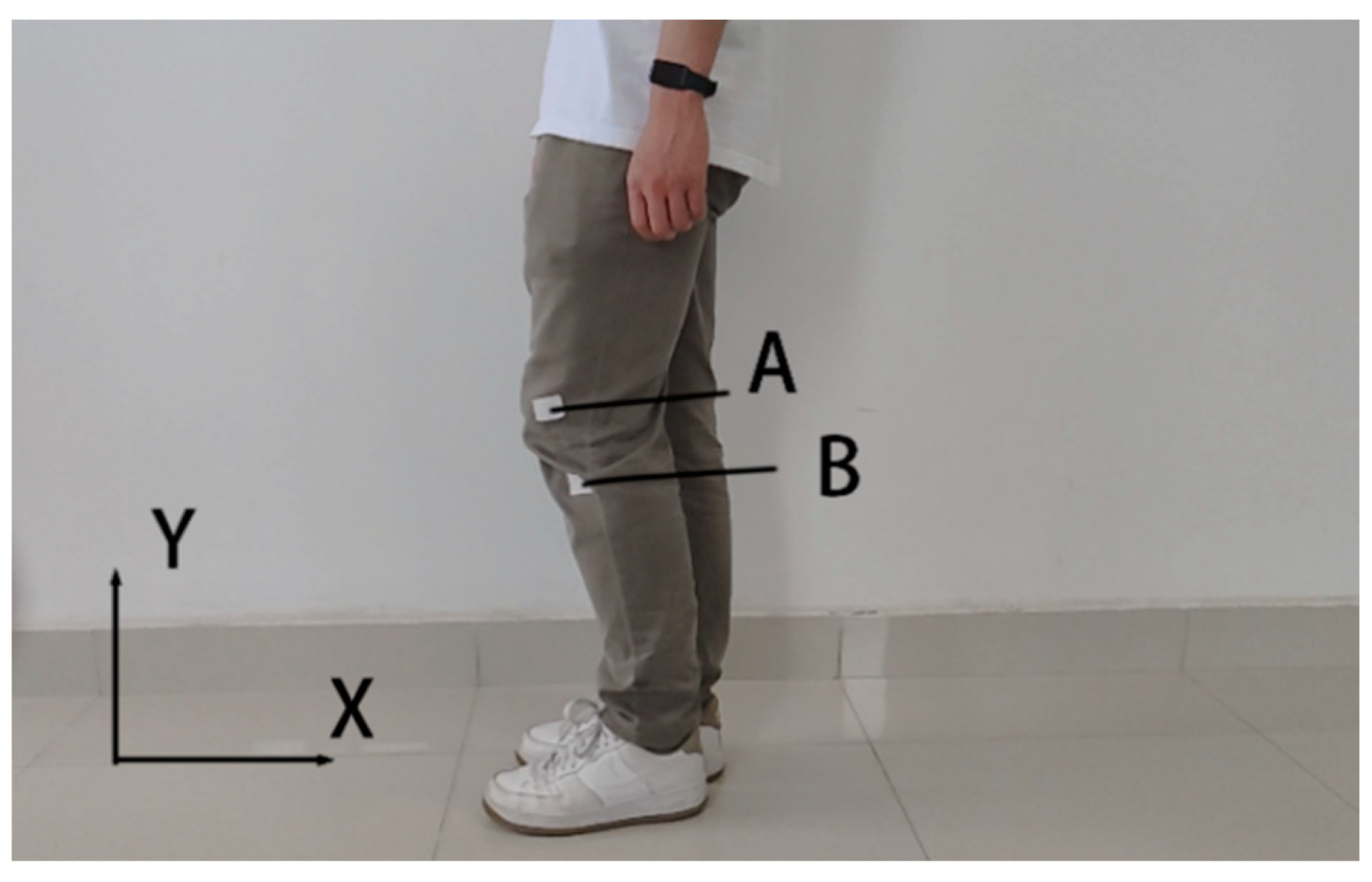
Figure 4.
Human lower limb movement gait.(Figures (a–h) are eight representative images captured in a high−speed camera shooting video during a motion cycle).
Figure 4.
Human lower limb movement gait.(Figures (a–h) are eight representative images captured in a high−speed camera shooting video during a motion cycle).

Figure 5.
Trajectory and position of knee joint movement.
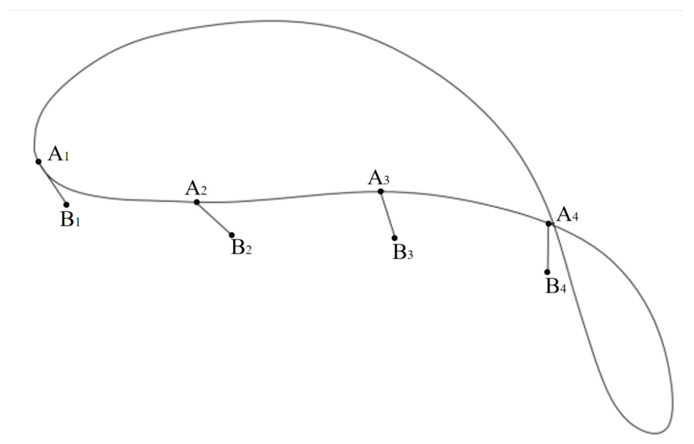
Figure 6.
Optimized design software for the non–circular gear–five bar mechanism.

Figure 7.
Effect of rod length variation on trajectory. (a) Trajectory plots of poles L1 of different lengths; (b) Trajectory plots of poles L2 of different lengths; (c) Trajectory plots of poles L1 of different lengths; (d) Trajectory plots of poles L1 of different lengths; (e) Trajectory plots of poles L1 of different lengths; (f) Trajectory plots of poles L1 of different lengths.

Figure 8.
Comparison of postures. (a) Actual knee movement position; (b) mechanism position of the preferred parameters.
Figure 8.
Comparison of postures. (a) Actual knee movement position; (b) mechanism position of the preferred parameters.
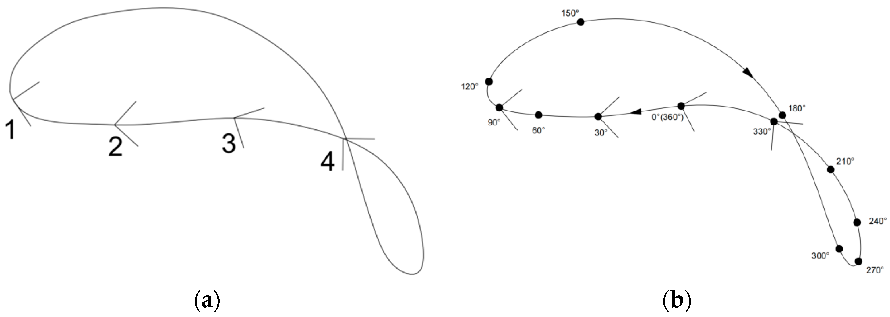
Figure 9.
Sketch of the three−dimensional model of the non−circular gear–five−bar mechanism. (1. Sun wheel; 2. planetary wheel I; 3. rod 1; 4. rod 2; 5. actuator; 6. rod 3; 7. planetary wheel II).
Figure 9.
Sketch of the three−dimensional model of the non−circular gear–five−bar mechanism. (1. Sun wheel; 2. planetary wheel I; 3. rod 1; 4. rod 2; 5. actuator; 6. rod 3; 7. planetary wheel II).
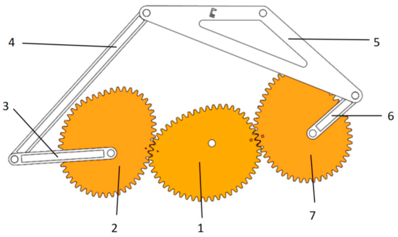
Figure 10.
Working sketch of the virtual prototype.

Figure 11.
Virtual simulation.

Figure 12.
Velocity profile of mechanism simulation. (a) Mechanism X−direction velocity profile; (b) mechanism Y−direction velocity profile.
Figure 12.
Velocity profile of mechanism simulation. (a) Mechanism X−direction velocity profile; (b) mechanism Y−direction velocity profile.

Figure 13.
Theoretical velocity profile of the mechanism. (a) Mechanism X−direction velocity profile; (b) mechanism Y−direction velocity profile.
Figure 13.
Theoretical velocity profile of the mechanism. (a) Mechanism X−direction velocity profile; (b) mechanism Y−direction velocity profile.

Disclaimer/Publisher’s Note: The statements, opinions and data contained in all publications are solely those of the individual author(s) and contributor(s) and not of MDPI and/or the editor(s). MDPI and/or the editor(s) disclaim responsibility for any injury to people or property resulting from any ideas, methods, instructions or products referred to in the content. |
© 2024 by the authors. Licensee MDPI, Basel, Switzerland. This article is an open access article distributed under the terms and conditions of the Creative Commons Attribution (CC BY) license (https://creativecommons.org/licenses/by/4.0/).
Share and Cite
MDPI and ACS Style
Wang, G.; Zhou, M.; Sun, H.; Wei, Z.; Dong, H.; Xu, T.; Yin, D. Mechanism Analysis and Optimization Design of Exoskeleton Robot with Non-Circular Gear–Pentabar Mechanism. Machines 2024, 12, 351. https://doi.org/10.3390/machines12050351
AMA Style
Wang G, Zhou M, Sun H, Wei Z, Dong H, Xu T, Yin D. Mechanism Analysis and Optimization Design of Exoskeleton Robot with Non-Circular Gear–Pentabar Mechanism. Machines. 2024; 12(5):351. https://doi.org/10.3390/machines12050351
Chicago/Turabian StyleWang, Guibin, Maile Zhou, Hao Sun, Zhaoxiang Wei, Herui Dong, Tingbo Xu, and Daqing Yin. 2024. "Mechanism Analysis and Optimization Design of Exoskeleton Robot with Non-Circular Gear–Pentabar Mechanism" Machines 12, no. 5: 351. https://doi.org/10.3390/machines12050351
Note that from the first issue of 2016, this journal uses article numbers instead of page numbers. See further details here.