
In Situ Carbon-Confined MoSe2 Catalyst with Heterojunction for Highly Selective CO2 Hydrogenation to Methanol
National Center for International Research on Catalytic Technology, School of Chemistry and Material Sciences, Heilongjiang University, Harbin 150080, China
*
Authors to whom correspondence should be addressed.
Molecules 2024, 29(10), 2186; https://doi.org/10.3390/molecules29102186
Submission received: 11 April 2024
/
Revised: 29 April 2024
/
Accepted: 4 May 2024
/
Published: 8 May 2024
Abstract
:The synthesis of methanol from CO2 hydrogenation is an effective measure to deal with global climate change and an important route for the chemical fixation of CO2. In this work, carbon-confined MoSe2 (MoSe2@C) catalysts were prepared by in situ pyrolysis using glucose as a carbon source. The physico-chemical properties and catalytic performance of CO2 hydrogenation to yield methanol were compared with MoSe2 and MoSe2/C. The results of the structure characterization showed MoSe2 displayed few layers and a small particle size. Owing to the synergistic effect of the Mo2C-MoSe2 heterojunction and in situ carbon doping, MoSe2@C with a suitable C/Mo mole ratio in the precursor showed excellent catalytic performance in the synthesis of methanol from CO2 hydrogenation. Under the optimal catalyst MoSe2@C-55, the selectivity of methanol reached 93.7% at a 9.7% conversion of CO2 under optimized reaction conditions, and its catalytic performance was maintained without deactivation during a continuous reaction of 100 h. In situ diffuse infrared Fourier transform spectroscopy studies suggested that formate and CO were the key intermediates in CO2 hydrogenation to methanol.
1. Introduction
A large amount of CO2 is emitted when extravagant fossil fuels (coal, oil and natural gas) are consumed, which causes a series of climate problems [1,2]. In view of the current situation, in order to reduce CO2 emissions, carbon capture and storage (CCS) and carbon capture and utilization (CCU) are currently the most effective means [3]. However, the high cost and energy consumption of desorption, compression and storage of captured CO2 greatly limit the large-scale application of CCS. CCU can achieve efficient CO2 recovery and bring certain economic benefits, and it is considered a promising technology to reduce CO2 emissions. As a raw material, CO2 can be converted to fuel and value-added chemicals [4,5]. On the one hand, it can reduce the pressure of the fossil resource shortage; on the other hand, it can bring huge economic benefits. Therefore, the chemical utilization of CO2 to produce value-added chemicals has become one of the hot topics for using a non-toxic, inexpensive, abundant and renewable source of carbon [6,7,8,9]. Among the CO2 utilization routes, synthesizing methanol has received extensive attention [10,11]. Methanol is water-soluble, non-toxic, harmless and easy to store and transport, and it is known as the simplest ‘alcohol’, so it has become one of the most important platform compounds in the chemical industry [12]. Methanol can be miscible with water and a variety of organic matter, serving as an alternative clean fuel, liquid organic hydrogen carrier and common organic solvent [12,13,14]. It can also be used to produce olefins, aromatic hydrocarbons, alkanes and other bulk chemicals [15,16]. At present, the global production of methanol is 110 million metric tons [17].
For the hydrogenation of CO2 to methanol, the utilization of copper-based catalysts has garnered significant interest. The main active substances of copper-based catalysts in over 60% of related reports are Cu-ZnO composite materials [18]. However, two disadvantages hinder the widespread use of copper-based catalysts. One is that the generation of water in the reaction aggravates the sintering of the active phase, resulting in poor stability of the catalyst, and the other is that the selectivity of methanol is limited due to the reverse water gas reaction [19,20]. Compared with copper-based catalysts, noble metal-based catalysts exhibit excellent stability, anti-sintering and anti-poisoning properties and can be used as an effective alternative to copper-based catalysts. Although noble metal catalysts show a high ability to activate hydrogen and promote hydrogenation, the low selectivity of methanol is yielded due to its weak interaction with CO2 in the reaction process. Meanwhile, its low abundance and high cost also limit its large-scale application in CO2 hydrogenation to methanol. Recently, metal oxide catalysts such as In2O3 and Zn-Zr solid solutions have attracted attention [21]. Due to the formation of oxygen vacancies under reaction conditions of 330 °C and 5 MPa, In2O3 provided 100% methanol selectivity in CO2 hydrogenation, but it could be reduced to In0 metal, which caused the deactivation during the reaction [22]. Under industrial conditions, the ZnO-ZrO2 solid solution catalyst demonstrated the capability to facilitate the hydrogenation of CO2 to methanol [23]. The space–time yield of methanol was as high as 7.75 mol·kg−1·h−1 with an 87.0% selectivity of methanol, and excellent stability was shown in the presence of SO2 and H2S. However, shortcomings are shown in the harsh reaction conditions, poor activity and high energy consumption. Therefore, it is still a challenge to develop highly effective non-precious metal catalysts for CO2 hydrogenation to form methanol under relatively mild conditions.
Because of their large surface area and large amounts of coordination-unsaturated surface atoms, two-dimensional layered Mo-based catalysts have attracted widespread attention [24,25]. Due to its similar electronic structure to the noble metal Pt, molybdenum carbide displays excellent catalytic performance for hydrogenation and has been applied in hydrodeoxygenation [26,27] and hydrodenitrogenation [28]. In 1992, molybdenum carbide was used as a catalyst for the hydrogenation of CO2, resulting in a methanol selectivity of only 17%, with methane and CO being the predominant byproducts [29]. DFT results suggested that enhancing the adsorption of CO2 on the catalyst surface was beneficial for inhibiting the complete decomposition of CO2, thus improving the selectivity of methanol [30]. In our previous work, N,S-doped carbon-confined molybdenum carbide catalysts were synthesized by in situ pyrolysis carbonization [31]. The basic sites generated from N and S in the in situ pyrolysis carbonization increased the adsorption amount of CO2. The selectivity of methanol yielded 90% with a CO2 conversion of 20%. In this catalyst, nano-sized MoS2 was also generated in the pyrolysis process, which was a key factor in its excellent catalytic performance. On the one hand, in the presence of MoS2, CO2 was adsorbed and dissociated at sulfur vacancies; on the other hand, in-plane sulfur vacancies could inhibit the deep hydrogenation of CO2 to methane and promote the formation of methanol at low temperatures. More recently, Deng [32] et al. constructed a surface-rich sulfur-vacancy MoS2 catalyst and applied it for the hydrogenation of CO2 to form methanol, with the methanol selectivity reaching 94.3% with a CO2 conversion of 12.5% at 180 °C. MoSe2, as a two-dimensional layered material, has stronger metallicity and lower Gibbs free energy than molybdenum sulfide [33], which is more conducive to the adsorption and activation of hydrogen molecules [34]. More importantly, the adsorption capacity of CO2 is also better than that of MoS2 [35]. However, MoSe2 is mainly involved in photocatalysis and electrocatalysis for the hydrogenation of CO2, and the main reduction products are methane, carbon monoxide and so on [35]. Qu et al. incorporated K into MoSe2 and constructed a K-Mo-Se active phase for catalytic syngas conversion to ethanol. By regulating the K/Mo ratio, the proportion of ethanol in the total alcohol reached 58.7% under optimal reaction conditions [36]. To our best knowledge, there is no report on the use of MoSe2 as a catalyst in the thermocatalytic hydrogenation of CO2 to produce methanol [37,38]. Therefore, the study of the catalytic behavior of MoSe2 is significant for the development of non-noble metal catalysts for CO2 hydrogenation to methanol.
It is well known that, as a typical two-dimensional material, the active sites of MoSe2 are also mainly located at its edges and defect sites. Therefore, reducing the layer number and particle size of MoSe2 is an effective route to enhance its catalytic performance. Confined MoSe2 in carbon materials can effectively prevent the aggregation of MoSe2 and improve its catalytic performance [39,40,41]. In this work, MoSe2 confined by in situ-formed carbon material (MoSe2@C) was prepared by introducing glucose as a carbon source into the precursors using the pyrolysis method and applied to CO2 hydrogenation to form methanol in a fixed-bed reactor. The influences of the preparation conditions and the C/Mo ratio in the precursors on the catalytic performance of MoSe2@C were investigated, and the reaction conditions were optimized. Under optimal reaction conditions, a high methanol selectivity of 93.7% was reached. MoSe2@C also showed excellent catalytic stability during performance evaluation and could be used for at least 100 h without deactivation.
2. Results and Discussion
2.1. Catalyst Characterization
2.1.1. Structural Characterizations
Firstly, X-ray powder diffraction was employed to detect the crystal structure of the prepared samples, and the results are shown in Figure 1. The characteristic diffraction peaks of the three samples appeared at 2θ = 13.7°, 31.4°, 37.9°, 47.5°, 55.9°, 66.5° and 69.5°, corresponding to the (002), (100), (103), (105), (110), (108) and (203) crystal planes of MoSe2 (PDF 29-0914) [42], and no other diffraction peaks were found. These results indicate that the MoSe2 crystal phase was prepared. In addition, a slight shift of the (002) crystal plane could be observed, which was attributed to thermal-induced phase segregation [43]. Compared with MoSe2, the intensity of the diffraction peaks was weakened, and the half-peak width of the corresponding diffraction peaks increased in the XRD patterns of the MoSe2/C sample, indicating that the introduction of a carbon carrier could improve the dispersion of MoSe2 and inhibit the growth of MoSe2 particles. Additionally, the characteristic diffraction peaks corresponding to the (002) crystal plane of graphite carbon were also found at 2θ = 26°. Compared with the XRD patterns of MoSe2 and MoSe2/C, the diffraction peak intensity of MoSe2@C-55 was the weakest, the half-peak width was the widest, and the characteristic diffraction peak (2θ = 13.7°) corresponding to the (002) crystal plane of MoSe2 almost disappeared. These results suggested that the grain size of MoSe2 was the smallest and the layer number of MoSe2 was the lowest in MoSe2@C-55 compared with MoSe2 and MoSe2/C [44,45]. As a consequence, introducing glucose to the precursor could suppress the growth of MoSe2 through the confinement of the in situ generation of carbon material in the pyrolysis process. When the C/Mo ratio in the precursor was raised from 15 to 75, MoSe2@C-15, MoSe2@C-35 and MoSe2@C-75 were prepared. Their XRD patterns are shown in Figure S1. The intensity of the diffraction peak corresponding to MoSe2 gradually declined with the enhancement of the carbon content in the precursor, which means that the confinement of the in situ carbon material improved with the increase in carbon content, and the growth of MoSe2 particles was repressed, which was beneficial to the dispersion of MoSe2 in the carbon material.
In order to observe the microstructure and morphology, MoSe2/C and MoSe2@C-55 were characterized by TEM and HRTEM (Figure 2). The image in Figure 2a shows that MoSe2 dispersed on the coconut shell carbon, which resulted in the low intensity of the XRD diffraction peak. However, its distribution was not uniform, and agglomeration was observed, which caused MoSe2 to show larger particles and more layers. In Figure 2b (HRTEM), lattice fringes of 0.28 nm can be observed, which is consistent with the interplanar spacing of the (100) of MoSe2 [46,47]. Observing the image of MoSe2@C-55, as shown in Figure 2c, the agglomeration and accumulation of MoSe2 particles were effectively inhibited when glucose was introduced to the precursor. This took place because the carbon materials formed from the in situ pyrolysis of glucose showed an inhibitory effect on the growth of MoSe2 particles, which ensured the high dispersion of MoSe2. As a result of it, more active sites were exposed, and its catalytic performance improved. As can also be seen from the HRTEM image (Figure 2d), a lattice fringe spacing of 0.35 nm was also observed, which belonged to the (004) of MoSe2. In addition, a lattice fringe with a spacing of 0.21 nm was also observed (Figure 2d), which was attributed to the (112) of Mo2C [48], indicating that Mo2C particles were generated during the preparation of MoSe2@C-55. Combined with the fact that the corresponding diffraction peaks of Mo2C were not observed in the XRD pattern, it can be inferred that the content of Mo2C was low and highly dispersed. In addition, the HRTEM images in Figure 2d show that the presence of Mo2C interrupted the continuity of MoSe2, causing more edge sites of MoSe2 to expose more active sites [49]. This phenomenon indicated that a MoSe2-Mo2C heterojunction was generated, which would benefit the synergistic effect of MoSe2 and Mo2C in the catalytic process and improve its catalytic performance [50]. The results in Figure S2a–d show that increasing the content of glucose in the precursor was favorable to improving the dispersion of MoSe2, resulting in a gradual decrease in the particle size and layer number of MoSe2, which coincided with the characterization results of XRD. The content of glucose in the precursor also affected the exposed crystal planes of MoSe2 and Mo2C. Setting the C/Mo ratio in the precursor at 15 and 35, lattice fringes of 0.28 nm and 0.23 nm (Figure S2e,f) could be observed in the HRTEM images, which were attributed to the (100) of MoSe2 and the (121) of Mo2C [46,47]. However, lattice fringes of 0.26 nm and 0.21 nm assigned to the (102) of MoSe2 and the (112) of Mo2C were observed (Figure S2h) when the C/Mo ratio in the precursor rose to 75 [48]. Owing to the different crystal faces that would display different catalytic performance [49], it can be inferred that there will be a large difference in the catalytic performance of CO2 hydrogenation to form methanol.
2.1.2. XPS Analysis of Catalysts
The surface chemical state of the catalyst was further analyzed by XPS. The XPS survey spectra shown in Figure S3 suggest that the surface elements of the samples were Mo, Se, C and O.
The XPS spectra of the Mo 3d of the three samples (Figure 3a and Table S1) showed that characteristic peaks were observed at 229.1–229.3 eV and 232.1–232.3 eV, which were attributed to Mo4+ 3d5/2 and 3d3/2 in MoSe2 [48,50]. In addition, fitting peaks at 228.6 eV and 231.6 eV were also found in the Mo 3d of MoSe2@C-55, which corresponded to Mo2+ 3d5/2 and 3d3/2, indicating that Mo2C was generated during the preparation of MoSe2@C-55 [51,52], suggesting that a strong interaction between the carbon formed by the in situ carbonization of glucose and the Mo atoms was formed. The specific binding energy data in Table S1 show that the binding energy of Mo4+ 3d5/2 and 3d3/2 in MoSe2@C-55 was 0.2 eV lower than that of MoSe2 and MoSe2/C, which was caused by the electron transfer between MoSe2 and Mo2C [53], and a strong interaction was formed. In addition, peaks at binding energies of 232.5–232.7 eV and 235.4–235.7 eV, corresponding to Mo-O, were observed due to the surface oxidation that took place when MoSe2@C-55 and MoSe2/C were exposed to air [47,48,49,50,51,52], but the binding energy of MoSe2@C-55 was lower than that of MoSe2/C, which may be due to the protective effect of in situ-formed carbon on the surface of MoSe2@C-55, resulting in a reduction in the oxidation degree. This result demonstrates once again the robust interaction between carbon and Mo in MoSe2@C-55.
The Se 3d XPS spectra are displayed in Figure 3b, and two peaks at 54.7–54.8 eV and 55.7–55.8 eV (Table S2) were assigned to the Se2- 3d5/2 and 3d3/2 of MoSe2 [42,46]. Moreover, MoSe2/C also showed a characteristic peak at about 59.1 eV, assigned to Se oxide (SeOx) [54]. In addition, as shown in Figure 3c and Table S3, the peaks at 284.8 eV and about 286.1 eV in the C 1s spectrum of all samples indicate the formation of a C-C bond and a C-O bond, respectively [55]. The high-resolution XPS spectra of O 1s are shown in Figure 3d and Table S4. The peaks at 530.4 eV, 531.8 eV and 532.8 eV indicate the formation of lattice oxygen (Olat), deficient oxygen (Odef) and adsorbed oxygen (Oads), respectively [56,57]. The proportion of each oxygen species in all oxygen species is shown in Table S4. The proportion of Odef is the highest in the MoSe2@C-55 catalyst. The oxygen vacancies on the surface improved the dissociation of CO2 and tended to produce the desired methanol [57]. Moreover, only the MoSe2@C-55 sample showed a peak at 282.6 eV, which corresponded to a C-Mo bond [53,54]. The data listed in Figure S5 also show that the binding energy of Mo 3d showed a negative shift with the increase in the C/Mo ratio in the precursor, and the Mo2+/Mo4+ ratio on the surface of the catalyst displayed a positive correlation with the carbon content in the precursor (Table S5), suggesting that a higher carbon content in the precursor was beneficial to generating Mo2C.
2.1.3. Characterization of CO2 Adsorption Capacity
The adsorptive capacity of a catalyst for CO2 is an important factor in its catalytic performance in CO2 hydrogenation. Therefore, CO2-TPD was carried out, and the desorption curves are displayed in Figure 4. According to the characterization results, all the CO2 desorption peaks of the prepared MoSe2, MoSe2/C and MoSe2@C-55 catalysts appeared at low temperatures, which corresponded to the presence of weak basic sites on the catalyst surface [58,59]. Compared with MoSe2 and MoSe2/C, MoSe2@C-55 showed the highest desorption temperature of CO2, which means that the activation degree of CO2 on the surface of MoSe2@C-55 was the highest, which would be beneficial to the hydrogenation of CO2. Because the magnitude of the peak area corresponds to the quantity of activated CO2 present on the catalyst surface, the relative desorbed amount of CO2 was calculated by calculating the area of these peaks, and the results are also inset in Figure 4. Based on the desorption amounts of CO2 from MoSe2@C-55 (the relative value is 100%), the desorption amounts of CO2 from the surface of MoSe2 and MoSe2/C were 45% and 54% (by calculating the area of the CO2 desorption peak). These results suggest that the order of CO2 adsorption amounts on the catalyst surface and the ability to activate CO2 were MoSe2@C-55>MoSe2/C>MoSe2.
2.2. Catalytic Performance in CO2 Hydrogenation to Yield Methanol
In a fixed-bed reactor at 180 °C, 3MPa and a Gas Hourly Space Velocity (GHSV) of 3000 mL·gcat−1·h−1, the catalytic performance of MoSe2, MoSe2/C and MoSe2@C-55 was evaluated for CO2 hydrogenation to yield methanol (Table 1). In the presence of the MoSe2 catalyst, the conversion of CO2 was as low as 2.4%, and only a moderate selectivity (52.5%) of methanol was observed in the hydrogenation process, while CO was yielded with a selectivity of 33.1%. In this process, CO was generated from the reverse water gas shift (RWGS) reaction of CO2 on the surface of MoSe2, which was an important intermediate for synthesizing methanol. However, the insufficient active sites were exposed and could not achieve further efficient CO conversion, resulting in high CO selectivity [60]. At the same time, the CH3O* intermediate generated by CO hydrogenation was more likely to undergo C-O cleavage to generate CH3* and OH* at the active sites, resulting in a high CH4 selectivity (10.2%) [32]. In addition, a small amount of dimethyl ether was generated by further dehydration of methanol, which was due to the weak acidity generated from the oxidation of the surface of MoSe2 [61]. The selectivity of methanol increased to 89.9% at a CO2 conversion of 4.3% over the MoSe2/C catalyst, prepared by using coconut shell carbon as support. This was attributed to an increase in the dispersion of MoSe2 on the support, which was beneficial for exposing more edge sites and surface defects due to the reduction in the particle size and layer number of MoSe2 [32]. The conversion of CO2 increased to 9.7% by employing MoSe2@C-55 as a catalyst prepared by using glucose as a carbon source with a C/Mo ratio of 55, while the selectivity of methanol further increased to 93.7% and the selectivity of CH4 decreased to 6.3%, which can be explained by the following reasons: On the one hand, the in situ-formed carbon gave a strong confinement to MoSe2, resulting in a decreasing layer number, which could expose more surface defects conducive to methanol generation. Moreover, the highest amount of deficient oxygen was detected by XPS, and the oxygen vacancies on the surface improved the dissociation of CO2 and tended to produce the desired methanol [57]. On the other hand, in situ-generated Mo2C interrupted the continuity of MoSe2, and the MoSe2-Mo2C heterojunction was formed, which was beneficial for exposing more active sites and activating H2 (Figure S5). The above factors all led to improved CO2 conversion and selectivity of methanol in CO2 hydrogenation. Moreover, the high desorption capacity and the high CO2 activation ability of MoSe2@C-55 were also important factors for increasing CO2 conversion. Based on the above research results, the catalytic performances of a series of MoSe2@C-x (x = 15, 35 and 75) catalysts with different C/Mo ratios in the precursors were also evaluated (Table 1). It can be seen that the selectivity of methanol gradually increased with the increase in C/Mo ratios. When MoSe2@C-75 was used as the catalyst, the selectivity of methanol reached a maximum of 94.3%. This was due to the fact that the number of layers of MoSe2 was reduced as the carbon content in the precursors increased, which was favorable for the exposure of surface defects and conducive to the formation of methanol. The conversion of CO2 reached its maximum when MoSe2@C-55 was used as the catalyst. This took place because MoSe2@C-55 had a stronger ability to adsorb and activate CO2 (Figure S6), causing an acceleration of CO2 conversion.
Compared with the Cu/In2O3-, CuZnAl- and MoS2-based catalysts in the literature, MoSe2@C-55 showed better selectivity for methanol under low reaction temperatures, as shown in Table S7.
In CO2 hydrogenation, CO2 conversion and methanol selectivity were sensitive to the reaction temperature. Using MoSe2@C-55 as a catalyst, the effect of the reaction temperature was investigated under conditions of 3 MPa and a GHSV of 3000 mL·gcat−1·h−1 (Figure 5a). The results in Figure 5a show that the conversion of CO2 increased from 7.1% to 13.5% as the reaction temperature rose from 160 °C to 240 °C, suggesting that high temperatures are beneficial for CO2 to overcome the limitation of its thermodynamic stability, which accelerated the conversion rate of CO2 [62,63]. Setting the reaction temperature at 180 °C, the selectivity of methanol reached a maximum of 93.7% and gradually decreased as the reaction temperature increased. This took place because the reaction of CO2 hydrogenation to methanol was an exothermic reaction, and a higher temperature was not conducive to the formation of methanol. Since the reverse water gas reaction is an endothermic reaction [60], high temperatures are beneficial to its occurrence. Therefore, CO was not detected as a byproduct when the reaction temperature was not higher than 220 °C. But 1.5% of CO and 33.6% of CH4 were generated by raising the reaction temperature to 240 °C. As shown in Figure 5b, the influence of reaction pressure on the hydrogenation of CO2 was also investigated. The conversion of CO2 and the selectivity of methanol were all preferential to enhancing reaction pressure. When the reaction pressure was 2 MPa, CO2 conversion and methanol selectivity were both at a low level (5.6% and 90.6%, respectively). Moreover, the selectivity of methanol improved from 90.6 to 93.7% by changing the reaction pressure from 2 MPa to 3 MPa. When the reaction pressure was further increased, the selectivity of methanol did not change significantly. Finally, the effects of the space–time rate were also investigated (Figure 5c). With the increase in the space–time rate, the residence time of the feed gas on the surface of MoSe2@C-55 was shortened, resulting in a reduction in the conversion of CO2. When the space velocity was 3000 mL·gcat−1·h−1, the highest methanol selectivity at a moderate CO2 conversion was obtained. Under optimized reaction conditions, the test of the catalytic stability of the MoSe2@C-55 catalyst was performed, and the results are shown in Figure 5d. It indicated that the MoSe2@C-55 catalyst could be used continuously for at least 100 h without reducing catalytic activity and showing excellent catalytic stability. The selectivity of methanol was maintained at about 93.7% at a CO2 conversion of approximately 9.7%.
2.3. Reaction Mechanism
In order to explore the reaction mechanism of the hydrogenation of CO2 to generate methanol over the MoSe2@C-55 catalyst, the possible intermediates on the surface of MoSe2@C-55 were detected by in situ diffuse reflectance infrared Fourier transform spectroscopy (DRIFTS). Firstly, the catalyst was activated at 400 °C for 1 h in a pure H2 atmosphere and then refrigerated to 180 °C. Figure 6 shows the experimental results of the CO2 hydrogenation reaction stage at atmospheric pressure and a reaction temperature of 180 °C.
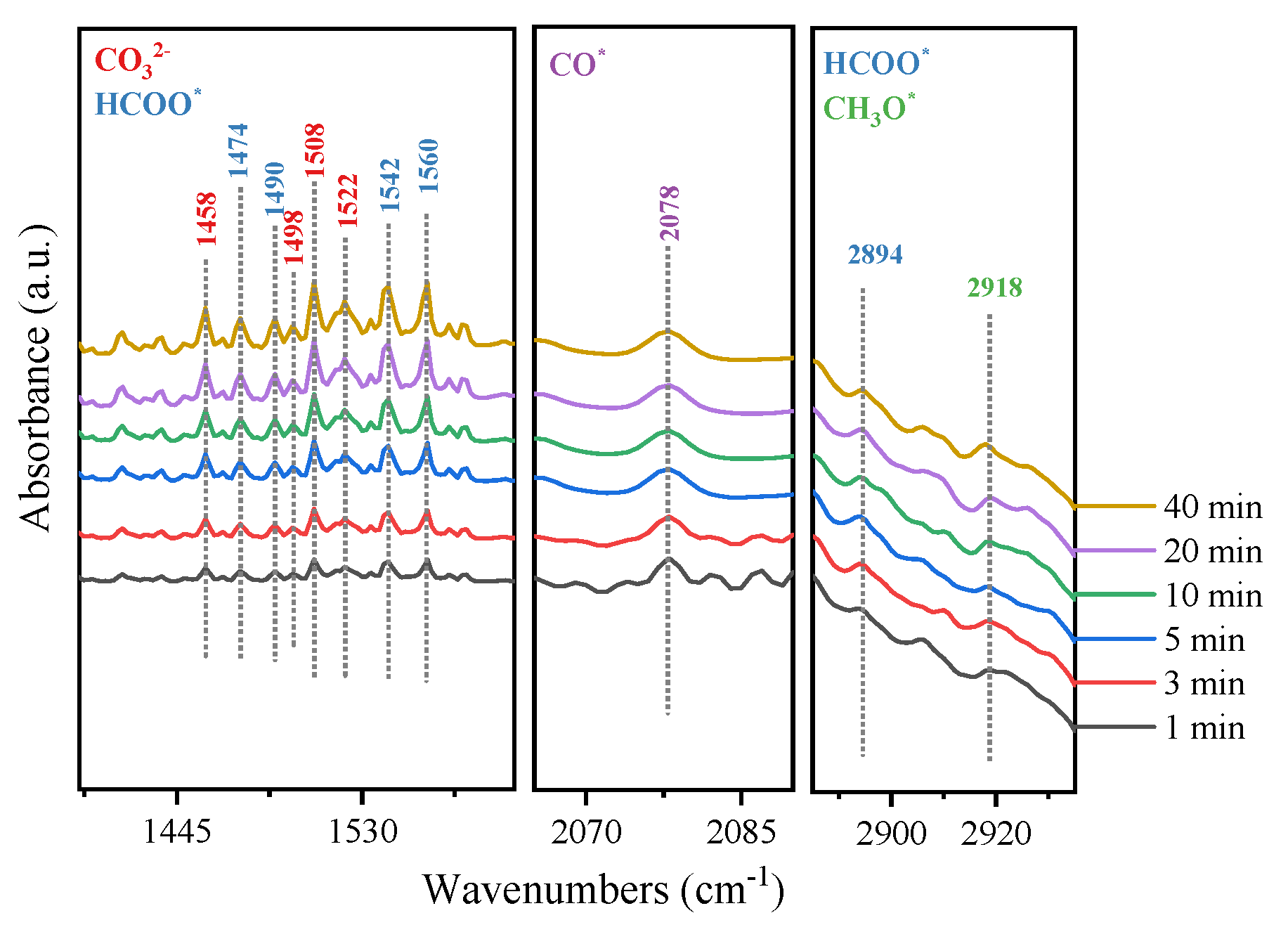
From the in situ DRIFTS, two peaks were observed at 1458 and 1522 cm−1, corresponding to carbonate species (CO32−) [64,65]. In addition, two peaks at 1498 and 1508 cm−1 were also observed, corresponding to monodentate and bidentate carbonate species [66], and their intensity gradually increased with the prolongation of the reaction time. As a result of these, CO2 first adsorbed on the surface of MoSe2@C-55 and then converted into a carbonate (CO32−) species. The C-H bond vibration of the formate species at 1490 cm−1 [67] and spectral bands at 1560, 1542, 1474 and 2894 cm−1 could be observed, corresponding to the symmetric OCO stretching vibration and the stretching vibration of the formate species [68,69,70,71]. In addition, the characteristic absorption peak at 2918 cm−1 was attributed to the vibration of the C-H bond of the CH3O* species [72]. The above results indicated that there may be a reaction path in the reaction process from CO2 hydrogenation to HCOO* species and finally to CH3OH. Specifically, the adsorbed CO2 was converted to carbonate, then HCOO* species were generated from the reaction between carbonate and hydrogen, and CH3O* was formed from the hydrogenation of the HCOO∗ species. Subsequently, CH3O* → CH3OH* → CH3OH (g) were performed. At the same time, a characteristic peak was observed at 2078 cm−1, attributed to CO* [69], which provided evidence for the dissociation of CO2 when it was adsorbed on the catalyst surface. However, CO was not detected in the reaction products when the reaction was carried out at 180 °C, suggesting that the hydrogenation of CO occurred. Therefore, there is another reaction path in CO2 hydrogenation over the MoSe2@C-55 catalyst, where the adsorbed CO2 is dissociated to CO, which is then directly hydrogenated to CH3O* and finally to CH3OH. The detailed reaction pathway is shown in Scheme 1.
3. Experiment
3.1. Materials
Ammonium molybdate ((NH4)6Mo7O24·4H2O, AMT) and glucose were obtained from Tianjin Kemiou Chemical Reagents Co., Ltd. (Tianjin, China). Selenium powder was purchased from MackLin Chemical Reagents Co., Ltd. (Shanghai, China), and sodium borohydride was obtained from Tianjin Kemiou Chemical Reagents Co., Ltd. (Tianjin, China). H2 (99.99%), N2 (99.99%), CO2 (99.99%) and 5% Ar/95% H2 (99.99%) were bought from Qinghua Gas Co., Ltd. (Harbin, China). Without further purification, all reagents were used directly.
3.2. Preparation of Catalysts
3.2.1. Preparing the MoSe2@C-55 Catalyst
Ammonium molybdate (0.4022 g) and glucose (4.1381 g) (n(C)/n(Mo) = 55) were dissolved in deionized water. After removal of the water, the prepared product was dried at 110 °C for 12 h. Subsequently, it was mixed with selenium powder (0.3598 g) and placed in a tubular furnace. In a N2 atmosphere, the temperature was increased to 700 °C at a rate of 5 °C/min for 4 h, and MoSe2 confined in carbon material catalyst (MoSe2@C-55, where 55 is the carbon–molybdenum ratio (C/Mo) in the precursor) was obtained. When the C/Mo ratio in the precursors changed to 15, 35 and 75, they were named MoSe2@-15, MoSe2@-35 and MoSe2@-75, respectively.
3.2.2. Preparing the MoSe2/C Catalyst
A total of 0.4022 g ammonium molybdate was impregnated into 1.5036 g coconut shell carbon by the impregnation method and dried at 110 °C overnight. After mixing the dried solid and 0.3598 g selenium powder, the resulting products were roasted in a tube furnace. In a H2/N2 atmosphere containing 30% H2, the temperature was raised to 700 °C at 5 °C/min for 4 h. The MoSe2/C sample was obtained.
3.2.3. Preparing the MoSe2 Catalyst
An aqueous solution containing sodium borohydride (0.3972 g) was added drop by drop to 0.5527 g selenium powder, and the mixture was stirred to form a reddish-brown solution at 70 °C. Then, the reddish-brown mixture was added to an aqueous solution containing ammonium molybdate (0.6180 g). After stirring at ambient temperature for 30 min, the mixture was put into a 50 mL stainless steel autoclave lined with PTFE and crystallized at 220 °C for 24 h, then cooled to ambient temperature. Subsequently, it was centrifuged, washed, dried and put into a tubular furnace. In a N2 atmosphere, the temperature of the tubular furnace rose to 550 °C at a rate of 5 °C/min, and it was held for 2 h. Then, it was refrigerated to ambient temperature, and the MoSe2 sample was obtained.
3.3. Characterization
X-ray powder diffraction (XRD, Bruker D8, Advance, Salbrücken, Germany) of Cu-Kα radiation diffraction (ƛ = 1.5406A) was used to characterize the crystal structure of the samples, and transmission electron microscopy (TEM, JEM-2100, Tokyo, Japan) and high-resolution transmission electron microscopy (HRTEM, JEM-2100, Tokyo, Japan) were used to observe their morphology and size. An X-ray photoelectron spectrometer (ESCALAB 250-11 OOV, Thermo Fisher, Waltham, MA, USA) was employed to determine the types and valence of the elements on their surface. CO2 temperature-programmed desorption (TPD) was carried out on a chemisorption instrument equipped with a thermal conductivity detector (TCD). The process was as follows: After pretreatment at 500 °C for 60 min in Ar (40 mL/min), the sample (0.2 g) was exposed to CO2 (40 mL/min) for 60 min while it was cooled to 50 °C. Subsequently, the physically adsorbed CO2 was eliminated in a pure Ar (40 mL/min) atmosphere for 60 min. Then, the desorption of CO2 was measured from 50 °C to 500 °C at a rate of 10 °C/min in an Ar (40 mL/min) atmosphere. On a Perkin Elmer frontier spectrometer (Waltham, MA, USA), in situ diffuse infrared Fourier transform spectroscopy (DRIFTS) measurements were carried out. Firstly, the sample was pretreated at 400 °C for 60 min with a H2 flow of 30 mL/min and then chilled to 180 °C. Subsequently, gas feed (H2 30 mL/min and CO2 10 mL/min) was introduced after scanning the background spectrum in the range of 400–4000 cm−1, and the samples were scanned four times in the first 10 min and twice in 30 min.
3.4. Catalytic Performance Evaluation
The hydrogenation of CO2 to yield methanol was performed in a fixed-bed reactor (inner diameter of 6 mm). The schematic diagram of the reaction device is shown in Figure 7. After the catalyst (0.5 g) was pretreated in pure H2 at 400 °C for 3 h and chilled to 180 °C, the feed gas (H2/CO2 ratio of 3/1) was introduced into the reactor under 3.0 MPa. The reaction tail gas was quantitatively analyzed using a gas chromatograph equipped with a hydrogen flame detector (GC-7900, Tianmei, Shanghai, China) and a thermal conductivity detector (GC-7890II, Tianmei, Shanghai, China).
4. Conclusions
MoSe2 catalysts were prepared by different loading methods and applied to carry out the hydrogenation of CO2 to methanol. The introduction of carbon materials can effectively improve the dispersion of MoSe2. When glucose was introduced into the precursor as a carbon source, small particles and a few layers of MoSe2 were formed in the MoSe2@C-55 catalyst under the confinement of the in situ-formed carbon material, which was beneficial for exposing more active sites.
Due to the strong interaction between MoSe2 and the in situ-formed carbon, the MoSe2-Mo2C heterojunction was generated, which interrupted the continuity of MoSe2. Under the confinement effect of the in situ-formed carbon material, the layer number and particle size of MoSe2 were reduced in the MoSe2@C-55 catalyst, which was conducive to exposing more active sites.
Over the MoSe2@C-55 catalyst, a higher methanol selectivity of 93.7% and excellent catalytic stability in the continuous reaction within 100 h provide a prospect for the application of the high-efficiency catalyst under the cooperation of the MoSe2-Mo2C heterojunction and the in situ-formed carbon material. The results of the in situ DRIFTS proved the HCOO* and CO* species were the intermediates for synthesizing methanol from CO2 in the presence of a MoSe2@C-55 catalyst.
Supplementary Materials
The following supporting information can be downloaded at https://www.mdpi.com/article/10.3390/molecules29102186/s1: Figure S1. XRD patterns of MoSe2@C-x catalysts prepared with different C/Mo ratios; Figure S2. TEM and HRTEM images of MoSe2@C-x catalysts prepared with different C/Mo ratios: (a,e) MoSe2@C-15; (b,f) MoSe2@C-35; (c,g) MoSe2@C-55; (d,h) MoSe2@C-75; Figure S3. Survey XPS spectra of MoSe2, MoSe2/C and MoSe2@C catalysts; Figure S4. XPS spectra of MoSe2@C-x catalysts prepared with different C/Mo ratios: (a) survey spectrum; (b) Mo 3d; (c) Se 3d; (d) C 1s; (e) O 1s; Figure S5. Activating H2 on the MoSe2-Mo2C heterojunction; Figure S6. CO2-TPD of MoSe2@C-x with different C/Mo ratios; Table S1. The valence state and distribution of the Mo element on the surface of the MoSe2, MoSe2/C and MoSe2@C catalysts; Table S2. The valence state and distribution of the Se element on the surface of the MoSe2, MoSe2/C and MoSe2@C catalysts; Table S3. The valence state and distribution of the C element on the surface of the MoSe2, MoSe2/C and MoSe2@C catalysts; Table S4. The valence state and distribution of the O element on the surface of the MoSe2, MoSe2/C and MoSe2@C catalysts; Table S5. The valence state and distribution of the Mo element on the surface of MoSe2@C-x; Table S6. The valence state and distribution of the O element on the surface of MoSe2@C-x; Table S7. Comparison betweenMoSe2@C-55 and reported catalysts in CO2 hydrogenation to methanol [73,74,75,76,77].
Author Contributions
Y.S.: Experimental operation, Data curation, Writing—original draft. L.X.: Supervision, Writing—review and editing, Project administration. W.W.: Supervision, Writing—review and editing, Project administration. All authors have read and agreed to the published version of the manuscript.
Funding
This research was funded by Basal Research Fund of Provincial Higher Education Institutions in Heilongjiang Province (2022-KYYWF-1061).
Institutional Review Board Statement
Not applicable.
Informed Consent Statement
Not applicable.
Data Availability Statement
All data generated or analyzed during this study are included in this published article.
Conflicts of Interest
The authors declare no conflicts of interest.
References
- Zhong, S.; Guo, X.; Zhou, A.; Chen, Z.; Jin, D.; Fan, M.; Ma, T. Fundamentals and recent progress in magnetic field assisted CO2 capture and conversion. Small 2024, 20, 2305533. [Google Scholar] [CrossRef] [PubMed]
- Wang, Q.; Luo, J.; Zhong, Z.; Borgna, A. CO2 capture by solid adsorbents and their applications: Current status and new trends. Energy Environ. Sci. 2011, 4, 42–55. [Google Scholar] [CrossRef]
- MacDowell, N.; Florin, N.; Buchard, A.; Hallett, J.; Galindo, A.; Jackson, G.; Adjiman, C.S.; Williams, C.K.; Shah, N.; Fennell, P. An overview of CO2 capture technologies. Energy Environ. Sci. 2010, 3, 1645–1669. [Google Scholar] [CrossRef]
- Zhang, Y.; Zhao, S.; Li, L.; Feng, J.; Li, K.; Lin, H. Integrated CO2 capture and utilization: A review of the synergistic effects of dual function materials. Catal. Sci. Technol. 2024, 14, 790–819. [Google Scholar] [CrossRef]
- Zhang, X.G.; Buthiyappan, A.; Jewaratnam, J.; Metselaar, H.S.C.; Raman, A.A.A. Bifunctional materials for integrated CO2 capture and conversion: Review on adsorbent and catalyst types, recent advances, and challenges. J. Environ. Chem. Eng. 2024, 12, 111799. [Google Scholar] [CrossRef]
- Zhang, Z.; Pan, S.-Y.; Li, H.; Cai, J.; Olabi, A.G.; Anthony, E.J.; Manovic, V. Recent advances in carbon dioxide utilization. Renew. Sustain. Energy Rev. 2020, 125, 109799. [Google Scholar] [CrossRef]
- Al-Rowaili, F.N.; Zahid, U.; Onaizi, S.; Khaled, M.; Jamal, A.; AL-Mutairi, E.M. A review for Metal-Organic Frameworks (MOFs) utilization in capture and conversion of carbon dioxide into valuable products. J. CO2 Util. 2021, 53, 101715. [Google Scholar] [CrossRef]
- Chen, S.; Liu, J.; Zhang, Q.; Teng, F.; McLellan, B.C. A critical review on deployment planning and risk analysis of carbon capture, utilization, and storage (CCUS) toward carbon neutrality. Renew. Sustain. Energy Rev. 2022, 167, 112537. [Google Scholar] [CrossRef]
- Liu, J.; Song, Y.; Guo, X.; Song, C.; Guo, X. Recent advances in application of iron-based catalysts for COx hydrogenation to value-added hydrocarbons. Chin. J. Catal. 2022, 43, 731–754. [Google Scholar] [CrossRef]
- Navarro-Jaén, S.; Virginie, M.; Bonin, J.; Robert, M.; Wojcieszak, R.; Khodakov, A.Y. Highlights and challenges in the selective reduction of carbon dioxide to methanol. Nat. Rev. Chem. 2021, 5, 564–579. [Google Scholar] [CrossRef]
- Jiang, X.; Nie, X.; Guo, X.; Song, C.; Chen, J.G. Recent advances in carbon dioxide hydrogenation to methanol via heterogeneous catalysis. Chem. Rev. 2020, 120, 7984–8034. [Google Scholar] [CrossRef]
- Sen, R.; Goeppert, A.; Prakash, G.K.S. Homogeneous hydrogenation of CO2 and CO to methanol: The renaissance of low-temperature catalysis in the context of the methanol economy. Angew. Chem. Int. Ed. 2022, 61, e202207278. [Google Scholar] [CrossRef] [PubMed]
- Deka, T.J.; Osman, A.I.; Baruah, D.C.; Rooney, D.W. Methanol fuel production, utilization, and techno-economy: A review. Environ. Chem. Lett. 2022, 20, 3525–3554. [Google Scholar] [CrossRef]
- Onishi, N.; Himeda, Y. Homogeneous catalysts for CO2 hydrogenation to methanol and methanol dehydrogenation to hydrogen generation. Coord. Chem. Rev. 2022, 472, 214767. [Google Scholar] [CrossRef]
- Sheetal; Mehara, P.; Das, P. Methanol as a greener C1 synthon under non-noble transition metal-catalyzed conditions. Coord. Chem. Rev. 2023, 475, 214851. [Google Scholar] [CrossRef]
- Bowker, M. Methanol synthesis from CO2 hydrogenation. ChemCatChem 2019, 11, 4238–4246. [Google Scholar] [CrossRef] [PubMed]
- LBobadilla, F.; Azancot, L.; González-Castaño, M.; Ruíz-López, E.; Pastor-Pérez, L.; Durán-Olivencia, F.-J.; Odriozola, J.-A. Biomass gasification, catalytic technologies and energy integration for production of circular methanol: New horizons for industry decarbonisation. J. Environ. Sci. 2024, 140, 306–318. [Google Scholar] [CrossRef] [PubMed]
- Qi, S.C.; Liu, X.Y.; Zhu, R.R.; Xue, D.M.; Liu, X.Q.; Sun, L.B. Causation of catalytic activity of Cu-ZnO for CO2 hydrogenation to methanol. Chem. Eng. J. 2022, 430, 132784. [Google Scholar] [CrossRef]
- Qi, T.; Li, W.; Li, H.; Ji, K.; Chen, S.; Zhang, Y. Yttria-doped Cu/ZnO catalyst with excellent performance for CO2 hydrogenation to methanol. Mol. Catal. 2021, 509, 111641. [Google Scholar] [CrossRef]
- Guo, H.; Li, Q.; Zhang, H.; Peng, F.; Xiong, L.; Yao, S.; Huang, C.; Chen, X. CO2 hydrogenation over acid-activated Attapulgite/Ce0.75Zr0.25O2 nanocomposite supported Cu-ZnO based catalysts. Mol. Catal. 2019, 476, 110499. [Google Scholar] [CrossRef]
- Sha, F.; Han, Z.; Tang, S.; Wang, J.; Li, C. Hydrogenation of carbon dioxide to methanol over Non-Cu-based heterogeneous catalysts. ChemSusChem 2020, 13, 6160–6181. [Google Scholar] [CrossRef] [PubMed]
- Martin, O.; Martín, A.J.; Mondelli, C.; Mitchell, S.; Segawa, T.F.; Hauert, R.; Drouilly, C.; Curulla-Ferré, D.; Pérez-Ramírez, J. Indium oxide as a superior catalyst for methanol synthesis by CO2 hydrogenation. Angew. Chem. Int. Ed. 2016, 55, 6261–6265. [Google Scholar] [CrossRef] [PubMed]
- Wang, J.; Li, G.; Li, Z.; Tang, C.; Feng, Z.; An, H.; Liu, H.; Liu, T.; Li, C. A highly selective and stable ZnO-ZrO2 solid solution catalyst for CO2 hydrogenation to methanol. Sci. Adv. 2017, 3, e1701290. [Google Scholar] [CrossRef] [PubMed]
- Levy, R.B.; Boudart, M. Platinum-like behavior of tungsten carbide in surface catalysis. Sci. New Ser. 1973, 181, 547–549. [Google Scholar] [CrossRef] [PubMed]
- Ma, F.; Wu, H.B.; Xia, B.Y.; Xu, C.; Lou, X.W. Hierarchical β-Mo2C nanotubes organized by ultrathin nanosheets as a highly efficient electrocatalyst for hydrogen production. Angew. Chem. Int. Ed. 2015, 54, 15395–15399. [Google Scholar] [CrossRef] [PubMed]
- Akmach, D.; Bathla, S.; Tran, C.C.; Kaliaguine, S.; Mushrif, S.H. Transition metal carbide catalysts for Upgrading lignocellulosic biomass-derived oxygenates: A review of the experimental and computational investigations into structure-property relationships. Catal. Today 2023, 423, 114285. [Google Scholar] [CrossRef]
- Jujjuri, S.; Cárdenas-Lizana, F.; Keane, M.A. Synthesis of group VI carbides and nitrides: Application in catalytic hydrodechlorination. J. Mater. Sci. 2014, 49, 5406–5417. [Google Scholar] [CrossRef]
- Qiu, Z.; Wang, Y.; Li, Z.; Cao, Y.; Li, Q. Hydrodenitrogenation of Quinoline with high selectivity to aromatics over α-MoC1-x. Mol. Catal. 2021, 516, 112002. [Google Scholar] [CrossRef]
- Dubois, J.-L.; Sayama, K.; Arakawa, H. CO2 hydrogenation over carbide catalysts. Chem. Lett. 1992, 21, 5–8. [Google Scholar] [CrossRef]
- Posada-Pérez, S.; Viñes, F.; Ramirez, P.J.; Vidal, A.B.; Rodriguez, J.A.; Illas, F. The bending machine: CO2 activation and hydrogenation on δ-MoC(001) and β-Mo2C(001) surfaces. Phys. Chem. Chem. Phys. 2014, 16, 14912–14921. [Google Scholar] [CrossRef]
- Han, H.; Cui, P.; Xiao, L.; Wu, W. MoCS@NSC with interfacial heterostructure nanostructure: A highly selective catalyst for synthesizing methanol from CO2 at low temperature. J. Environ. Chem. Eng. 2021, 9, 106354. [Google Scholar] [CrossRef]
- Hu, J.; Yu, L.; Deng, J.; Wang, Y.; Cheng, K.; Ma, C.; Zhang, Q.; Wen, W.; Yu, S.; Pan, Y.; et al. Sulfur vacancy-rich MoS2 as a catalyst for the hydrogenation of CO2 to methanol. Nat. Catal. 2021, 4, 242–250. [Google Scholar] [CrossRef]
- Sharma, M.D.; Mahala, C.; Basu, M. 2D thin sheet heterostructures of MoS2 on MoSe2 as efficient electrocatalyst for hydrogen evolution reaction in wide ph range. Inorg. Chem. 2020, 59, 4377–4388. [Google Scholar] [CrossRef] [PubMed]
- Wazir, M.B.; Daud, M.; Safeer, S.; Almarzooqi, F.; Qurashi, A. Review on 2D molybdenum diselenide (MoSe2) and its hybrids for green hydrogen (H2) generation applications. ACS Omega 2022, 7, 16856–16865. [Google Scholar] [CrossRef] [PubMed]
- Xu, J.; Li, X.; Liu, W.; Sun, Y.; Ju, Z.; Yao, T.; Wang, C.; Ju, H.; Zhu, J.; Wei, S.; et al. Carbon Dioxide electroreduction into syngas boosted by a partially delocalized charge in molybdenum sulfide selenide alloy monolayers. Angew. Chem. Int. Ed. 2019, 56, 9121–9125. [Google Scholar] [CrossRef] [PubMed]
- Qu, H.; He, S.; Su, Y.; Zhang, Y.; Su, H. MoSe2: A promising non-noble metal catalyst for direct ethanol synthesis from syngas. Fuel 2020, 281, 118760. [Google Scholar] [CrossRef]
- Zhao, G.-Q.; Long, X.; Zou, J.; Hu, J.; Jiao, F.-P. Design of hollow nanostructured photocatalysts for clean energy production. Coord. Chem. Rev. 2023, 477, 214953. [Google Scholar] [CrossRef]
- Dai, M.; Wang, R. Synthesis and applications of nanostructured hollow transition metal chalcogenides. Small 2021, 17, 2006813. [Google Scholar] [CrossRef] [PubMed]
- Liu, Y.; Zhu, M.; Chen, D. Sheet-like MoSe2/C composites with enhanced Li-ion storage properties. J. Mater. Chem. A 2015, 3, 11857–11862. [Google Scholar] [CrossRef]
- Zhang, X.; Xiong, Y.; Dong, M.; Hou, Z.; Qian, Y. Construction of hierarchical MoSe2@C hollow nanospheres for efficient lithium/sodium ion storage. Inorg. Chem. Front. 2020, 7, 1691–1698. [Google Scholar] [CrossRef]
- Liu, H.; Liu, B.; Guo, H.; Liang, M.; Zhang, Y.; Borjigin, T.; Yang, X.; Wang, L.; Sun, X. N-doped C-encapsulated scale-like yolk-shell frame assembled by expanded planes few-layer MoSe2 for enhanced performance in sodium-ion batteries. Nano Energy 2018, 51, 639–648. [Google Scholar] [CrossRef]
- Tang, H.; Dou, K.; Kaun, C.C.; Kuang, Q.; Yang, S. MoSe2 nanosheets and their graphene hybrids: Synthesis, characterization and hydrogen evolution reaction studies. J. Mater. Chem. A 2014, 2, 360–364. [Google Scholar] [CrossRef]
- Guan, D.; Shi, C.; Xu, H.; Gu, Y.; Zhong, J.; Sha, Y.; Shao, Z. Simultaneously mastering operando strain and reconstruction effects via phase-segregation strategy for enhanced oxygen-evolving electrocatalysis. J. Energy Chem. 2023, 82, 572–580. [Google Scholar] [CrossRef]
- Chen, B.; Meng, Y.; He, F.; Liu, E.; Shi, C.; He, C.; Ma, L.; Li, Q.; Li, J.; Zhao, N. Thermal decomposition-reduced layer-by-layer nitrogen-doped graphene/MoS2/nitrogen-doped graphene heterostructure for promising lithium-ion batteries. Nano Energy 2017, 41, 154–163. [Google Scholar] [CrossRef]
- Niu, F.; Yang, J.; Wang, N.; Zhang, D.; Fan, W.; Yang, J.; Qian, Y. MoSe2-covered n, p-doped carbon nanosheets as a long-life and high-rate anode material for sodium-ion batteries. Adv. Funct. Mater. 2017, 27, 1700522. [Google Scholar] [CrossRef]
- Balati, A.; Bazilio, A.; Shahriar, A.; Nash, K.; Shipley, H.J. Simultaneous formation of ultra-thin MoSe2 nanosheets, inorganic fullerene-like MoSe2 and MoO3 quantum dots using fast and ecofriendly pulsed laser ablation in liquid followed by microwave treatment. Mater. Sci. Semicond. Process. 2019, 99, 68–77. [Google Scholar] [CrossRef]
- Qu, B.; Li, C.; Zhu, C.; Wang, S.; Zhang, X.; Chen, Y. Growth of MoSe2 nanosheets with small size and expanded spaces of (002) plane on the surfaces of porous N-doped carbon nanotubes for hydrogen production. Nanoscale 2016, 8, 16886–16893. [Google Scholar] [CrossRef] [PubMed]
- Vikraman, D.; Hussain, S.; Karuppasamy, K.; Feroze, A.; Kathalingam, A.; Sanmugam, A.; Chun, S.H.; Jung, J.; Kim, H.S. Engineering the novel MoSe2-Mo2C hybrid nanoarray electrodes for energy storage and water splitting applications. Appl. Catal. B Environ. 2020, 264, 118531. [Google Scholar] [CrossRef]
- Ge, P.; Hou, H.; Banks, C.E.; Foster, C.W.; Li, S.; Zhang, Y.; He, J.; Zhang, C.; Ji, X. Binding MoSe2 with carbon constrained in carbonous nanosphere towards high-capacity and ultrafast Li/Na-ion storage. Energy Storage Mater. 2018, 12, 310–323. [Google Scholar] [CrossRef]
- Liu, H.; Guo, H.; Liu, B.; Liang, M.; Lv, Z.; Adair, K.R.; Sun, X. Few-layer MoSe2 nanosheets with expanded (002) planes confined in hollow carbon nanospheres for ultrahigh-performance Na-ion batteries. Adv. Funct. Mater. 2018, 28, 1707480. [Google Scholar] [CrossRef]
- Li, J.; Hong, W.; Jian, C.; Cai, Q.; He, X.; Liu, W. High-performance hydrogen evolution at a MoSe2–Mo2C seamless heterostructure enabled by efficient charge transfer. J. Mater. Chem. A 2020, 8, 6692–6698. [Google Scholar] [CrossRef]
- Su, J.; Nie, Z.; Feng, Y.; Hu, X.; Li, H.; Zhao, Z.; Zan, S.; Qi, S. Hollow core-shell structure Co/C@MoSe2 composites for high-performance microwave absorption. Compos. Part A Appl. Sci. Manuf. 2022, 162, 107140. [Google Scholar] [CrossRef]
- Tang, J.; Huang, C.; Wu, Q.; Cui, A.; Li, W. Atomic-scale intercalation of N-doped carbon into monolayered MoSe2-Mo2C heterostructure as a highly efficiency hydrogen evolution reaction catalyst. J. Electroanal. Chem. 2022, 906, 115897. [Google Scholar] [CrossRef]
- Zhang, L.; Cao, X.; Feng, C.; Zhang, W.; Wang, Z.; Feng, S.; Huang, Z.; Lu, X.; Dai, F. Interfacial Mo-N-C bond endowed hydrogen evolution reaction on MoSe2@N-Doped carbon hollow nanoflowers. Inorg. Chem. 2021, 60, 12377–12385. [Google Scholar] [CrossRef] [PubMed]
- Huang, H.; Cui, J.; Liu, G.; Bi, R.; Zhang, L. Carbon-coated MoSe2/MXene hybrid nanosheets for superior potassium storage. ACS Nano 2019, 13, 3448–3456. [Google Scholar] [CrossRef] [PubMed]
- Zhang, H.; Guan, D.; Gu, Y.; Xu, H.; Wang, C.; Shao, Z.; Guo, Y. Tuning synergy between nickel and iron in Ruddlesden-Popper perovskites through controllable crystal dimensionalities towards enhanced oxygen-evolving activity and stability. Carbon Energy 2024, 6, e465. [Google Scholar] [CrossRef]
- Zhang, Y.; He, Y.; Cao, M.; Liu, B.; Li, J. High selective methanol synthesis from CO2 hydrogenation over Mo-Co-C-N catalyst. Fuel 2022, 325, 124854. [Google Scholar] [CrossRef]
- Ma, Z.-Y.; Yang, C.; Wei, W.; Li, W.-H.; Sun, Y.-H. Surface properties and CO adsorption on zirconia polymorphs. J. Mol. Catal. A Chem. 2005, 227, 119–124. [Google Scholar] [CrossRef]
- Dong, X.; Li, F.; Zhao, N.; Xiao, F.; Wang, J.; Tan, Y. CO2 hydrogenation to methanol over Cu/ZnO/ZrO2 catalysts prepared by precipitation-reduction method. Appl. Catal. B Environ. 2016, 191, 8–17. [Google Scholar] [CrossRef]
- Zhou, Y.; Liu, F.; Geng, S.; Yao, M.; Ma, J.; Cao, J. Tuning the content of S vacancies in MoS2 by Cu doping for enhancing catalytic hydrogenation of CO2 to methanol. Mol. Catal. 2023, 547, 113288. [Google Scholar] [CrossRef]
- Yang, Z.; He, Y.; Tang, P.; Xu, C.; Zhang, G.; He, J. Oxygen-incorporated 3D flower-like MoS2 microsphere as a bifunctional catalyst for effective synthesis of 2,5-diformyfuran from fructose. Catal. Sci. Technol. 2023, 13, 2340–2348. [Google Scholar] [CrossRef]
- Zhang, P.; Na, W.; Zuo, J.; Wen, J.; Huang, Z.; Huang, H.; Gao, W.; Qi, X.; Zheng, M.; Wang, H. CO2 hydrogenation to methanol over hydrothermally synthesized Inx-Zry catalysts. Mol. Catal. 2023, 538, 112977. [Google Scholar] [CrossRef]
- Heracleous, E.; Koidi, V.; Lappas, A.A. Experimental Investigation of Sorption-Enhanced CO2 Hydrogenation to Methanol. ACS Sustain. Chem. Eng. 2023, 11, 9684–9695. [Google Scholar]
- Wei, Y.; Liu, F.; Ma, J.; Yang, C.; Wang, X.; Cao, J. Catalytic roles of In2O3 in ZrO2-based binary oxides for CO2 hydrogenation to methanol. Mol. Catal. 2022, 525, 112354. [Google Scholar] [CrossRef]
- Daifeng, L.; Zhen, Z.; Yinye, C.; Lingxing, Z.; Xiaochuan, C.; Xuhui, Y.; Baoquan, H.; Yongjin, L.; Qingrong, Q.; Qinghua, C. The Co-In2O3 interaction concerning the effect of amorphous Co metal on CO2 hydrogenation to methanol. J. CO2 Util. 2022, 65, 102209. [Google Scholar] [CrossRef]
- Rasteiro, L.F.; De Sousa, R.A.; Vieira, L.H.; Ocampo-Restrepo, V.K.; Verga, L.G.; Assaf, J.M.; Da Silva, J.L.F.; Assaf, E.M. Insights into the alloy-support synergistic effects for the CO2 hydrogenation towards methanol on oxide-supported Ni5Ga3 catalysts: An experimental and DFT study. Appl. Catal. B Environ. 2022, 302, 120842. [Google Scholar] [CrossRef]
- Alabsi, M.H.; Chen, X.; Wang, X.; Zhang, M.; Ramirez, A.; Duan, A.; Xu, C.; Cavallo, L.; Huang, K.W. Highly dispersed Pd nanoparticles supported on dendritic mesoporous CeZrZnOx for efficient CO2 hydrogenation to methanol. J. Catal. 2022, 413, 751–761. [Google Scholar] [CrossRef]
- Wang, Y.; Yu, H.; Hu, Q.; Huang, Y.; Wang, X.; Wang, Y.; Wang, F. Application of microimpinging stream reactor coupled with ultrasound in Cu/CeZrOx solid solution catalyst preparation for CO2 hydrogenation to methanol. Renew. Energy 2023, 202, 834–843. [Google Scholar] [CrossRef]
- Zhou, S.; Zeng, H.C. Boxlike Assemblages of few-layer MoS2 nanosheets with edge blockage for high-efficiency hydrogenation of CO2 to methanol. ACS Catal. 2022, 12, 9872–9886. [Google Scholar] [CrossRef]
- Chen, G.; Yu, J.; Li, G.; Zheng, X.; Mao, H.; Mao, D. Cu+-ZrO2 interfacial sites with highly dispersed copper nanoparticles derived from Cu@UiO-67 hybrid for efficient CO2 hydrogenation to methanol. Int. J. Hydrogen Energy 2023, 48, 2605–2616. [Google Scholar] [CrossRef]
- Wang, Y.; Zhang, X.; Hong, X.; Liu, G. Sulfate-promoted higher alcohol synthesis from CO2 hydrogenation. ACS Sustain. Chem. Eng. 2022, 10, 8980–8987. [Google Scholar]
- Marcos, F.C.F.; Alvim, R.S.; Lin, L.; Betancourt, L.E.; Petrolini, D.D.; Senanayake, S.D.; Alves, R.M.B.; Assaf, J.M.; Rodriguez, J.A.; Giudici, R.; et al. The role of copper crystallization and segregation toward enhanced methanol synthesis via CO2 hydrogenation over CuZrO2 catalysts: A combined experimental and computational study. Chem. Eng. J. 2023, 452, 139519. [Google Scholar] [CrossRef]
- Zhou, S.; Kosari, M.; Zeng, H.C. Boosting CO2 hydrogenation to methanol over monolayer MoS2 nanotubes by creating more strained basal planes. J. Am. Chem. Soc. 2024, 146, 10032–10043. [Google Scholar] [CrossRef]
- Zhou, S.; Ma, W.; Anjum, U.; Kosari, M.; Xi, S.; Kozlov, S.M.; Zeng, H.C. Strained few-layer MoS2 with atomic copper and selectively exposed in-plane sulfur vacancies for CO2 hydrogenation to methanol. Nat. Commun. 2023, 14, 5872. [Google Scholar] [CrossRef] [PubMed]
- Yuan, Y.; Qi, L.; Gao, Z.; Guo, T.; Zhai, D.; He, Y.; Guo, Q. Performance exploration of Ni-doped MoS2 in CO2 hydrogenation to methanol. Molecules 2023, 28, 5796. [Google Scholar] [CrossRef] [PubMed]
- Zou, R.; Shen, C.; Sun, K.; Ma, X.; Ma, X.; Li, Z.; Li, M.; Liu, C.J. CO2 hydrogenation to methanol over the copper promoted In2O3 catalyst. J. Energy. Chem. 2024, 93, 135–145. [Google Scholar] [CrossRef]
- Wang, J.; Song, Y.; Li, J.; Liu, F.; Wang, J.; Lv, J.; Ma, X. Modulation of Al2O3 and ZrO2 composite in Cu/ZnO-based catalysts with enhanced performance for CO2 hydrogenation to methanol. Appl. Catal. A 2024, 674, 119618. [Google Scholar] [CrossRef]
Figure 1.
XRD patterns of MoSe2, MoSe2/C and MoSe2@C-55 catalysts.
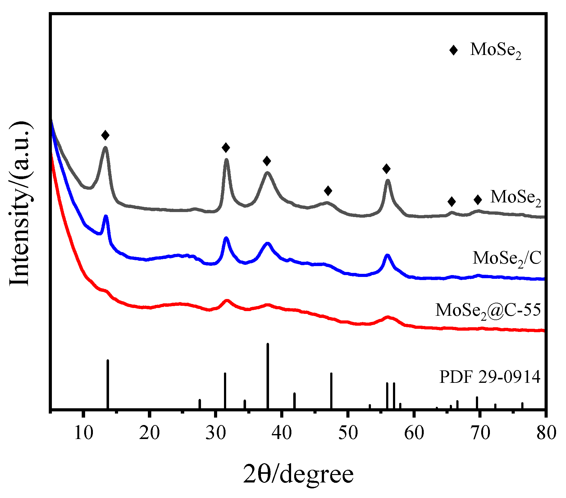
Figure 2.
TEM and HRTEM images of MoSe2/C and MoSe2@C-55 catalysts: (a,b) MoSe2/C; (c,d) MoSe2@C-55.
Figure 2.
TEM and HRTEM images of MoSe2/C and MoSe2@C-55 catalysts: (a,b) MoSe2/C; (c,d) MoSe2@C-55.

Figure 3.
XPS spectra of MoSe2, MoSe2/C and MoSe2@C catalysts: (a) Mo 3d; (b) Se 3d; (c) C 1s; (d) O 1s.
Figure 3.
XPS spectra of MoSe2, MoSe2/C and MoSe2@C catalysts: (a) Mo 3d; (b) Se 3d; (c) C 1s; (d) O 1s.
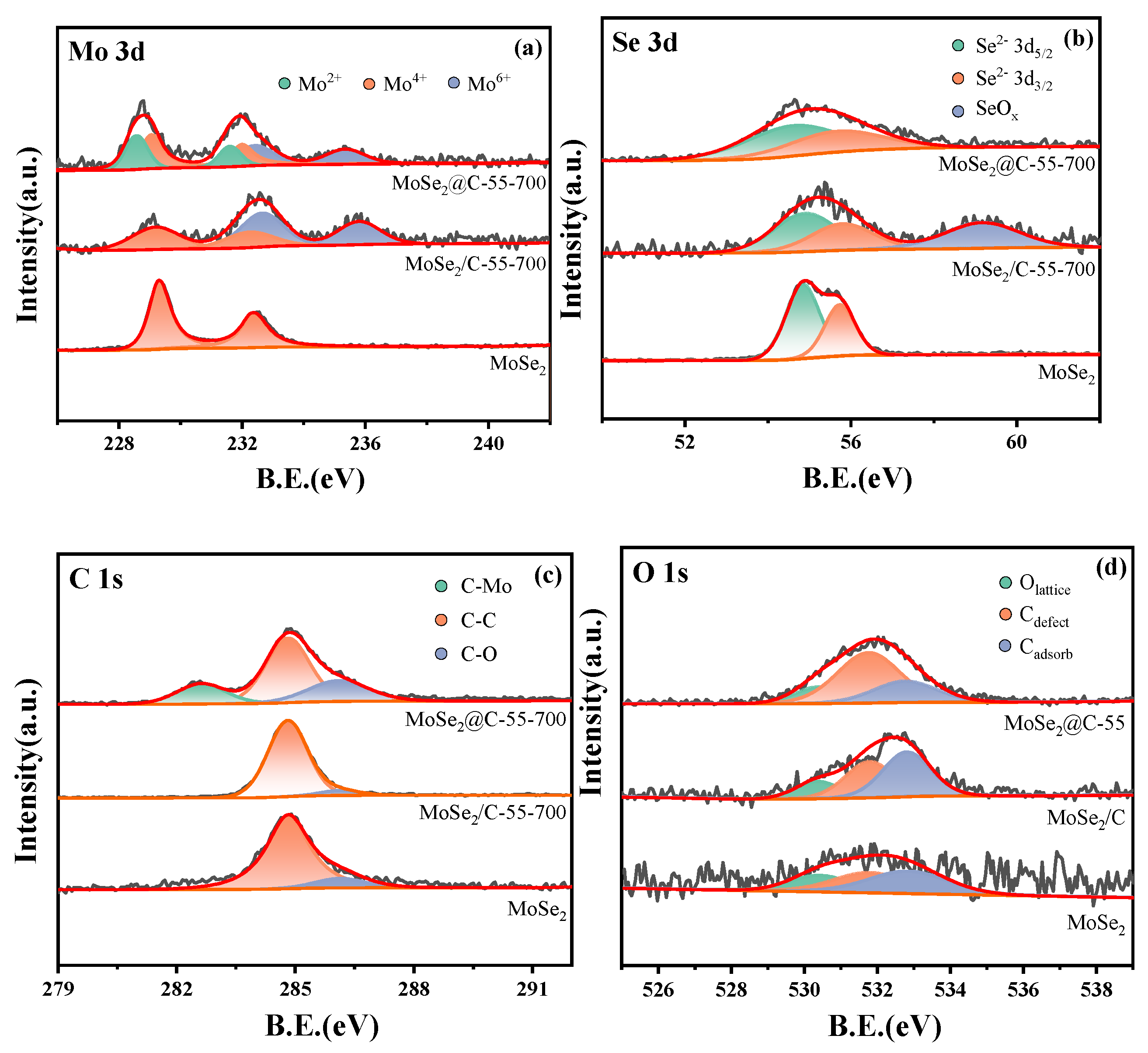
Figure 4.
CO2-TPD profiles of MoSe2, MoSe2/C and MoSe2@C-55 catalysts.

Figure 5.
Catalytic performance of hydrogenation of CO2 over MoSe2@C-55 under different conditions: (a) effect of temperature; (b) effect of pressure; (c) effect of space velocity; (d) stability evaluation.
Figure 5.
Catalytic performance of hydrogenation of CO2 over MoSe2@C-55 under different conditions: (a) effect of temperature; (b) effect of pressure; (c) effect of space velocity; (d) stability evaluation.

Figure 6.
DRIFTS spectra of CO2 hydrogenation in the presence of MoSe2@C-55.
Scheme 1.
Supposed reaction path of CO2 hydrogenation to methanol in the presence of MoSe2@C-55.

Figure 7.
Schematic diagram of the reaction device.


Table 1.
Results of CO2 hydrogenation to methanol over different catalysts a.
| Catalyst | Conversion (%) | Selectivity (%) | |||
|---|---|---|---|---|---|
| CH3OH | CH4 | CO | CH3OCH3 | ||
| MoSe2 | 2.4 | 52.5 | 10.2 | 33.1 | 4.2 |
| MoSe2/C | 4.3 | 89.9 | 10.1 | - | - |
| MoSe2@C-55 | 9.7 | 93.7 | 6.3 | - | - |
| MoSe2@C-15 | 2.8 | 72.3 | 27.7 | - | - |
| MoSe2@C-35 | 3.3 | 89.5 | 10.5 | - | - |
| MoSe2@C-75 | 4.4 | 94.3 | 5.7 | - | - |
a Reaction conditions: 180 °C, 3 MPa, GHSV 3000 mL·gcat−1·h−1, H2:CO2 = 3.
Disclaimer/Publisher’s Note: The statements, opinions and data contained in all publications are solely those of the individual author(s) and contributor(s) and not of MDPI and/or the editor(s). MDPI and/or the editor(s) disclaim responsibility for any injury to people or property resulting from any ideas, methods, instructions or products referred to in the content. |
© 2024 by the authors. Licensee MDPI, Basel, Switzerland. This article is an open access article distributed under the terms and conditions of the Creative Commons Attribution (CC BY) license (https://creativecommons.org/licenses/by/4.0/).
Share and Cite
MDPI and ACS Style
Sun, Y.; Xiao, L.; Wu, W. In Situ Carbon-Confined MoSe2 Catalyst with Heterojunction for Highly Selective CO2 Hydrogenation to Methanol. Molecules 2024, 29, 2186. https://doi.org/10.3390/molecules29102186
AMA Style
Sun Y, Xiao L, Wu W. In Situ Carbon-Confined MoSe2 Catalyst with Heterojunction for Highly Selective CO2 Hydrogenation to Methanol. Molecules. 2024; 29(10):2186. https://doi.org/10.3390/molecules29102186
Chicago/Turabian StyleSun, Yanyang, Linfei Xiao, and Wei Wu. 2024. "In Situ Carbon-Confined MoSe2 Catalyst with Heterojunction for Highly Selective CO2 Hydrogenation to Methanol" Molecules 29, no. 10: 2186. https://doi.org/10.3390/molecules29102186