
AC Direct Charging for Electric Vehicles via a Reconfigurable Cascaded Multilevel Converter


Department of Electrical, Computer and Biomedical Engineering, University of Pavia, 27100 Pavia, Italy
*
Author to whom correspondence should be addressed.
†
These authors contributed equally to this work.
Energies 2024, 17(10), 2428; https://doi.org/10.3390/en17102428
Submission received: 20 April 2024
/
Revised: 14 May 2024
/
Accepted: 16 May 2024
/
Published: 19 May 2024
(This article belongs to the Special Issue Energy Management Systems of Electric Vehicles: New Trends and Dynamic Futures)
Abstract
:This paper presents a charging architecture for the Reconfigurable Cascaded Multilevel converter, which was specifically designed for electric vehicle (EV) powertrain applications. The RCMC topology is capable of executing power conversion and actively managing battery systems concurrently. The active battery management is achieved using the Reconfigurable Battery Module, which regulates the serial connection of cells via a switch pattern. In this paper, the RCMC is directly interfaced with an AC three-phase power system, facilitating the dynamic control over battery cells charging. Its inherent design allows for the implementation of various charging algorithms, customizable to specific requirements, without necessitating additional intermediary power stages. Firstly, an overview of the RCMC topology is given, and an analysis to define the optimal filter inductance is carried out. Subsequently, after the AC system characteristics are explained, two charging algorithms are presented and described: one prioritizes State of Charge (SOC) balancing among battery cells, while the other focuses on minimizing power losses. Moreover, a time estimation computation for the RCMC is carried out considering a two-level AC charging station. The result is compared with the time required for a conventional battery pack. The results show a reduction of 10 s in charging time for a mere 20% increase in SOC. Finally, the experimental setup is presented and used to validate the efficacy of the proposed algorithms.
1. Introduction
In 2023, global energy-related CO2 emissions increased by 1.1%, adding 410 million tonnes (Mt) to reach a new record high of 37.4 billion tonnes (Gt). The absence of significant advancements in pivotal clean energy technologies—i.e., wind power, solar PV, and electric cars—would have resulted in emissions growth that was three times larger [1]. As an imperative consequence, the pervasive integration of electric vehicles (EVs) has emerged as a crucial mitigating factor in reducing emissions within the transportation sector. However, major concerns for potential EV buyers include the high costs, range anxiety due to limited driving distances, long charging times and a scarcity of charging stations [2]. Substantial investments have been made to expand the number and reach of charging stations. In 2023, spending on electrified transport, including vehicles and charging infrastructures, amounted to USD 634 billion, marking a 36% increase compared to the previous year [3].
Presently, DC fast and ultra-fast chargers are available in capacities ranging from 50 kW to over 350 kW [4]. Modern DC fast chargers supply DC current to EV batteries and ensure galvanic isolation for safety [5] with a two-stage power conversion process. A three-phase AC voltage is converted to an intermediate DC voltage—with power factor correction—which is regulated to charge the EV battery pack. For higher power requirements, multiple charger modules can be paralleled [6].
Although off-board DC chargers are considered key-enable technology to increase the charging points and spread the adoption of EVs, they may encounter several drawbacks. Designing converters for ultra-fast battery chargers is highly challenging, requiring a balance of efficiency, power density, reliability, cost, isolation and a wide voltage range. High power transfer in limited space necessitates effective heat dissipation; on the other hand, maintaining clean grid currents and low ripple in battery charging currents demands complex control strategies. Additionally, the widespread use of these chargers impacts the electrical grid by introducing high, unpredictable loads, leading to transformer overload, increased losses, higher operational costs, and potential issues with grid stability and power quality [7].
Therefore, existing EV Level 1 and 2 chargers still maintain a fundamental role for EV charging processes, particularly in scenarios where rapid infrastructure expansion may not be feasible or cost-effective. Level 1 and Level 2 chargers are used mainly for residential overnight charging or commercial settings, providing 110 Vac and 230 Vac with a peak power of 1.9 kW and 19.2 kW, respectively [8]. The charging process is performed in this case through On-Board Chargers (OBCs), which are dedicated to interface the AC grid with the DC battery voltage. Specifically, they are composed of a Power Factor Circuit (PFC) and a DC/DC converter to adapt the voltage value. The initial OBCs were stand-alone, involving a specialized power electronic converter exclusively designed for battery charging. Nevertheless, the ability for power transfer is often restricted by various constraints and trade-offs, including considerations such as cost, volume, and weight of the vehicle [9].
To mitigate the limitations posed by traditional OBCs, integrated OBCs (IOBCs) utilize the existing components of the propulsion circuit, the motor and inverter, for battery charging. This approach eliminates the need for a separate charging circuit and bulky additional inductors [10]. Additionally, the current rating of the traction drive in IOBCs allows for higher charging power compared to stand-alone counterparts [11]. In [12], the main IOBC topologies are described and explained.
While substantial progress has been made in On-Board Charger (OBC) technology over the past two decades, less attention has been given to optimizing the charging processes of multilevel converters used as traction inverters. The integration of multilevel converters (MLCs) in electric vehicle (EV) powertrains is widely championed for their substantial advancements in power quality and efficiency [13]. Beyond these benefits, MLCs assume a crucial role in optimizing the management of the battery system, notably the most expensive and critical component in Battery Electric Vehicles (BEVs). By enabling the segmentation of the fixed battery pack into multiple modules, down to the individual cell level [14,15], MLCs facilitate precise control and monitoring of the battery health and performance [16]. This strategic integration not only enhances fault-tolerant control and overall system reliability [17] but also significantly contributes to addressing environmental concerns and streamlining the production phase of BEVs, which still contend with a 50% higher environmental footprint during production compared to traditional gasoline and diesel vehicles with battery manufacturing accounting for one-third of the total impact [18].
Despite these advantages, challenges emerge during the DC charging process, particularly with the structural limitations of certain MLC topologies. Notably, multilevel converters with three output terminals, such as Cascaded H-Bridge (CHB) [19], Hybrid Cascaded Modular Converter (HCMC) [20] and Reconfigurable Cascaded Multilevel Converter (RCMC) [15], would ideally require a number of isolated DC/DC converters equal to their battery cells. In [20], DC charging is exclusively performed in a single-phase configuration, and in [21], the authors propose a parallel connection between the two terminals of the DC charger and the three phases of a Cascaded H-Bridge, implementing control over the maximum current flowing through the three phases. Nevertheless, there is still a paucity of studies addressing the charging process involving the direct connection of MLCs three-output terminals to a three-phase grid, be it isolated or non-isolated.
This paper presents a charging architecture suitable for all three-output terminal multilevel converters and strategically proved on the RCMC as an extension of the work [22]. The battery arrangement adopts Reconfigurable Battery Modules (RBMs), wherein three battery cells are connected in series via seven strategically positioned switches. Cell-level control integrates Battery Management System (BMS) functionalities with power converter demands, enabling swift and efficient voltage balancing during both charging and discharging phases. The RCMC facilitates DC/AC conversion by concurrently managing Reconfigurable Battery Modules (RBMs) and H-Bridge switches, fulfilling current and voltage requirements thanks to its large voltage levels. Specifically, the RCMC is assumed to be adopted as a traction inverter, and it is here used to control the charging process. The novelty consists of the direct connection between the AC system and the powertrain converter through an inductor filter. The galvanic isolation, required for the onboard chargers, is assumed to be within the EVSE (Electric Vehicle Supply Equipment) control box. Compared to previous works, no OBC is required because the charging process is completely managed by the control of the powertrain converter. The technical ability of the RCMC to dynamically reconfigure itself allows for enhancing the charging process even when starting with a significant SOC imbalance. In this regard, two different charging algorithms are proposed to optimize the SOC balancing or the loss reduction, respectively.
The paper is structured as follows. Section 2 gives an overview of the RCMC topology, while Section 3 describes the AC system requirement and outlines the filter design. In Section 4, both charging algorithms are described, and simulation results are provided to assess their effectiveness. Section 5 carries out a comparative analysis of the charging process duration, assuming both the conventional battery pack and RCMC are connected to a two-level AC charging station. Section 6 describes the experimental results and provides the algorithm tests as validation. Section 7 concludes the paper.
2. Overview of Reconfigurable Cascaded Multilevel Converter
The proposed Reconfigurable Cascaded Multilevel Converter (RCMC), shown in the green square in Figure 1, features a distinctive design. Each phase comprises multiple submodules (SMs) arranged in a serial configuration. Within each SM, cells are structured into Reconfigurable Battery Modules (RBMs) with their terminals linked to an H-bridge (HB) converter for voltage inversion. To elevate the SM-rated voltage, a customized number of RBMs can be serially connected. Central to this design is the Reconfigurable Battery Module comprising three battery cells and seven interconnected switches, allowing flexible cell selection. The SM and RBM structures are shown in Figure 2a and Figure 2b, respectively.
The switches involved in conduction varies based on the quantity and placement of battery cells within the RBM. Table 1 delineates device combinations for the battery cell insertions and shows the RBM output voltage. Control of the switches is facilitated through a look-up table, correlating switch configurations with cell selections.
The quantity of switches conducting current is related to the number of battery cells in use: four, three and two switches are turned on to select one cell, two cells and three cells, respectively. In cases where all three cells are bypassed, the three lateral switches are activated. Notably, a single prohibited configuration exists for RBMs: activating the first and third battery cells concurrently would short-circuit the second cell [15].
The RBM structure, enabled by switch selection, facilitates sorting algorithms and mitigates conduction losses by regulating cell insertion order. In [15], a comprehensive analysis of voltage stress in devices and power losses is conducted. The final results demonstrate that voltage drops across the devices do not compromise normal converter operations, and efficiency levels are comparable to those of conventional powertrain topologies.
During both charge and discharge processes, cells can be inserted based on State of Charge (SOC) requirements in ascending and descending orders, respectively. Furthermore, in the event of a detected fault, the modular structure allows hierarchical actions: each individual cell, complete RBM, or even SM can be disabled without halting regular operation.
The voltage levels () for the RCMC are equal to the installed battery cell within the phase, whcih are expressed as follows:
where and denote the quantity of cells and RBMs per phase, respectively. For powertrain applications using motors with nominal voltages ranging in the hundreds, the serial connection of numerous battery cells ensures a substantial number of levels, justifying the employment of digital Nearest Level Modulation (NLM) [23]. NLM determines the optimal number of battery cells to approximate the voltage requirement, offering advantages such as low Total Harmonic Distortion (THD) in output current, low , and a consequent reduction in Electromagnetic Interference (EMI) [24]. Additionally, the large number of voltage levels and NLM adoption ensure low switching frequency for all converter devices, minimizing switching losses impact [25]. Within each Digital Signal Processor (DSP) operation period, only switches linked to the required cells are activated, while H-bridge switches operate at a frequency equivalent to the fundamental output voltage. Although the cell-level management of the battery pack may lead to higher costs and size, redundancy may ensure continuous operation when a fault is detected and the energy system can be optimized by averting cell imbalance issues.
3. AC System Requirement and Filter Design
The charging infrastructure discussed in this paper focuses on the RCMC comprehensive system shown in Figure 1. The three-phase grid represents the Level II AC charging connected to the three-phase RCMC converter. Although the motor windings are not directly involved in the charging process, the illustrated system can be associated with IOBC category. To be classified as an IOBC, the following requirements must be fulfilled [26]:
- Galvanic isolation between the power grid and the battery;
- Minimal additional hardware;
- Adherence to specified harmonic limits for grid current quality with a power factor larger than 0.9;
- Absence of stress or rotor movement on the motor;
- Bidirectional functionalities to enable Vehicle-to-Grid (V2G) capability;
- The capability to execute either Constant Current (CC) or Constant Voltage (CV) protocols.
Specifically, the galvanic isolation is assumed to be installed within the Electric Vehicle Supply Equipment (EVSE) control box while the RCMC structure integrates the BMS functionalities, minimizing the required hardware and enhancing the bidirectional capability [15]. Moreover, the motor is not involved in the charging process avoiding the rotor stress, and the power quality is ensured by the high number of voltage levels, as shown in [27]. The last two requirements will be discussed in the next section. The Level II AC charging system operates at , featuring a peak voltage of and a maximum current capacity of . These specifications must align with the RCMC ratings to avoid over-current phenomena. Assuming a symmetrical three-phase system, with reference to Figure 1, the charging current can be written as shown below:
where Z is the sum of the grid impedance and the filter impedance given by the inductance . Considering the maximum value of the charging current and acknowledging that is directly affected by the state of charge of each battery cell, must respect the following constraint:
where
and represents the total number of RBMs installed in one phase, while denotes the minimum permissible voltage of battery cells. When using Li-Ion battery cells in automotive applications, corresponds to approximately 20% of the State of Charge (SOC) [28], which is approximately [29]. Substituting the values for the RCMC architecture shown in Table 2, (4) becomes
where is the number of battery cells installed per phase. In defining the system requirements, the variable Z is intentionally neglected from the determination of the absolute minimum necessary. Including voltage drops across Z would inevitably raise the minimum threshold, making it dependent on both the charging current and the grid and filter impedances. Finally, Equation (4) is always fulfilled.
Filter Design
The analysis for the filter design assumes that the converter precisely generates the reference sine wave voltage. However, in practical implementation, the converter output voltage may deviate from the reference voltage to some extent, depending mainly on the number of voltage levels and their amplitudes. In this specific case, the error between the reference voltage and the RCMC output voltage is considered negligible due to the substantial number of voltage levels and the low amplitude of each level relative to the AC system voltage rating [15]. The RCMC architecture is composed of 217 levels each with a maximum amplitude of 4.2 V. When compared to the peak voltage of the AC system, the maximum amplitude of the voltage level represents only 1%. Therefore, the resulting discrepancy between the AC system and the RCMC voltage can be deemed negligible.
The filter impedance is computed with the current ripple method. The inductance value is determined by allowing a 5% ripple on the nominal current:
The computation of the filter inductance for converters controlled by the Nearest Level Modulation (NLM) differs from those modulated by Phase Shift PWM [30]. In the former scenario, the maximum voltage ripple experienced from the filter inductance aligns with the maximum step amplitude calculated by the modulation. Assuming as the control sample time and as the period of the AC grid voltage, the AC grid voltage reaches its peak every quarter of . To compute the maximum voltage step for the NLM, the number of DSP operation periods in one-quarter of the period is first calculated:
The sine voltage value calculated by the DSP in each operation period can be computed by discretizing the sine wave as shown below:
The amplitude of depends on : the faster the DSP, the larger the number of intervals within one-quarter of the period, leading to a reduced amplitude of the voltage intervals. The maximum voltage step occurs where the slope of the sine wave is at its peak, indicating the point of maximum derivative:
The maximum amplitude of the voltage step can be written as
where is the extreme of the first interval of the , as shown in Figure 3. For the AC system here considered, is equal to 25, is equal to 200 s and the maximum voltage step is equal to 22 V. Finally, the filter inductance value can be calculated as
The voltage drop on the filter impedance is equal to
is equal to a maximum of 6% of the nominal voltage installed within the RCMC. Equation (4) can be rewritten as
Finally, the high number of voltage levels enables the use of a low-value inductive filter, minimizing losses and contributing to a compact design, ensuring efficient utilization of the AC system for the charging process.
4. Charging Control and Algorithm
The charging process is performed through the power control shown in Figure 4. A Phase-Locked Loop is executed to detect the voltage angle and synchronize the RCMC to the power supply. The Proportional–Integral (PI) control system is designed to manage the active power based on a current reference value to charge the battery cells while maintaining reactive power at zero to prevent the draw of non-working power. When needed, the power factor can be managed, ensuring that the power delivered to the grid is optimized to be as near to unity as possible. As the charging process involves a direct connection between the grid and the converter, the power control is essential for determining a stable reference value for the charging current. The active management system strategically varies the insertion points of battery cells throughout the sinusoidal period, resulting in different charging current values for these cells. Consequently, the charging of battery cells is carried out through an equivalent implementation of the Constant Voltage (CV) protocol. As illustrated in Figure 5, the active power exchange is evident through the phase displacement between the AC system and converter voltage waveforms, while their magnitudes overlap. Additionally, this control system embodies bidirectionality, enabling Vehicle-to-Grid capabilities, which allow the charged energy to be returned to the grid if needed [15]. The RCMC output voltage is then transformed in abc coordinates, which is normalized against the average battery voltage. This normalization ensures the output voltage aligns precisely with the charging requirements of the battery. The output signals of the control loop and the sorting algorithm outcome decide the battery cells to be inserted in each phase to perform the charging process.
4.1. Charging Algorithms
The battery management system is integrated into the converter control. The fundamental requirement is to guarantee a full charge for all cells while preventing SOC imbalances, thereby avoiding scenarios where certain cells are overcharged while others are undercharged. The cell-level connection introduces a second feature, eliminating the need for passive elements to equalize the SOC levels among battery cells in case of initial SOC unbalance. The reconfigurable structure of the RCMC design facilitates the implementation of various charging algorithms, depending on the requirements and application. Specifically, the charging process is performed by prioritizing the less charged cells and bypassing them when the maximum SOC is reached. The overall process is then stopped when is equal to , as stated in Equation (12). Two sorting criteria are introduced to prioritize charging time and loss reduction, respectively:
- SOC balancing prioritization: Battery cells are inserted in ascending order based on their SOC, disregarding their position within the converter.
- Loss reduction prioritization: The average SOC of battery cells within each submodule is calculated. A progressive insertion is carried out by selecting battery cells installed within the less charged submodules.
The two criteria respond to different requirements, and they can be adopted stand-alone or merged during the same process. Specifically, the first algorithm is more appropriate for scenarios with strong unbalances where the initial SOC delta is quite large. On the other hand, the second criterion can be used when the battery cells’ SOC is quite balanced and the loss reduction can be a benefit. When the battery cells are inserted as a submodule completion, the number of switches involved is reduced, increasing the overall efficiency [15].
Taking as a reference case the insertion of nine battery cells in the RCMC architecture detailed in Table 2, the two criteria are compared in the following. The first algorithm chooses the nine cells based on their SOC values without considering their submodule assignment. In the worst-case scenario, this approach may result in the insertion of one battery cell from each of the nine different submodules. In such case, the number of RBM switches in conduction would be
where is the number of submodules with one inserted battery cell and is the number of RBM switches in conduction. Considering three RBMs in each submodule, one of them requires four switches in conduction to insert a single battery cell, whereas the other two necessitate three turned-on switches to maintain the connection with the H-bridge [27]. Finally, in each submodule, 10 switches are in conduction, and the total number can be computed as
Conversely, the second criterion inserts the battery cells based on the average SOC value of the entire submodule. Therefore, the nine battery cells will be selected within the same less charged submodule, and the number of switches in conduction within the RBM would be
The remaining SMs are bypassed through the HB switches, drastically decreasing the number of switches in conduction.
Depending on the SOC values of the battery cells installed within the RCMC, the two algorithms return different ranges of power losses. In this specific case, the second approach enables a decrease of 93% in conduction losses, compared to the first method, as computed below:
4.2. Simulation Results
Simulation activities are carried out in Simulink and MATLAB. The battery cells are modeled with their charging curves based on the Li-Ion battery cell MOLICEL INR-18650-P26A characteristics. The dynamic model of the battery is implemented according to [31].
Two sets of initial SOC values, with different rates of initial unbalance, are considered to evaluate the effectiveness of the two different algorithms. The threshold for battery cells is set at 80% State of Charge (SOC), beyond which a cell is considered fully charged and thus excluded from additional charging processes. To avoid overcharge phenomena, Equation (12) must be respected. Therefore, the charging process is programmed to terminate when the following number of battery cells reaches the SOC threshold and must be bypassed:
Figure 6 shows the result for the two algorithms. In Figure 6a, the first algorithm is employed to charge the battery cells in a highly unbalanced scenario. In this case, an initial 30% delta SOC is considered. When the charging process concludes, the maximum delta between the cells is limited to 5%. In Figure 6b, the second algorithm is utilized for a balanced scenario with the initial delta SOC set at 5%. By the end of the charging process, the delta is further reduced to a maximum of 2%. An inherent limitation of this approach lies in its reliance on the precision of the final SOC values, which closely depend on the relative charge levels of the battery cells, especially those with lower charge levels.
Finally, the two algorithms are evaluated based on losses across the two initial SOC scenarios, and the results are summarized in Table 3. The power losses have been computed and validated, as explained in [15]. While the first algorithm exhibits 50% more losses than the second one, it is more recommended for cases where the initial SOC imbalance is significant. On the other hand, the second algorithm may ensure a substantial reduction in losses when the initial delta SOC is limited.
5. Charging Time Comparison between the RCMC and Conventional Battery Pack
This section aims to provide an accurate estimation of the time required to charge both the battery cells integrated within the RCMC and a conventional battery pack. Both configurations are assumed to be connected to a two-level AC charging station, whose ratings are 325 VAC, reaching up to 80 A rms value as charging current [32]. The battery pack and modules are designed assuming an energy equal to 80 kWh and considering to power a motor with a phase voltage equal to 388 V. The battery cell is assumed to be MOLICEL INR-18650-P26A, with 3.6 V and 2.6 Ah as nominal voltage and capacity, respectively. This analysis computes the charging time required to increase the SOC by 20%, assuming both the battery cells and battery pack start with identical SOC values.
5.1. Conventional Battery Pack
Assuming the utilization of Space Vector Pulse Width Modulation (SVPWM) to drive the motor, the corresponding battery pack voltage would be
The overall capacity of the battery pack is computed as
The number of battery cells to be placed in parallel is equal to
The charging time for the battery pack is determined by applying the Coulomb counting [33]:
5.2. RCMC
The RCMC architecture data are detailed in Table 2. For the motor phase voltage to consistently reach 388 V, the RCMC phase voltage has to be set to 388 V. The number of battery cells installed within one phase can be calculated as
The overall capacity of the battery system installed within the RCMC is computed as
To calculate the charging time for the RCMC, the analysis of SOC is required, specifically considering the insertion order of the battery cells. Starting from an initial balanced scenario, the estimation employs an algorithm that computes the SOC increment at each placement position. The algorithm then progressively alternates the insertion of battery cells to achieve a balanced charging process. The battery cells are assumed to operate in the flat portion of the (-) curve. This ensures that the initial SOC has no impact on the simultaneous charging capacity. Finally, the maximum quantity of battery cells allowed is
As shown in Figure 7a, the SOC increment exhibits a parabolic trend, indicating that the initial battery cells experience a more significant SOC increase compared to the last one in the 87th position. The time estimation algorithm operates on a per-second basis, systematically alternating the insertion position for each battery cell. For instance, battery cell n takes the first position for one second, then moves to the second position for the next second, and so forth. This pattern continues until the number of seconds reaches , when the battery cell assumes the first insertion position. As shown in Figure 7b, the time to perform 20% of the SOC increment amounts to 1070 s, which is 10 s faster than the battery pack case. To enhance the contribution of this paper, three additional crucial aspects merit consideration:
- The considered battery pack aligns with the contemporary trend of elevating the DC link voltage. If a conventional 400 V battery pack had been the focus, the charging time would have been 1.5 times longer, elevating the RCMC in terms of market competition.
- The battery pack assumes the integration of an additional stage to elevate the DC voltage to 627 V, assuming that the voltage grid is rectified. Conversely, the RCMC facilitates a direct connection to the AC system, featuring prior galvanic isolation.
- Typically, battery cells are not charged from a balanced starting point. In the case of RCMC, the charging process can start directly from unbalanced scenarios. Conversely, the Battery Management System (BMS) usually needs to passively enforce the balancing scenario in the battery pack, increasing power losses.
6. Experimental Activities
6.1. Control Architecture
The control structure stands out as a pivotal aspect of the proposed design. Due to the considerable number of switches, a centralized approach with direct links to each device is impractical. Therefore, a master–slave architecture is suggested. A submodule comprising three RBMs, an HB, and required battery cells is regarded as the fundamental unit of the powertrain architecture. The slave module (SM) incorporates a controller responsible for communicating with the master and managing its switches and cells. Utilizing a 1 Mb asynchronous serial communication over optic fiber, the master communicates with the slaves. The master controller oversees top-level controls, executing current control and arranging battery cell voltages.
At intervals of 200 s, the master transmits a 16-bit frame structured as follows: the first 9 bits denote the nine battery cells, indicating whether a cell should be connected; 2 bits represent the HB configuration, while the remaining bits handle CRC (Cyclic Redundancy Check) and fault management. The slave interprets the RBMs as 9 bits and the HB as 2 bits, converting them into gate signals for each MOSFET through a look-up table while also managing the necessary dead time. Additionally, the slave measures battery cell voltages, which are sampled sequentially every 200 s. These voltage values, alongside the sampled cell identifier, are encapsulated within a 16-bit frame and transmitted back to the master upon receiving a packet.
Multiple slaves can be linked in a daisy-chain configuration on a single master communication link (CL). With the specified parameters, a single frame requires 16 s for transmission, accommodating a maximum of 12 slaves for each CL. The master utilizes battery voltage levels to compute a sorting algorithm based on SOC values. Subsequently, after creating the sorted array of cells, a secondary algorithm is executed to ensure that the prohibited configuration detailed in Table 1 is avoided.
6.2. Experimental Results
To experimentally validate the charging process, three submodules of the RCMC have been realized, as shown in Figure 8a. The converter comprises two PCBs: the first manages power signals (Power PCB), while the second addresses the controlling signals and measurements (Logic PCB). The Power PCB incorporates the HB and three RBMs, facilitating connection to the battery cells MOLICEL INR-18650-P26A via connectors. The RBM and HB devices are identified as TPWR6003PL,L1Q and NTMJS1D4N06CLTWG, respectively. As these devices are spread across the entire power PCB, heat generation is uniformly distributed, simplifying heatsink design and allowing for battery cell cooling integration, as demonstrated in [19].
The reconfigurability of the converter allows the creation of two different setups, as shown in Figure 8b, to perform three experimental tests:
- Firstly, the three submodules are connected in a three-phase configuration to validate the feasibility of the charging process performed directly from the AC system. In this case, the SOC prioritization algorithm can be only adopted, because the number of submodules is limited to one per phase.
- Secondly, the three submodules are connected in series to replicate a single-phase converter. This setup is used to test and validate the SOC and loss reduction prioritization algorithms.
Either in a three or single-phase configuration, the converter is connected to an AC programmable power supply. To ensure the power transfer, an inductive filter is adopted and designed according to Equation (10). The control is implemented as shown in Figure 4, taking care to implement a PLL or Second-Order Generalized Integrator (SOGI) [34]—whether it is the three-phase or single-phase configuration, respectively. Depending on the algorithm, the sorting algorithm is implemented to prioritize the SOC or the loss reduction.
Figure 9a,b show the three-phase output current and voltage, which are measured at the converter terminals and shown in Figure 8 as . The output voltage waveform shows a number of levels equal to the number of battery cells inserted. Figure 9c,d show the output voltage and current and the AC system and output voltage, respectively. The serial connection of the three submodules allows performing different charging tests with a maximum voltage rating equal to
where is the number of RBMs per phase.
Figure 10 depicts the outcomes of the two charging algorithms. Specifically, the battery cells start charging from the same initial SOC range and undergo identical charging durations. The SOC prioritization algorithm proves effective in ensuring a final balanced scenario compared to its counterpart. However, the losses prioritization algorithm still offers a diminished balancing feature alongside reduced power loss. SOC estimation follows the methodology outlined in [15].
Figure 9e,f exhibit the output voltage of the three submodules when the battery cells are selected according to the first or second algorithm, respectively. In the first case, the battery cells are inserted regardless of their position, resulting in submodule output voltages assuming different values independently of each other’s condition. In the second case, the output voltage of the less charged submodules is saturated before activating other cells.
7. Conclusions
This paper introduces a direct AC charging architecture utilizing a Reconfigurable Cascaded Multilevel Converter (RCMC) for electric vehicle (EV) powertrain applications. By directly interfacing with an AC three-phase power system, this architecture allows for dynamic control over battery cell charging without necessitating additional intermediary power stages, thereby enhancing the charging process. The study conducted an optimal filter inductance analysis and proposed two novel charging algorithms aiming at State of Charge (SOC) balancing among battery cells and minimizing power losses, respectively. Moreover, a comparative computation time estimation demonstrated the efficiency of the RCMC, showing an important step in charging time reduction for a marginal increase in SOC. Experimental validation through a custom setup further confirmed the efficacy of the proposed algorithms. Finally, the RCMC inherent design and dynamic reconfiguration capabilities not only facilitate customizable charging algorithms but also promote efficient utilization of the power system. By prioritizing either SOC balancing or loss minimization, the RCMC adapts to varying charging conditions, ensuring optimal performance.
Author Contributions
Conceptualization, methodology, software, validation, formal analysis, investigation, writing, review and editing, visualization, G.T. and P.Z. All authors have read and agreed to the published version of the manuscript.
Funding
This research received no external funding.
Data Availability Statement
The original contributions presented in the study are included in the article, further inquiries can be directed to the corresponding author.
Conflicts of Interest
The authors declare no conflicts of interest.
Abbreviations
The following abbreviations are used in this manuscript:
| DOAJ | directory of open access journals |
| TLA | three-letter acronym |
| LD | linear dichroism |
References
- International Energy Agency. CO2 Emissions in 2023: A New Record High, but Is There Light at the End of the Tunnel? 2024. Available online: https://www.iea.org/reports/co2-emissions-in-2023 (accessed on 10 May 2024).
- Krishna, G. Understanding and identifying barriers to electric vehicle adoption through thematic analysis. Transp. Res. Interdiscip. Perspect. 2021, 10, 100364. [Google Scholar] [CrossRef]
- InsideClimate News. Electric Vehicles: Global Investment in the Energy Transition Soars. 2024. Available online: https://insideclimatenews.org/news/30012024/electric-vehicles-global-investment/#:~:text=Global%20investment%20in%20the%20energy,an%20increase%20of%2036%20percent (accessed on 10 May 2024).
- Srdic, S.; Lukic, S. Toward Extreme Fast Charging: Challenges and Opportunities in Directly Connecting to Medium-Voltage Line. IEEE Electrif. Mag. 2019, 7, 22–31. [Google Scholar] [CrossRef]
- IEEE Std 2030.1.1-2015; IEEE Standard Technical Specifications of a DC Quick Charger for Use with Electric Vehicles. IEEE: Piscataway, NJ, USA, 2016; pp. 1–97. [CrossRef]
- Tu, H.; Feng, H.; Srdic, S.; Lukic, S. Extreme Fast Charging of Electric Vehicles: A Technology Overview. IEEE Trans. Transp. Electrif. 2019, 5, 861–878. [Google Scholar] [CrossRef]
- Wang, L.; Qin, Z.; Slangen, T.; Bauer, P.; van Wijk, T. Grid Impact of Electric Vehicle Fast Charging Stations: Trends, Standards, Issues and Mitigation Measures—An Overview. IEEE Open J. Power Electron. 2021, 2, 56–74. [Google Scholar] [CrossRef]
- Hariri, R.; Sebaaly, F.; Ibrahim, C.; Williamson, S.; Kanaan, H.Y. A Survey on Charging Station Architectures for Electric Transportation. In Proceedings of the IECON 2021—47th Annual Conference of the IEEE Industrial Electronics Society, Toronto, ON, Canada, 13–16 October 2021; pp. 1–8. [Google Scholar] [CrossRef]
- Metwly, M.Y.; Maximos, F.A.; Ahmed, A.T.; Hawam, A.S.; Zaki, A.A.-M.; Helal, A.A.-M.; Mokhtar, A.-R.M.; Abdelghaffar, S.M.; Taha, R.A.; Hamdy, R.A.; et al. Design Case Study of A Nine-Phase Integrated On-Board Battery Charger. In Proceedings of the 2018 Twentieth International Middle East Power Systems Conference (MEPCON), Cairo, Egypt, 18–20 December 2018; pp. 815–821. [Google Scholar] [CrossRef]
- Shi, C.; Tang, Y.; Khaligh, A. A Single-Phase Integrated Onboard Battery Charger Using Propulsion System for Plug-in Electric Vehicles. IEEE Trans. Veh. Technol. 2017, 66, 10899–10910. [Google Scholar] [CrossRef]
- Loudot, S.; Briane, B.; Ploix, O.; Villeneuve, A. Fast Charging Device for an Electric Vehicle. U.S. Patent 20120286740A1, 15 December 2012. [Google Scholar]
- Metwly, M.Y.; Abdel-Majeed, M.S.; Abdel-Khalik, A.S.; Hamdy, R.A.; Hamad, M.S.; Ahmed, S. A Review of Integrated On-Board EV Battery Chargers: Advanced Topologies, Recent Developments and Optimal Selection of FSCW Slot/Pole Combination. IEEE Access 2020, 8, 85216–85242. [Google Scholar] [CrossRef]
- Poorfakhraei, A.; Narimani, M.; Emadi, A. A Review of Multilevel Inverter Topologies in Electric Vehicles: Current Status and Future Trends. IEEE Open J. Power Electron. 2021, 2, 155–170. [Google Scholar] [CrossRef]
- Quraan, M.; Yeo, T.; Tricoli, P. Design and Control of Modular Multilevel Converters for Battery Electric Vehicles. IEEE Trans. Power Electron. 2016, 31, 507–517. [Google Scholar] [CrossRef]
- Tresca, G.; Formentini, A.; Riccio, J.; Anglani, N.; Zanchetta, P. A Reconfigurable Cascaded Multilevel Converter for EV Powertrain. IEEE Trans. Ind. Appl. 2023, 60, 3332–3344. [Google Scholar] [CrossRef]
- Han, W.; Wik, T.; Kersten, A.; Dong, G.; Zou, C. Next-Generation Battery Management Systems: Dynamic Reconfiguration. IEEE Ind. Electron. Mag. 2020, 14, 20–31. [Google Scholar] [CrossRef]
- Ronanki, D.; Williamson, S.S. Modular Multilevel Converters for Transportation Electrification: Challenges and Opportunities. IEEE Trans. Transp. Electrif. 2018, 2, 399–407. [Google Scholar] [CrossRef]
- Policy Department for Structural and Cohesion Policies, Directorate-General for Internal Policies. Environmental Challenges through the Life Cycle of Battery Electric Vehicles; European Parliament: Strasbourg, France, 2023; PE 733.112, STUDY.
- Chang, F.; Ilina, O.; Lienkamp, M.; Voss, L. Improving the Overall Efficiency of Automotive Inverters Using a Multilevel Converter Composed of Low Voltage Si mosfets. IEEE Trans. Power Electron. 2019, 34, 3586–3602. [Google Scholar] [CrossRef]
- Zheng, Z.; Wang, K.; Xu, L.; Li, Y. A Hybrid Cascaded Multilevel Converter for Battery Energy Management Applied in Electric Vehicles. IEEE Trans. Power Electron. 2014, 29, 3537–3546. [Google Scholar] [CrossRef]
- Gemma, F.; Tresca, G.; Formentini, A.; Zanchetta, P. Balanced Charging Algorithm for CHB in an EV Powertrain. Energies 2023, 16, 5565. [Google Scholar] [CrossRef]
- Tresca, G.; Formentini, A.; Granata, S.; Leuzzi, R.; Zanchetta, P. Direct AC charging of EV Reconfigurable Cascaded Multilevel Converter. In Proceedings of the 2022 IEEE Energy Conversion Congress and Exposition (ECCE), Detroit, MI, USA, 9–13 October 2022; pp. 1–8. [Google Scholar] [CrossRef]
- Tu, Q.; Xu, Z. Impact of Sampling Frequency on Harmonic Distortion for Modular Multilevel Converter. IEEE Trans. Power Deliv. 2011, 26, 298–306. [Google Scholar] [CrossRef]
- Deng, Y.; Harley, R.G. Space-Vector Versus Nearest-Level Pulse Width Modulation for Multilevel Converters. IEEE Trans. Power Electron. 2015, 30, 2962–2974. [Google Scholar] [CrossRef]
- Kouro, S.; Bernal, R.; Miranda, H.; Silva, C.A.; Rodriguez, J. High-Performance Torque and Flux Control for Multilevel Inverter Fed Induction Motors. IEEE Trans. Power Electron. 2007, 22, 2116–2123. [Google Scholar] [CrossRef]
- IEC 61851-1:2017-02; Electric Vehicle Conductive Charging System. International Electrotechnical Commission: Geneva, Switzerland, 2017.
- Tresca, G.; Leuzzi, R.; Formentini, A.; Rovere, L.; Anglani, N.; Zanchetta, P. Reconfigurable Cascaded Multilevel Converter: A New Topology For EV Powertrain. In Proceedings of the 2021 IEEE Energy Conversion Congress and Exposition (ECCE), Vancouver, BC, Canada, 10–14 October 2021; pp. 1454–1460. [Google Scholar] [CrossRef]
- What Is an EV Battery State of Charge (SOC)? 2023. Available online: https://www.evengineeringonline.com/what-is-an-ev-battery-state-of-charge-soc/ (accessed on 10 May 2024).
- Zhang, C.; Jiang, J.; Zhang, L.; Liu, S.; Wang, L.; Loh, P.C. A Generalized SOC-OCV Model for Lithium-Ion Batteries and the SOC Estimation for LNMCO Battery. Energies 2016, 9, 900. [Google Scholar] [CrossRef]
- Lahlou, T.; Abdelrahem, M.; Valdes, S.; Herzog, H.-G. Filter design for grid-connected multilevel CHB inverter for battery energy storage systems. In Proceedings of the 2016 International Symposium on Power Electronics, Electrical Drives, Automation and Motion (SPEEDAM), Capri, Italy, 22–24 June 2016; pp. 831–836. [Google Scholar] [CrossRef]
- Tremblay, O.; Dessaint, L.-A. Experimental Validation of a Battery Dynamic Model for EV Applications. World Electr. Veh. J. 2009, 3, 289–298. [Google Scholar] [CrossRef]
- Nassary, M.; Orabi, M.; Ghoneima, M. Discussion of Single-Stage Isolated Unidirectional AC-DC On-Board Battery Charger for Electric Vehicle. In Proceedings of the 2018 IEEE 4th Southern Power Electronics Conference (SPEC), Singapore, 10–13 December 2018; pp. 1–7. [Google Scholar] [CrossRef]
- Chang, W.-Y. The state of charge estimating methods for battery: A review. Int. Sch. Res. Not. 2013, 2013, 953792. [Google Scholar] [CrossRef]
- Ciobotaru, M.; Teodorescu, R.; Blaabjerg, F. A new single-phase PLL structure based on second order generalized integrator. In Proceedings of the 2006 37th IEEE Power Electronics Specialists Conference, Jeju, Republic of Korea, 18–22 June 2006; pp. 1–6. [Google Scholar] [CrossRef]
- Galassini, A.; Lo Calzo, G.; Formentini, A.; Gerada, C.; Zanchetta, P.; Costabeber, A. uCube: Control platform for power electronics. In Proceedings of the 2017 IEEE Workshop on Electrical Machines Design, Control and Diagnosis (WEMDCD), Nottingham, UK, 20–21 April 2017; pp. 216–221. [Google Scholar] [CrossRef]
Figure 1.
Charging architecture consisting of a three-phase AC system, grid impedance, an inductor filter and the RCMC converter.
Figure 1.
Charging architecture consisting of a three-phase AC system, grid impedance, an inductor filter and the RCMC converter.

Figure 2.
The submodule structure is shown in (a) and it is characterized by the serial connection of a customized number of RBMs. In (b), one RBM is composed of three battery cells connected through a pattern of seven switches, which is used to actively select different combinations of battery cells.

Figure 3.
The red dots symbolize the voltage values for each . The zoom-in displays the maximum voltage ripple corresponding to the interval 0–t1 seconds.
Figure 3.
The red dots symbolize the voltage values for each . The zoom-in displays the maximum voltage ripple corresponding to the interval 0–t1 seconds.

Figure 4.
Active and reactive power control.

Figure 5.
AC voltage vs. RCMC output voltage: the arrow shows the displacement needed for the active power transfer.
Figure 5.
AC voltage vs. RCMC output voltage: the arrow shows the displacement needed for the active power transfer.
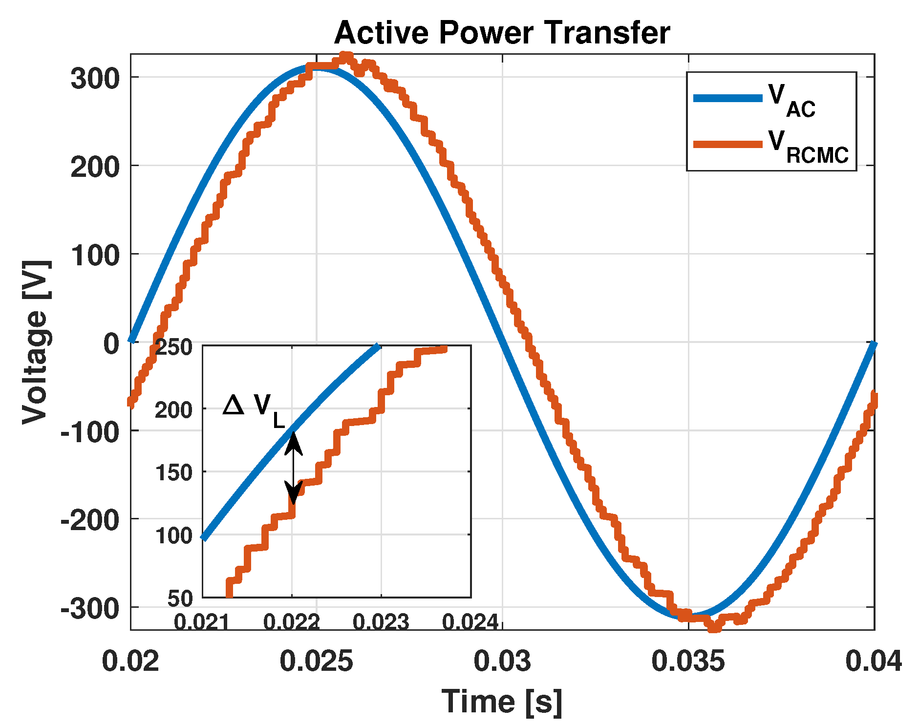
Figure 6.
SOC and battery voltages for (a) SOC balance prioritization and (b) loss reduction prioritization algorithms.
Figure 6.
SOC and battery voltages for (a) SOC balance prioritization and (b) loss reduction prioritization algorithms.

Figure 7.
(a) SOC increment trend over the insertion order. (b) Charging profile for the battery cells installed within the RCMC converter.
Figure 7.
(a) SOC increment trend over the insertion order. (b) Charging profile for the battery cells installed within the RCMC converter.

Figure 8.
(a) Experimental setup. (b) Three-phase and single-phase setups (R is the parasitic resistance of the inductor).
Figure 8.
(a) Experimental setup. (b) Three-phase and single-phase setups (R is the parasitic resistance of the inductor).

Figure 9.
Three-phase (a) current and (b) voltage. Single-phase (c) voltage and current and (d) RCMC and AC voltage. Submodule output voltages for the (e) SOC and (f) loss reduction algorithms.
Figure 9.
Three-phase (a) current and (b) voltage. Single-phase (c) voltage and current and (d) RCMC and AC voltage. Submodule output voltages for the (e) SOC and (f) loss reduction algorithms.

Figure 10.
SOC for all battery cells during loss reduction and SOC prioritization algorithms. The measurements are acquired through Matlab, using the uCube [35].
Figure 10.
SOC for all battery cells during loss reduction and SOC prioritization algorithms. The measurements are acquired through Matlab, using the uCube [35].


Table 1.
Device combination for battery selection.
| Connected Batteries | Devices Turned On | Output Voltage |
|---|---|---|
| B1 | S1, S3, S4, S6 | |
| B2 | S2, S3, S5, S6 | |
| B3 | S2, S4, S5, S7 | |
| B1 & B2 | S1, S5, S6 | 2 |
| B2 & B3 | S2, S3, S7 | |
| B1 & B3 | Prohibited | - |
| B1 & B2 & B3 | S1, S7 | |
| None | S2, S4, S6 | 0 |
Table 2.
System parameter.
| AC system | |
| Nominal peak voltage | 325 V |
| Nominal current rms | 80 A |
| Frequency | 50 Hz |
| RCMC architecture | |
| RBM per SM | 3 |
| SM per phase | 12 |
| Battery cells per phase | 108 |
| DSP frequency | 5 kHz |
| Modulation | Nearest Level Modulation |
| Nominal voltage battery module | 3.6 V |
| Nominal peak voltage per phase | 388.8 V |
Table 3.
I and II algorithm losses.
| I Algorithm | II Algorithm | |
|---|---|---|
| Initial Delta SOC 30% | 665 W | 396 W |
| Initial Delta SOC 5% | 668 W | 337 W |
Disclaimer/Publisher’s Note: The statements, opinions and data contained in all publications are solely those of the individual author(s) and contributor(s) and not of MDPI and/or the editor(s). MDPI and/or the editor(s) disclaim responsibility for any injury to people or property resulting from any ideas, methods, instructions or products referred to in the content. |
© 2024 by the authors. Licensee MDPI, Basel, Switzerland. This article is an open access article distributed under the terms and conditions of the Creative Commons Attribution (CC BY) license (https://creativecommons.org/licenses/by/4.0/).
Share and Cite
MDPI and ACS Style
Tresca, G.; Zanchetta, P. AC Direct Charging for Electric Vehicles via a Reconfigurable Cascaded Multilevel Converter. Energies 2024, 17, 2428. https://doi.org/10.3390/en17102428
AMA Style
Tresca G, Zanchetta P. AC Direct Charging for Electric Vehicles via a Reconfigurable Cascaded Multilevel Converter. Energies. 2024; 17(10):2428. https://doi.org/10.3390/en17102428
Chicago/Turabian StyleTresca, Giulia, and Pericle Zanchetta. 2024. "AC Direct Charging for Electric Vehicles via a Reconfigurable Cascaded Multilevel Converter" Energies 17, no. 10: 2428. https://doi.org/10.3390/en17102428
Note that from the first issue of 2016, this journal uses article numbers instead of page numbers. See further details here.