
Overview of Isolated Bidirectional DC–DC Converter Topology and Switching Strategies for Electric Vehicle Applications

1
College of Electrical Engineering, Qingdao University, 308 Ningxia Road, Qingdao 266000, China
2
Zhangzhou Kehua Technology Co., Ltd., Zhangzhou 363000, China
3
Department of Instrumental and Electrical Engineering, Xiamen University, Xiamen 361000, China
*
Author to whom correspondence should be addressed.
Energies 2024, 17(10), 2434; https://doi.org/10.3390/en17102434
Submission received: 16 April 2024
/
Revised: 10 May 2024
/
Accepted: 15 May 2024
/
Published: 20 May 2024
(This article belongs to the Special Issue Recent Advances in Artificial Intelligence and Computational Methods in Energy Storage Systems and Other Systems)
Abstract
:Isolated bidirectional DC–DC converters are becoming increasingly important in various applications, particularly in the electric vehicle sector, due to their ability to achieve bidirectional power flow and their safety features. This paper aims to review the switch strategies and topologies of isolated bidirectional DC–DC converters, with a specific focus on their applications in the field of electric vehicles. From the perspective of topology, PWM-type isolated bidirectional DC–DC converters, dual active bridge converters, and resonant-type isolated bidirectional DC–DC converters constitute the three main categories of these converters. The paper further examines the traditional switch strategies of these converters and discusses how specific switch technologies, such as single-phase shift, expanding-phase shift, double-phase shift, and triple-phase shift, can enhance the overall performance of isolated bidirectional DC–DC converters. The paper meticulously examines the characteristics of each topology and control scheme, as well as their typical use cases in practical applications. Particularly, the paper delves into the applications of isolated bidirectional DC–DC converters in the electric vehicle sector and draws conclusions regarding their potential and trends in future electric vehicle technology.
1. Introduction
As research into electric vehicle [1,2,3] systems deepens, the critical role of isolated bidirectional DC–DC converters (IBDCs) [4] becomes evident. IBDCs not only manage the energy exchange between the battery [5,6] and other electrical systems in the vehicle, such as converting kinetic energy into stored electrical energy during braking or providing the required energy during acceleration, but also ensure that the voltage of the battery pack matches the high voltage required by the electric motor. Furthermore, IBDCs play a core role in energy recovery, particularly during regenerative braking, where they convert electrical energy generated by the electric motor into a form suitable for battery storage. In terms of charging [7] control, they optimize the charging efficiency by adjusting the charging current and voltage while protecting the battery from the risks of overcharging or overheating. IBDCs also enhance the compatibility between electric vehicles and different charging stations and grid systems [8], improving charging flexibility. Their high energy conversion efficiency means minimal energy losses during conversion, thereby enhancing overall system energy efficiency. Their fast response characteristics ensure timely adjustments in energy supply during acceleration or braking. Research on IBDCs is crucial for driving the widespread adoption and development of electric vehicles. In addition, IBDCs are often used as key components in connecting power systems due to their excellent performance. IBDCs are widely used in smart grids [9], uninterruptible power supplies (UPSs) [10], aerospace applications, and renewable energy systems [11,12,13], such as photovoltaic (PV) arrays [14,15,16,17], fuel cells (FCs) [18,19], and other renewable energy systems [20], as shown in Figure 1.
IBDCs can match different voltage levels by adjusting the turns ratio of the primary and secondary sides of the high-frequency transformer. The turns ratio can be used as an additional degree of freedom, which broadens the regulating range of the converter, and, therefore, it is very suitable for use in applications with a large voltage gain, high safety level, and high reliability. Most IBDCs are realized by adding a transformer to the topology of a bidirectional non-isolated DC–DC converter, such as the bidirectional forward converter, bidirectional flyback converter, and bidirectional push–pull converter; while some of them are hybrid structures which are combined by various switching power supply topologies.
As shown in Figure 2, the main working principle of IBDCs is to convert the input DC voltage into AC voltage, then convert it into another voltage level of AC voltage after the high-frequency transformer, and then rectify the AC voltage into DC voltage, so as to realize DC–DC conversion. In this paper, the IBDC is divided into the PWM isolated bidirectional DC–DC converter, and DAB and bidirectional resonant converter, according to the switching strategy of the converter and the presence of the resonant cavity, among which we find the following: the PWM isolated bidirectional DC–DC converter is divided into the isolated bidirectional forward converter, isolated bidirectional flyback converter, and isolated bidirectional push–pull converter; and the DAB-type bidirectional DC–DC converter is divided into the DAB bidirectional DC–DC converter, bidirectional series resonant DC–DC converter, bidirectional parallel resonant DC–DC converter, bidirectional LLC resonant converter, bidirectional LCC resonant converter, bidirectional LCL resonant converter, bidirectional CLLC resonant converter, and bidirectional CLLLC resonant converter, as shown in Figure 3. There are interconnections between the different classifications, which will be described in detail in Section 2.
This paper is organized as follows: Section 1 is the introductory part. Section 2 describes the IBDC and its topologies and analyzes the characteristics of the topologies, including the PWM, DAB, and bidirectional resonant DC–DC converter. Section 3 describes the conventional switching strategies of the IBDC, including PWM, phase-shift control, and frequency control. Section 4 describes the application of IBDCs in electric vehicles. Finally, the conclusion of this paper is given in Section 5.
2. Topological Classification of IBDC
The IBDC can be divided into the PWM bidirectional DC–DC converter, DAB DC–DC converter, and bidirectional resonant DC–DC converter. The working principle of a bidirectional isolated DC–DC converter topology is basically to convert the input DC voltage into AC voltage, which is then rectified into DC voltage through the transformer. The classification and summary of these topological structures are as follows.
2.1. PWM-Type Isolated Bidirectional DC–DC Converter Topology
2.1.1. Bidirectional Forward Converter
As shown in the Figure 4, the bidirectional forward converter [21] has a simple structure and is easy to control and is mostly used in small- and medium-sized power situations. As illustrated in Figure 4, the circuit employs three switching tubes, labeled as S1, S2, and S3. The isolation forward transformer, indicated by T, serves to electrically isolate the primary and secondary sides of the circuit, enhancing the safety and performance. The energy storage inductor, denoted by L, plays a critical role in maintaining the energy integrity throughout the switching cycles. For the purpose of voltage smoothing, filtering capacitors C1 and C2 are strategically placed within the circuit. V1 and V2 are the input and output voltages, respectively. However, the transformer always operates in the unidirectional excitation mode, which has a low utilization rate, and requires another magnetic reset winding to work normally, which is more difficult to design [22].
In order to solve the magnetic reset problem of the isolated bidirectional forward converter, the existing solutions are mainly to combine the forward converter with other converters, so that the advantages and disadvantages of different converters can be complementary. A forward–flyback bidirectional DC–DC converter has been proposed to combine the forward converter and the flyback converter, which solves the problem of the unidirectional excitation of the forward converter, as well as the problem that the switch of the flyback converter has voltage spikes [23]. Another converter consists of two identical forward switching converters combined by a shared transformer; this structure reduces the number of switching tubes and saves cost while solving the problem of the forward converter itself [24]. A new PWM ZVS bidirectional forward DC–DC converter has been proposed. It uses the transformer’s leakage inductance for power transfer, allowing it to reset the PWM-controlled transformer core and satisfy the ZVS soft switching condition. The proposed converter is also inexpensive and straightforward [25].
In general, the development trend of the forward converter is as follows: high efficiency and high reliability. In the development of the forward converter, there are many efficiency improvements, and, with the progress of the integrated circuit process and passive component process, the integration of the forward converter will be higher, while its efficiency and reliability will continue to improve, along with having a smaller size, higher frequency, and modularity. In the forward converter, the transformer plays the role of energy transfer, with the switching frequency and passive components manufacturing process improvements, and the volume of the transformer and the volume of the vice side filtering inductance; the capacitance can also be greatly reduced, thus reducing the volume of the entire switching power supply.
2.1.2. Bidirectional Flyback Converter
Figure 5 shows a bidirectional flyback DC–DC converter, which is also suitable for low power applications. In Figure 5, the switching devices S1 and S2 are strategically positioned to regulate the current within the circuit. The isolation flyback transformer, denoted as T, ensures the electrical separation between the primary and secondary sides. The capacitors C1 and C2 are integrated to smooth out the voltage ripple, functioning as filtering components within the system. V1 and V2 are the input and output voltages, respectively. The flyback converter has many advantages such as a simple circuit topology, few electronic components, low cost, easy control, high safety of input or output galvanic isolation, and good output voltage or current characteristics. The output can be designed in boost or buck mode, featuring a wide regulation range and easy implementation of multi-output designs. Compared to other switching power supply circuits, its energy efficiency is low, but its simple topology and low cost make it the preferred choice for low-power applications.
In addition to this, the switching tube is subjected to high current stresses and voltage stresses and due to the presence of leakage inductance of the transformer, which causes the energy on the leakage inductance to resonate with the output capacitance of the switching tube, thus generating voltage spikes, which may damage the switching tube [26]. An active clamped bidirectional flyback converter was investigated to derive a low-frequency behavioral model and a small signal transfer function; the current flow of this converter is directly controlled by the duty cycle, and the leakage inductance of the transformer has a significant effect on the control characteristics of the converter [27]. A sub-module level isolated port differential power processing architecture based on the bidirectional flyback converter has been proposed to improve efficiency. The bidirectional flyback converter is designed as a sub-module with discontinuous conditional modes and continuous conditional modeling modes for light and heavy load conditions to improve efficiency [28]. A new isolated bidirectional two-tube flyback converter is proposed which integrates two non-dissipative inductive capacitive diode buffers. In the suggested architecture, in addition to recovering the leakage energy and shielding the power transistors from circulating currents that would arise in the non-cross-coupled scenario, the primary inverting transformer and the inductive–capacitive diode buffers are cross-coupled. In a bidirectional flyback converter with a traditional resistor–capacitor–diode buffer, the same current cycling issue arises. Additionally, a different circuit is suggested to reduce current cycling and boost conversion efficiency [29].
Nowadays, the development trend of industrial flyback switching power supply is mainly to improve the accuracy, miniaturization, and conversion efficiency, and, because the power supply belongs to a kind of energy, it is developed towards renewable energy.
2.1.3. Bidirectional Push–Pull Converter
Figure 6 shows a bidirectional push–pull DC–DC converter [30], which has an increased power rating but also a further increase in voltage and current stress on the switching tubes compared to the two forward and flyback transformers mentioned above, for applications in low-voltage and medium-voltage high-power situations. As depicted in Figure 6, the switching transistors S1, S2, S3, and S4 are responsible for modulating the current within the push–pull converter’s circuit. The transformer’s primary coil is configured with a total of Np1 and Np2 winding turns, whereas the secondary coil features Ns1 and Ns2 turns. The inductor L serves as the energy-storing component within the converter’s design. C1 and C2 are the filtering capacitors. The converter operates between an input voltage V1 and provides an output voltage V2. The bidirectional push–pull converter, in which both the primary and secondary sides of the transformer are of a push–pull structure, operates in a bidirectional excitation mode with a significantly higher transformer utilization, and is suitable for higher power ratings than the bidirectional forward and flyback converter, but still suffers from the problem of resonance voltage spikes due to leakage inductance, which restricts its operation to higher power ratings [31,32].
To reduce the amount of switching transistors and the gate drive components that go with them, a new converter is presented. A higher efficiency can be achieved by using a phase-shifting control strategy where all switching tubes are operated under zero-voltage switching conditions [24]. A bidirectional current-type three-phase push–pull DC–DC converter for DC microgrids is highlighted, and a new modulation technique is suggested that addresses the issue of voltage spikes created during the clamping of the current-type devices and allows for soft switching. The three-phase structure can improve the efficiency of the converter [33]. A new triple anti-excitation current-fed push–pull bidirectional DC–DC converter is proposed, and the working principle of the proposed converter is analyzed and explained from two aspects, where DC transfer functions are presented for the continuous, discontinuous, and critical conduction modes [34]. A bidirectional push–pull DC–DC converter topology with current isolation has been proposed to realize the wide range of the converter. This topology achieves the full soft switching of all transistors over a wide input voltage and power range without the need for resonant switches or snubbers [35].
The PWM-type isolated bidirectional DC–DC converter topology has the advantages of having fewer electronic devices, being easy to control, being able to basically meet the needs of small and medium power, and having push–pull converter power, although the power can be slightly improved, but, in the high-power occasions, it still seems a little insufficient. A comparison of several PWM-type isolated bidirectional DC–DC converter topologies is shown in Table 1.
2.2. Dual Active Bridge DC–DC Converter Topology
The topology of the dual active bridge (DAB) DC–DC converter is shown in Figure 7. In Figure 7, V1 signifies the input voltage, while V2 represents the output voltage. The filtering capacitors, denoted by C1 and C2, are integral for smoothing the output voltage waveform, thereby reducing ripple and enhancing the quality of the power supplied to the load. On the primary side, the inverter switching devices S1, S2, S3, and S4 are responsible for modulating the current flow through the energy transfer inductor L, which is critical for energy storage and transfer across the converter. On the secondary side, the rectifier switching devices S5, S6, S7, and S8 are tasked with converting the AC back into DC, ensuring the efficient energy transfer to the load side. The high-frequency isolation transformer, designated as T, provides electrical isolation between the primary and secondary sides, which is essential for safety and can also help in voltage matching and noise reduction. This topology was proposed by Prof. De Doncker in 1988 [36], but, due to the limitations of the power devices at that time, which resulted in low efficiency, this topology did not attract much attention [37]. In 2007, Prof. Yasufumi Akagi proposed that the DAB converter can be used as the core topology of the next-generation high-frequency isolation converter, and, with the development of switching devices, the DAB converter has gradually been emphasized by more scholars [38]. The DAB converter is made up of full-bridge circuits on both sides, an auxiliary inductor, and a high-frequency transformer. Because of the full-bridge circuit construction on both sides, power can flow in both directions and active control is possible on both sides [39,40]. The number of switching tubes is twice as much, the converter’s transferred power capacity is greater, and the voltage–current stress on the switching devices is half that of a bidirectional half-bridge converter. DAB converters are widely utilized in numerous developing applications, like vehicle-to-grid systems, in addition to energy storage systems [41] and solid-state transformers [42]. The benefits of DAB converters’ high-power density, current isolation, soft-switching capabilities, and adaptability to different power modulation schemes are what make them appealing. The fundamental method of power control in a traditional DAB converter involves applying two phase-shifted high-frequency AC voltages (square or quasi-square) to the ends of the energy-transferring inductors via an H-bridge. This allows energy to move from the overrunning AC voltage to the lagging AC voltage [43]. In addition, DAB converters are characterized by a symmetrical topology, high power density, and easy soft switching, and are widely used in DC distribution grids, electric vehicles, power electronic transformers, distributed power generation systems, and other fields.
The characteristics of the DAB converter are shown in Table 2. The DAB-IBDC has drawn increasing interest in recent years because to its benefits, which include the easy implementation of soft switching, bidirectional power transfer capability, modular symmetrical structure, etc. The two full-bridge converters, two DC capacitors, an auxiliary inductor, and a high-frequency transformer comprise the topology of the DAB-IBDC. The necessary voltage matching and current isolation between the two voltage levels are supplied by the high-frequency transformer. An additional inductor is employed as a temporary energy storage mechanism. Research on the DAB-IBDC has so far concentrated on the following topics: hardware design and optimization, soft-switching methods and variants, control strategies, and fundamental features.
2.3. Resonant Isolated Bidirectional DC–DC Converter Topology
The bidirectional resonant converter is a special type of IBDC, and it is also one of the topologies that can achieve bidirectional energy conversion. This type of converter is usually applied to systems with a bidirectional energy flow, such as electric vehicle charging piles, renewable energy systems (e.g., wind and solar energy systems), grid energy storage systems, and so on. The basic working principle of the bidirectional resonant converter is to realize the conversion of the input electric energy in a resonant state by means of reasonably designed inductive and capacitive components. One of the characteristics of the bidirectional resonant converter is the ability to achieve high-efficiency bidirectional energy conversion as shown in Figure 8 with a low level of electromagnetic interference. The development of bidirectional resonant converters has been driven by the needs of electric vehicles, renewable energy, and grid intelligence, and its performance and application range have been expanded and improved with the continuous progress of power semiconductor devices and control technologies. Therefore, as an important energy conversion technology, the bidirectional resonant converter has a broad application prospect in the field of energy and power electronics. Common bidirectional resonant converter topologies include the bidirectional series resonant converter, bidirectional parallel resonant converter, bidirectional LLC resonant converter, bidirectional LCC resonant converter, bidirectional LCL resonant converter, bidirectional CLLC resonant converter, bidirectional CLLLC resonant converter, and so on.
2.3.1. Bidirectional Series Resonance Converter
The bidirectional series resonant converter is based on the traditional bidirectional full-bridge DC–DC converter and introduces LC series resonance on the primary side of the converter, and the topology of the converter is shown in Figure 9; the resonant inductor L can be set separately.
In order to prevent transformer saturation brought on by the switching devices’ volt–second imbalance, the resonant capacitor C can also function as an isolation capacitor. This allows it to effectively separate the DC component of the resonant current. Due to the low probability of saturation of the series capacitor DBSRC transformer, the disadvantage of the DBSRC is the size of the resonant loop, which brings additional size and cost. However, this converter can only operate in buck mode and cannot achieve boost; there is a maximum voltage gain when the converter operates at the resonant frequency, but the output voltage regulation characteristics of this converter are not ideal for application in scenarios where the output voltage regulation range is large. A technique for the optimal design of a series resonant converter based on a frequency domain analysis is proposed to analyze the ZVS and ZCS operations in the bidirectional power transfer process and to describe in detail the working principle of the converter in order to improve the efficiency of the entire system. Resonant loop current minimization in the isolated resonant converter is a matter of interest [44].
2.3.2. Bidirectional Parallel Resonance Converter
There is less power loss in the switching tubes and less ripple in the output current of the bidirectional parallel resonant converter. Without sacrificing ZVS conditions, the conversion employs forced switching across a preset frequency range or self-excited oscillatory switching approaches. High voltage ratios between ports are made possible by the high-frequency transformer, which makes converters useful for a variety of energy storage systems, including hybrid cars, that need to be able to transfer power in both directions. LC parallel structures, on the other hand, are shown in the figure, where a resonant inductor is connected in series with a capacitor in the resonant cavity, and the transformer’s primary side is subsequently connected to the two ends of the resonant capacitor to form a parallel relationship. The LC parallel resonant structure has large output current fluctuations and is prone to energy circulation between the resonant capacitor and the equivalent load, so parallel resonance is not common. As application requirements increase, simple series or parallel structures are no longer suitable for some applications, and more complex and variable resonant structures have been created. Figure 10 depicts the circuit structure of the shunt resonant converter, which also has an inductor L and a capacitor C connected in series to form a resonant network. The shunt resonant converter differs from the traditional series resonant converter in that the resonant capacitor and the primary side of the transformer are in parallel, and an inductive element must be added to the vice side of the transformer in order to match the impedance, and the output of the rectifier network is filtered by the filtering inductance and the filtering capacitors, and then the energy will be transferred to the load side. The output of the rectifier network is filtered by the filter inductor and filter capacitor to transfer the energy to the load. The advantages of the shunt resonant converter are as follows: in the operating frequency range greater than the resonant frequency, it can realize the ZVS of the primary switching tube, and, compared with the series resonant converter, its adjustment range is wider; in the case of a light load, the output voltage is very sensitive to the change in operating frequency; when the output voltage fluctuation occurs, it is only necessary to increase the switching frequency accordingly to make it stable again.
At the same time, the parallel resonant converter also has the following disadvantages: when the load is zero, due to the parallel resonant converter resonant capacitor and the load being a parallel structure, at this time, it is equivalent to the case where only the resonant element is working; the impedance is very small, resulting in the switching-off of the current and a loop energy rise; switching losses increase; the efficiency decreases; the resonant slot current is not affected by the load; and the circuit’s pass-state loss is basically unchanged, so the efficiency of a light load is very low. A very low load, mostly used for a relatively constant load and output voltage range of narrower occasions, due to the increase in the output side of the converter filter inductor, will not be conducive to improving the power density of the switching power supply.
It was suggested to use a resonant push–pull inverter in parallel with a multi-output bidirectional DC–DC converter in series with a high-frequency current source to control load variations. Alternatively, a straightforward photovoltaic power generation system with a bidirectional converter and a current-fed inverter was suggested [45]. A low-current-ripple, high-voltage-gain shunt resonant isolated bidirectional DC–DC converter for a battery storage system was proposed in order to increase efficiency. It makes use of a transformer shunt resonant capacitor to achieve the soft switching operation and recover the leakage inductance energy [46].
2.3.3. Bidirectional LCC Resonant Converter
The LCC resonant converter combines the advantages of both the parallel resonant converter and series resonant converter [47]. Therefore, it is also often called the LCC resonant converter [48,49]. The typical topology of an LCC resonant converter is shown in Figure 11. One possible application for the transformer’s leakage inductance is in the series resonant inductance or in the inductance of the LCC converter, and the shunt parasitic capacitance of the transformer can be used as a part of the shunt resonant capacitance or part of the shunt resonant capacitance, which further reduces the circuit components.
Since the 1980s, researchers have paid attention to the above characteristics of LCC resonant converters and have conducted a lot of studies [50,51,52], giving a series of analysis, design methods, and application methods. Among them, the high-voltage DC power supply has become a very important application of the LCC converter. High-voltage DC power supplies usually need to convert input voltages of tens or hundreds of volts into output voltages of tens or even hundreds of kilovolts. This must be a high-turns-ratio high-voltage transformer to meet the boosting demand, and, in order to increase the power supply’s safety, simultaneously rely on the transformer to offer the primary and secondary isolation of the high-voltage side and low-voltage side. The transformer has a large parallel parasitic capacitance due to the high turns ratio [53] and high voltage isolation requirements on the primary and secondary sides result in a substantial leakage inductance [54,55]. The leakage inductance can be part of the series resonant inductance of the LCC transformer, the shunt parasitic capacitance can be part of the shunt resonant capacitance, and the parasitic parameters of the high voltage transformer do not negatively affect the LCC transformer. Conversely, the substantial shunt parasitic capacitance of the LLC transformer makes it more likely to become a fourth-order resonant transformer, which is undesired in real-world applications. Therefore, the LCC resonant converter has more obvious advantages over the LLC converter in the application of a high-voltage DC converter. The LCC converter can utilize the above-mentioned transformer parasitic parameters as resonant elements, and also has the advantages of soft switching and a wide input–output range [56].
2.3.4. Bidirectional LCL Resonant Converter
As seen in Figure 12, the bidirectional LCL resonant converter substitutes an LCL resonant network for the DAB converter inductor L. The return power can be eliminated by controlling the voltage and current on both sides of the resonant network to be in the same phase when the operating frequency of the converter is the same as the resonant frequency. It is suggested to utilize an isolated three-port bidirectional DC–DC converter to control several energy sources at once. The advantages of this converter are the use of a minimum number of switches and the possibility of soft switching, which is achieved by using an LCL resonant circuit. The proposed converter is constructed to manage PV panels, rechargeable batteries, and loads simultaneously [57]. In order to improve the efficiency of the converter and reduce losses, a single-stage isolated bidirectional DC–DC converter for general-purpose electric vehicle charging has been proposed, that includes an LCL resonant network, which uses a fixed-frequency phase-shift control that allows for the simple design of passive components and soft switching of all the transistors in constant-current, constant-power, and constant-voltage charging modes, with a minimum of circulating current [58].
In addition, the LCL-DAB converter is a common converter. The relationship between the current harmonics and returned power when the converter is modulated by TPS modulation is analyzed, and it is pointed out that the smaller the current harmonics are, the smaller the returned power is. However, this paper only analyzes the qualitative relationship between them and does not give a specific quantitative relationship [59]. Another multilevel LCL-DAB converter topology has been proposed with a four-level modulation method, which effectively improves the efficiency of the converter at light loads [60].
2.3.5. Bidirectional LLC Resonant Converter
In order to solve the problem of the high DAB converter turn-off loss and low system efficiency, scholars have introduced resonant units in isolated DC–DC topologies. The bidirectional LLC topology shown in Figure 13 is a typical application. The resonant capacitor is added on the basis of the DAB converter, and the resonant inductor resonates with the resonant capacitor, which makes the resonant cavity current waveform present sinusoidal characteristics, which can realize the zero-current switching-off of the switching tube through the resonant current over zero, and also reduce the distortion of the transformer waveform and reduce its eddy current loss. The structure of the LLC is similar to that of the series resonant converter, and both of them change the resonant cavity impedance by adjusting the switching frequency, thus adjusting the gain of the converter. Compared with SRC, the bidirectional LLC resonant converter can realize an equivalent gain greater than 1, which broadens the system gain range, but, due to the asymmetry of the LLC structure, when working in reverse mode, its structure is the same as that of SRC, and it can only realize the buck voltage.
A bidirectional control strategy for the LLC-LC type of LLC resonant converter has been proposed, which automatically realizes the bidirectional tidal currents without any current detection procedure and always guarantees soft switching. Using the proposed control strategy improves the starting characteristics under no-load conditions and avoids the risk of an output voltage rise and current surges [61]. A bidirectional LLC-DCX converter with a center-tapped transformer has been given a better topology and PWM in order to prevent voltage spikes and increase efficiency. This converter uses a modulation strategy that enables ZVS on both the auxiliary and LV side power switching tubes in order to lower the EMI and switching losses [62]. Another scheme to realize an efficient stand-alone PV system is investigated, which is achieved by sharing resonant capacitors to regulate the equivalent resonance conditions of the two phase-controlled resonant loops. The novel circuit improves the overall efficiency without increasing the cost of the power components by improving the LLC converter for a fixed-frequency operation and reducing the number of power conversion stages simultaneously [63].
LLC converters are often used in conjunction with DAB converters. LLC resonant converters and DAB converters are attractive topologies for bidirectional power applications due to their respective advantages; here are some examples: An LLC-DAB bidirectional converter is proposed with a reduced number of switches where eight main switching tubes are used for full-load-range ZVS, four auxiliary switching tubes are used for wide-load-range ZVS, and switching junction capacitance for different power directions is considered. An additional DAB circuit receives a fraction of the total power for the purposes of bidirectional power conversion and voltage regulation. The main power is transferred through an LLC circuit for high conversion efficiency and to achieve ZVS without a synchronous rectifier circuit for switching tubes [64]. In order to realize bidirectional power and high efficiency, an auxiliary DAB converter operating at a fixed frequency and a bidirectional LLC converter with an input-series-output-parallel structure are combined. A new scheme based on a full-load-range instantaneous transfer power estimation for accurate synchronous rectification is proposed to achieve the on-line synchronous rectification modulation of LLC-DCX for bidirectional power applications, which employs an additional auxiliary DAB converter as a power detector to estimate the power value [65]. To integrate the DAB and LLC converters into a single converter based on modulated coupled inductors, a dual-mode bidirectional LLC-DAB converter was proposed. The converter’s LC energy storage circuit can be altered in both working modes by simply modulating the PWM signal. It is appropriate for resonating in the LLC mode with a resonant capacitor due to its small leakage inductance [66].
2.3.6. Bidirectional CLLC Resonant Converter
To improve the voltage regulation and soft-switching problems of the bidirectional LLC resonant converter in reverse operation, a resonant capacitor Cr2 can be added to the secondary side of the bidirectional LLC resonant converter to form a bidirectional CLLC resonant converter, as shown in Figure 14 [67]. This topology allows the circuit to realize soft switching over the full load range with good voltage regulation regardless of forward or reverse operation [68,69]. The problem of this structure is the asymmetry between the primary and secondary sides of the converter, which results in different resonant slots for the forward and reverse operation of the converter, and thus different resonant frequency characteristics and gain characteristics, which makes the parameter design, as well as the control of the circuit, more difficult. Another bidirectional CLLC resonant converter has a symmetrical structure, as shown in Figure 15; this topology can solve the problem of asymmetric power transfer characteristics in the forward and reverse directions, but there are still some drawbacks in the frequency conversion control, because the frequency conversion control of the resonant converter is to adjust the equivalent impedance of the resonance cavity to realize the voltage matching at the output. In other words, when the output load changes, the operating frequency of the converter will also change, which results in the dynamic characteristics of the converter being affected. At the same time, in a wide voltage range of occasions, the converter frequency range will be correspondingly wide, which is not conducive to the improvement of efficiency and the design of converter parameters.
This resonant structure has been proposed in order to realize a wide voltage range regulation under bidirectional transmission, as well as to easily achieve soft switching and a high efficiency [70]. The literature [71] gives another CLLC resonant structure, where a resonant capacitor Cr2 is added to the secondary side of the transformer on the basis of the LLC resonant structure, constituting an asymmetric CLLC structure, which also solves the problem of the inverse gain being less than one. From the analysis, it can be seen that both symmetric and asymmetric CLLC structures can solve the problem of a low inverse gain, but, due to the addition of an extra resonant element, it brings about the problems of increased size, design difficulty, and reduced power density. The CLLC design method based on parametric equivalence and time-domain modeling has been proposed to design CLLC resonant tank parameters with arbitrary parameters, but it increases the complexity of modeling and analysis [72].
A bidirectional CLLC resonant converter with a quadratic resonant slot is described, as shown in Figure 15, which improves on the topology of the above converter by adding a resonant capacitor Cr2 to the secondary side of the converter, which constitutes different resonant networks due to the different resonant elements in forward and reverse operation, and both the primary and secondary switching tubes are capable of achieving soft switching, so that the converter can be operated in both the forward and reverse directions; both have a higher efficiency when operating in forward and reverse, and can realize the boost/boost function. However, the structure of the converter is asymmetric in the forward and reverse operation, which makes the converter have different operating characteristics in the forward and reverse operation and increases the complexity of designing the relevant parameters of the converter and the difficulty of control [73]. In order to improve the efficiency and power density, an integrated transformer bidirectional CLLC converter with synchronous rectification has been proposed, which can be used for plug-in electric vehicles, using an integrated transformer and simulated using finite element analysis, and synchronous rectification has also been achieved [74]. For this converter, an optimized adjustable leakage inductance planar transformer based on stacked printed circuit board windings was constructed and designed to achieve a high power density and high efficiency [75].
2.3.7. Bidirectional CLLLC Resonant Converter
The bidirectional CLLLC resonant converter topology has good soft-switching characteristics and can realize structurally symmetric bidirectional energy flow, which has been recognized by scholars, and much research has been conducted on this. In terms of application, the CLLLC resonant converter structure is applied to energy storage converters, which improves the energy utilization efficiency and power quality [76]; this topology is applied to power electronic transformers to realize soft switching, and the immunity performance of the voltage loop and voltage equalization loop and the power equalization control are verified to be effective from the parameter design point of view [77]; in order to simplify the circuit design, an equivalent model of the CLLLC resonant converter is established using a fundamental analysis, and the converter zero-voltage on-state, voltage gain, and transmission efficiency are used as the constraints on the parameter selection [78]; in view of the problem of the CLLLC resonant converter with a large frequency adjustment range and a small voltage gain range, we used a hybrid boost control strategy [79]; a frequency-shift hybrid control method was presented to address the low phase-shift modulation efficiency and short voltage gain range of the CLLLC resonant converter. This method allows for the simultaneous modification of the switching frequency and switching duty ratio [80]; moreover, in order to improve the efficiency of the CLLLC resonant converter, a new broadband semiconductor device GaN-HEMT was used [81]; the three-phase interleaved parallel bidirectional transmission CLLLC resonant converter has been researched in order to reduce the converter power size [82].
The topology of the CLLLC resonant converter is shown in Figure 16. Compared with the LLC resonant converter shown in Figure 13, this symmetrical structure adds an LC resonant network to the secondary side of the transformer. In forward operation, the excitation inductance Lm of the transformer is equated to the primary side, as shown in Figure 16, which forms an LLC resonant network with Lr1 and Cr1; when the converter operates in reverse, Lm can be equated to the secondary side, which forms an LLC resonant network with Lr2 and Cr2. In fact, the excitation inductor is in the middle of the transformer and should be in the middle of the two LC resonant networks, so the structure shown in Figure 16 is completely symmetrical. Inductors Lr1, Lr2, and Lm and capacitors Cr1 and Cr2 combine to form a CLLLC resonant network.
The symmetric CLLLC resonant converter topology shown in Figure 16 has been studied in several papers [38,83,84], but some of them consider it as a bidirectional SRC structure without considering the excitation inductance. The studied structure, although formally symmetric, requires the switching of the resonant capacitors in different operating directions, and the added bidirectional switching increases the complexity and cost of the structure [85]; Wen wrote a gain expression for the resonant network, which, in turn, yields several key resonant frequency points. On this basis, the peak voltage gain equation of the symmetric CLLLC resonant converter is derived, and a simplified design method is proposed based on this equation, which avoids the complex solution and lengthy simulation process [86]; the symmetric structure of the CLLLC resonant converter is studied in detail in terms of the operating principle, operating characteristics, design method, and control method [87].
However, the above literature assumes that the parameters of the resonant network in the converter are also symmetric in the analytical process and does not consider the effect of parameter asymmetry on the converter, while, in reality, there is always a slight asymmetry in the parameters due to component errors and other reasons. Meanwhile, the actual operating characteristics of the CLLLC resonant converter, such as the gain characteristics, soft switching characteristics, light load characteristics, and starting characteristics, are still to be studied in depth.
Although the increased resonant inductor capacitance on the secondary side of the symmetrical CLLLC resonant converter affects the fundamental characteristics of the entire resonant network, this converter is still the structure with a performance closest to that of the LLC resonant converter and is able to maintain a high degree of consistency in the bidirectional operation, which is an obvious advantage as a topology for high-power IBDCs.
A comparison of several bidirectional resonant converter topologies is shown in Table 3.
3. Switching Strategies
In the switch control strategy of IBDC, it mainly includes PWM control, phase-shift control, and frequency control. PWM control is primarily applied in PWM bidirectional DC–DC converters within IBDCs, while phase-shift control and frequency control are mainly used in DAB converters and bidirectional resonant converters. Therefore, in the following text, PWM control is introduced for each type of PWM bidirectional DC–DC converter, and phase-shift control and frequency control are discussed in the context of the DAB converters and bidirectional resonant converters.
3.1. PWM Control
The PWM modulation strategy is adjusted by adjusting the duty cycle of the switching tubes, as shown in Figure 17 for the basic PWM modulation strategy. This modulation strategy is mostly used in circuits with a PWM bidirectional DC–DC converter structure and is used less in resonant circuits because it is difficult to realize soft switching of the switching tube when the duty cycle adjustment range is large [88,89,90]. In terms of PWM switch strategies applied to bidirectional forward converters, as shown in Figure 17a, switches S1 and S2 are simultaneously turned on and off, while switch S3 and the driving waveforms of S1 and S2 are complementary. By adjusting the pulse widths of S1 and S2, control of the output voltage can be achieved, with the same switch strategies applied for both the forward and reverse directions. For bidirectional flyback converters, the switch strategy is simpler. As depicted in Figure 17b, the driving signals for switches S1 and S2 are 180° out of phase, and, similarly, control of the output voltage is achieved by adjusting the pulse widths of S1 and S2. The switch strategy for bidirectional push–pull converters is slightly more complex, as shown in Figure 17c. Different driving signals are applied to switches S1, S2, S3, and S4. When operating in the forward direction, the driving signals for switches S1 and S2 on the primary side of the transformer are 180° out of phase, while switches S3 and S4 on the secondary side of the transformer are complementarily conductive. Control of the output voltage is achieved by adjusting the pulse widths of switches S1 and S2. Conversely, when operating in the reverse direction, the situation is reversed. The driving signals for switches S3 and S4 on the secondary side of the transformer are 180° out of phase, while switches S1 and S2 on the primary side of the transformer are complementarily conductive. Control of the output voltage is achieved by adjusting the pulse widths of switches S3 and S4. vT1 refers to the primary voltage of the transformer.
3.2. Phase-Shift Control
Phase-shift control is the most commonly used switch strategy in DAB converters and bidirectional resonant converters, as illustrated in Figure 18. By controlling the phase-shift angle, it regulates the output voltage and current, making it highly suitable for scenarios involving a bidirectional power flow. There are four commonly used phase-shift modulation strategies, namely, SPS, EPS, DPS, TPS.
3.2.1. Single-Phase Shift
SPS is the most classical phase-shift modulation method in the DAB converter and bidirectional resonant converter, and the key waveforms under SPS modulation are shown in Figure 19, where vAB is the AC voltage at the primary side of the transformer, vCD is the AC voltage at the secondary side of the transformer, and iL is the current flowing through the equivalent inductor L. As shown in Figure 16, the equivalent inductor L represents the leakage inductance Lm of transformer T and the external series inductance Lr, and the turns ratio is n:1. Ts denotes the switching period, and Th denotes half of the switching period. In a typical phase-shift modulation method, two power switching tubes in the same bridge arm should conduct complementarily with a 50% duty cycle.
SPS modulation produces a square-wave AC voltage with a 50% duty cycle on both the main and secondary sides of the transformer by sequentially and simultaneously switching the cross-connected switches in the two complete bridges. As a result, the phase shift D between the primary and secondary sides of the transformer can be changed to change the voltage across the equivalent inductor L. This means that the transferred power and the associated steady-state performance of the DAB converter and bidirectional resonant converter can be easily controlled. Moreover, only when the input and output side voltages are matched can the DC–DC converter benefit from the SPS modulation method, which also allows for a broader soft-switching range, lower current stress, and improved transfer efficiency. If not, it can result in a narrower zero-voltage switching range, higher loop currents, root-mean-square currents, and current stresses [91,92,93]. Therefore, when the input and output voltages are mismatched, the transfer efficiency of the DC–DC converter will be greatly affected, especially under light load conditions.
3.2.2. Expanding-Phase Shift
Figure 20 displays the main waveforms of the EPS modulation strategy, which is a common way to improve the SPS modulation strategy. As illustrated in Figure 20, the external phase-shift angle is DE2, and an extra internal phase-shift angle DE1 is added to either the primary or secondary side, in contrast to the SPS modulation technique. Consequently, in the EPS modulation strategy, the full bridge’s one side produces a three-level AC voltage, but, in the SPS modulation strategy, the full bridge’s other side produces a two-level AC voltage with a 50% duty cycle. When EPS modulation is used instead of SPS modulation, it not only increases the transmission efficiency but also expands ZVS’s operational range, lowers reactive power, lowers current stress, and increases regulatory flexibility [94,95].
3.2.3. Double-Phase Shift
The key waveform of the DPS modulation strategy, which is comparable to the EPS modulation strategy, is depicted in Figure 21. It features one exterior phase-shift angle DD2, and two internal phase-shift angles of equal value DD1. As shown in Figure 21, the DPS modulation strategy usually contains two different operating modes, i.e., 0 < DD1 < DD2 < 1 and 0 < DD2 < DD1 < 1.
The operating principle, transmitted power, current stress, power loss, and soft switching, as well as the optimization design methodology of DPS modulation, are discussed in the references [42,96,97,98]. The DPS modulation approach, like the EPS modulation strategy, can be utilized to improve the ZVS working range, lower reactive power, lower current stress, and increase transmission efficiency in order to improve the steady-state performance of DAB converters and bidirectional resonant DC–DC converters.
Since the input and output full bridges of the DPS modulation strategy have the same internal phase-shift angle of DD1, when the converter shifts between the buck and boost modes, or when the direction of power transfer changes, there is no need to modify the working states of the two full bridges. The DPS modulation approach is simpler to implement than the EPS modulation strategy.
3.2.4. Triple-Phase Shift
Figure 22 displays the main waveforms of the TPS modulation technique. The TPS modulation method is similar to the DPS modulation strategy in that it features two independently controlled internal phase-shift angles (D1 and D2) at the secondary-side full bridge and the primary-side full bridge, respectively, as well as an exterior phase shift angle D3. Therefore, the TPS modulation contains three optimized control quantities (D1, D2, and D3) that can be controlled independently, which makes the TPS the most flexible phase-shift modulation strategy compared to the SPS modulation, the EPS modulation, and the DPS modulation. Therefore, the TPS modulation strategy has the greatest potential for performance optimization when compared to the other three phase-shift modulation strategies. The operating principle, transmitted power, current stress, power loss, and soft switching, and optimized design methodology of TPS modulation are discussed in the references. The TPS modulation strategy enables the converter to achieve the minimum current stress, minimum rms current, minimum power loss, and maximum ZVS range, etc., compared to the other three phase-shift modulation strategies [99,100,101,102].
Special cases of TPS modulation include SPS modulation, EPS modulation, and DPS modulation. The relationship between these four types of phase-shifted modulation is shown in Figure 22. TPS modulation can be classified as either SPS or EPS depending on whether D1 = D2 = 1 or D1 = 1; when D1 = D2, it can be classified as DPS modulation.
3.3. Variable Frequency Control
In addition to phase-shifted modulation strategies, frequency modulation strategies have also become a popular method for optimizing the modulation of the DAB converter and bidirectional resonant DC–DC converter, especially for wide-range power transmission. A higher power transfer is possible with a lower switching frequency in a resonant DC–DC converter and vice versa. Figure 23, where Tss, Tms, and Tls denote the high-, medium-, and low-frequency cases, respectively, displays the main waveforms of the SPS modulation method at various switching frequencies. From Figure 23, it can be seen that, for the same phase-shift angle D, a lower switching frequency can realize a larger inductor current and transferred power.
Variable frequency modulation is often combined with phase-shift modulation methods to optimize the DAB converter and bidirectional resonant DC–DC converter. For example, reference [80] proposes a variable-frequency phase-shifting scheme to reduce the reactive power of a DC–DC converter while extending the ZVS range. Furthermore, four optimization degrees of freedom may be achieved by combining TPS with inverter modulation, which offers a significant deal of opportunity to further enhance the converter’s steady-state performance and transmission efficiency [103]. This modulation strategy with four optimization degrees of freedom puts higher demands on the solution technique.
4. Application of IBDC in EV
The IBDC is widely used in the energy management system of EVs to achieve the efficient energy conversion and transmission mentioned in the overview [104]. Firstly, it converts the DC from the battery pack into DC suitable for driving the motor, ensuring effective energy utilization and management. Secondly, it plays a crucial role in the charging system of EVs by converting the DC from external power sources (such as charging stations) into the voltage and current characteristics required by the battery pack, facilitating fast and safe charging processes. Additionally, the IBDC is employed in the auxiliary power system of EVs, supplying power to onboard electronic devices, and controlling auxiliary function modules. Its high-efficiency energy conversion capabilities guarantee a stable operation and efficient energy utilization across various vehicle systems. Overall, the IBDC significantly contributes to the efficient, safe, and reliable operation of electric vehicles, thereby driving advancements and developments in EV technology. Here are a few examples.
4.1. IBDC in EV
In order to obtain reference values of inductors in simulation studies of power inductors in DC–DC converters, experimental schemes and methods for power inductors in EV applications with large-signal characteristics have been proposed and the use of DC flux canceling techniques in bidirectional converters and the use of variable inductance prototypes instead of power inductors in order to adapt to the space requirements of the EV, and the reduction in core sizes by increasing the ripple content of inductance currents, have been applied to the EV. The optimization of the power inductor core size in bidirectional DC–DC converters was investigated [105].
In the review [106], the applicability of various bidirectional DC–DC converters in EV chargers is evaluated and compared. The circuit performance is analyzed and fully compared. For use in EV battery charging, converters such as FBCLLC, HBCLLC, FBDAB, and HBDAB are thoroughly examined and contrasted. For the HBCLLC converter, a new generalized gain expression is derived. Four DC–DC converters are examined for their effectiveness and usefulness in EV bidirectional charging systems. Performance comparisons and a discussion of the topologies, guiding ideas, and design techniques of the various converters are also included. By comparison, the CLLC converter is slightly superior to the DAB converter for bidirectional wide-load EV charging system.
PWM isolated bidirectional DC–DC converters have good switching characteristics but are not suitable for bidirectional applications because they always operate in “buck” mode regardless of the power flow direction. A PWM-controlled bidirectional DC–DC converter for an EV on-board charger has been suggested as a solution to this issue. Using the structure change method, the gain of the converter can be doubled. The suggested charger overcomes the gain feature of constantly “bucking” regardless of the direction of the current by operating under bidirectional currents by employing the structural modification method. It is taken into consideration as a possible option for the DC–DC stage of a backup power system or V2G (H) EV charger [107].
A cascaded bidirectional DC–DC converter is proposed for use in multi-output, multi-voltage-level electric vehicle systems, and its feasibility is verified. The converter is of the DAB type and features wide-range soft switching, low current stress, minimal reactive power flow, and a small footprint. Additionally, the advantages and necessity of employing bidirectional DC–DC converters in electric vehicles are highlighted, including maintaining the stable bus voltage, meeting multi-voltage level requirements, and enhancing efficiency further through appropriate control strategies [108].
The operational efficiency of batteries is influenced by their working temperature, necessitating their operation within an appropriate temperature range. To regulate temperature levels, a reconfigurable isolated bidirectional DC–DC converter is proposed for balancing battery temperatures. The inherent characteristics of isolated converters enhance the safety of the entire system. The proposed converter enables wide-ranging voltage regulation, and its reconfigurable structure enhances system flexibility to accommodate diverse scenarios. Additionally, it reduces the overall system footprint, thereby increasing the available space [109].
Hybrid energy propulsion systems are applicable to electric vehicles, where a hybrid bidirectional DC–DC converter is proposed, comprising voltage and current-fed paths. The suggested converter achieves a balance between the fuel cell and supercapacitor outputs, meeting stable voltage requirements for electric vehicles without occupying substantial space. Even within a wide input voltage range, it can achieve a high efficiency [110].
The connection between electric vehicle batteries, peripheral energy storage devices, and the grid in electric vehicle charging applications requires the use of DC–DC converters. A novel isolated multi-port converter is proposed to maintain the stability of individual bus voltages under multiple bus voltage inputs, achieving balance across multiple systems. This reduces unnecessary losses, enhances energy quality, and improves overall safety [111].
Fuel cells possess characteristics such as a high efficiency, high power density, and clean energy, making them suitable for electric vehicle propulsion systems. An isolated bidirectional DC–DC converter suitable for this system is proposed, characterized by a high efficiency, compact size, and simple circuitry. It can draw power from auxiliary batteries and release surplus loads, effectively meeting system requirements and enhancing the energy efficiency of electric vehicles [112].
A bidirectional DC–DC converter is required to connect the low-voltage battery and high-voltage propulsion inverter in electric vehicles. An isolated bidirectional DC–DC converter and a novel modulation strategy are proposed to meet the demands of high voltage ratios. This converter achieves wide-range soft switching, saving space within electric vehicles, increasing their lifespan, and enhancing power density [113].
4.2. Summary
We summarize the existing applications of IBDCs in the electric vehicle field as shown in Table 4. IBDCs are widely used in various applications within the electric vehicle domain, including battery temperature regulation, hybrid power control, and maintaining stable bus voltage, among others. In these scenarios, the IBDC plays an indispensable role. Each type of converter has its own advantages and drawbacks. The good current isolation performance makes full-bridge and half-bridge CLLC converters suitable for high-power-density and -efficiency applications, albeit with a higher voltage stress on components. On the other hand, full-bridge DAB converters and half-bridge DAB converters feature a lower voltage stress and high efficiency, making them suitable for medium-power-density and -efficiency applications, although their current isolation performance is comparatively weaker. Situations involving the rapid charging of numerous electric vehicles are well-suited for isolated single-input multiple-output DC–DC modular multilevel converters, offering fewer components and a lower voltage stress, while also providing the DC fault blocking capability. Therefore, when selecting isolated bidirectional DC–DC converters, it is essential to comprehensively consider factors such as the power density, current isolation performance, voltage stress, and cost to achieve optimal performance and cost-effectiveness.
5. Conclusions
In this paper, IBDCs are reviewed in terms of topology and switching strategy. The IBDC has been very widely used in the field, and each converter has its own advantages and disadvantages, so, in recent years, because a single type of bidirectional DC–DC converter in some areas of applications show a slight lack of power, the application of hybrid DC–DC converters has been a development trend, which can make full use of the advantages of different types of DC–DC converters, reduce or offset the disadvantages of DC–DC converters, but this may also lead to some other problems, such as converter size increases, cost increases, and so on. This can fully utilize the advantages of different types of DC–DC converters and reduce or offset the disadvantages of DC–DC converters, but this may also lead to some other problems, such as an increased converter size and cost, which need to be further investigated and solved. In addition, nowadays, there are more and more high-power applications; it is difficult for the single-phase IBDC to meet the demand of the power level, and it is gradually moving towards a multi-phase topology. The three-phase topology is superior to the single-phase topology in high-power applications because of its reduced current stress; the low average and root mean square current of the device; its higher efficiency; its higher power density; and the reduction in the size of the passive components. The converter’s power density rises as a result of the input/output filters’ reduced size and cost due to an increase in the ripple frequency. The current research on topologies focuses on minimizing the weight, size, losses, and cost, while maximizing the reliability and power density. For switching strategies, the current research focuses on reducing the circulating current, current stress, and conduction losses, and extending the ZVS range.
Author Contributions
Conceptualization, Z.W. and J.J.; methodology, Z.W.; software, Z.W.; validation, Z.W., J.J., X.S. and N.Z.; formal analysis, Z.W., J.J. and N.Z.; investigation, Z.W., J.J. and X.S.; resources, Z.W. and J.J.; data curation, Z.W. and J.J.; writing—original draft preparation, Z.W. and J.J.; writing—review and editing, Z.W., J.J., X.S. and N.Z.; visualization, Z.W., X.S. and N.Z.; supervision, J.J.; project administration, J.J.; funding acquisition, J.J. All authors have read and agreed to the published version of the manuscript.
Funding
This research was funded by the Natural Science Foundation of Shandong Province grant number ZR2023ME082.
Data Availability Statement
The data are contained within the article.
Conflicts of Interest
Authors Xianjin Su and Jiahui Jiang were employed by the company Zhangzhou Kehua Technology Co., Ltd. The remaining authors declare that the research was conducted in the absence of any commercial or financial relationships that could be construed as a potential conflict of interest.
Abbreviations
The following abbreviations are used in this manuscript:
| IBDCs | Isolated Bidirectional DC–DC Converter |
| EVs | Electric Vehicles |
| HEVs | Hybrid Electric Vehicles |
| UPSs | Uninterruptible Power Vehicles |
| PV | Photovoltaic |
| FCs | Fuel Cells |
| DAB | Dual Active Bridge |
| PWM | Pulse-Width Modulation |
| ZVS | Zero-Voltage Switch |
| SRC | Series Resonance Converter |
| ZCS | Zero-Current Converter |
| LV | Low Voltage |
| EMI | Electromagnetic Interference |
| SPS | Single-Phase Shift |
| EPS | Expanding-Phase Shift |
| DPS | Double-Phase Shift |
| TPS | Triple-Phase Shift |
| V2G | Vehicle-to-Grid |
References
- Alrubaie, A.J.; Swadi, M.; Salem, M.; Richelli, A.; Bughneda, A.; Kamarol, M. Systematic Review of Bidirectional, Multiport Converter Structures and Their Derivatives: A Case Study of Bidirectional Dual Input Dual Output Converters. Energies 2024, 17, 1575. [Google Scholar] [CrossRef]
- Chen, Y.; Jiang, Z.; Wei, L.; Zhang, Y.; Jiang, J. An Asymmetric Full-Bridge Bidirectional DC-AC Converter with Power Decoupling and Common-Mode Current Suppression for V2G Application. IEEE J. Emerg. Sel. Top. Power Electron. 2024. [Google Scholar] [CrossRef]
- Zhang, M.; Jiang, J. A Boost Converter-Based CSI-Fed PMSM Drives with Common-Mode Voltage Suppression for Low-Input Voltage Application. Electr. Eng. 2024. [Google Scholar] [CrossRef]
- Huang, J.; Wang, Y.; Li, Z.; Zhu, H.; Li, K. A Si IGBT/SiC MOSFET Hybrid Isolated Bidirectional DC–DC Converter for Reducing Losses and Costs of DC Solid State Transformer. Electronics 2024, 13, 801. [Google Scholar] [CrossRef]
- Amiruddin, A.; Dargaville, R.; Liebman, A.; Gawler, R. Integration of Electric Vehicles and Renewable Energy in Indonesia’s Electrical Grid. Energies 2024, 17, 2037. [Google Scholar] [CrossRef]
- Li, Y.; Shang, Z.; Peng, F.; Zhao, Y.; Ren, L. Improved Control-Oriented Polarization Characteristic Modeling for Proton Exchange Membrane Water Electrolyzer with Adaptive Hunting Game Based Metaheuristic Optimiza-tion. Energy Convers. Manag. 2024, 305, 118264. [Google Scholar] [CrossRef]
- Chen, G.; Zhang, Z. Control Strategies, Economic Benefits, and Challenges of Vehicle-to-Grid Applications: Recent Trends Research. World Electr. Veh. J. 2024, 15, 190. [Google Scholar] [CrossRef]
- Ghofrani, M. Synergistic Integration of Evs and Renewable Dgs in Distribution Micro-Grids. Sustainability 2024, 16, 3939. [Google Scholar] [CrossRef]
- Altun, Y.E.; Kutlar, O.A. Energy Management Systems’ Modeling and Optimization in Hybrid Electric Vehicles. Energies 2024, 17, 1696. [Google Scholar] [CrossRef]
- Zhang, W.; Wang, Y.; Xu, P.; Li, D.; Liu, B. Evaluation and Improvement of Backup Capacity for Household Electric Vehicle Uninterruptible Power Supply (EV-UPS) Systems. Energies 2023, 16, 4567. [Google Scholar] [CrossRef]
- Zhang, C.; Cao, C.; Chen, R.; Jiang, J. Three-Leg Quasi-z-Source Inverter with Input Ripple Suppression for Renewable Energy Application. Energies 2023, 16, 4393. [Google Scholar] [CrossRef]
- Yu, X.; Ai, T.; Wang, K. Application of Nanogenerators in Acoustics Based on Artificial Intelligence and Machine Learning. APL Materials 2024, 12, 020602. [Google Scholar] [CrossRef]
- Yu, X.; Shang, Y.; Zheng, L.; Wang, K. Application of Nanogenerators in the Field of Acoustics. ACS Appl. Electron. Mater. 2023, 5, 5240–5248. [Google Scholar] [CrossRef]
- Sathishkumar, P.; Himanshu; Piao, S.; Khan, M.A.; Kim, D.-H.; Kim, M.-S.; Jeong, D.-K.; Lee, C.; Kim, H.-J. A Blended SPS-ESPS Control DAB-IBDC Converter for a Standalone Solar Power System. Energies 2017, 10, 1431. [Google Scholar] [CrossRef]
- Sun, J.; Sun, H.; Jiang, J. An Improved Modulation Method for Low Common-Mode Current Non-Isolated Series Simultaneous Power Supply Dual-Input Inverters for New Energy Generation Applications. Electr. Eng. 2024. [Google Scholar] [CrossRef]
- Zhang, T.; Jiang, J.; Chen, D. An Efficient and Low-Cost DMPPT Approach for Photovoltaic Submodule Based on Multi-Port DC Converter. Renew. Energy 2021, 178, 1144–1155. [Google Scholar] [CrossRef]
- Jiang, J.; Zhang, T.; Chen, D. Analysis, Design, and Implementation of a Differential Power Processing DMPPT with Multiple Buck–Boost Choppers for Photovoltaic Module. IEEE Trans. Power Electron. 2021, 36, 10214–10223. [Google Scholar] [CrossRef]
- Wu, Y.-E.; Tai, C.-H. Novel Bidirectional Isolated Dc/Dc Converter with High Gain Ratio and Wide Input Voltage for Electric Vehicle Storage Systems. Batteries 2022, 8, 240. [Google Scholar] [CrossRef]
- Wei, Y.; Sun, H.; Zhang, T.; Jiang, J.; Su, X.; Zeng, N. Study of Inductively Coupled Fuel Cell DMPPT Converters. Electr. Eng. 2024. [Google Scholar] [CrossRef]
- Wang, Y.; Gan, C.; Ni, K.; Li, X.; Tang, H.; Yang, Y. A Multifunctional Isolated and Non-Isolated Dual Mode Converter for Renewable Energy Conversion Applications. Energies 2017, 10, 1980. [Google Scholar] [CrossRef]
- Mukhtar, N.M.; Lu, D.D.-C. An Isolated Bidirectional Forward Converter with Integrated Output Inductor-Transformer Structure. In Proceedings of the 2018 IEEE 4th Southern Power Electronics Conference (SPEC), Singapore, 10–13 December 2018; IEEE: Piscataway, NJ, USA, 2018; pp. 1–7. [Google Scholar]
- Wuti, V.; Trakuldit, S.; Luangpol, A.; Tattiwong, K.; Taylim, A.; Bunlaksananusorn, C. A Simplified Analysis and Design of an RCD Clamp Forward Converter. In Proceedings of the 2022 8th International Conference on Engineering, Applied Sciences, and Technology (ICEAST), Chiang Mai, Thailand, 8–10 June 2022; IEEE: Piscataway, NJ, USA, 2022; pp. 97–100. [Google Scholar]
- Zhang, F.; Yan, Y. Novel Forward–Flyback Hybrid Bidirectional DC–DC Converter. IEEE Trans. Ind. Electron. 2008, 56, 1578–1584. [Google Scholar] [CrossRef]
- Zhang, Z.; Thomsen, O.C.; Andersen, M.A. Optimal Design of a Push-Pull-Forward Half-Bridge (PPFHB) Bidirectional DC–DC Converter with Variable Input Voltage. IEEE Trans. Ind. Electron. 2011, 59, 2761–2771. [Google Scholar] [CrossRef]
- Bahrami, H.; Allahyari, H.; Adib, E. An Improved Wide ZVS Soft-Switching Range PWM Bidirectional Forward Converter for Low Power Applications with Simple Control Circuit. IET Power Electron. 2022, 15, 1652–1663. [Google Scholar] [CrossRef]
- da Silva, A.W.N.; Bezerra, L.D.S.; Jucá, S.C.S.; Pereira, R.I.S.; de Sá Medeiros, C.M. Control and Monitoring of a Flyback DC-DC Converter for Photovoltaic Applications Using Embedded IoT System. IEEE Lat. Am. Trans. 2020, 18, 1892–1899. [Google Scholar] [CrossRef]
- Chen, G.; Lee, Y.-S.; Hui, S.; Xu, D.; Wang, Y. Actively Clamped Bidirectional Flyback Converter. IEEE Trans. Ind. Electron. 2000, 47, 770–779. [Google Scholar] [CrossRef]
- Chu, G.; Wen, H.; Jiang, L.; Hu, Y.; Li, X. Bidirectional Flyback Based Isolated-Port Submodule Differential Power Processing Optimizer for Photovoltaic Applications. Sol. Energy 2017, 158, 929–940. [Google Scholar] [CrossRef]
- Xiong, H.; Song, D.; Shi, F.; Wei, Y.; Jinzhen, L. Novel Voltage Equalisation Circuit of the Lithium Battery Pack Based on Bidirectional Flyback Converter. IET Power Electron. 2020, 13, 2194–2200. [Google Scholar] [CrossRef]
- Lim, J.-W.; Hassan, J.; Kim, M. Bidirectional Soft Switching Push–Pull Resonant Converter over Wide Range of Battery Voltages. IEEE Trans. Power Electron. 2021, 36, 12251–12267. [Google Scholar] [CrossRef]
- Jiang, L.; Wan, J.; Li, Y.; Huang, C.; Liu, F.; Wang, H.; Sun, Y.; Cao, Y. A New Push-Pull DC/DC Converter Topology with Complementary Active Clamped. IEEE Trans. Ind. Electron. 2021, 69, 6445–6449. [Google Scholar] [CrossRef]
- Mishima, T.; Hiraki, E.; Nakaoka, M. A High Frequency-Link Bidirectional DC-DC Converter for Super Capacitor-Based Automotive Auxiliary Electric Power Systems. J. Power Electron. 2010, 10, 27–33. [Google Scholar] [CrossRef]
- Bal, S.; Rathore, A.K.; Srinivasan, D. Naturally Clamped Snubberless Soft-Switching Bidirectional Current-Fed Three-Phase Push–Pull DC/DC Converter for DC Microgrid Application. IEEE Trans. Ind. Appl. 2015, 52, 1577–1587. [Google Scholar]
- El Kattel, M.B.; Mayer, R.; Oliveira, S.V.G. A Three-Phase Flyback Current-Fed Push-Pull Bidirectional Dc-Dc Converter for Dc Microgrid Application. In Proceedings of the 2016 12th IEEE International Conference on Industry Applications (INDUSCON), Curitiba, Brazil, 20–23 November 2016; IEEE: Piscataway, NJ, USA, 2016; pp. 1–6. [Google Scholar]
- Kosenko, R.; Chub, A.; Blinov, A. Full-Soft-Switching High Step-up Bidirectional Isolated Current-Fed Push-Pull DC-DC Converter for Battery Energy Storage Applications. In Proceedings of the IECON 2016—42nd Annual Conference of the IEEE Industrial Electronics Society, Florence, Italy, 23–26 October 2016; IEEE: Piscataway, NJ, USA, 2016; pp. 6548–6553. [Google Scholar]
- De Doncker, R.W.; Divan, D.M.; Kheraluwala, M.H. A Three-Phase Soft-Switched High-Power-Density DC/DC Converter for High-Power Applications. IEEE Trans. Ind. Appl. 1991, 27, 63–73. [Google Scholar] [CrossRef]
- Kheraluwala, M.; Gascoigne, R.W.; Divan, D.M.; Baumann, E.D. Performance Characterization of a High-Power Dual Active Bridge DC-to-DC Converter. IEEE Trans. Ind. Appl. 1992, 28, 1294–1301. [Google Scholar] [CrossRef]
- Inoue, S.; Akagi, H. A Bidirectional Isolated DC–DC Converter as a Core Circuit of the next-Generation Medium-Voltage Power Conversion System. IEEE Trans. Power Electron. 2007, 22, 535–542. [Google Scholar] [CrossRef]
- Jafari, A.; Nikoo, M.S.; Karakaya, F.; Matioli, E. Enhanced DAB for Efficiency Preservation Using Adjustable-Tap High-Frequency Transformer. IEEE Trans. Power Electron. 2019, 35, 6673–6677. [Google Scholar] [CrossRef]
- Shao, S.; Jiang, M.; Zhang, J.; Wu, X. A Capacitor Voltage Balancing Method for a Modular Multilevel DC Transformer for DC Distribution System. IEEE Trans. Power Electron. 2017, 33, 3002–3011. [Google Scholar] [CrossRef]
- Sha, D.; Zhang, J.; Liu, K. Leakage Inductor Current Peak Optimization for Dual-Transformer Current-Fed Dual Active Bridge DC–DC Converter with Wide Input and Output Voltage Range. IEEE Trans. Power Electron. 2019, 35, 6012–6024. [Google Scholar] [CrossRef]
- Zhao, B.; Song, Q.; Liu, W. Power Characterization of Isolated Bidirectional Dual-Active-Bridge DC–DC Converter with Dual-Phase-Shift Control. IEEE Trans. Power Electron. 2012, 27, 4172–4176. [Google Scholar] [CrossRef]
- Mukherjee, S.; Kumar, A.; Chakraborty, S. Comparison of DAB and LLC DC–DC Converters in High-Step-down Fixed-Conversion-Ratio (DCX) Applications. IEEE Trans. Power Electron. 2020, 36, 4383–4398. [Google Scholar] [CrossRef]
- Kundu, U.; Pant, B.; Sikder, S.; Kumar, A.; Sensarma, P. Frequency Domain Analysis and Optimal Design of Isolated Bidirectional Series Resonant Converter. IEEE Trans. Ind. Appl. 2017, 54, 356–366. [Google Scholar] [CrossRef]
- Athira, S.; Kaliyaperumal, D. Modified Bidirectional Converter with Current Fed Inverter. Change 2015, 1, 2. [Google Scholar]
- Zeng, Y.; Li, H.; Zhang, Z.; Zheng, T.Q.; Shang, Z.; Qiu, Z.; Yuan, L.; Ding, Y. A Parallel-Resonant Isolated Bidirectional Dc-Dc Converter with Low Current Ripple for Battery Storage Systems. In Proceedings of the 2019 IEEE Energy Conversion Congress and Exposition (ECCE), Baltimore, MD, USA, 29 September–3 October 2019; IEEE: Piscataway, NJ, USA, 2019; pp. 5548–5553. [Google Scholar]
- Chuang, Y.-C.; Ke, Y.-L.; Chuang, H.-S.; Chen, Y.-M. Analysis and Implementation of Half-Bridge Series–Parallel Resonant Converter for Battery Chargers. IEEE Trans. Ind. Appl. 2010, 47, 258–270. [Google Scholar] [CrossRef]
- Jaritz, M.; Biela, J. Output Voltage Ripple Analysis for Modular Series Parallel Resonant Converter Systems with Capacitive Output Filter. In Proceedings of the 2018 20th European Conference on Power Electronics and Applications (EPE’18 ECCE Europe), Riga, Latvia, 17–21 September 2018; IEEE: Piscataway, NJ, USA, 2018; p. P-1. [Google Scholar]
- Bhat, A.K. Analysis and Design of a Series-Parallel Resonant Converter with Capacitive Output Filter. IEEE Trans. Ind. Appl. 1991, 27, 523–530. [Google Scholar] [CrossRef]
- Bhat, A.K.; Dewan, S. Analysis and Design of a High-Frequency Resonant Converter Using LCC-Type Commutation. IEEE Trans. Power Electron. 1987, 2, 291–301. [Google Scholar] [CrossRef]
- Batarseh, I.; Liu, R.; Lee, C.; Upadhyay, A.K. Theoretical and Experimental Studies of the LCC-Type Parallel Resonant Converter. IEEE Trans. Power Electron. 1990, 5, 140–150. [Google Scholar] [CrossRef]
- Bhat, A.K.; Zheng, R.L. Analysis and Design of a Three-Phase LCC-Type Resonant Converter. IEEE Trans. Aerosp. Electron. Syst. 1998, 34, 508–519. [Google Scholar] [CrossRef]
- Liu, J.; Sheng, L.; Shi, J.; Zhang, Z.; He, X. Design of High Voltage, High Power and High Frequency Transformer in LCC Resonant Converter. In Proceedings of the 2009 Twenty-Fourth Annual IEEE Applied Power Electronics Conference and Exposition, Washington, DC, USA, 15–19 February 2009; IEEE: Piscataway, NJ, USA, 2009; pp. 1034–1038. [Google Scholar]
- Biela, J.; Kolar, J.W. Using Transformer Parasitics for Resonant Converters-a Review of the Calculation of the Stray Capacitance of Transformers. In Proceedings of the Fourtieth IAS Annual Meeting. Conference Record of the 2005 Industry Applications Conference, Hong Kong, China, 2–6 October 2005; IEEE: Piscataway, NJ, USA, 2005; Volume 3, pp. 1868–1875. [Google Scholar]
- Martin-Ramos, J.A.; Díaz, J.; Nuño, F.; Villegas, P.J.; López-Hernández, A.; Gutiérrez-Delgado, J.F. A Polynomial Model to Calculate Steady-State Set Point in the PRC-LCC Topology with a Capacitor as Output Filter. IEEE Trans. Ind. Appl. 2014, 51, 2520–2527. [Google Scholar] [CrossRef]
- Li, J.; Liu, L.; Liu, Q. Analysis of Back-Flow Power of LCC Hybrid Resonant Bidirectional Full Bridge DC-DC Converter Based on Phase-Shift Control. In Proceedings of the 2019 14th IEEE Conference on Industrial Electronics and Applications (ICIEA), Xi’an, China, 19–21 June 2019; IEEE: Piscataway, NJ, USA, 2019; pp. 810–815. [Google Scholar]
- Zeng, J.; Qiao, W.; Qu, L. An Isolated Three-Port Bidirectional DC–DC Converter for Photovoltaic Systems with Energy Storage. IEEE Trans. Ind. Appl. 2015, 51, 3493–3503. [Google Scholar] [CrossRef]
- Mukherjee, S.; Ruiz, J.M.; Barbosa, P. A High Power Density Wide Range DC–DC Converter for Universal Electric Vehicle Charging. IEEE Trans. Power Electron. 2022, 38, 1998–2012. [Google Scholar] [CrossRef]
- Li, M.; Li, X.; He, C.; Wu, X. An Optimized Design Method of Phase-Shift Angle in DPS Modulation Scheme for LCL-Type Resonant DAB DC-DC Converters. In Proceedings of the 2019 22nd International Conference on Electrical Machines and Systems (ICEMS), Harbin, China, 11–14 August 2019; IEEE: Piscataway, NJ, USA, 2019; pp. 1–6. [Google Scholar]
- Chan, Y.P.; Loo, K.; Yaqoob, M.; Lai, Y. A Structurally Reconfigurable Resonant Dual-Active-Bridge Converter and Modulation Method to Achieve Full-Range Soft-Switching and Enhanced Light-Load Efficiency. IEEE Trans. Power Electron. 2018, 34, 4195–4207. [Google Scholar] [CrossRef]
- Zhang, J.; Liu, J.; Yang, J.; Zhao, N.; Wang, Y.; Zheng, T.Q. An LLC-LC Type Bidirectional Control Strategy for an LLC Resonant Converter in Power Electronic Traction Transformer. IEEE Trans. Ind. Electron. 2018, 65, 8595–8604. [Google Scholar] [CrossRef]
- Su, M.; Ouyang, Q.; Deng, G.; Xu, G.; Sun, Y.; Xiong, W. Modified Topology and PWM Modulation for Bidirectional LLC-DCX Converter with Center-Tapped Transformer. IEEE Trans. Transp. Electrif. 2022, 8, 3907–3920. [Google Scholar] [CrossRef]
- Qian, T.; Guo, K.; Qian, C. A Combined Three-Port LLC Structure for Adaptive Power Flow Adjustment of PV Systems. IEEE Trans. Power Electron. 2020, 35, 10413–10422. [Google Scholar] [CrossRef]
- Liao, Y.; Xu, G.; Peng, T.; Sun, Y.; Liu, D.; Yang, Y.; Su, M. An LLC-DAB Bidirectional DCX Converter with Wide Load Range ZVS and Reduced Switch Count. IEEE Trans. Power Electron. 2021, 37, 2250–2263. [Google Scholar] [CrossRef]
- Liao, Y.; Xu, G.; Peng, T.; Sun, Y.; Yang, Y.; Xiong, W. Power-Estimation-Based Synchronous Rectification Solution for Bidirectional DAB-LLC Converter. IEEE Trans. Circuits Syst. II Express Briefs 2021, 69, 1213–1217. [Google Scholar] [CrossRef]
- Chen, X.; Xu, G.; Han, H.; Sun, Y.; Su, M. Dual-Mode Bidirectional LLC-DAB Converter Based on a Modulated Coupled Inductor. IEEE Trans. Power Electron. 2022, 38, 90–95. [Google Scholar] [CrossRef]
- Sun, K.; Gao, Y.; Chen, H. Bi-Directional High-Conversion-Ratio CLLC Resonant Converter with a New Synchronous Rectification Scheme for Low Conduction Loss. IEEJ J. Ind. Appl. 2020, 9, 515–522. [Google Scholar] [CrossRef]
- Wang, Y.-F.; Chen, B.; Hou, Y.; Meng, Z.; Yang, Y. Analysis and Design of a 1-MHz Bidirectional Multi-CLLC Resonant DC–DC Converter with GaN Devices. IEEE Trans. Ind. Electron. 2019, 67, 1425–1434. [Google Scholar] [CrossRef]
- Liu, Y.; Du, G.; Wang, X.; Lei, Y. Analysis and Design of High-Efficiency Bidirectional GaN-Based CLLC Resonant Converter. Energies 2019, 12, 3859. [Google Scholar] [CrossRef]
- Zhang, C.; Li, P.; Kan, Z.; Chai, X.; Guo, X. Integrated Half-Bridge CLLC Bidirectional Converter for Energy Storage Systems. IEEE Trans. Ind. Electron. 2017, 65, 3879–3889. [Google Scholar] [CrossRef]
- Chen, W.; Rong, P.; Lu, Z. Snubberless Bidirectional DC–DC Converter with New CLLC Resonant Tank Featuring Minimized Switching Loss. IEEE Trans. Ind. Electron. 2009, 57, 3075–3086. [Google Scholar] [CrossRef]
- Zhao, L.; Pei, Y.; Wang, L.; Pei, L.; Cao, W.; Gan, Y. Design Methodology of Bidirectional Resonant CLLC Charger for Wide Voltage Range Based on Parameter Equivalent and Time Domain Model. IEEE Trans. Power Electron. 2022, 37, 12041–12064. [Google Scholar] [CrossRef]
- Zou, S.; Lu, J.; Mallik, A.; Khaligh, A. 3.3 kW CLLC Converter with Synchronous Rectification for Plug-in Electric Vehicles. In Proceedings of the 2017 IEEE Industry Applications Society Annual Meeting, Cincinnati, OH, USA, 1–5 October 2017; IEEE: Piscataway, NJ, USA, 2017; pp. 1–6. [Google Scholar]
- Zou, S.; Lu, J.; Mallik, A.; Khaligh, A. Bi-Directional CLLC Converter with Synchronous Rectification for Plug-in Electric Vehicles. IEEE Trans. Ind. Appl. 2017, 54, 998–1005. [Google Scholar] [CrossRef]
- He, P.; Mallik, A.; Sankar, A.; Khaligh, A. Design of a 1-MHz High-Efficiency High-Power-Density Bidirectional GaN-Based CLLC Converter for Electric Vehicles. IEEE Trans. Veh. Technol. 2018, 68, 213–223. [Google Scholar] [CrossRef]
- Dalala, Z.M.; Zahid, Z.U.; Saadeh, O.S.; Lai, J.-S. Modeling and Controller Design of a Bidirectional Resonant Converter Battery Charger. IEEE Access 2018, 6, 23338–23350. [Google Scholar] [CrossRef]
- Zong, S.; Fan, G.; Yang, X. Double Voltage Rectification Modulation for Bidirectional DC/DC Resonant Converters for Wide Voltage Range Operation. IEEE Trans. Power Electron. 2018, 34, 6510–6521. [Google Scholar] [CrossRef]
- Deng, Q.; He, Y.; Lei, C.; Liu, J. Research on CLLLC Bi-Directional Resonant Based on Time-Domain Analysis. In Proceedings of the 2020 IEEE 3rd Student Conference on Electrical Machines and Systems (SCEMS), Jinan, China, 4–6 December 2020; IEEE: Piscataway, NJ, USA, 2020; pp. 724–729. [Google Scholar]
- Song, J.; Yang, D.; Zhang, C.; Duan, B. Hybrid Control Method for CLLLC Resonant Converter with Low Output Voltage Ripple. IFAC-Pap. 2018, 51, 680–684. [Google Scholar] [CrossRef]
- Xie, M.; Bi, K.; Ai, J.; Fan, Q. A Hybrid Control Strategy for CLLLC Resonant Converter Based on PS-PFM under Wide Input Voltage. In Proceedings of the 2023 26th International Conference on Electrical Machines and Systems (ICEMS), Zhuhai, China, 5–8 November 2023; IEEE: Piscataway, NJ, USA, 2023; pp. 4710–4715. [Google Scholar]
- Shahed, M.T.; Rashid, A.H.-U. Wide Bandgap Semiconductor Based High Performance Bidirectional Resonant Converter for Electric Vehicle Application. In Proceedings of the 2022 International Conference on Advancement in Electrical and Electronic Engineering (ICAEEE), Gazipur, Bangladesh, 24–26 February 2022; IEEE: Piscataway, NJ, USA, 2022; pp. 1–6. [Google Scholar]
- Zhou, K.; Huang, Y.; Zheng, S. Research on Bidirectional On-Board Charging System Based on Three-Phase Wye-Wye Connected CLLLC Resonant Converter. IEEE Access 2023, 11, 101998–102013. [Google Scholar] [CrossRef]
- Pledl, G.; Tauer, M.; Buecherl, D. Theory of Operation, Design Procedure and Simulation of a Bidirectional LLC Resonant Converter for Vehicular Applications. In Proceedings of the 2010 IEEE Vehicle Power and Propulsion Conference, Lille, France, 1–3 September 2010; IEEE: Piscataway, NJ, USA, 2010; pp. 1–5. [Google Scholar]
- Ryu, M.-H.; Kim, H.-S.; Kim, J.-H.; Baek, J.-W.; Jung, J.-H. Test Bed Implementation of 380V DC Distribution System Using Isolated Bidirectional Power Converters. In Proceedings of the 2013 IEEE Energy Conversion Congress and Exposition, Denver, CO, USA, 15–19 September 2013; IEEE: Piscataway, NJ, USA, 2013; pp. 2948–2954. [Google Scholar]
- Kim, E.-S.; Lee, S.-M.; Park, J.-H.; Noh, Y.-J.; Xu, H.; Kong, Y.-S. Resonant DC-DC Converter for High Efficiency Bidirectional Power Conversion. In Proceedings of the 2013 Twenty-Eighth Annual IEEE Applied Power Electronics Conference and Exposition (APEC), Long Beach, CA, USA, 17–21 March 2013; IEEE: Piscataway, NJ, USA, 2013; pp. 2005–2011. [Google Scholar]
- Nam, I.; Dougal, R.; Santi, E. Optimal Design Method for Series LCLC Resonant Converter Based on Analytical Solutions for Voltage Gain Resonant Peaks. In Proceedings of the 2013 Twenty-Eighth Annual IEEE Applied Power Electronics Conference and Exposition (APEC), Long Beach, CA, USA, 17–21 March 2013; IEEE: Piscataway, NJ, USA, 2013; pp. 1429–1437. [Google Scholar]
- Jung, J.-H.; Kim, H.-S.; Ryu, M.-H.; Baek, J.-W. Design Methodology of Bidirectional CLLC Resonant Converter for High-Frequency Isolation of DC Distribution Systems. IEEE Trans. Power Electron. 2012, 28, 1741–1755. [Google Scholar] [CrossRef]
- Zhu, L. A Novel Soft-Commutating Isolated Boost Full-Bridge ZVS-PWM DC–DC Converter for Bidirectional High Power Applications. IEEE Trans. Power Electron. 2006, 21, 422–429. [Google Scholar] [CrossRef]
- Marra, E.G.; Pomilio, J.A. Self-Excited Induction Generator Controlled by a VS-PWM Bidirectional Converter for Rural Applications. IEEE Trans. Ind. Appl. 1999, 35, 877–883. [Google Scholar] [CrossRef]
- Rotella, M.; Peñailillo, G.; Pereda, J.; Dixon, J. PWM Method to Eliminate Power Sources in a Nonredundant 27-Level Inverter for Machine Drive Applications. IEEE Trans. Ind. Electron. 2008, 56, 194–201. [Google Scholar] [CrossRef]
- Mi, C.; Bai, H.; Wang, C.; Gargies, S. Operation, Design and Control of Dual H-Bridge-Based Isolated Bidirectional DC–DC Converter. IET Power Electron. 2008, 1, 507–517. [Google Scholar] [CrossRef]
- Wang, L.; Wang, Z.; Li, H. Asymmetrical Duty Cycle Control and Decoupled Power Flow Design of a Three-Port Bidirectional DC-DC Converter for Fuel Cell Vehicle Application. IEEE Trans. Power Electron. 2011, 27, 891–904. [Google Scholar] [CrossRef]
- Wang, Z.; Li, H. An Integrated Three-Port Bidirectional DC–DC Converter for PV Application on a DC Distribution System. IEEE Trans. Power Electron. 2012, 28, 4612–4624. [Google Scholar] [CrossRef]
- Xiangli, K.; Li, S.; Smedley, K.M. Decoupled PWM plus Phase-Shift Control for a Dual-Half-Bridge Bidirectional DC–DC Converter. IEEE Trans. Power Electron. 2017, 33, 7203–7213. [Google Scholar] [CrossRef]
- Zhao, B.; Yu, Q.; Sun, W. Extended-Phase-Shift Control of Isolated Bidirectional DC–DC Converter for Power Distribution in Microgrid. IEEE Trans. Power Electron. 2011, 27, 4667–4680. [Google Scholar] [CrossRef]
- Chaurasiya, S.; Singh, B. A Load Adaptive Hybrid DPS Control for DAB to Secure Minimum Current Stress and Full ZVS Operation over Wide Load and Voltage Conversion Ratio. IEEE Trans. Ind. Appl. 2022, 59, 1901–1911. [Google Scholar] [CrossRef]
- Bai, H.; Mi, C. Eliminate Reactive Power and Increase System Efficiency of Isolated Bidirectional Dual-Active-Bridge DC–DC Converters Using Novel Dual-Phase-Shift Control. IEEE Trans. Power Electron. 2008, 23, 2905–2914. [Google Scholar] [CrossRef]
- Zhao, B.; Song, Q.; Liu, W.; Sun, W. Current-Stress-Optimized Switching Strategy of Isolated Bidirectional DC–DC Converter with Dual-Phase-Shift Control. IEEE Trans. Ind. Electron. 2012, 60, 4458–4467. [Google Scholar] [CrossRef]
- Zhao, B.; Song, Q.; Liu, W. Experimental Comparison of Isolated Bidirectional DC–DC Converters Based on All-Si and All-SiC Power Devices for next-Generation Power Conversion Application. IEEE Trans. Ind. Electron. 2013, 61, 1389–1393. [Google Scholar] [CrossRef]
- Wen, H.; Xiao, W. Bidirectional Dual-Active-Bridge DC-DC Converter with Triple-Phase-Shift Control. In Proceedings of the 2013 Twenty-Eighth Annual IEEE Applied Power Electronics Conference and Exposition (APEC), Long Beach, CA, USA, 17–21 March 2013; IEEE: Piscataway, NJ, USA, 2013; pp. 1972–1978. [Google Scholar]
- Harrye, Y.A.; Ahmed, K.H.; Adam, G.P.; Aboushady, A.A. Comprehensive Steady State Analysis of Bidirectional Dual Active Bridge DC/DC Converter Using Triple Phase Shift Control. In Proceedings of the 2014 IEEE 23rd International Symposium on Industrial Electronics (ISIE), Istanbul, Turkey, 1–4 June 2014; IEEE: Piscataway, NJ, USA, 2014; pp. 437–442. [Google Scholar]
- An, F.; Song, W.; Yang, K.; Yang, S.; Ma, L. A Simple Power Estimation with Triple Phase-Shift Control for the Output Parallel DAB DC–DC Converters in Power Electronic Traction Transformer for Railway Locomotive Application. IEEE Trans. Transp. Electrif. 2018, 5, 299–310. [Google Scholar] [CrossRef]
- Gorji, S.A.; Sahebi, H.G.; Ektesabi, M.; Rad, A.B. Topologies and Control Schemes of Bidirectional DC–DC Power Converters: An Overview. IEEE Access 2019, 7, 117997–118019. [Google Scholar] [CrossRef]
- Erni, I.R.; Vidal-Idiarte, E.; Calvente, J.; Guasch-Pesquer, L. Small Signal Modelling for Variable Frequency Control with Maximum Efficiency Point Tracking of DAB Converter. IEEE Access 2021, 9, 85289–85299. [Google Scholar] [CrossRef]
- Perdigão, M.S.; Trovão, J.P.F.; Alonso, J.M.; Saraiva, E.S. Large-Signal Characterization of Power Inductors in EV Bidirectional DC–DC Converters Focused on Core Size Optimization. IEEE Trans. Ind. Electron. 2015, 62, 3042–3051. [Google Scholar] [CrossRef]
- He, P.; Khaligh, A. Comprehensive Analyses and Comparison of 1 kW Isolated DC–DC Converters for Bidirectional EV Charging Systems. IEEE Trans. Transp. Electrif. 2016, 3, 147–156. [Google Scholar] [CrossRef]
- Lee, B.-K.; Kim, J.-P.; Kim, S.-G.; Lee, J.-Y. An Isolated/Bidirectional PWM Resonant Converter for V2G (H) EV on-Board Charger. IEEE Trans. Veh. Technol. 2017, 66, 7741–7750. [Google Scholar] [CrossRef]
- Wang, Y.; Li, Y.; Guan, Y.; Xu, D. Topology and Control Optimization of Bidirectional DC/DC Converter for Electric Vehicles. IEEE J. Emerg. Sel. Top. Power Electron. 2023, 12, 257–268. [Google Scholar] [CrossRef]
- Reddy, R.M.; Das, M. A Reconfigurable Bidirectional Dc-Dc Converter with Integrated Battery Heating for Electric Vehicle Applications. IEEE J. Emerg. Sel. Top. Ind. Electron. 2023, 4, 1181–1191. [Google Scholar] [CrossRef]
- Zhang, Z.; Ouyang, Z.; Thomsen, O.C.; Andersen, M.A. Analysis and Design of a Bidirectional Isolated DC–DC Converter for Fuel Cells and Supercapacitors Hybrid System. IEEE Trans. Power Electron. 2011, 27, 848–859. [Google Scholar] [CrossRef]
- Khan, S.A.; Islam, M.R.; Guo, Y.; Zhu, J. A New Isolated Multi-Port Converter with Multi-Directional Power Flow Capabilities for Smart Electric Vehicle Charging Stations. IEEE Trans. Appl. Supercond. 2019, 29, 0602504. [Google Scholar] [CrossRef]
- Chiu, H.-J.; Lin, L.-W. A Bidirectional DC–DC Converter for Fuel Cell Electric Vehicle Driving System. IEEE Trans. Power Electron. 2006, 21, 950–958. [Google Scholar] [CrossRef]
- Rathore, V.; Rajashekara, K.; Nayak, P.; Ray, A. A High-Gain Multilevel Dc–Dc Converter for Interfacing Electric Vehicle Battery and Inverter. IEEE Trans. Ind. Appl. 2022, 58, 6506–6518. [Google Scholar] [CrossRef]
Figure 1.
Application scenarios of IBDCs.
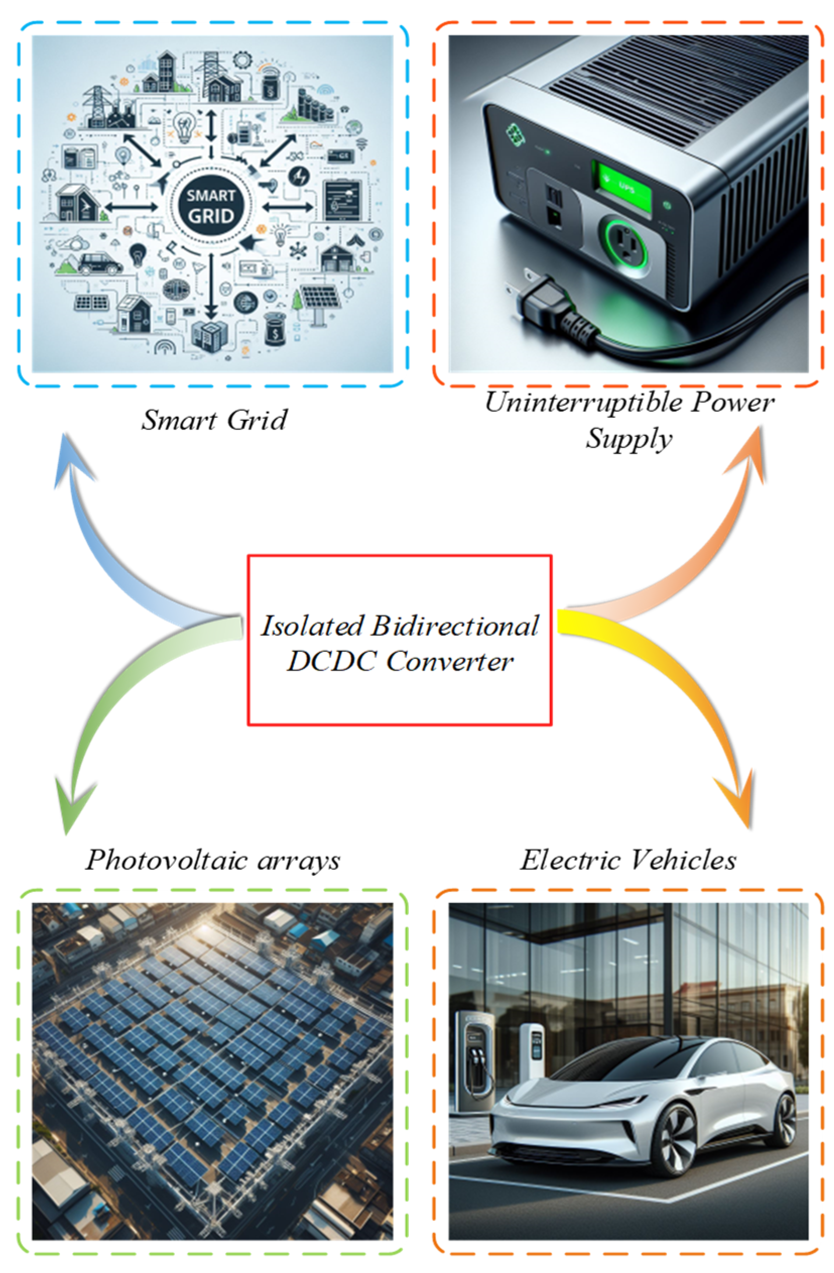
Figure 2.
Principle of operation of IBDC.

Figure 3.
Classification of IBDC.

Figure 4.
Bidirectional forward converter.

Figure 5.
Bidirectional flyback converter.

Figure 6.
Bidirectional push–pull converter.

Figure 7.
Dual active bridge DC–DC converter.

Figure 8.
Principle of operation of bidirectional resonant converter.

Figure 9.
Bidirectional series resonance converter.
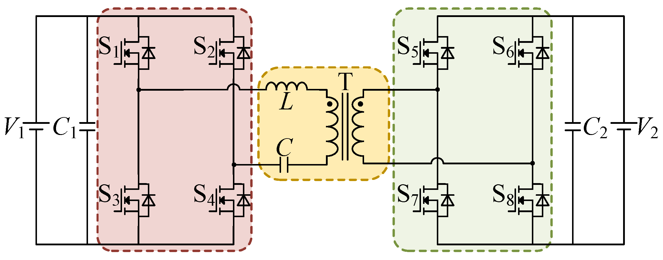
Figure 10.
Bidirectional parallel resonance converter.

Figure 11.
Bidirectional LCC resonance converter.

Figure 12.
Bidirectional LCL resonance converter.

Figure 13.
Bidirectional LLC resonance converter.

Figure 14.
Bidirectional CLLC resonance converter-1.

Figure 15.
Bidirectional CLLC resonance converter-2.

Figure 16.
Bidirectional CLLLC resonance converter.

Figure 17.
PWM switching waveforms. (a) PWM switching waveform of bidirectional forward converter. (b) PWM switching waveform of bidirectional flyback converter. (c) PWM switching waveform of bidirectional push-pull converter.
Figure 17.
PWM switching waveforms. (a) PWM switching waveform of bidirectional forward converter. (b) PWM switching waveform of bidirectional flyback converter. (c) PWM switching waveform of bidirectional push-pull converter.

Figure 18.
DAB converter and bidirectional resonant converter.

Figure 19.
SPS switching waveforms.

Figure 20.
EPS switching waveforms.

Figure 21.
DPS switching waveforms.

Figure 22.
TPS switching waveforms.

Figure 23.
Variable frequency control waveforms.


Table 1.
Comparison of several PWM isolated bidirectional DC–DC converters.
| Converter | Power Control | Advantage | Inferiority | Application Range | Bidirectional Transition Speed |
|---|---|---|---|---|---|
| Bidirectional flyback converter | PWM, phase shifting | Simple structure, low cost, easy drive circuitry | Transformer in unidirectional excitation state, low utilization of transformer | Medium to small power applications | Fast |
| Bidirectional forward converter | PWM, phase-shifting modulation | Simple structure, low production cost, good dynamic response characteristics | Large switch stress when switch is turned off | Low power applications | Fast |
| Bidirectional push–pull converter | PWM, phase-shifting modulation | Simple structure, easy drive circuitry design | Serious biasing issues, high switch stress | Medium to low voltage applications | Fast |
Table 2.
Characteristics of DAB converter.
| Converter | Power Control | Advantage | Inferiority | Soft-Switching Range | Bidirectional Transition Speed |
|---|---|---|---|---|---|
| DAB converter | Phase-shift modulation/Frequency modulation | Simple structure, easy drive circuitry design | Serious biasing issues, high switch stress | Narrow | Fast |
Table 3.
Comparison of several bidirectional resonant converter topologies.
| Converter | Resonant Network Structure | Power Control | Advantage | Inferiority | Soft-Switching Range | Bidirectional Transition Speed |
|---|---|---|---|---|---|---|
| Bidirectional series resonant converter |  | Phase-shift modulation/Frequency modulation | Low current stress, simple control, etc. | No gain adjustment at no load, small soft-switching range. | Narrow | Fast |
| Bidirectional parallel resonant converter |  | Phase-shift modulation/Frequency modulation | Wide voltage gain range, wide soft-switching range for no-load gain adjustment. | High circulating reactive current. | Narrow | Fast |
| Bidirectional LCC resonant converter |  | Phase-shift modulation/Frequency modulation | Wide gain range, good frequency conversion characteristics. | Not suitable for wide output power applications. | Slightly narrow | Fast |
| Bidirectional LCL resonant converter |  | Phase-shift modulation/Frequency modulation | Low reflow power and high efficiency. | Not adapted to wide output power occasions, large size | Slightly narrow | Fast |
| Bidirectional LLC resonant converter |  | Phase-shift modulation/Frequency modulation/Frequency + phase-shift modulation | Wide regulating range, wide soft-switching range, high efficiency, good high-frequency characteristics. | Asymmetric structure with low inverse gain. | Relatively wide | Fast |
| Bidirectional CLLC resonant converter |  or or  | Phase-shift modulation/Frequency modulation/Frequency + phase-shift modulation | LLC structure features in both directions for high efficiency. | Complicated parameter design and large size. | Wide | Slow |
| Bidirectional CLLLC resonant converter |  | Phase-shift modulation/Frequency modulation | Excellent LLC characteristics in both directions, high efficiency, symmetrical structure. | Complicated parameter design and large size. | Wide | Slow |
Table 4.
Converters used in electric vehicle system.
| Specific Applications in Electric Vehicle | The Topology of the Adopted IBDC | The Achieved Results |
|---|---|---|
| EV on-board power supply | Bidirectional CLLLC converter | High voltage gain and high efficiency |
| DAB converter | Wide soft-switching range, low current stress and reactive power loss, compact footprint | |
| Auxiliary power supply for EV | Bidirectional LLC converter | High power density, high efficiency, high system reliability, lightweight |
| Temperature control of electric vehicle batteries | Bidirectional LLC/CLLC converter | High voltage gain, wide soft-switching range, compact footprint, high safety |
| Hybrid power balance | DAB converter and bidirectional series resonance converter | High efficiency, wide soft-switching range, eliminates reactive power loss |
| EV charging | DAB converter | High safety, improved power quality |
| EV drive system | DAB converter | Low cost, high efficiency |
Disclaimer/Publisher’s Note: The statements, opinions and data contained in all publications are solely those of the individual author(s) and contributor(s) and not of MDPI and/or the editor(s). MDPI and/or the editor(s) disclaim responsibility for any injury to people or property resulting from any ideas, methods, instructions or products referred to in the content. |
© 2024 by the authors. Licensee MDPI, Basel, Switzerland. This article is an open access article distributed under the terms and conditions of the Creative Commons Attribution (CC BY) license (https://creativecommons.org/licenses/by/4.0/).
Share and Cite
MDPI and ACS Style
Wang, Z.; Su, X.; Zeng, N.; Jiang, J. Overview of Isolated Bidirectional DC–DC Converter Topology and Switching Strategies for Electric Vehicle Applications. Energies 2024, 17, 2434. https://doi.org/10.3390/en17102434
AMA Style
Wang Z, Su X, Zeng N, Jiang J. Overview of Isolated Bidirectional DC–DC Converter Topology and Switching Strategies for Electric Vehicle Applications. Energies. 2024; 17(10):2434. https://doi.org/10.3390/en17102434
Chicago/Turabian StyleWang, Zhenkun, Xianjin Su, Nianyin Zeng, and Jiahui Jiang. 2024. "Overview of Isolated Bidirectional DC–DC Converter Topology and Switching Strategies for Electric Vehicle Applications" Energies 17, no. 10: 2434. https://doi.org/10.3390/en17102434
Note that from the first issue of 2016, this journal uses article numbers instead of page numbers. See further details here.