
The Influence and Mechanism Analysis of the Longitudinal Magnetic Field on the Microstructure Evolution and Properties of AZ40 Welds


Department of Mechanical Engineering, Taiyuan Institute of Technology, Taiyuan 030008, China
Crystals 2024, 14(5), 449; https://doi.org/10.3390/cryst14050449
Submission received: 12 April 2024
/
Revised: 4 May 2024
/
Accepted: 7 May 2024
/
Published: 8 May 2024
(This article belongs to the Section Crystalline Metals and Alloys)
Abstract
:This paper studied the effect of the longitudinal magnetic field (LMF) on the microstructure evolution and mechanical properties of AZ40 argon tungsten arc welding joints. Magnetic field-assisted argon tungsten arc welding technology was used to achieve butt welding of an AZ40 Mg alloy sheet with a thickness of 1.5 mm. The microstructure of the Mg alloy weld was studied by using metallographic microscopy and scanning electron microscopy. Mechanical performance of the Mg alloy weld was evaluated by using a hardness tester and universal tensile machine. The experimental results revealed that the average crystallite dimension of the weld zone of the Mg alloy joint reached 43 μm without an LMF. By introducing LMF-assisted technology, the weld structure was significantly refined and the average crystallite dimension of the weld seam was reduced by 39.5% to 26 μm with a coil current of 1.2 A. For the joint without magnetic field assistance, the optimum tensile strength of the AZ40 weldment was 225 MPa under a welding current of 80 A, and fracture occurred in the center of joint welding seam. Under an LMF coil current of 1.2 A, the joint strength increased from the initial 225 MPa to 254 MPa, and fracture occurred at the weld edge with obvious plastic fracture characteristics. It can be confirmed that the LMF-assisted welding process effectively improved the microstructure characteristics of the weld seam and strengthened the microhardness and mechanical performance of the AZ40 joint.
1. Introduction
In the face of increasingly serious environmental pollution problems, higher requirements have been put forward for materials used in industrial production in order to reduce pollution and save energy [1,2,3]. Especially for the transportation industry, there is in dire need to develop an efficient connection process that can significantly reduce energy consumption by reducing the weight of institutions. Mg alloy has the characteristic of high specific strength, which can effectively reduce transportation costs [4,5,6]. It has great potential for application in the transportation industry. Different welding techniques such as resistance spot welding, friction stir welding, diffusion welding, laser welding, and argon tungsten arc welding have been developed to weld magnesium and its alloy [7,8,9,10]. Nevertheless, defects such as porosity and grain coarsening are prone to occur in Mg alloy welds, resulting in the comprehensive performance of Mg alloy joints not meeting practical requirements.
For the past few years, LMF auxiliary process has been studied to enhance the welding performance of various alloys [11,12]. The LMF auxiliary welding process was mainly developed according to the principle of the electromagnetic induction (EI) theory. Based on the EI theory, alternating current through the induction coil will lead to alternating the magnetic field, causing an induced current to form in molten bath. Lenz’s law revealed that there was an interaction between the induced current (I) and the alternating magnetic field (B), which ultimately led to the generation of electromagnetic forces. And electromagnetic force drove the molten pool to flow in different directions, ultimately refining the microstructure of the welds by affecting the crystallization process of the molten bath [13,14]. Liu et al. [15] have found that under the influence of LMF, the Lorentz force forced rotational motion to evenly distribute heat on the mother plate and changed the flow trend of liquid metal in the Al alloy melt. It should be noted that compared to welding joints without LMF assistance, joints with LMF assistance had higher mechanical properties. With a coil current of 2.5 A and a magnetic field strength of 17.8 mT, the optimal tensile-shear force of an Al/steel joint reached 2.018 kN, which was 45% higher than that of an Al/steel joint without LMF auxiliary process. Sun et al. [16] investigated the effect of LMF on the cold metal transition welding of Al/Ti alloy. The experimental results indicated that LMF could affect the wettability and flow ability of liquid filler wires. The magnetic field-assisted process reduced the wetting angle of the weld seam and enlarged the welding area, which was beneficial for strengthening the mechanical performance of the welded joint. Under the action of a magnetic field, the maximum tensile-shear force of Al/Ti welded joints was 4.105 kN, which was 93.4% higher than that of traditional arc-welded joints.
This article plans to study the influence of magnetic field assistance on AZ40 Mg alloy arc welding joints through experiments. The welding quality difference between traditional Mg alloy arc welding joints and magnetic field-assisted joints was studied and compared by means of microstructure observation, microhardness testing, tensile strength testing, and fracture characteristics analysis. Finally, the influencing mechanism of the LMF auxiliary welding process was analyzed and discussed.
2. Materials and Methods
The parent metal used in this paper was a 1.5mm thick AZ40 Mg alloy plate, and its chemical composition is listed in Table 1. Pre-welding experiment, the AZ40 plate was processed into a rectangular sample of 60 mm × 60 mm. The oxide skin on the substrate surface was removed with sandpaper and then degreased with acetone. The filling metal was AZ40 wire with a diameter of 1.5 mm, and its chemical composition was the same as that of the Mg alloy base material.
Figure 1 illustrates a sketch diagram of the argon tungsten arc welding of the Mg alloy plate assisted by LMF. In the process of LMF auxiliary welding, a Panasonic YC-400TX pulse machine was applied to carry out the welding of the Mg alloy plate. In Figure 1, the LMF was generated by a coil wound around the iron ring. Due to the application of an LMF to the argon arc, charged particles in the arc moved at a certain angle with the direction of the applied LMF. Eventually, the charged particles cross magnetic field lines, resulting in the formation of Lorentz forces. The charged particles moved circularly around the arc axis, driven by a Lorentz force. Positively charged particles contracted and spiraled around the vertical axis of the arc, while negatively charged particles moved in the opposite direction. In addition, the synchronous movement of the coil and welding gun could effectively reduce magnetic bias blowing. Table 2 shows the main experimental parameters.
Metallographic samples were cut along the direction perpendicular to the weld of the joint, and then grinded, polished and corroded. Finally, the microstructure was observed by using a BETICAL-CR35 optical microscope. A Vickers hardness tester was used to detect the hardness along the vertical and horizontal directions of the weld. The mechanical performance of the AZ40 Mg alloy weldment was tested by utilizing a universal tensile testing machine with a stretching velocity of 1 mm/min. Figure 2 presents a schematic diagram of the stretched sample. In order to reduce the error, six samples were tested for each welding parameter. In addition, the fracture morphologies of the sample were observed and analyzed by using scanning electron microscopy (SEM) equipped with a backscatter electron (BSE) probe.
3. Results and Discussion
3.1. Microscopic Characteristics of Weld
Figure 3 presents the typical morphology of an AZ40 Mg alloy weldment. From Figure 3, it can be observed that both the SEM and BSE images indicate that the Mg alloy joint weld seam was well formed, without welding defects such as holes and cracks. In order to study the effect of an LMF on the microstructure evolution of the weld seam, AZ40 weldments were cut along the direction perpendicular to the length of the weld seam, and the cross section area of the weld seam was polished and corroded to the obtain metallographic structure, as shown in Figure 4. The average grain sizes of the base metal and the weld seam were obtained with the aid of the different magnetic field auxiliary currents, calculated, and listed in Table 3. Figure 4a presents a metallographic diagram of the AZ40 Mg alloy base material. It can be observed that the grains of the base material were small and uniform, with an average grain size of about 14 μm. Figure 4b shows a typical weld metallographic diagram of a Mg alloy joint obtained without the LMF-assisted process. As presented in Figure 4b, the grains in the weld zone become abnormally coarse compared with the Mg alloy parent material, with an average grain size of about 43 μm. According to the Hall Patch formula, the appearance of coarse grains in a weld seam will significantly reduce the mechanical performance of an AZ40 joint. Figure 4c shows the metallographic structure of the weld seam with the assistance of an LMF (coil current of 1.2 A). Obviously, compared with the weld without magnetic field assistance (Figure 4b), the grain morphology of the weld seam was more uniform and the average crystallite dimension was greatly reduced to about 26 μm. The above experimental results indicate that the LMF-assisted welding technology can effectively refine the microstructure of AZ40 welds and enhance welding quality. This was mainly because the electromagnetic force induced by the LMF promoted the rotation of charged particles in the welding arc, and the change in arc shape was conducive to increasing the flow of liquid metal. The high-temperature metal flow continuously scoured the molten pool, making the α-Mg and β-Mg17Al12 eutectic structure in the weld more refined.
3.2. Hardness Analysis
Vickers hardness testing was carried out on the weld zone of the traditional argon arc welding joint and the external magnetic field-assisted joint, respectively, and the results are shown in Figure 5. For the horizontal direction of the weld seam, Figure 5a indicates that the hardness value of the weld seam area was significantly lower than that of the parent Mg alloy material. As mentioned in the above section, the decrease in the hardness value of the weld zone is mainly attributed to the grain coarsening. It is well known that micro hardness results can reflect the microstructure variation in materials. Tabor’s empirical formula indicates that the smaller the average crystallite dimension, the higher the micro hardness [4]. As the magnetic field-assisted process was applied during the arc welding process of the AZ40 Mg alloy, the crystallite dimension of the weld seam was refined and the microhardness value was also increased, as shown in Figure 5b. Compared with Figure 5a, it is worth noting that the magnetic field-assisted process not only improved the Vickers hardness value of the weld zone but also reduced the fluctuation in the hardness value of the weld seam. Figure 5c,d shows the hardness test results in the vertical direction of the weld seam of the Mg alloy weldment. Similar to the distribution pattern of the hardness in the horizontal direction, the magnetic field-assisted process also increased the hardness value of the weld in the vertical direction and stabilized the hardness value. Similar experimental results were reported by Li et al. [12].
3.3. Tensile Strength and Fracture Features
Figure 6 reveals the effect of an LMF on the strength of Mg alloy joints. Figure 6 indicates that the influence of magnetic field assistance on the strength of the AZ40 weldment was mainly manifested as follows: as the magnetic field current increased, the strength of the AZ40 joint first increased and then decreased. For traditional Mg alloy argon arc welding joints (coil current of 0 A), the tensile strength of AZ40 weldment is only 225 MPa, owing to the abnormally large grain size in the weld seam during the solidification process of the molten pool. With a coil current of 0.3–1.2 A, the tensile strength of the AZ40 weldment continued to increase. When the magnetic field current was 1.2 A, the optimal tensile strength of the AZ40 joint reached 254 MPa, which was 12.9% higher than the joint without LMF assistance. At this point, the weld strength was slightly lower than the strength of the AZ40 Mg alloy base material (262 MPa). The LMF significantly enhanced the strength of the Mg alloy joints, mainly because the magnetic field auxiliary process improved the microstructure of AZ40 weldment, as presented in Figure 4. According to the Hall Patch formula, the finer the grain size in the weld seam, the higher the joint strength. As the magnetic field current continued to increase, the tensile strength of the AZ40 weldment decreased slightly. This is because with the increase in induced current, there is an increased thermal effect in the melt pool, which reduces the degree of supercooling and the nucleation rate, ultimately affecting the mechanical performance of the weldment. In terms of the typical stress–strain curve of AZ40 joints (Figure 7), it can be found that the LMF auxiliary welding process not only greatly improves the tensile strength of the AZ40 weldment but also effectively improved the elongation of the joints.
Figure 8 and Figure 9 present the typical fracture characteristics of Mg alloy joints. Figure 8 and Figure 9 indicate that the external magnetic field-assisted welding technique had a significant impact on the fracture characteristics of the AZ40 weldment. For traditional arc welding joints, the coarse crystallite dimension in the weld zone led to a deterioration in the mechanical properties. In this case, fracture occurred in the weak weld zone under the action of the electronic tension machine (Figure 8a) and there was a large platform on the fracture surface (Figure 9a). As indicated earlier, the external magnetic field-assisted technology effectively improved the microstructure of weld seam, resulting in a significant reduction in grain size. At this point, the mechanical performance of the weld zone was strengthened, and fracture occurred near the base metal (Figure 8b). The fracture surface exhibited obvious plastic fracture features (Figure 9b).
3.4. Mechanism of LMF-Assisted Welding
The above experimental results verify that the LMF auxiliary welding process can refine the microstructure of weld seams and enhance the mechanical performance of AZ40 weldments. According to the principle of electromagnetic induction, as a coil passed through alternating current an alternating magnetic field B was generated, which in turn generated an induced current I in the molten bath. The interaction between the induced current (I) and the alternating magnetic field (B) ultimately produced a Lorentz force, F, as shown in Figure 10. The influence mechanism of Lorentz forces on joints mainly include the following two aspects. On the one hand, there is the electromagnetic stirring effect. With the external magnetic field applied in the argon arc welding of the AZ40 Mg alloy, the magnetic field produced an electromagnetic stirring effect on the molten bath and drove the liquid metal flow in the molten bath. In addition, during the initial crystallization process, the dendrites grown in the melt pool broke into fragments. Apparently, these dendritic fragments served as new nucleation points, which were beneficial for improving the nucleation rate of the weld and ultimately refining the weld microstructure. Simultaneously, the semi-melted structures at the edge of the molten bath were stripped into the molten bath and became new nucleating particles to further refine the grain. On the other hand, in the argon arc welding process of the Mg alloy, a large temperature gradient was formed in the molten bath, which promoted the formation of coarse structure. However, the application of the LMF auxiliary process promotes the flow of the molten bath and reduces the temperature gradient, thereby effectively refining the microstructure of AZ40 welds.
In addition to electromagnetic stirring, the magnetic field also has an electromagnetic damping effect on the molten bath. According to the theory of electromagnetics, when a current with a current density of I passes through a metal with a resistance of R and a specific heat capacity of c, the following thermal effect Q is generated:
As the mass of the molten pool was m, the thermal effect caused the temperature of the molten bath to increase by :
If , the temperature change caused by induced current can be simplified as follows:
For a certain welding pool, the decrease in temperature is directly proportional to the square of the induced current. The constant D reflects the sensitivity of undercooling to the Joule heating effect, which is therefore referred to as the undercooling sensitivity coefficient.
According to Equation (3), the induced current generated by the LMF has a dual function. On the one hand, it strengthened the flow of the molten bath and promoted grain refinement, which increased the tensile strength and hardness of the Mg alloy welded joints. On the other hand, the reduced undercooling led to a coarsening of the microstructure of the AZ40 Mg alloy weldment and a decrease in the mechanical properties. Under the combined effect of the two aspects, it can be determined from the above experimental results that when the magnetic field current was set to 1.2 A, the Mg alloy welded joint had excellent welding quality.
4. Conclusions
This paper studied the influence and mechanism analysis of an LMF on the microstructure and properties of AZ40 welds, and the conclusions are summarized as follows:
- With a magnetic field current of 1.2 A, the average crystallite dimension of the weld seam of the joint decreased from an initial state of 43 μm to 26 μm, indicating that the LMF auxiliary welding process had an obvious grain refinement effect.
- The magnetic field-assisted process not only enhanced the microhardness of the weld seam but also reduced the fluctuation in the hardness value of the weld seam.
- With a magnetic field current of 1.2 A, the joint strength reached 254 MPa, which was 12.9% higher than that of the AZ40 joint without LMF assistance.
Funding
This research received no external funding.
Data Availability Statement
The original contributions presented in the study are included in the article, further inquiries can be directed to the corresponding author.
Conflicts of Interest
The author declares no conflicts of interest.
References
- Yang, J.; Su, J.H.; Yu, Z.S.; Zhang, G.Z.; Lin, S.B.; Li, Y.L.; Zhou, N.Y. Influence of Ni interlayer width on interfacial re-actions and mechanical properties in laser welding/brazing of Al/Mg lap joint. Sci. Technol. Weld. Join. 2020, 25, 37–44. [Google Scholar] [CrossRef]
- Xu, C.; Yuan, X.J. Effect of ultrasonic field parameters on interfacial characteristics and mechanical properties of Mg alloy welding joint. Mater. Lett. 2022, 306, 130962. [Google Scholar] [CrossRef]
- Xiong, Y.; Jiang, Y. Compressive deformation of rolled AZ80 magnesium alloy along different material orientations. J. Mater. Sci. 2020, 55, 4043–4053. [Google Scholar] [CrossRef]
- Xu, C.; Yuan, X.J. The study of microstructure, corrosion resistance and mechanical properties of ultrasonic assisted welding-brazing of Ti-Mg. J. Mater. Res. Technol. 2022, 17, 467–477. [Google Scholar] [CrossRef]
- Feng, M.N.; Luo, Z. Interface morphology and microstructure of high-power ultrasonic spot welded Mg/Al dissimilar joint. Sci. Technol. Weld. Join. 2019, 24, 63–78. [Google Scholar] [CrossRef]
- Lei, Z.; Bi, J.; Li, P.; Li, Q.; Chen, Y.B.; Zhang, D.M. Melt flow and grain refining in ultrasonic vibration assisted laser welding process of AZ31B magnesium alloy. Opt. Laser Technol. 2018, 108, 409–417. [Google Scholar] [CrossRef]
- Li, G.; Zhou, L.; Luo, S.; Dong, F.; Guo, N. Quality improvement of bobbin tool friction stir welds in Mg-Zn-Zr alloy by adjusting tool geometry. J. Mater. Process. Technol. 2020, 282, 116685. [Google Scholar] [CrossRef]
- Xu, C.; Sheng, G.M.; Wang, H.D.; Jiao, Y.J.; Yuan, X.J. Effect of high energy shot peening on the microstructure and me-chanical properties of Mg/Ti joints. J. Alloys Compd. 2017, 695, 1383–1391. [Google Scholar] [CrossRef]
- Zhang, G.Q.; Tong, X.; Wu, G.H.; Zhang, L.; Sui, H.; Zhang, X. Research on the post-weld heat treatment of TIG repair welded joint of sand-cast Mg-Y-RE-Zr alloy. Mater. Sci. Eng. A 2021, 821, 141577. [Google Scholar] [CrossRef]
- Tang, J.W.; Chen, L.; Zhao, G.Q.; Zhang, C.; Chu, X. Formation mechanism of abnormal coarse grains on weld seam of extruded ZK60 alloy and the effects on mechanical properties. Mater. Sci. Eng. A 2020, 773, 138718. [Google Scholar] [CrossRef]
- Wang, J.F.; Sun, Q.; Zhang, T.; Zhang, S.; Liu, Y.; Feng, J. Arc characteristics in alternating magnetic field assisted narrow gap pulsed GTAW. J. Mater. Process. Technol. 2018, 254, 254–264. [Google Scholar] [CrossRef]
- Li, Y.; Luo, Z.; Yan, F.Y.; Duan, R.; Yao, Q. Effect of external magnetic field on resistance spot welds of aluminum alloy. Mater. Des. 2014, 56, 1025–1033. [Google Scholar] [CrossRef]
- Li, Y.B.; Zhang, Q.X.; Qi, L.; David, S.A. Improving austenitic stainless steel resistance spot weld quality using external magnetic field. Sci. Technol. Weld. Join. 2018, 23, 619–627. [Google Scholar] [CrossRef]
- Pereira, D.; Oliveira, J.P.; Pardal, T.; Miranda, R.M.; Santos, T.G. Magnetic pulse welding: Machine optimisation for aluminium tubular joints production. Sci. Technol. Weld. Join. 2017, 23, 172–179. [Google Scholar] [CrossRef]
- Liu, Y.B.; Sun, Q.J.; Liu, J.P.; Wang, S.; Feng, J. Effect of axial external magnetic field on cold metal transfer welds of aluminum alloy and stainless steel. Mater. Lett. 2015, 152, 29–31. [Google Scholar] [CrossRef]
- Sun, Q.; Li, J.; Liu, Y.; Li, B.; Xu, P.; Feng, J. Microstructural characterization and mechanical properties of Al/Ti joint welded by CMT method—Assisted hybrid magnetic field. Mater. Des. 2017, 116, 316–324. [Google Scholar] [CrossRef]
Figure 1.
Schematic illustration of LMF auxiliary welding of AZ40 Mg alloy plate.

Figure 2.
Schematic drawing sample of Mg alloy joint.

Figure 3.
Typical morphology of an AZ40 weldment with the longitudinal magnetic field (LMF) auxiliary process (coil current of 1.2 A): (a) scanning electron microscopy (SEM) image of AZ40 weldment, (b) backscatter electron (BSE) image of AZ40 weldment.
Figure 3.
Typical morphology of an AZ40 weldment with the longitudinal magnetic field (LMF) auxiliary process (coil current of 1.2 A): (a) scanning electron microscopy (SEM) image of AZ40 weldment, (b) backscatter electron (BSE) image of AZ40 weldment.

Figure 4.
Metallographic structure diagram of AZ40 weldment: (a) base material, (b) weld area of argon arc welding joint, (c) weld area of magnetic field-assisted argon arc welding joint.
Figure 4.
Metallographic structure diagram of AZ40 weldment: (a) base material, (b) weld area of argon arc welding joint, (c) weld area of magnetic field-assisted argon arc welding joint.

Figure 5.
Weld hardness testing results: (a) horizontal direction without LMF, (b) horizontal direction with coil current of 1.2 A, (c) vertical direction without LMF, (d) vertical direction with coil current of 1.2 A.
Figure 5.
Weld hardness testing results: (a) horizontal direction without LMF, (b) horizontal direction with coil current of 1.2 A, (c) vertical direction without LMF, (d) vertical direction with coil current of 1.2 A.

Figure 6.
The influence of LFM current on the strength of AZ40 weldment.
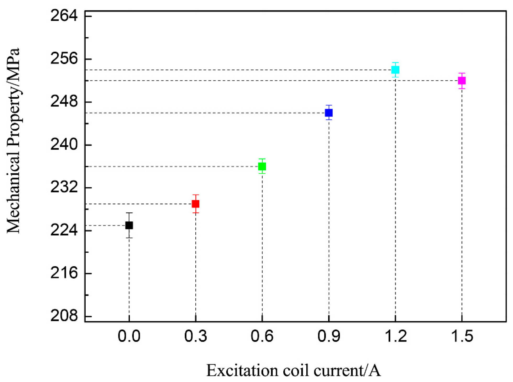
Figure 7.
Typical stress–strain curves of AZ40 Mg alloy joints: (a) without magnetic field, (b) with coil current of 1.2 A.
Figure 7.
Typical stress–strain curves of AZ40 Mg alloy joints: (a) without magnetic field, (b) with coil current of 1.2 A.
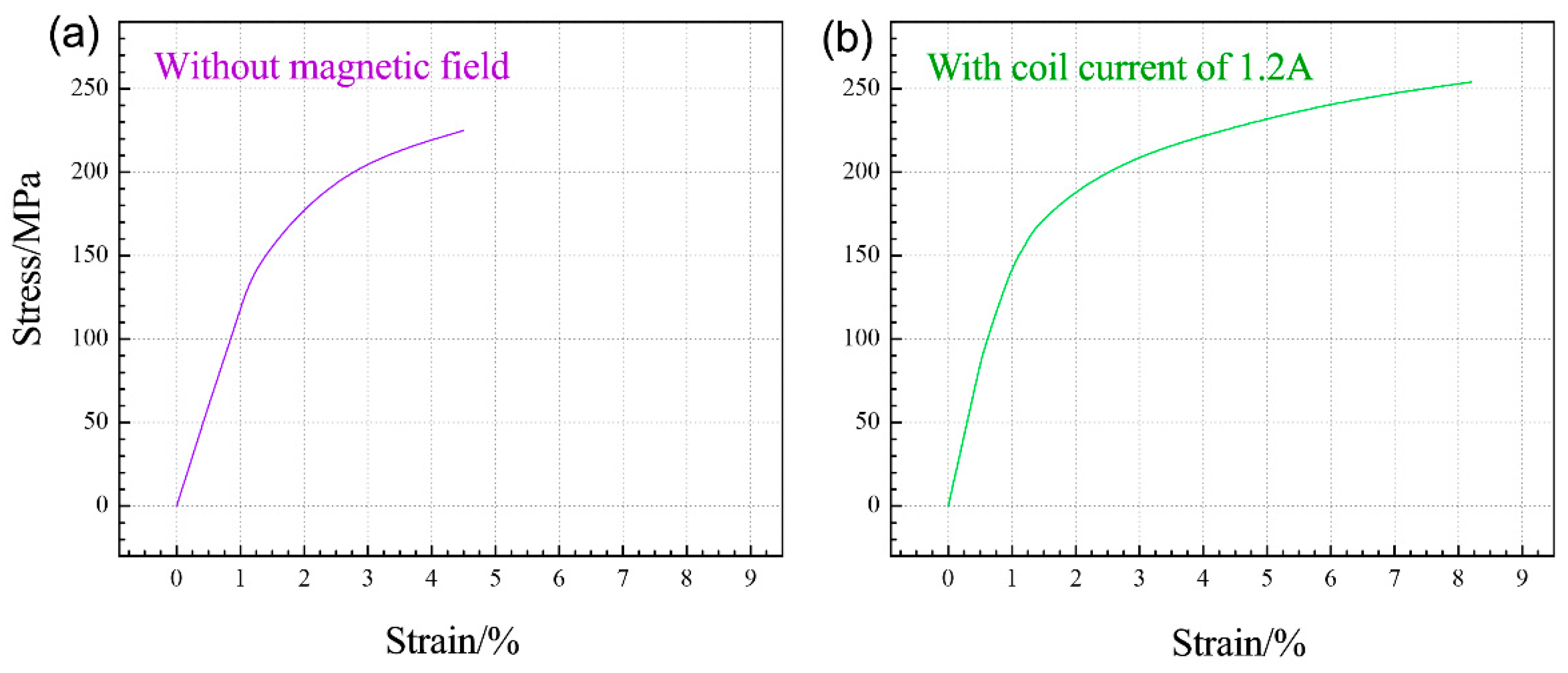
Figure 8.
Fracture location of AZ40 weldment: (a) without magnetic field, (b) with coil current of 1.2 A.
Figure 8.
Fracture location of AZ40 weldment: (a) without magnetic field, (b) with coil current of 1.2 A.

Figure 9.
Fracture characteristics of AZ40 weldment: (a) without magnetic field, (b) with coil current of 1.2 A.
Figure 9.
Fracture characteristics of AZ40 weldment: (a) without magnetic field, (b) with coil current of 1.2 A.

Figure 10.
LMF auxiliary welding mechanism illustration of AZ40 Mg alloy.


Table 1.
The main chemical composition of parent material (wt.%).
| Element | Zn | Mn | Fe | Al | Mg |
|---|---|---|---|---|---|
| AZ40 | 0.8 | 0.3 | 0.02 | 4.2 | Bal. |
Table 2.
The main experimental parameters applied in LMF welding of AZ40 plate.
| Parameter | Value |
|---|---|
| Welding current/A | 80 |
| Welding voltage/V | 12 |
| Arc length/mm | 2 |
| Argon flow rate/(L·min−1) | 10 |
| Coil current/A | 0.3–1.5 |
Table 3.
The average grain size of the base metal and the weld seam obtained with various magnetic field auxiliary currents.
Table 3.
The average grain size of the base metal and the weld seam obtained with various magnetic field auxiliary currents.
| Sample | Base Metal | AZ40 Joint (0A) | AZ40 Joint (0.3A) | AZ40 Joint (0.6A) | AZ40 Joint (0.9A) | AZ40 Joint (1.2 A) | AZ40 Joint (1.5A) |
|---|---|---|---|---|---|---|---|
| Average grain size (μm) | 14 | 43 | 41 | 37 | 32 | 26 | 30 |
Disclaimer/Publisher’s Note: The statements, opinions and data contained in all publications are solely those of the individual author(s) and contributor(s) and not of MDPI and/or the editor(s). MDPI and/or the editor(s) disclaim responsibility for any injury to people or property resulting from any ideas, methods, instructions or products referred to in the content. |
© 2024 by the author. Licensee MDPI, Basel, Switzerland. This article is an open access article distributed under the terms and conditions of the Creative Commons Attribution (CC BY) license (https://creativecommons.org/licenses/by/4.0/).
Share and Cite
MDPI and ACS Style
Wang, J. The Influence and Mechanism Analysis of the Longitudinal Magnetic Field on the Microstructure Evolution and Properties of AZ40 Welds. Crystals 2024, 14, 449. https://doi.org/10.3390/cryst14050449
AMA Style
Wang J. The Influence and Mechanism Analysis of the Longitudinal Magnetic Field on the Microstructure Evolution and Properties of AZ40 Welds. Crystals. 2024; 14(5):449. https://doi.org/10.3390/cryst14050449
Chicago/Turabian StyleWang, Jianghui. 2024. "The Influence and Mechanism Analysis of the Longitudinal Magnetic Field on the Microstructure Evolution and Properties of AZ40 Welds" Crystals 14, no. 5: 449. https://doi.org/10.3390/cryst14050449
Note that from the first issue of 2016, this journal uses article numbers instead of page numbers. See further details here.