
Analysis of Microwave-Induced Damage in Granite Aggregates Influenced by Mineral Texture
1
School of Science, Xi’an University of Architecture and Technology, Xi’an 710055, China
2
Postdoctoral Station of Architecture, Xi’an University of Architecture and Technology, Xi’an 710055, China
3
Shaanxi Key Laboratory of Geotechnical and Underground Space Engineering, Xi’an University of Architecture and Technology, Xi’an 710055, China
4
School of Civil Engineering, Xi’an University of Architecture and Technology, Xi’an 710055, China
*
Author to whom correspondence should be addressed.
Buildings 2024, 14(5), 1348; https://doi.org/10.3390/buildings14051348
Submission received: 15 April 2024
/
Revised: 3 May 2024
/
Accepted: 6 May 2024
/
Published: 9 May 2024
(This article belongs to the Section Construction Management, and Computers & Digitization)
Abstract
:The use of microwave energy to recycle high-quality coarse aggregates from waste concrete or assist hard rock breakage in underground building engineering is promising. Controlling or promoting the damage of coarse aggregates, i.e., hard rocks, under microwave irradiation is a crucial issue faced by these techniques. Understanding the damage mechanisms of hard rocks exposed to microwaves is thus urgent. Fracture toughness is a significant mechanical parameter of rocks that reflects their ability to resist crack propagation and damage evolution. In this study, the fracture toughness degradation of microwave-heated granite was investigated by combining experimental investigations and numerical simulations. A three-point-bending (TPB) experiment was conducted on granite specimens after microwave irradiation. A coupled electromagnetic–thermal–mechanical model considering the actual mineral texture of the granite specimen was established. The evolution of the temperature gradient and stress field near the initial notch tip were investigated. The results suggest that the microwave-induced maximum temperature gradient and stress in granite are at the plagioclase–quartz (Pl–Qtz) interfaces or inside the Pl near the boundary. The region of cracking initiation was defined as the damage zone, which could be obtained by comparing the microwave-induced thermal stress with the critical value. The fracture toughness degradation, which corresponds to the evolution of the damage zones, can be divided into two stages. A relatively rapid decrease in fracture toughness in the first stage is primarily caused by the spread of the scattered damage zones along the Pl–Qtz interfaces; subsequently, a gentler fracture toughness degradation results mainly from the extension of the previous damage zones.
1. Introduction
Microwave energy, in the form of electromagnetic waves, can be absorbed by dielectric media and converted to effective heat. The heating process is selective, volumetric, and instantaneous. Therefore, microwave-heating technology has been widely used in the drying, organic synthesis, and pyrolysis of biomass or waste [1]. The dielectric properties of the constituents of concrete and hard rocks are quite distinct. Microwave irradiation technology has also been introduced in civil engineering for the selective heating of constituents. Microwave removal has been proven effective in minimizing or even completely removing adhering mortar from recycled coarse aggregates (RCAs) [2,3,4]. Although the microstructure of RCAs can be significantly improved, using microwaves to control the energy input and avoid overheating damage to aggregates remains a challenge. On the other hand, tunnel boring machines are widely employed for rock excavation in underground building engineering owing to advantages such as continuous operation, personnel safety, and low excavation disturbance [5]. However, the mechanical breakage is hindered by the high noise and wear rate of the hobs. Thus, there is an urgent need for a more sustainable method for breaking hard rocks more efficiently. Microwave-assisted mechanical rock breakage is one of the most promising rock-breaking technologies [6,7,8]. The knowledge gap between the minimum microwave energy consumption and the maximum rock damage is a major obstacle to the successful application of microwave-assisted rock breakage technology.
The mechanism of rock damage evolution under microwave irradiation is the basis for controlling the damage of coarse aggregates in concrete recycling and for promoting rock damage in rock-breaking engineering. Rock consists of different minerals; each mineral component is heated directly and variously depends on the dielectric properties when subjected to microwaves, whereas it is heated by thermal conduction using the conventional method. The thermal effects on rock properties induced by microwaves differ from those caused by conventional heating methods [9,10]. Kahraman et al. [11] investigated the influence of microwave treatment on the strengths of nine different igneous rocks and found that the compressive and tensile strengths of granite decreased with increasing temperature after 200 °C and 100 °C, respectively. However, continuous losses in the compressive and tensile strengths of syenite and gabbro were observed during heating. A decrease in the strength of rocks is influenced by the mineral content, especially in highly microwave-absorbing minerals. Rocks that demonstrate the greatest reduction in strength typically contain approximately 2–20 wt% of highly microwave-absorbing minerals [12]. Yao et al. [13] and Yin et al. [14] found that the rock specimens treated with the same microwave energy, high power, and low exposure time could sustain more damage than those treated with low power and long irradiation times.
Extensive experimental studies have shown that microwave heating can significantly degrade rock strength. However, it is difficult to obtain the interior electromagnetic, thermal, and mechanical variations in rocks based solely on experimental studies. Numerical simulation provides another efficient method for assessing the damage and fracturing of hard rocks subjected to microwave irradiation. An electromagnetic–thermal–mechanical coupled model of cylindrical basalt samples was established by Xu et al. [15]. The mechanical property parameters of the rock at the mesoscale were assumed to follow a statistical distribution to reflect the material heterogeneity in the numerical model. The damage behavior induced by high thermal gradients was described by a constitutive law, which is for isotropic and elastic materials. The coupled electromagnetic–heating–stress–damage process of shale irradiated by microwaves was investigated by Cui et al. [16]. Microwave heating was simulated for a cylindrical sample, and the resulting stress–damage response was examined for two minerals that were stacked as lamellae. The effect of realistic microstructure on the microwave-induced strength degradation in rocks was not considered.
The temperature gradients are induced in rocks due to the selective heating of minerals and thermal conduction under microwave irradiation. Thermal stress is generated because of thermal expansion mismatches between adjacent minerals. Once the thermal stress reaches the criteria, propagation of initial cracks and generation of new cracks occur to reduce the mechanical properties of rocks [17,18,19,20]. Thermal stress is generated in microwave-heated rocks, which are strongly influenced by theirmineral texture. The stress distribution of models consisted of a single ‘circular’ particle of pyrite within a ‘square’ sample of calcite, as studied by Jones et al. [21]. The stress regime inside a heated mineral particle, i.e., pyrite, was compressive, while outside the boundary, shear and tensile stresses were predominant. As the size of the heated particle decreased, a decrease in the shear stress, which could damage the rock, was shown. For the model of a single disc-shaped grain of pyrite surrounded by a larger disc of calcite, the tensile stress occurred in the calcite matrix, and the maximum value was beyond the interface of the two minerals under microwave irradiation [22]. A microwave-induced stress field in granite solved by an uncoupled method was presented by Toifl et al. [23]. A three-component artificial microstructure of the granite was constructed in the research. The largest stresses were observed at the boundaries of the Pl grains. The stress field influenced by the distribution of Qtz and muscovite is not mentioned in the study. It is essential to investigate the stress field evolution under coupled electromagnetic–thermal–mechanical multiphysics with a realistic microstructure of rocks for analyzing the damage mechanism.
Fracture toughness is a crucial mechanical parameter of rocks that reflects their ability to resist crack propagation and damage evolution. Crack propagation tends to be induced primarily by tensile stress. Mode I fracture toughness, i.e., the critical stress intensity factor under a pure tension load, plays a vital role in studying the mechanism of rock damage [24,25]. Dynamic fracture tests of microwave-heated granite were conducted by Li et al. [26], and the results showed that both the propagation fracture toughness and fracture energy were sensitive to the irradiation duration and decreased with increasing irradiation duration. The results of static fracture tests also showed a significant decrease in fracture toughness with the input of microwave energy [27,28]. The effects of microwave irradiation on the fracture toughness of hard rocks were investigated experimentally in the aforementioned studies. Because the fracture toughness reduction of hard rocks subjected to microwaves is susceptible to mineralogy texture and microwave energy parameters, it is difficult and costly to investigate the effects of microwave irradiation on the fracture toughness of rock comprehensively through laboratory experiments alone. Recent advancements in numerical methods may lead to significant improvements in addressing this issue. A finite-element-based numerical model was employed by Deyab et al. [29] to maximize the microwave energy absorption of the sample, and the minimum required diameter of the basalt rock specimen for fracture toughness experiments after microwave treatment was determined. Further investigation of the mechanism of fracture toughness degradation in hard rocks subjected to microwave energy is urgently required.
This study aims to quantitatively assess the relationship between microwave-induced physical fields and the fracture toughness degradation of hard rocks. Granite is a common hard rock that is widely used for concrete coarse aggregates; thus, it was selected for this research. A TPB experiment was conducted on microwave-heated granite specimens to study the reduction in fracture toughness, and the corresponding heating response of granite under microwave irradiation was simulated numerically. Furthermore, a coupled electromagnetic–thermal–mechanical model considering the realistic mineral texture was developed, and the evolutions of temperature fields and synergistic stress fields around the notch tip were investigated. Consequently, the mechanism of fracture toughness degradation in hard rocks caused by stress-induced crack propagation was elucidated.
2. Specimens and Experimental Methods
2.1. Specimen Preparation
Granite sourced from Yueyang in Hubei Province, China, was used in this research. Three-point bending notched (TPBN) granite beams, obtained from the same intact rock, were prepared according to the American Society for Testing and Materials (ASTM) standards [30] to investigate the degradation of fracture toughness in rock under microwave irradiation, as shown in Figure 1. The initial notch was machined using a rotary diamond-impregnated saw (width of 0.5 mm), and the length of the notch was mm.
The results of standard petrographic tests showed that granite with a medium-grained texture primarily consisted of 62% Pl, 30% Qtz, 5% biotite (Bt), and other minor minerals. The grain sizes of Pl and Qtz were in the ranges of 0.40 mm × 0.80 mm to 0.80 mm × 2.50 mm and 0.40 mm × 0.80 mm to 0.80 mm × 1.50 mm, respectively. Relatively fine Bt particles (<0.5 mm) were observed in the granite specimens.
2.2. Testing Procedure
A multimode industrial microwave-heating system (CY-MU1000CL, as demonstrated in the research [31]) with a frequency of 2.45 GHz and a maximum power of 6 kW was employed for the microwave-heating tests (Figure 2). Granite specimens were irradiated at 5 kW for various exposure times. Preliminary tests revealed that the local fracture or melting of the TPBN specimens occurred when the irradiation time exceeded 1800 s. The TPBN granite specimens were irradiated for 360, 720, 1080, 1440, and 1800 s in this research. Three parallel specimens were included for each group of microwave irradiation parameters, and the number of specimens was 18, including three untreated specimens. The specimen surface temperature was measured during heating using a thermocouple installed in the heating cavity.
In accordance with the ASTM recommendations [32], the TPBN specimen (shown in Figure 1), which contains a straight, sharp crack of length was subjected to three-point bending; its loading configuration is shown in Figure 2. The geometry of the specimen was first proposed by the ASTM standard for determining the fracture toughness of metallic material. Subsequently, the specimen was used to perform a Mode I fracture toughness test on limestone [33]. The relationship between the span and the height of the specimen should be . TPB experiments were conducted using an electronic universal testing machine (CSS-88100, SINOMACH, Beijing, China), which is shown in Figure 2, with a maximum load of 300 kN, and the displacement rate of the loading process was 0.01 mm/min. The load–displacement relationship of the granite specimens was obtained and used to calculate their fracture toughness.
3. Mathematical Modeling of Microwave Heating of Granite
3.1. Model Assumptions
To clarify the distributions of electric and temperature fields within granite during microwave heating, numerical simulations were performed using COMSOL Multiphysics to address the electromagnetic–thermal interactions and heat transfer in the rock. The following assumptions were made in this study [34].
- (1)
- The metallic microwave-heating cavity was made of copper and full of air.
- (2)
- The initial temperature of the rock sample was considered to be homogeneous and isotropic.
- (3)
- Phase change, mass transfer, and chemical reactions were assumed to be absent in the microwave-heated rock.
3.2. Geometry and Meshing
A microwave-heated granite model was established based on the structural size of the experimental microwave oven and the TPBN rock specimens. As shown in Figure 3, the model was composed of four rectangular waveguides (100.00 mm × 86.36 mm × 43.18 mm), a cubic cavity (420 mm × 420 mm × 320 mm), and a TPBN granite specimen. The microwave power transmitted by each waveguide was kW at a frequency of 2.45 GHz, and the input of the total power was 5 kW. The thermal and electric properties of the materials (granite specimen, copper, and air) reported in the literature [34,35] are shown in Table 1 and Table 2 and Figure 4.
To determine the optimal mesh size for the established model, nine meshing schemes of the physics-controlled mesh type with different element sizes provided in COMSOL Multiphysics were inspected. The surface temperature at the center of the granite specimen (0, 0, 20) was irradiated at 5 kW for 1080 s with each meshing scheme simulated. A mesh-independent solution can be obtained by comparing the results obtained using an extremely coarse mesh, followed by other mesh adaptations until the error or difference in the computed temperature is less than 1% [36]. Therefore, two meshing schemes, i.e., finer and extra-fine, can be adopted, as shown in Figure 5, and the extra-fine meshing type was selected in this study.
3.3. Governing Equations and Boundary Conditions of Multiphysics
Electromagnetic and thermal physics were employed to study the microwave-induced temperature evolution in granite. The electromagnetic physics solution is based on Maxwell’s theory, and the corresponding governing equation for this part of the model is given as follows [37]:
where (N/A2) is the relative permeability; (F/m) is the permittivity of free space and F/m; (F/m) is the relative permittivity; (rad/s) is the angular frequency; (S/m) is the electrical conductivity; (rad/m) is the wave number of free space; and (V/m) is the electric field intensity.
The thermal physics-governing equations are expressed as follows [38]:
where is heat flux term due to thermal conduction; (W/(m·K)) and (kg/m3) are thermal conductivity and density of the rock, respectively; (J/(kg·K)) is the specific heat capacity at constant pressure; (m/s) is the velocity vector of translational motion; and (W/m3) denotes the electromagnetic heat source.
Electromagnetic loss is considered a heat source in thermal physics. Electromagnetic and thermal multiphysics are coupled. The following initial conditions were applied to the model: Both the initial air and the surface temperature of the granite specimens were set at approximately room temperature, i.e., °C.
The boundary conditions for the different multiphysics of the model are as follows: In electromagnetic physics, to ensure that electromagnetic waves remain inside the heating cavity, the metallic walls of the heating cavity and waveguides are assigned impedance boundary conditions. The impedance boundary condition is expressed as follows:
where (H/m) is the permeability of free space and H/m; (V/m) is the source electric field; and (A/m) is the magnetic field intensity. Thus, the electromagnetic fields can be solved in the frequency domain. The port type of the waveguide is set as rectangular, and the port is excited using a transverse electric TE10 mode.
A fully insulated boundary condition was assumed for the thermal physics because the granite was heated in a heat-insulating layer [39]. The heat-insulating layer is transparent to microwaves and has no impact on the dielectric loss in the specimen. The insulated boundary condition applied to the outer surface of granite is expressed as follows:
where is the normal vector toward the exterior boundary.
4. Results
4.1. Microwave-Heating Response in Granite
The temperature rise at the center of the top surface of the specimen was measured, as shown in Figure 6. The microwave-heating process was divided into five stages (S1, S2, …, S5) according to the average heating rate. The average heating rate at S1 with an exposure time of 0–100 s was 1.5 °C/s, and an approximately linear increase in temperature occurred at this stage. The heating rate decreased to 0.46 °C/s at S2 with an exposure time of 100–300 s. The average heating rates at S3 (300–600 s), S4 (600–1200 s), and S5 (1200–1800 s) were 0.24, 0.12, and 0.04 °C/s, respectively. This indicates a significant downward trend in the heating rate with exposure time. This is because of the interactions between the temperature and thermal properties of the rock, as shown in Figure 4.
The distribution of the electric field norm in microwave heating cavities and granite is shown in Figure 7. It can be seen that the electric field in the microwave heating cavity was influenced by the granite specimen. The variations in the dielectric properties of granite in the temperature range were not distinct, and the electric field norm in the rock remained nearly unchanged with the increasing exposure time under a constant level of microwave power. The minimum and maximum values of the electric field in granite were 3.56 × 10³ and 4.43 × 10⁴ V/m that were induced at the points (−5.00, 25.27, 1.24) and (9.44, 0.25, 8.00), respectively.
The temperature fields of granite specimens irradiated for 100, 300, 600, 1200, and 1800 s were analyzed, as shown in Figure 8. The analysis revealed that the difference between the maximum and minimum values of the temperature field increased with exposure time. A strongly heated area was observed at each exposure time point. The range of the strongly heated area increased with irradiation time at 0–600 s but showed a downward trend at 600–1800 s. This is because of the interactions between the temperature rise and the thermal properties of the rock. Moreover, the numerical results of the temperature increase were consistent with the experimental results; thus, the reliability of the numerical simulation results was validated.
To study the mechanism of fracture toughness degradation in the subsequent section, the temperature fields around the initial notch were investigated further. The temperature evolutions adjacent to the top of the initial notch along the x- and y-directions irradiated for 360, 720, 1080, 1440, and 1800 s are shown in Figure 9. A mildly fluctuating temperature along the x-direction was shown for each exposure time interval, and the minimum temperature occurred at mm. The average temperatures from to mm were 295 °C (t = 360 s), 383 °C (t = 720 s), 429 °C (t = 1080 s), 452 °C (t = 1440 s), and 471 °C (t = 1800 s). The temperature decreased monotonically around the notch along the y-direction. The average temperatures from to mm were 293 °C (t = 360 s), 377 °C (t = 720 s), 426 °C (t = 1080 s), 449 °C (t = 1440 s), and 468 °C (t = 1800 s). The average temperatures along the x-direction were slightly higher than those along the y-direction for the same range.
4.2. Load–Displacement Relationship of Microwave-Heated Granite
The failure process of the microwave-heated granite in the TPB tests was captured through the load–displacement curves. The load–displacement curve of the untreated granite specimen was analyzed (Figure 10). In the initial compaction stage, cracks and pores in the granite gradually closed owing to the external load. The displacement increased slowly, and the curve exhibited a concave trend. In the following elastic stage, the displacement increased linearly with the load. With a further increase in the load, cracks initiated and propagated. After the peak load was reached, the connection and interaction of the growing cracks induced macrofractures in the rock. However, the peak load could not completely destroy the rock because of residual cohesion among several mineral particles. The rock still had a load capacity lower than the peak load; as a result, the residual cohesion stage occurred after the fracture stage. The failure process of the granite in the TPB tests was similar to that of siltstone [40] and green sandstone [41].
As shown in Figure 11, the peak load of the granite specimen irradiated for 360 s was the largest among all the groups. Furthermore, the peak load decreased with exposure time when it was longer than 360 s. The peak load increased by 12% from an irradiation time of 0 to 360 s. From 360 to 720 s, the peak load decreased by 17% and became less than that of the untreated specimen. In addition, the post-peak residual stage was not evident for the granite specimen irradiated for 0, 360, and 720 s, and failure of the specimen occurred instantaneously when the peak load was reached. An increasingly evident residual stage was observed at 1080–1800 s, and the failure intensified when the post-peak load dropped to 62–72% of the peak load.
4.3. Fracture Toughness of Microwave-Heated Granite
The following equation, suggested by ASTM, is used to calculate the Mode I fracture toughness (MPa·m1/2) of the microwave-heated granite [42]:
where (MPa) is the peak load; (mm) and (mm) are the width and height of the specimen; and (mm) is the span of the specimen under testing. In this work, mm, mm, mm, (mm) is the length of the initial notch, and mm.
A slight increase in the fracture toughness of granite irradiated for 360 s is shown in Figure 12; subsequently, the fracture toughness decreased approximately linearly. The average fracture toughness of the unheated specimen was 1.024 MPa·m1/2 and increased to 1.050 MPa·m1/2 when heated for 360 s. Compared with the fracture toughness decrease from 1.050 to 0.848 MPa·m1/2 at 360–1080 s, a gentler downward trend from 0.848 to 0.783 MPa·m1/2 was found at 1080–1800 s.
4.4. Quantitative Characterization of Fracture Surface
The fracture surface of the granite specimens after TPB texts were recorded by professional photography. Quantitative characterization of the fracture surface was analyzed to reveal the effects of mineral texture on the fracture properties of the microwave-heated granite. As shown in Figure 13, the fracture surface was tough and deviated from the initial notch surface. The actual fracture surface was normalized into a linear surface, and the angle between the normalized fracture surface and the initial notch surface was defined as the fracture angle (°). The quantitative deviation of the fracture surface can be determined by the fracture angle.
As shown in Figure 13, the fracture angle was relatively small for untreated specimens, and the specimens were irradiated for 360 s. The fracture surface of these specimens demonstrated an obvious brittle fracture characteristic since they were nearly along the initial notch surface. The small deviation of the fracture surface induced in the initial heating stage is due to the inhomogeneous distribution of mineral grains, initial cracks, and initial pores.
The average fracture angle increased from 6 to 16.5° for the specimens heated for 360–1080 s. Both transgranular and intergranular cracking occurred extensively in this stage [23], and the heterogeneity of the granite was significantly advanced. As a result, a substantial increase in the fracture angle, showing the toughness of the fracture surface, was exhibited in this microwave heating stage. With the increasing exposure time, the boundary cracks, transgranular cracks, and mixed cracks occurred further in the entire region of the granite, and the granite became more and more homogenous again [10], leading to a decrease in the fracture angle irradiated for 1080–1800 s. Moreover, the variation in deviation of the fracture surface was consistent with that of fracture toughness in each heating stage.
5. Discussion
5.1. Microwave-Heating Mechanism of Granite
Electromagnetic fields induced by microwave energy play a primary role in heat generation at the atomic level inside rocks. The inherent properties of the rock ultimately determine the extent of microwave energy absorption and dissipation characteristics [43]. The coupling of microwaves to rocks is governed by a set of relationships, Maxwell’s equations, as shown in Equation (1).
Microwave heating is caused by the capacity of a material to absorb microwaves and convert them into heat. The ability of a dielectric material to absorb microwaves and store energy is assessed by its dielectric properties and expressed by its complex permittivity (F m−1) as follows:
where dielectric constant (F/m) signifies the ability of the material to store energy when microwaves pass through; dielectric loss (F/m) defines the ability of the material to convert absorbed energy into heat [44].
Based on the dielectric properties, the microwave penetration depth and power absorption are important parameters for quantifying the interaction of a material with microwaves. The distance from the surface of the material at which the magnitude of the field strength decreases by a factor of is defined as the penetration depth (m), which is expressed mathematically as follows [44]:
where (GHz) is the microwave frequency and GHz herein; (H/m) is the magnetic permeability; H/m for non-magnetic materials; and is the loss tangent.
For a dielectric material with a thickness in the penetration depth range, the absorbed microwave power density (W/m3) can be estimated as follows [43,45]:
where (V/m) is the root mean square of the electric field.
The variations in the penetration depth and power absorption of the granite specimens and their major mineral components were compared based on their dielectric properties (Table 3). As shown in Figure 14, both the dielectric constant and dielectric loss of Qtz are small, and the penetration depth is as much as 103.66 m; consequently, the microwave power absorption is limited. The dielectric losses of Pl and Bt increase significantly compared with those of Qtz. The penetration depths of Pl and Bt are 2.37 and 0.23 m, respectively. When irradiated by microwaves, these two minerals can store significantly more energy. The dielectric properties of granite are influenced by the mineral assemblage, and the penetration depth of granite is greater than that of Bt but less than that of Pl.
In the case of individual minerals, the stored microwave energy is converted into heat and released to increase the temperature of the mineral. This process can be mathematically described based on the energy balance in the following way:
where (kg) is the mass of the mineral; (J/(kg·K)) is the specific heat capacity of the mineral; (°C) is the temperature rise; (m3) is the volume of the mineral; and (s) is the exposure time.
Bt, which has the maximum dielectric loss factor, absorbs more energy when granite is irradiated by microwaves, releases heat, and heats Pl and Qtz in a conventional manner. Similarly, Pl is heated by direct interactions with microwaves, and Qtz is heated by thermal conduction. Consequently, the temperature increase in the rock under microwave irradiation is induced by the hybrid heating process of multiple mineral components.
5.2. Coupled Electromagnetic–Thermal–Mechanical Model Involving Mineral Texture
When a TPBN specimen is loaded, microcracks occur primarily around the notch tip and become increasingly intense with increasing load [47]. Consequently, the temperature gradient and thermal stress field in the region around the notch tip were used to study the damage mechanism of granite under microwave irradiation. Because the temperature around the notch tip of a granite specimen under microwave irradiation remains almost unchanged along the x-direction (Figure 9), a two-dimensional (2D) model considering the realistic microstructure was established to investigate the coupled electromagnetic–thermal–mechanical multiphysics around the notch tip, as shown in Figure 15.
The governing equations and boundary conditions of electromagnetic physics and thermal physics were the same as those of microwave-heated homogeneous granite, as shown in Section 3.3. The thermal stress field generated in granite was determined according to solid mechanics theory. The equations (a momentum balance equation and a stress–strain relation) relating the displacement (m), the second Piola–Kirchhoff stress tensor (N/m2), and the elastic strain tensor [36] are shown below.
where is the elasticity tensor, which depends on Young’s modulus (GPa) and Poisson’s ratio ; is the deformation gradient; and (N/m3) is the volume force vector. The strain tensor carries the temperature dependence via the thermal strain tensor as follows:
where (°C) is the temperature of the mineral component; (°C) is the initial temperature ( °C); and (1/K) is the coefficient of thermal expansion. Because the granite specimen was placed on a microwave-transparent platform in the heating cavity during the irradiation process, the bottom end of the specimen in contact with the platform was restrained from downward movement caused by thermal expansion, i.e., .
Fine and extra-fine meshing types controlled by physics were inspected for more reliable results obtained from the coupled model. The temperature at the middle of the notch tip (1.5, 0) irradiated for 300, 600, and 900 s at 5 kW with the two meshing schemes was analyzed individually; the difference in the computed temperature is 0.2%, 0.2%, and 0.1%. Therefore, both of the meshing types are feasible; the extra-fine meshing type was adopted herein. The mesh with 1.2 × 10⁴ elements of mineral texture in the coupled model is shown in Figure 16. The average quality of the meshing scheme is 0.85.
The material properties used as inputs for the simulation, based on previous literature, are listed in Table 4. The dielectric properties of the granite used for simulation were and since the variations in the parameters with the temperature rise investigated in this study can be neglected. Inputs of the minerals’ dielectric properties are shown in Table 3. Moreover, the temperature dependence of the specific heat capacities of the granite (Figure 4) and mineral components (Figure 17) were considered in the simulation because they have a strong impact on the distribution of the temperature fields.
5.3. Evolution of the Temperature Gradient in Granite
The temperature evolution near the initial notch tip of the microwave-heated granite specimen in the 2D model (Figure 18) was compared with that in the 3D model (Figure 9). In the 3D model, the temperatures at the middle of the notch tip irradiated at 5 kW for 360, 720, 1080, 1440, and 1800 s were 293, 380, 425, 448, and 467 °C, respectively. However, in the 2D model, the corresponding exposure times required to reach the same temperature were 250, 480, 840, 1020, and 1140 s, respectively. The corresponding temperature gradients at 250, 480, 840, 1020, and 1140 s were analyzed to study the thermal stress and crack propagation behavior using the 2D model.
Five typical paths (Figure 19) passing through different mineral boundaries were selected to study the evolution of temperature gradients. As shown in Figure 20, the temperature gradient along each path decreased with increasing irradiation time to 840 s; however, the temperature gradient showed a strong upward trend after exposure of 1020 s. The temperature gradient depends on the interaction between the temperature rise and the thermal conduction of minerals. For durations less than 840 s, an increase in thermal conduction with increasing time has a stronger impact on the temperature gradient. The temperature rise of individual minerals for much longer irradiation times () plays a more important role in the temperature gradient evolution.
Paths 1–4 passed through two mineral interfaces, whereas Path 5 passed through three mineral interfaces. As shown in Figure 20, the temperature gradient changed suddenly at each interface. The temperature gradient generated at the mineral interface was not always the largest. Path 1 passed through two types of Pl–Qtz interfaces, and the maximum temperature gradient was generated inside Pl1 and reached 19,342 K/m at 1140 s. The temperature gradients at the Pl1–Qtz1 interface were 7702 (), 6005 (), 4080 (), 12,410 (), and 16,431 K/m (), and they decreased to 6495, 5154, 3196, 10,435, and 14,986 K/m, respectively, at the Qtz1–Pl2 interface. This indicates that the morphology of the mineral interface has a strong impact on the evolution of the temperature gradient.
Path 2 passed through the Qtz1–Pl3 and Pl3–Bt1 interfaces, and the maximum temperature gradient was induced at the Qtz1–Pl3 interface, which was close to the temperature gradient at the Qtz1–Pl2 interface along Path 1. Path 3 passed through the Pl4–Bt2 and Bt2–Pl3 interfaces, and the maximum temperature gradient transfer between the interior of Pl4 and the interface of Bt2–Pl3 was found under microwave exposure. This is because the difference in the heating rate between Pl and Bt is somewhat small, and the interaction between the thermal conduction property and temperature increase plays a more important role. Moreover, the maximum temperature gradient along Path 3 was lower than that at the Pl–Qtz interface along Paths 1 and 2 during the entire heating process. Path 4 also passed through two kinds of Pl–Qtz interfaces: Pl1–Qtz1 and Qtz1–Pl4. The temperature gradient evolution along Path 4 was similar to that along Path 1. The maximum temperature gradient was also generated inside Pl1 and reached 20,333 K/m at 1140 s, which was greater than that along Path 1.
Path 5 passed through three types of interfaces, i.e., Pl2-Qtz1, Qtz1-Bt1, and Bt1-Pl3. The change in the temperature gradient at the Bt1–Pl3 interface was not remarkable. In addition, the change in the temperature gradient at the Pl2–Qtz1 interface was similar to that at the Qtz1–Bt1 interface. This is caused by the similar heating rates of Bt and Pl under microwave irradiation. The maximum temperature gradient occurred inside Pl2 along Path 5 and was larger than that along Path 3.
The temperature gradient evolution in microwave-heated granite depends on the mineral texture, heating rate, and thermal conduction of the individual mineral components. A sudden change in the temperature gradient can usually be observed at the interface of two minerals, and this change is more significant for a larger gap in the heating rate between the two minerals. However, the maximum temperature gradient is not always induced at the interface. A comparison of the temperature gradient evolution along the five paths indicates that the maximum temperature gradient occurs inside Pl1, and the interface with the maximum temperature gradient is Pl1–Qtz1. The maximum temperature gradient exhibits an upward trend with increasing exposure time.
5.4. Evolution of the Thermal Stress Field in Granite
The evolution of the first principal stress resulting from the thermal expansion mismatch of the minerals along the five paths (Figure 19) was investigated. As demonstrated in Figure 21, the maximum thermal stress occurred at the interface between two different minerals or near the boundary of a mineral. In addition, the maximum stress value increased with exposure time. The first principal stress induced along Path 1 was tensile inside Pl1 and Pl2, whereas it switched between tensile stress and compressive stress in Qtz1 under microwave irradiation. The value of the thermal stress generated in Qtz1 could be neglected compared with that inside Pl1 and Pl2. The maximum first principal stress along Path 1 occurred at the Qtz1–Pl2 interface and increased from 110 to 180 MPa under a microwave exposure of 250 to 1140 s.
The stress field induced along Path 2 was tensile inside Pl3 and Bt1. The evolution of the stress field in Qtz1 along Path 2 was similar to that along Path 1. The maximum stress was induced at the Qtz1–Pl3 interface, which was 126 MPa for an exposure of 1140 s, less than that along Path 1. Greater tensile stress was generated in the Pl minerals than in the Bt along Path 3. The maximum stress did not appear at the interface between the two different minerals but appeared at the boundary of Pl3. The value of the maximum stress was 69 MPa after 1140 s of irradiation.
The distribution of the stress field in Qtz1 and Pl4 along Path 4 was similar to that in Qtz1 and Pl2 along Path 1. A significant difference in the stress field in Pl1 along the two paths was shown due to the effects of mineral morphology. Figure 19 shows that Path 1 passes through a narrower part of Pl1 than Path 4 does. The thermal stress generated along Path 4 at the Qtz1–Pl4 interface was slightly greater than that at the Pl1–Qtz1 interface, and the value of the maximum stress after irradiation for 1140 s reached 105 MPa.
The contrast between temperature gradient evolution and stress field evolution in microwave-heated granite shows the effects of the thermal expansion properties of minerals on the stress field. The maximum temperature gradients along Paths 1 and 4 were induced inside Pl1 and near the boundary; however, the maximum stresses along the two paths were generated at the Qtz–Pl interface. The location of the maximum temperature gradient coincided with that of the maximum stress along Path 2. Although the specific locations of the maximum temperature gradient and stress along Paths 3 and 5 were different, they were all generated inside the Pl and near the boundary. Moreover, a minimum temperature gradient was induced in Qtz along all paths, and the resultant stress was the smallest.
5.5. Fracture Toughness and Degradation Mechanism of Granite
Combining the results of fracture toughness with the temperature rise in the middle of the notch tip reveals that before the temperature of the notch tip reaches 293 °C, the fracture toughness has an upward trend. However, the fracture toughness of basalt decreases continuously during the whole microwave heating process [29]. Variation in fracture toughness at the initial microwave-heating stage is the consequence of the competition between the closure of pre-existing cracks and the initiation of new cracking. Much more rapid heating of mineral components can induce stronger crack initiation and cause fracture toughness degradation at the beginning of the microwave irradiation. Moreover, the heating rate of rocks determined by thermal conduction among mineral components is much slower, and a more apparent strengthening stage of the fracture toughness variation can be found under conventional heating [28,49].
The process of fracture toughness degradation of the granite is analyzed herein. Based on scanning electron microscopy observations, the average length of the initial microcracks in granite is [50]. The cracks are subjected to both normal stress and shear stress, and the maximum stress intensity factor of the cracks in Mode I takes precedence over that of Mode II to exceed the fracture toughness in most cases [37]. Consequently, the damage evolution and fracturing of the rock are primarily induced by crack propagation in Mode I. Furthermore, preferential crack propagation in Mode I tends to occur because of the first principal stress. The crack propagation behavior, depending on the evolution of the first principal stress, was studied. It was assumed that the stress at the initial crack surface was uniform because the crack was micro-sized compared with the mineral particles. The stress intensity factor (MPa·m1/2) of pre-existing cracks in Mode I can be calculated the following way [50]:
where (MPa) is the first principal stress.
Based on Equation (15), the variations in the critical thermal stress (MPa) required for crack growth, fracture toughness, and temperature of the notch tip (°C) with the microwave exposure time are demonstrated in Figure 22. The critical thermal stress decreases with the temperature of the notch tip as well as the irradiation time resulting from the degradation of the fracture toughness.
The region where crack propagation can occur was defined as the damage zone, and the criterion for crack propagation is expressed as follows:
As shown in Figure 23a, the damage zone near the notch tip of granite heated to 293 °C was concentrated at the interfaces among Pl3, Qtz2, and Bt1. It can be deduced that the damage is primarily caused by the thermal expansion mismatch between Pl3 and Qtz2 based on the stress field evolution discussed previously. Moreover, the damage zone was enlarged along the Pl3–Qtz2 interface with increasing temperature. More scattered damage zones were found at the Pl3–Qtz1 interface and the sole boundary of Pl3 near Bt2 at 380 °C. When the notch tip of granite was heated to 425 °C, damage zones spread instantaneously because of the significant decrease in fracture toughness. Each Pl–Qtz interface, including Pl1–Qtz1, Pl2–Qtz1, Pl3–Qtz1, and Pl4–Qtz1, was locally damaged, and damage also occurred at the Bt1–Qtz1 interface, as shown in Figure 23d,e. A stage of rapid decrease in fracture toughness at 360–1080 s, followed by a gentler downward trend at 1080–1800 s, can be attributed to the evolution of the damage zones. The rapid decrease in fracture toughness is induced by the generation of scattered damage zones along the Pl–Qtz interfaces, whereas the subsequent stage is caused by the extension of previous damage zones.
The fracture process of the granite sample after microwave heating can be deduced based on the evolution of the damage zones. The process influenced by the mineral texture of the rock can be mainly divided into two stages. In the first stage, during the exposure time of 250–840 s, the temperature of the initial notch tip is increased to 425 °C, and scattered crack propagation along the Pl–Qtz interfaces occurs primarily to induce damage to the granite specimen. In the next stage, with irradiation time increasing continuously and the temperature of the initial notch tip exceeding 425 °C, the previous damage zones induced by crack growth along the Pl–Qtz interfaces are extended. In addition, a small extent of crack propagation along a Bt–Qtz interface is shown for the irradiation duration of 1020–1140 s; as a result, the damage to the granite specimen is further enlarged. When the damage zones in granite specimens under microwave irradiation reach a certain extent, macro-fracture of the specimen will occur.
6. Conclusions
This study focused on the fundamental aspects of research projects to recover high-quality concrete coarse aggregates or efficiently break hard rocks using microwave energy. To quantitatively assess the damage evolution of hard rocks subjected to microwave energy, the fracture toughness of granite specimens irradiated by microwaves was investigated by combining experiments and numerical simulations. For the numerical computations, a realistic microstructure obtained from a standard petrographic test was used. Coupled electromagnetic–thermal–mechanical simulations were performed to study temperature and stress fields around the notch tip of TPBN granite specimens. The critical thermal stress required for cracking was analyzed to show an interaction between crack propagation and fracture toughness degradation. The methodology presented in this paper is going to be an applicable tool for controlling or promoting the damage of hard rocks under microwave irradiation. The major results of this study are concluded as follows:
(1) The electric field norm induced in the TPBN granite specimen under a fixed microwave power remained almost unchanged for different durations. The minimum and maximum values of the electric field were 3.56 × 10³ and 4.43 × 10⁴ V/m; neither of them occurred at or around the notch tip. A decrease in the average heating rate of the granite specimen from 1.5 to 0.04 °C/s was obtained under microwave irradiation. The temperature evolutions adjacent to the initial notch tip along the x- and y-directions are different. A decrease in temperature around the notch tip along the y-direction is observed, whereas the variation in temperature along the x-direction can be neglected.
(2) The temperature gradient and thermal stress are influenced by the morphology of the interface. The temperature gradients at the Pl1–Qtz1 interface along Path 1 were smaller than those along Path 4, whereas they were greater than those at the Qtz1–Pl2 interface along Path 1. The maximum temperature gradients occurred inside Pl1 along Path 4 and reached 20,333 K/m after exposure of 1140 s. The maximum first principal stresses were generated at the Qtz1–Pl2 interface along Path 1, which was 180 MPa when irradiated for 1140 s. Both the maximum temperature gradient and the maximum first principal stress increase with increasing irradiation time.
(3) A slight increase in the fracture toughness of granite irradiated for 360 s was demonstrated, and then the fracture toughness decreased from 1.050 to 0.783 MPa·m1/2 under microwave exposure of 360–1800 s. The critical thermal stress required for crack propagation decreased from 164 to 122 MPa when irradiated for 360 to 1800 s. Crack propagation and damage evolution are promoted by fracture toughness degradation. Furthermore, the process of fracture toughness degradation can be divided into two stages that correspond to the evolution of the damage zones. A relatively rapid decrease in fracture toughness at 360–1080 s is primarily caused by the newly generated scattered damage zones along the Pl–Qtz interfaces; subsequently, the extension of the previous damage zones is the predominant factor leading to fracture toughness degradation at 1080–1800 s.
Author Contributions
Conceptualization, Y.Y. and S.Z.; methodology, Y.Y.; software, S.Z.; validation, S.Z.; formal analysis, Y.Y.; investigation, Y.Y.; resources, Y.Y.; data curation, S.Z.; writing—original draft preparation, Y.Y.; writing—review and editing, S.Z.; visualization, S.Z.; supervision, Y.Y.; project administration, Y.Y.; funding acquisition, Y.Y. All authors have read and agreed to the published version of the manuscript.
Funding
This research was funded by the National Natural Science Foundation of China (No. 11872287), the China Postdoctoral Science Foundation (No. 2022M712495), and the Natural Science Basic Research Program of Shaanxi Province (No. 2023-JC-QN-0451).
Data Availability Statement
The raw data supporting the conclusions of this article will be made available by the authors upon request.
Acknowledgments
The authors appreciate valuable suggestions and comments from the anonymous reviewers.
Conflicts of Interest
The authors declare no conflicts of interest.
Nomenclature
| length of the initial notch of the granite specimen | second Piola–Kirchhoff stress tensor | ||
| irradiation time | |||
| width of the granite specimen | temperature | ||
| elasticity tensor | displacement | ||
| specific heat capacity at constant pressure | velocity vector of translational motion | ||
| penetration depth of microwave energy | volume of the mineral | ||
| electric field intensity | Young’s modulus | ||
| root mean square of the electric field | coefficient of thermal expansion | ||
| source electric field | density | ||
| microwave frequency | Poisson’s ratio | ||
| first principal stress | permeability of free space | ||
| volume force vector | relative permeability | ||
| deformation gradient | magnetic permeability | ||
| height of the granite specimen | permittivity of free space | ||
| magnetic field intensity | relative permittivity | ||
| thermal conductivity | dielectric constant | ||
| wave number of free space | dielectric loss | ||
| stress intensity factor of cracks in Mode I | elastic strain tensor | ||
| Mode I fracture toughness | thermal strain tensor | ||
| average length of the initial microcracks in granite | angular frequency | ||
| electrical conductivity | |||
| span of the specimen under testing | loss tangent | ||
| length of the granite specimen | RCAs | recycled coarse aggregates | |
| mass of the mineral | TPB | three-point-bending | |
| normal vector toward the exterior boundary | ASTM | American Society for Testing and Materials | |
| absorbed microwave power density | TPBN | three-point bending notched | |
| peak load | Pl | plagioclase | |
| heat flux term of thermal conduction | Qtz | quartz | |
| electromagnetic heat sources | Bt | biotite |
References
- Wang, W.; Zhao, C.; Sun, J.; Wang, X.; Zhao, X.; Mao, Y.; Li, X.; Song, Z. Quantitative measurement of energy utilization efficiency and study of influence factors in typical microwave heating process. Energy 2015, 87, 678–685. [Google Scholar] [CrossRef]
- Ouyang, K.; Liu, J.; Liu, S.; Song, B.; Guo, H.; Li, G.; Shi, C. Influence of pre-treatment methods for recycled concrete aggregate on the performance of recycled concrete: A review. Resour. Conserv. Recycl. 2023, 188, 106717. [Google Scholar] [CrossRef]
- Tam, V.W.; Wattage, H.; Le, K.N.; Buteraa, A.; Soomro, M. Methods to improve microstructural properties of recycled concrete aggregate: A critical review. Constr. Build. Mater. 2021, 270, 121490. [Google Scholar] [CrossRef]
- Buttress, A.; Jones, A.; Kingman, S. Microwave processing of cement and concrete materials—Towards an industrial reality? Cem. Concr. Res. 2015, 68, 112–123. [Google Scholar] [CrossRef]
- Kang, H.; Cho, J.-W.; Park, J.-Y.; Jang, J.-S.; Kim, J.-H.; Kim, K.-W.; Rostami, J.; Lee, J.-W. A new linear cutting machine for assessing the rock-cutting performance of a pick cutter. Int. J. Rock Mech. Min. Sci. 2016, 88, 129–136. [Google Scholar] [CrossRef]
- Gao, M.-Z.; Yang, B.-G.; Xie, J.; Ye, S.-Q.; Liu, J.-J.; Liu, Y.-T.; Tang, R.-F.; Hao, H.-C.; Wang, X.; Wen, X.-Y.; et al. The mechanism of microwave rock breaking and its potential application to rock-breaking technology in drilling. Pet. Sci. 2022, 19, 1110–1124. [Google Scholar] [CrossRef]
- Liang, C.-G.; Guo, Z.-S.; Yue, X.; Li, H.; Ma, P.-C. Microwave-assisted breakage of basalt: A viewpoint on analyzing the thermal and mechanical behavior of rock. Energy 2023, 273, 127225. [Google Scholar] [CrossRef]
- Liu, H.; Sun, H.; Liu, X.; Ye, Z.; Wang, H. Damage properties of basaltic rocks under multilevel stress loading and microwave irradiation. Eng. Fract. Mech. 2023, 289, 109391. [Google Scholar] [CrossRef]
- Fan, L.F.; Wu, Z.J.; Wan, Z.; Gao, J.W. Experimental investigation of thermal effects on dynamic behavior of granite. Appl. Therm. Eng. 2017, 125, 94–103. [Google Scholar] [CrossRef]
- Fan, L.; Gao, J.; Wu, Z.; Yang, S.; Ma, G. An investigation of thermal effects on micro-properties of granite by X-ray CT technique. Appl. Therm. Eng. 2018, 140, 505–519. [Google Scholar] [CrossRef]
- Kahraman, S.; Canpolat, A.N.; Fener, M. The influence of microwave treatment on the compressive and tensile strength of igneous rocks. Int. J. Rock Mech. Min. Sci. 2020, 129, 104303. [Google Scholar] [CrossRef]
- Batchelor, A.; Jones, D.; Plint, S.; Kingman, S. Deriving the ideal ore texture for microwave treatment of metalliferous ores. Miner. Eng. 2015, 84, 116–129. [Google Scholar] [CrossRef]
- Yao, J.; Tao, M.; Zhao, R.; Hashemi, S.S.; Wang, Y. Effect of microwave treatment on thermal properties and structural degradation of red sandstone in rock excavation. Miner. Eng. 2021, 162, 106730. [Google Scholar] [CrossRef]
- Yin, T.; Wu, B.; Wang, C.; Wu, Y. Determination of Dynamic Tensile Strength of Microwave-Induced Basalt Using Brazilian Test. Rock Mech. Rock Eng. 2022, 55, 1429–1443. [Google Scholar] [CrossRef]
- Xu, T.; Yuan, Y.; Heap, M.J.; Zhou, G.-L.; Perera, M.; Ranjith, P. Microwave-assisted damage and fracturing of hard rocks and its implications for effective mineral resources recovery. Miner. Eng. 2021, 160, 106663. [Google Scholar] [CrossRef]
- Cui, G.; Chen, T.; Feng, X.; Chen, Z.; Elsworth, D.; Yu, H.; Zheng, X.; Pan, Z. Coupled multiscale-modeling of microwave-heating-induced fracturing in shales. Int. J. Rock Mech. Min. Sci. 2020, 136, 104520. [Google Scholar] [CrossRef]
- Yang, Q.; Wang, M.; Zhao, X.; Fan, L. Experimental study of frequency-temperature coupling effects on wave propagation through granite. Int. J. Rock Mech. Min. Sci. 2023, 162, 105326. [Google Scholar] [CrossRef]
- Fan, L.F.; Qiu, B.; Gao, J.W.; Du, X.L. A Real-Time Visual Investigation on Microscopic Progressive Fatigue Deterioration of Granite Under Cyclic Loading. Rock Mech. Rock Eng. 2023, 56, 5133–5147. [Google Scholar] [CrossRef]
- Fan, L.; Yang, K.; Wang, M.; Wang, L.; Wu, Z. Experimental study on wave propagation through granite after high-temperature treatment. Int. J. Rock Mech. Min. Sci. 2021, 148, 104946. [Google Scholar] [CrossRef]
- Fan, L.; Gao, J.; Du, X.; Wu, Z. Spatial gradient distributions of thermal shock-induced damage to granite. J. Rock Mech. Geotech. Eng. 2020, 12, 917–926. [Google Scholar] [CrossRef]
- Jones, D.A.; Kingman, S.W.; Whittles, D.N.; Lowndes, I.S. Understanding microwave assisted breakage. Miner. Eng. 2005, 18, 659–669. [Google Scholar] [CrossRef]
- Wang, Y.; Djordjevic, N. Thermal stress FEM analysis of rock with microwave energy. Int. J. Miner. Process. 2014, 130, 74–81. [Google Scholar] [CrossRef]
- Toifl, M.; Hartlieb, P.; Meisels, R.; Antretter, T.; Kuchar, F. Numerical study of the influence of irradiation parameters on the microwave-induced stresses in granite. Miner. Eng. 2017, 103, 78–92. [Google Scholar] [CrossRef]
- Zhou, X.-P.; Li, G.-Q.; Ma, H.-C. Real-time experiment investigations on the coupled thermomechanical and cracking behaviors in granite containing three pre-existing fissures. Eng. Fract. Mech. 2020, 224, 106797. [Google Scholar] [CrossRef]
- Feng, G.; Kang, Y.; Meng, T.; Hu, Y.-Q.; Li, X.-H. The Influence of Temperature on Mode I Fracture Toughness and Fracture Characteristics of Sandstone. Rock Mech. Rock Eng. 2017, 50, 2007–2019. [Google Scholar] [CrossRef]
- Li, X.; Wang, S.; Xu, Y.; Yao, W.; Xia, K.; Lu, G. Effect of microwave irradiation on dynamic mode-I fracture parameters of Barre granite. Eng. Fract. Mech. 2020, 224, 106748. [Google Scholar] [CrossRef]
- Bai, G.; Sun, Q.; Jia, H.; Ge, Z.; Li, P. Variations in fracture toughness of SCB granite influenced by microwave heating. Eng. Fract. Mech. 2021, 258, 108048. [Google Scholar] [CrossRef]
- Li, Q.; Li, X.; Yin, T. Effect of microwave heating on fracture behavior of granite: An experimental investigation. Eng. Fract. Mech. 2021, 250, 107758. [Google Scholar] [CrossRef]
- Deyab, S.M.; Ahmadihosseini, A.; Rafezi, H.; Hassani, F.; Sasmito, A.P. Investigating Microwave Treatment of Rocks Based on Fracture Mechanics Analysis in Mode I Fracture Toughness Test. Rock Mech. Rock Eng. 2023, 56, 5275–5291. [Google Scholar] [CrossRef]
- Whittaker, B.N.; Singh, R.N.; Sun, G. Rock Fracture Mechanics. Principles, Design and Applications; Developments in Geotechnical Engineering; Elsevier: London, UK, 1992. [Google Scholar]
- Yuan, Y.; Shao, Z.; Qiao, R.; Fei, X.; Cheng, J. Thermal response and crack propagation of mineral components in olivine basalt under microwave irradiation. Arab. J. Geosci. 2020, 13, 589. [Google Scholar] [CrossRef]
- E 399–90; Standard Test Method for Plane-Strain Fracture Toughness of Metallic Materials. ASTM: West Conshohocken, PA, USA, 1997.
- Schmidt, R.A. Fracture-toughness testing of limestone. Exp. Mech. 1976, 16, 161–167. [Google Scholar] [CrossRef]
- Lan, W.; Wang, H.; Zhang, X.; Fan, H.; Feng, K.; Liu, Y.; Sun, B. Investigation on the mechanism of micro-cracks generated by microwave heating in coal and rock. Energy 2020, 206, 118211. [Google Scholar] [CrossRef]
- Hartlieb, P.; Toifl, M.; Kuchar, F.; Meisels, R.; Antretter, T. Thermo-physical properties of selected hard rocks and their relation to microwave-assisted comminution. Miner. Eng. 2016, 91, 34–41. [Google Scholar] [CrossRef]
- Teimoori, K.; Cooper, R. Multiphysics study of microwave irradiation effects on rock breakage system. Int. J. Rock Mech. Min. Sci. 2021, 140, 104586. [Google Scholar] [CrossRef]
- Huang, J.; Xu, G.; Hu, G.; Kizil, M.; Chen, Z. A coupled electromagnetic irradiation, heat and mass transfer model for microwave heating and its numerical simulation on coal. Fuel Process. Technol. 2018, 177, 237–245. [Google Scholar] [CrossRef]
- Li, J.; Kaunda, R.B.; Arora, S.; Hartlieb, P.; Nelson, P.P. Fully-coupled simulations of thermally-induced cracking in pegmatite due to microwave irradiation. J. Rock Mech. Geotech. Eng. 2019, 11, 242–250. [Google Scholar] [CrossRef]
- Yuan, Y.; Shao, Z.; Qiao, R.; Fei, X.; Cheng, J.; Wei, W. Fracture behavior of concrete coarse aggregates under microwave irradiation influenced by mineral components. Constr. Build. Mater. 2021, 286, 122944. [Google Scholar] [CrossRef]
- Zuo, J.-P.; Xie, H.-P.; Dai, F.; Ju, Y. Three-point bending test investigation of the fracture behavior of siltstone after thermal treatment. Int. J. Rock Mech. Min. Sci. 2014, 70, 133–143. [Google Scholar] [CrossRef]
- Jiang, Y.; Zhu, Z.; Yu, L.; Zhou, L.; Zhang, R.; Ma, L. Investigation of the fracture characteristics of granite and green sandstone under different thermal treatments. Theor. Appl. Fract. Mech. 2022, 118, 103217. [Google Scholar] [CrossRef]
- Aliha, M.R.M.; Mahdavi, E.; Ayatollahi, M.R. Statistical Analysis of Rock Fracture Toughness Data Obtained from Different Chevron Notched and Straight Cracked Mode I Specimens. Rock Mech. Rock Eng. 2018, 51, 2095–2114. [Google Scholar] [CrossRef]
- Mishra, R.R.; Sharma, A.K. Microwave–material interaction phenomena: Heating mechanisms, challenges and opportunities in material processing. Compos. Part A Appl. Sci. Manuf. 2016, 81, 78–97. [Google Scholar] [CrossRef]
- Chandrasekaran, S.; Ramanathan, S.; Basak, T. Microwave material processing—A review. AIChE J. 2012, 58, 330–363. [Google Scholar] [CrossRef]
- Singh, S.; Gupta, D.; Jain, V.; Sharma, A.K. Microwave processing of materials and applications in manufacturing industries: A review. Mater. Manuf. Process. 2015, 30, 1–29. [Google Scholar] [CrossRef]
- Zheng, Y.L.; Zhao, X.B.; Zhao, Q.H.; Li, J.C.; Zhang, Q.B. Dielectric properties of hard rock minerals and implications for microwave-assisted rock fracturing. Geomech. Geophys. Geo-Energy Geo-Resour. 2020, 6, 22. [Google Scholar] [CrossRef]
- Wei, M.D.; Dai, F.; Xu, N.; Zhao, T.; Xia, K. Experimental and numerical study on the fracture process zone and fracture toughness determination for ISRM-suggested semi-circular bend rock specimen. Eng. Fract. Mech. 2016, 154, 43–56. [Google Scholar] [CrossRef]
- Physical Properties of Rocks and Minerals; Touloukian, Y.S.; Judd, W.R.; Roy, R.F. (Eds.) Hemisphere Pub. Corp.: New York, NY, USA, 1989. [Google Scholar]
- Alneasan, M.; Alzo’Ubi, A.K.; Behnia, M.; Mughieda, O. Experimental observations on the effect of thermal treatment on the crack speed and mode I and II fracture toughness in brittle and ductile rocks. Theor. Appl. Fract. Mech. 2022, 121, 103525. [Google Scholar] [CrossRef]
- Yuan, Y.; Shao, Z.; Qiao, R.; Guo, X.; Wang, W. Crack damage evolution in concrete coarse aggregates under microwave-induced thermal stress. Arch. Civ. Mech. Eng. 2022, 22, 108. [Google Scholar] [CrossRef]
Figure 1.
TPBN granite specimen and representative mineral texture of the specimen.

Figure 2.
Testing procedures and related testing machines.

Figure 3.
Geometric model of microwave-heated granite.
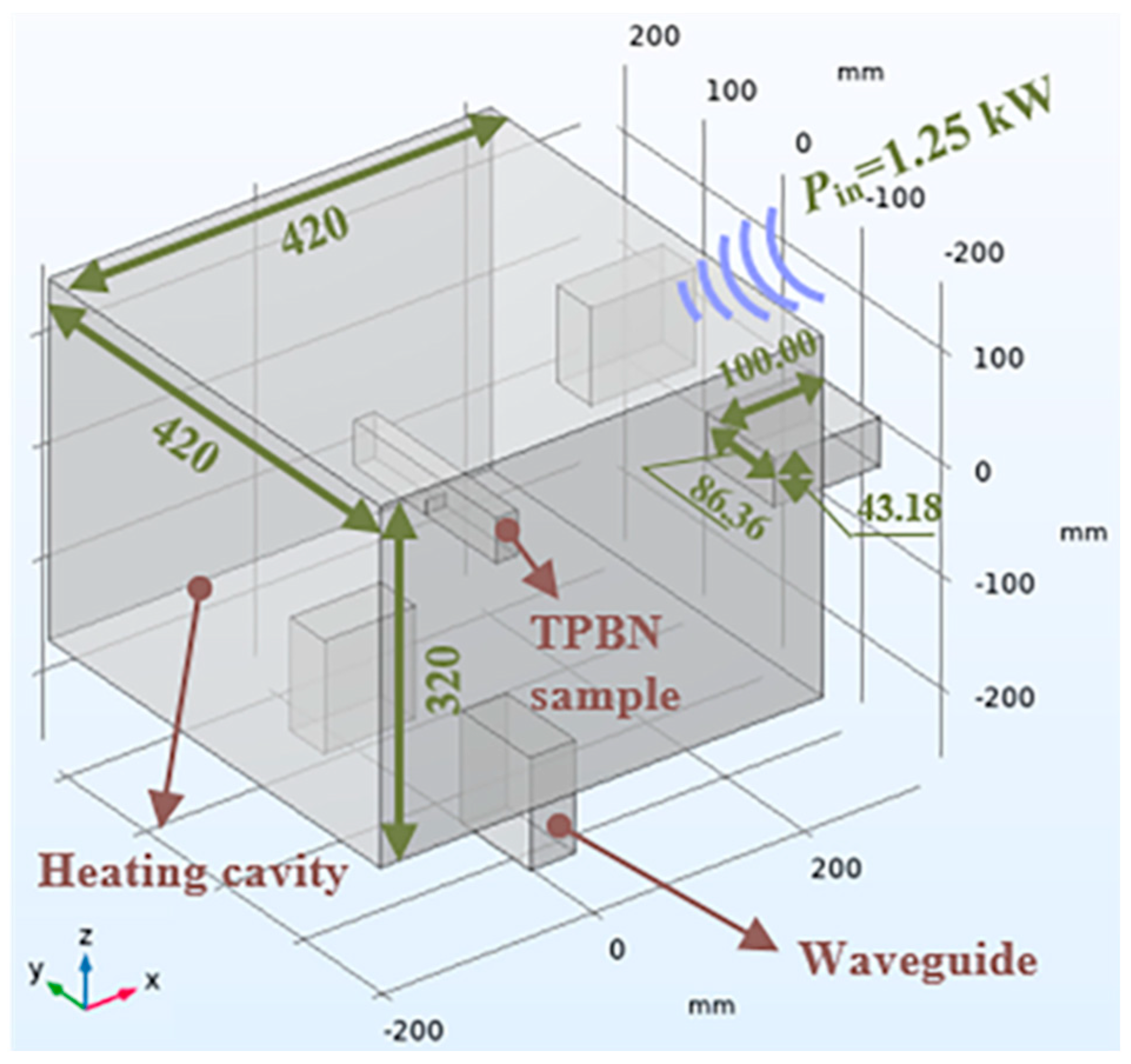
Figure 4.
Specific heat capacity and thermal conductivity of the granite specimen.

Figure 5.
Meshing of the microwave-heated granite model and mesh independence validation.

Figure 6.
Five microwave-heating stages (S1, S2, …, S5) of the granite specimens.

Figure 7.
Distribution of electric field norms in microwave heating cavities and granite.

Figure 8.
Evolution of the temperature field in granite during the microwave-heating process.

Figure 9.
Temperature evolutions adjacent to the top of the initial notch of the granite specimens.

Figure 10.
Failure process of the microwave-heated granite in the TPB tests.

Figure 11.
Load–displacement relationship of the granite specimens after microwave heating ( kW).

Figure 12.
Variation in fracture toughness of the granite specimens under microwave irradiation.

Figure 13.
Evolution of the fracture angle of microwave-heated granite.

Figure 14.
Variations in the penetration depth and power absorption of the granite specimens and their major mineral components.
Figure 14.
Variations in the penetration depth and power absorption of the granite specimens and their major mineral components.

Figure 15.
Establishment of the coupled electromagnetic–thermal–mechanical multiphysics model for microwave-heated granite considering the realistic microstructure.
Figure 15.
Establishment of the coupled electromagnetic–thermal–mechanical multiphysics model for microwave-heated granite considering the realistic microstructure.

Figure 16.
Meshing scheme and the quality of the mineral texture in a coupled electromagnetic–thermal–mechanical model.
Figure 16.
Meshing scheme and the quality of the mineral texture in a coupled electromagnetic–thermal–mechanical model.

Figure 17.
Variation in the specific heat capacity of the minerals with temperature [23].
Figure 17.
Variation in the specific heat capacity of the minerals with temperature [23].

Figure 18.
Temperature evolution near the initial notch tip of the granite specimen in the 2D model ( kW).
Figure 18.
Temperature evolution near the initial notch tip of the granite specimen in the 2D model ( kW).

Figure 19.
Typical paths selected for studying temperature gradient evolution in microwave-heated granite.
Figure 19.
Typical paths selected for studying temperature gradient evolution in microwave-heated granite.

Figure 20.
Evolution of temperature gradient in granite under microwave irradiation along (a) Path 1, (b) Path 2, (c) Path 3, (d) Path 4, and (e) Path 5.
Figure 20.
Evolution of temperature gradient in granite under microwave irradiation along (a) Path 1, (b) Path 2, (c) Path 3, (d) Path 4, and (e) Path 5.

Figure 21.
Evolution of the first principal stress profiles in granite under microwave irradiation along (a) Path 1, (b) Path 2, (c) Path 3, (d) Path 4, and (e) Path 5.
Figure 21.
Evolution of the first principal stress profiles in granite under microwave irradiation along (a) Path 1, (b) Path 2, (c) Path 3, (d) Path 4, and (e) Path 5.


Figure 22.
Variations in the critical thermal stress, fracture toughness, and temperature of the notch tip with the microwave exposure time.
Figure 22.
Variations in the critical thermal stress, fracture toughness, and temperature of the notch tip with the microwave exposure time.

Figure 23.
Evolution of the damage zone near the notch tip of granite under microwave irradiation at (a) 293 °C, (b) 380 °C, (c) 425 °C, (d) 448 °C, and (e) 467 °C.
Figure 23.
Evolution of the damage zone near the notch tip of granite under microwave irradiation at (a) 293 °C, (b) 380 °C, (c) 425 °C, (d) 448 °C, and (e) 467 °C.


Table 1.
Thermal and electric properties of the granite specimen, copper, and air.
| Properties | Value | ||
|---|---|---|---|
| Granite Specimen | Copper | Air | |
| Initial temperature (, °C) | 35 | 35 | 35 |
| Density (, kg/m3) | 2638 | 8960 | - |
| Thermal conductivity (, W/(m·K)) | 400 | - | |
| Specific heat capacity (, J/(kg·K)) | 385 | - | |
| Conductivity (, S/m) | 0 | 5.998 × 10⁷ | 0 |
| Relative permeability (, H/m) | 1 | 1 | 1 |
| Relative permittivity (, F/m) | 1 | 1 | |
Table 2.
Variation in relative permittivity of the granite specimen with temperature.
| Temperature (T, °C) | 35 | 100 | 200 | 300 | 400 | 500 | 600 | 700 | 800 | 900 | 1000 |
|---|---|---|---|---|---|---|---|---|---|---|---|
| Dielectric constant (, F/m) | 5.45 | 5.44 | 5.45 | 5.45 | 5.45 | 5.47 | 5.45 | 5.48 | 5.37 | 5.08 | 5.22 |
| Dielectric loss (, F/m) | 0.038 | 0.033 | 0.037 | 0.043 | 0.052 | 0.076 | 0.118 | 0.210 | 0.175 | 0.135 | 0.319 |
| Mineral | Pl | Qtz | Bt |
|---|---|---|---|
| Dielectric constant (, F/m) | 5.62 | 4.00 | 7.48 |
| Dielectric loss (, F/m) | 0.039 | 7.52 × 10⁻⁴ | 0.456 |
Table 4.
Material properties used as inputs for analyzing temperature gradient and thermal stress [35,38,48].
| Material | Density , kg/m3) | Young’s Modulus , GPa) | Poisson’s Ratio , 1) | Coefficient of Thermal Expansion , 1/K) | Thermal Conductivity , W/(m·K)) |
|---|---|---|---|---|---|
| Granite | 2638 | 60 | 0.25 | 7 × 10⁻⁶ | 2.5 |
| Pl | 2630 | 56.4 | 0.32 | 3.7 × 10⁻⁶ | 2 |
| Qtz | 2650 | 83.1 | 0.07 | 12.1 × 10⁻⁶ | 6.5 |
| Bt | 2800 | 17.2 | 0.36 | 8.3 × 10⁻⁶ | 3 |
Disclaimer/Publisher’s Note: The statements, opinions and data contained in all publications are solely those of the individual author(s) and contributor(s) and not of MDPI and/or the editor(s). MDPI and/or the editor(s) disclaim responsibility for any injury to people or property resulting from any ideas, methods, instructions or products referred to in the content. |
© 2024 by the authors. Licensee MDPI, Basel, Switzerland. This article is an open access article distributed under the terms and conditions of the Creative Commons Attribution (CC BY) license (https://creativecommons.org/licenses/by/4.0/).
Share and Cite
MDPI and ACS Style
Yuan, Y.; Zhao, S. Analysis of Microwave-Induced Damage in Granite Aggregates Influenced by Mineral Texture. Buildings 2024, 14, 1348. https://doi.org/10.3390/buildings14051348
AMA Style
Yuan Y, Zhao S. Analysis of Microwave-Induced Damage in Granite Aggregates Influenced by Mineral Texture. Buildings. 2024; 14(5):1348. https://doi.org/10.3390/buildings14051348
Chicago/Turabian StyleYuan, Yuan, and Shuang Zhao. 2024. "Analysis of Microwave-Induced Damage in Granite Aggregates Influenced by Mineral Texture" Buildings 14, no. 5: 1348. https://doi.org/10.3390/buildings14051348
Note that from the first issue of 2016, this journal uses article numbers instead of page numbers. See further details here.