
A Calculation Method for Reliability Index of a Deep–Bedded Karst Tunnel Construction with Cavity Located Ahead of Tunnel Working Face
1
School of Civil Engineering and Architecture, Guangxi University, Nanning 530004, China
2
School of Civil & Architecture Engineering, East China University of Technology, Nanchang 330013, China
3
School of Architectural Engineering, Guangzhou City Construction College, Guangzhou 510925, China
4
Key Laboratory of Disaster Prevention and Structural Safety of Ministry of Education, Guangxi University, Nanning 530004, China
*
Author to whom correspondence should be addressed.
Buildings 2024, 14(5), 1349; https://doi.org/10.3390/buildings14051349
Submission received: 6 April 2024
/
Revised: 1 May 2024
/
Accepted: 6 May 2024
/
Published: 9 May 2024
(This article belongs to the Section Construction Management, and Computers & Digitization)
Abstract
:For the purpose of reliability quantitative assessment of the surrounding rock of the deeply embedded karst tunnel and the geological body around the cavern in the case of the cavern in the forepart of the tunnel face, on the basis of the upper bound limit analysis method, the energy dissipation theory, as well as the reliability theory, the dimensionless performance function of each damage area of the deeply buried karst tunnels could be established in the case of the cavern in the front of the tunnel face. Subsequently, the probability of failure and the reliability index of each damage region of the deep–bedded karst tunnel in the case of the cavern in the front of this tunnel face should be calculated through the Monte Carlo simulation sampling approach. The investigation has demonstrated that the larger the cohesion of the geotechnical body and the larger the internal friction angle within the geotechnical body, the larger the reliability indexes of the geotechnical bodies around the tunnel. The larger the diameter of the cavern and the larger the tunnel burial depth, the greater the probability of failure in the left part of the geotechnical body around this cavern, and the smaller the reliability indexes of these damage areas.
1. Introduction
Tunnels may be subjected to a large variety of karst caves when tunnelling in karst zones [1]. Under such circumstances, the displacement field and stress field of the tunnel surrounding rock in karst areas, as well as the damage mode of the geotechnical bodies around this tunnel may have different response characteristics with the presence of the karst cave. Through the statistics on the occurrences of geological hazards in tunnels under complex and variable geological conditions, it was discovered that water inrush accidents [2,3] and collapse accidents [4] occurred more frequently in karst regions [5]. The size of the cavern [6], the orientation relationship between the cavern and the tunnel [7], and the clear distance between the cavity and the tunnel [8] could also have a significant impact on the reliability of the tunnel surrounding rock and the rock and soil masses around the karst cave. Therefore, with the introduction of the random field theory and the reliability theory on the basis of limit analysis of the tunnel surrounding rock, a quantitative assessment of the reliability of the disturbed rock and soil body around the deeply buried tunnel when the cavern is located in front of the tunnel face should be proposed, which provides a certain academic reference value for the study of quantitative assessment of the risk of the construction of the deeply buried tunnel in the karst area.
Currently, a number of scholars have applied finite element numerical simulation methods [9,10] as well as the limit analysis method [11,12] to study the response characteristics of the stability of the tunnel surrounding rock during tunnel excavation in karst areas. Ma et al. [13] investigated the effect of the caverns on U–shaped tunnels with different cavern locations and cave shapes by numerical simulation, applying the distinct lattice spring model. Ye et al. [14] proposed an analytical model of the irregular fragment shape of water–rich karst tunnel excavation under the coupling of hydrology and mechanics, and quantitatively analyzed the interactions between the evolution of fracture distribution of the tunnel surrounding rock, the water inrush risk, and the tunnel surrounding rock stress. Shi et al. [15] analyzed the adjacent relations among the tunnels and the cavities, taking into account the spatial decomposition methods within massive cavities, which provided a theoretical basis for the problem of constructing tunnels through large karst caves. From the above, a great number of scholars around the globe have carried out numerous investigations concerning the features of mechanical performance of tunnel engineering in karst areas.
Meanwhile, numerous scholars also conducted risk assessment of karst tunnel engineering through this application of the analytic hierarchy process [16], the attribution recognition model [17], and the multi–factor risk evaluation index system [18]. Kim et al. [19] quantitatively assessed the factors influencing the risk of a tunnel collapsing by applying an analytic hierarchy process and Delphi survey analysis method. However, the hierarchical analysis method has more qualitative components for karst tunnel risk assessment, which is overly dependent on the subjective judgment of humans. With the aim of overcoming this shortcoming, the reliability theory [20,21] and the random field model [22] could be introduced into the system so that the full quantitative assessment of the construction risk of karst tunnels could be carried out. Gan et al. [23] established a deterministic model of the twin tunnels located beneath an existing shield tunnel and conducted simulations through the application of the Monte Carlo method to assess the probability of failure during tunnel deformation when tunnel deformation exceeds the tolerance threshold. Li et al. [24] developed a damage model for tunnel excavation in double–layered soils under a theoretical basis of ultimate analysis to characterize the probability of failure of the tunnel working surface using an active learning Kriging model. Cheng et al. [25] investigated the failure mechanism of autocorrelation distance on the tunnel excavation face under multilayer soil conditions with the stochastic limit analysis. In summary, in the present situation of research on the application of the reliability theory, there are relatively few research results concerning the reliability analysis for geotechnical blocks around karst tunnels.
Wu et al. [26] developed a reliability assessment algorithm for deep tunnels which analyzed and predicted the time–dependent reliability of the excavation process of the deeply buried tunnel. Cai et al. [27] calculated the complex ground stress through physical model experiments and three–dimensional numerical simulation and researched the non–linear mechanical and strength characteristics of the tunnel excavation in different burial depth rock strata. Kong et al. [28] investigated the collapsing properties of the initial supporting lateral walls of the deeply burial railway tunnels with laboratory tests and numerical simulations. Considering the above research situation of the mechanical characteristics and the reliability research of deeply buried tunnels, fewer research results have been derived from the theoretical solution for the reliability of deep tunnel construction.
Consequently, through the summary and analysis of previous research results, the research literature on the analysis of the mechanical characteristics of tunnel construction in karst areas is relatively widespread; however, the research literature on the stability of tunnel construction in karst areas in combination with reliability theory has been relatively uncommon. In previous research, deterministic results were obtained for the analysis of mechanical properties of construction in karst areas. In view of the current research basis, a reliability analysis method for the surrounding rock of karst deeply buried tunnels and the rock and soil bodies around the caverns considering the spatial variability of the parameters of the rock and soil masses could be established by introducing the random field theory and the Monte Carlo sampling simulation method. The study will lay a conceptual foundation for the safety of deeply buried karst tunnel construction with cavities located ahead of such tunnel working surfaces.
Firstly, on the basis of the upper bound limit analysis theorem [29] and dissipative structure theory, the failure mode for deeply embedded karst tunnels could be proposed with cavities located ahead of the tunnel working surface. With the introduction of random field theory and reliability theory [30], the probability of failure and reliability indexes of each damage region of the karst tunnel with cavities located ahead of the tunnel working surface are computed with a Monte Carlo method of simulated sampling.
Secondly, the rationality and validity of the calculation method of the probability of failure and the reliability index of karst tunnel construction should be verified when the cavern is situated ahead of the tunnel working surface with the comparison and analysis with the strength reduction method.
Thirdly, the analytical solution for calculating the probability of failure and the reliability index of karst tunnel engineering with cavities located ahead of the tunnel working surface could be applied to practical engineering. The study could analyze the quantitative assessment of the influencing factors [31] on the construction safety and reliability of these deeply buried karst tunnels.
A list of explanations of the signs mentioned in this paper is shown in Table 1.
2. Damage Modelling and Reliability Calculation Method
As indicated by the test results in [32], Protodyakonov’s theory is only applicable to rectangular or gently vaulted tunnels with stable surrounding rocks and tunnels that are not too deep. Therefore, energy dissipation theory is being introduced such that the process of energy exchange between the internal part of the deeply buried tunnel system and the external environment is more sufficiently represented when the cavern is ahead of the tunnel working surface. Energy dissipation in the deeply embedded tunnels is the exchange of energy between the tunnel system and its associated environment. When tunnelling in the complicated conditions in geotechnical formations, the original equilibrium state of the geotechnical strata could be extremely vulnerable to disruption with the action of high ground stress. In accordance with the distance from cave to tunnel, this damage region of the tunnel surrounding rock and this damage region of rockmass surrounding the cavern present the three states in Figure 1a–c, respectively. When the cavern is empty, the tunnel construction failure mode is proposed with cavities located ahead of the tunnel working surface. The damage region consists of the A–1 damage region, the A–2 damage region, the A–3 damage region, and the A–4 damage region.
The A–1 damage region consists of m–2 triangular blocks , m–2 triangular blocks , , and . The A–2 damage region consists of m–1 triangular blocks and .
The A–3 damage region consists of m–2 triangular blocks , m–2 triangular blocks , , and . The left–hand part of the A–4 damage region consists of m–1 triangular block , as well as the polygonal block . What is more, the right–hand part of the A–4 damage region consists of m–1 triangular block , as well as the polygonal block .
As a consequence of the complex diversity of cavities in karst regions, with the aim of making it simpler and more feasible to study the stability of deeply buried karst tunnelling when this cavern is ahead of the tunnel working surface, a methodology for the study of this stability of deeply buried karst tunneling would be developed. The cavity should be in a simplified circular shape in this two–dimensional tunnel damage model. This damage model for this deeply buried karst tunnel could be optimally analyzed by applying a plane strain model. Therefore, the essential hypotheses of this deeply buried karst tunnel should be as follows:
- (1)
- It is assumed that the Mohr–Coulomb strength theory should be applicable to the geotechnical materials in this construction damage model for deeply buried karst tunnels.As the geotechnical body in this damage model is subjected to yielding, the geotechnical body should obey the associated flow rule.
- (2)
- It is assumed that the tunnel depth is , the cavern depth is , the tunnel diameter is , the cave diameter is . The cohesion of the geotechnical body is c, the friction angle of the geotechnical body is , and the gravity of the geotechnical body is .
- (3)
- The cavern in this failure model is an empty karst cave.
- (4)
- The assumption is that the physical property indices of the rockmass in this failure model should conform to a Gaussian distribution.
- (5)
- It is assumed that the geometrical deformation of the geotechnical body in the deeply buried karst tunnel model at the moment of damage would be small.
2.1. Velocity Field
After establishing the damage models of the karst deeply buried tunnel construction when the cavern is located in front of the tunnel building working face, it is also necessary to establish the velocity field of the four damage areas, including the A–1 region, the A–2 region, the A–3 region, and the A–4 region, within the karst deeply buried tunnel construction damage model.
In the basic assumptions, the plastic deformation of the geotechnical body conforms to the associated flow rule, and the angle between the velocity vector of the blocks and the rigid boundary of the velocity discontinuity [33] is , as illustrated in Figure 2a,b. The velocity of the triangular block is . The expressions for the velocities of the velocity discontinuities and are the expressions (1) and (2), respectively. A large number of abbreviations will be covered in the following section, and a table explaining the abbreviations will be placed at the end of the paper in the form of an appendix, as shown in Table A1 in Appendix A.
where —the velocity of the velocity discontinuity , and —the velocity of the velocity discontinuity .
The expressions for the velocities of the velocity discontinuities as well as are expressions (3) and (4), respectively.
where —the velocity of the velocity discontinuities , and —the velocity of the velocity discontinuities .
The expression for the velocity of the velocity discontinuity is expression (5).
where —the velocity of the velocity discontinuity .
The expressions for the velocities of the velocity discontinuities as well as are expressions (6) and (7), respectively.
where —the velocity of the velocity discontinuity , and —the velocity of the velocity discontinuity .
The expressions for the velocities of the velocity discontinuities as well as are expressions (8) and (9), respectively.
where —the velocity of the velocity discontinuities , and —the velocity of the velocity discontinuities .
The expression for the velocity of the velocity discontinuity is expression (10).
where —the velocity of the velocity discontinuity .
In Figure 2c,d, the velocity of triangular block is . The expressions for the velocities of the velocity discontinuities and in region A–2 are expressions (11) as well as (12), respectively.
where —the velocity of the velocity discontinuities , and —the velocity of the velocity discontinuities .
The expressions for the velocities of the velocity discontinuities as well as are expressions (13) and (14), respectively.
where —the velocity of the velocity discontinuity , and —the velocity of the velocity discontinuity .
In Figure 3a,b, the velocity of triangle mass is . The expressions for the velocities of the velocity discontinuities as well as in the A–3 failure region are expressions (15) and (16), respectively.
where —the velocity of the velocity discontinuity , and –the velocity of the velocity discontinuity .
The expressions for the velocities of the velocity discontinuities as well as are expressions (17) and (18), respectively.
where —the velocity of the velocity discontinuities , and —the velocity of the velocity discontinuities .
The expression for the velocity of the velocity discontinuity is expression (19).
where —the velocity of the velocity discontinuity .
In Figure 3c,d, the velocity of a polygonal mass is . The expressions for the velocities [34] of the velocity discontinuities as well as in the A–4 failure region are expressions (20) as well as (21), respectively.
where —the velocity of the velocity discontinuity , and —the velocity of the velocity discontinuity .
The expressions for the velocities of the velocity discontinuities as well as in the A–4 failure region are expressions (22) and (23), respectively.
where —the velocity of the velocity discontinuities , and —the velocity of the velocity discontinuities .
2.2. Energy Dissipation Rate
Upon constructing the velocity field of each damage region in the damage models for deeply buried karst tunnel construction in such karst regions, the product of the velocity of each velocity discontinuity line and its length could be the value of the energy dissipation rate of each velocity discontinuity line. In Figure 2a,b, the expression for the rate of energy dissipation in velocity discontinuities , as well as in region A–1 is presented by expression (24).
where —the rate of energy dissipation in velocity discontinuities , as well as .
The expression for the rate of energy dissipation in velocity discontinuities , as well as in the A–1 region is presented by expression (25).
where —the rate of energy dissipation in velocity discontinuities , as well as .
In Figure 2c,d, the expression for the rate of energy dissipation in velocity discontinuities as well as in region A–2 is presented by expression (26).
where —the rate of energy dissipation in velocity discontinuities as well as .
The expression for the rate of energy dissipation in velocity discontinuities and in region A–2 is presented by expression (27).
where —the rate of energy dissipation in velocity discontinuities and .
In Figure 3a,b, the expression for the rate of energy dissipation in velocity discontinuities , and in region A–3 is presented by expression (28).
where —the rate of energy dissipation in velocity discontinuities , and .
In Figure 3c,d, the expression for the rate of energy dissipation in velocity discontinuity in region A–4 is presented by expression (29).
where —the rate of energy dissipation in velocity discontinuity .
The expression for the rate of energy dissipation in velocity discontinuities and in region A–4 is presented by expression (30).
where —the rate of energy dissipation in velocity discontinuities and .
2.3. Power of External Work
The external power of each block in this karst deep tunnel construction model under self–weight is obtained by multiplying the area of the block with its self–weight. In Figure 2a,b, the expression of the external power of the triangle masses , and at their self–weight is presented by expression (31).
where —the external power of the triangle masses , and , are the area of the triangle block , are the area of the triangle block , are the area of the triangle block .
The expression of the external power of the triangle masses as well as at their self–weight is presented by expression (32).
where —the external power of the triangle masses as well as , is the triangular mass area, is the triangular bulk area.
In Figure 2c,d, the expression of the external power of the triangle bulk at its self-weight is presented by expression (33).
where —the external power of the triangle bulk , and is the triangular mass size.
The expression of the external power of the triangle bulk at their self-weight is presented by expression (34).
where —the external power of the triangle bulk , and is the triangular bulk size.
In Figure 3a,b, the expression of the external power of the triangle bulk at its self-weight is presented by expression (35).
where —the external power of the triangle bulk , and is the size of the triangular bulk .
The expression of the external power of the triangle mass at its self-weight is presented by expression (36).
where —the external power of the triangle mass , is the size of the triangular bulk , is the size of the triangular bulk .
In Figure 3c,d, the expression of the external power of the polygonal mass at its self-weight is presented by expression (37).
where —the external power of the polygonal mass , and is the polygonal bulk size.
The expression of the external power of the triangle mass at its self-weight is put forward by expression (38).
where —the external power of the triangle mass , and is the triangular mass size.
Thus, the geometrically constrained expressions of zone A–1 are expressions (39).
Consequently, the geometrically constrained expressions of zone A–2 are expressions (40).
Hence the geometrically constrained expressions of zone A–3 are expressions (41).
Therefore, the geometrically constrained expressions of zone A–4 are expressions (42).
2.4. Performance Functions
Following the derivation of the power expression of the external work done by the self-weight of each polygonal block in the damage model of the karst deeply buried tunnel when the cavern is located in front of the tunnel building working face and the expression of the energy dissipation rate on the velocity discontinuity line, based on the reliability theory, the performance function of the damage regions of the karst deeply buried tunnel could be constructed.
The damage regions in the construction failure mode for the karst tunnels intersect as the cavern-tunnel spacing decreases. Therefore, the distribution coefficient should be introduced because the energy dissipation rate of each damage region and the power of the external power by its own weight should be appropriately distributed in accordance with the actual situation. The expression for the performance function of this rockmass for zone A–1 as well as zone A–2 is:
where is the performance functional expression of zone A–1 and zone A–2, is the distribution coefficient for the rate of power dissipation in zone A–1, the range of values of is , is the distribution coefficient for the rate of power dissipation in zone A–2, the range of values of is , is the distribution coefficient of the power of external work by its own weight in zone A–1, the range of values of is , is the distribution coefficient of the power of external work by its own weight in zone A–2, the range of values of is .
Illustrated in Figure 1, since the left part of the cavern is closer to the tunnel excavated surface of the deeply buried karst tunnel than the right part of the cavern, the geotechnical body at the left part of the karst cave should be paid more attention than the geotechnical body at the right part of the cavern. As a result, it is only necessary to establish the performance functions of the geotechnical body at the left part of the more hazardous cavity. A performance functional expression of the rockmass of the left part of region A–3 and the left part of zone A–4 is:
where is the performance function of the left part of zone A–3 as well as the left side of zone A–4, is the distribution coefficient for the rate of power dissipation in zone A–3, the range of values of is , is the distribution coefficient for the rate of power dissipation in zone A–4, the range of values of is , is the distribution coefficient of the power of the power of external work by its own weight in zone A–3, the range of values of is . is the distribution coefficient of the power of external work by its own weight in zone A–4, and the range of values of is .
Based on reliability theory and with the introduction of a random field model, the randomness of the engineering parameters of the physical mechanical property indicators of the geotechnical body should be under consideration, and by applying the Monte Carlo simulation method, the probability of failure and the reliable parameter of each damage area of karst tunnel engineering could be calculated with cavities located ahead of the tunnel working surface.
The failure probability expression in zone A–1 as well as zone A–2 is put forward by:
where —the probability of failure in zone A–1 as well as zone A–2, and b is the threshold quantity used to identify if the zone is destroyed or not.
The failure probability expression at the left part of zone A–3 as well as the left part of zone A–4 is put forward by:
where —the probability of failure at the left part of zone A–3 as well as the left part of zone A–4, and b is the threshold quantity used to identify if the zone is destroyed or not.
The reliability index expression of zone A–1 as well as zone A–2 is put forward by:
where —the reliability index of zone A–1 as well as zone A–2.
The reliability index expression of zone A–3 as well as zone A–4 is put forward by:
where —the reliability index of zone A–3 as well as zone A–4.
3. Comparison and Verification
In order to comparatively verify the reasonableness and validity of the methodology for calculating the probability of destabilization in deep tunnel engineering with cavities located ahead of the tunnel working surface, firstly, the three-dimensional numerical simulation of deep tunnelling in the case of caverns ahead of the tunnel working surface should be carried out, and the dynamic states of the plastic strain diagrams at several typical excavation steps in close proximity to the karst cave should be comparatively analyzed. Secondly, two-dimensional numerical simulations of deep tunnel excavation should be implemented in the case of caverns ahead of the tunnel working surface, and these safety factors of the deep tunnel excavation modellings should be calculated by applying strength reduction theory with finite element. Thirdly, the performance functions of region A–1 as well as region A–2 of the deeply buried tunnel construction in the case of caverns ahead of the tunnel working surface should be constructed. Additionally, the Monte Carlo simulation methodology should be implemented to compute the probability of failure in deep tunnelling in the case of caverns ahead of the tunnel working surface. According to the conversion relationship between the probability of failure, the reliability index, and the factor of safety, the factors of safety of zone A–1 and zone A–2 in deep tunnelling in the case of caverns ahead of the tunnel working surface should be calculated.
As shown in Figure 4a, the three-dimensional numerical simulation of deep tunnelling in the case of caverns ahead of the tunnel working surface is for a length of 50 m, a width of 67 m, and a height of 97 m. The depth of the tunnel is 50 m and the tunnel diameter is 6.7 m. The tunnel will be constructed through the shield method, with the shield tunnel segment width of 1.0 m. The outer as well as inner diameters of the shield tunnel segment are 6.7 m and 6 m, respectively. The cavern, which has a diameter of 3 m, is located 40 m from the tunnel entrance. These numerical simulation models were established with the application of ABAQUS 2019 version, a large-scale finite element analysis software developed by Dassault Systèmes in France.
The parameters of physics characteristics of the weathered dolomite strata of an underground section engineering could be taken in three–dimensional numerical simulation modelling, two-dimensional numerical simulation modelling, as well as two-dimensional analytical solution modelling for deep tunnel excavation, illustrated in Table 2. The magnitude of the uncertainty in the parameters of the ground media properties could result from the granular composition of the geotechnical body and its spatial distribution pattern, and could also be associated with the influence of factors such as the time-varying nature of the tunnelling disturbances.
In Figure 4b, the equivalent plastic strain map by the application of the strength deduction theory is shown for deep tunnelling in the case of caverns ahead of the tunnel working surface. The plastic strain region could be concentrated in the zone of the tunnel boring surface and the zone of the geotechnical body surrounding the cavern, which also extends upwards and to the earth’s surface. Figure 4c draws the strain curves of the deeply buried karst tunnel at excavation step 30, excavation step 35, and excavation step 40 in case of caverns ahead of the tunnel working surface. The tunnel vault strain at the 40th excavation step in tunnel excavation was 46.25% greater than that at the 30th excavation step in tunnel excavation. The left haunch strain of the deeply buried karst tunnel at the 40th excavation step was 17.58% greater than that at the 35th excavation step. The tunnel arch bottom strain at excavation step 40 of the tunnelling was 46.37% greater than that at excavation step 30 of the tunnelling. The above comparative analysis shows that the strain at the measurement points in the tunnel cross-section at excavation step 40 have a remarkable enlargement compared to excavation step 30 and excavation step 35. This demonstrates that it is necessary to study the key issue of safety risks in deep tunnelling in the case of caverns ahead of the tunnel working surface [35].
As shown in Figure 4d, when the clearance from the tunnel to the cavity is 3 m, and the cohesion within the geotechnical body is 800 kPa, the safety factor obtained by using the analytical solution method of calculating the probability of failure as well as the reliability index of this deeply buried karst tunnel is 16.12% smaller than the value obtained using the strength reduction theory with finite element. When the clearance from the tunnel to the cavity is 8 m, and the cohesion within the geotechnical body is 800 kPa, the safety factor obtained by using the analytical solution method of calculating the probability of failure as well as the reliability index of this deeply buried karst tunnel is 27.13% smaller than the value obtained using the strength reduction theory with finite element. In conclusion, in comparison with the factor of safety calculated according to the strength reduction theory with finite element, the factor of safety calculated according to the analytical solution method of calculating the probability of failure as well as the reliability index of this deeply buried karst tunnel could also be within a reasonable range.
4. Application of Engineering
4.1. Information on the Project
With the validity and reasonableness of this calculation method of the instability probability and the reliability index for karst deeply buried tunnel construction verified, this method of calculating reliability index for karst deeply buried tunnel construction could be applied in engineering practice.
Part of a metro interval project consists of a shield tunnel, which passes through a karst area with strong development of a karst cave. As a consequence of the randomness of the formation process of geological formations, the spatial relationship of the cavity and the tunnel during the tunnel boring process also presents randomness. Therefore, this situation of the cavern ahead of the tunnel working surface could also be extremely possible. The tunnel in the karst zone is constructed with the shield method, and this segment of the interval tunnel mainly goes across the moderately weathered dolomite formation. The size of the cavity space [36] in this subway interval section ranged from 3.5 m to 5.1 m. As a consequence, the engineering geological parameters for the segment of the interval tunnel could adopt the physical property index engineering variables for the moderately weathered dolomite [37] from the field engineering investigation results, as indicated in Table 2. The geological profile of this urban rail transit project is shown in Figure 5.
4.2. Effect of Internal Friction Angle
The criterion applied to rank the likelihood of occurrence of the risk probability is the code for risk management of underground works in urban rail transit (GB50652-2011) [38], which was developed by the ministry of housing and urban–rural development of the People’s Republic of China. The qualitative assessment of the likelihood of risk corresponds to the quantitative calculation of the probability of risk, when the value of the probability of occurrence of the risk of the construction of underground works for urban rail transport is greater than 10%. Correspondingly, in the case of a high number of accidents in tunnelling, the likelihood of occurrence of the risk can be qualitatively assessed as “frequent”, and the likelihood of occurrence of this event is classified as level 1. Apart from that, when the probability of occurrence of risks in the construction of underground urban railways is 1–10%, the number of accidents in tunnelling is not too high, and the likelihood of occurrence of risks is qualitatively assessed as “probable”, then the likelihood of occurrence of risks in this case is classified as level 2.
As shown in Figure 6a,b, if the cohesion of the rockmass is 1000 kPa, what is more, the internal friction angle is 42°, and the cavern is an empty karst cave, the probability of failure in zone A–1 and zone A–2 is 8.53%, and the reliability index of the geotechnical masses around the tunnel is 1.37. Furthermore, the likelihood level of a hazard occurring of the geotechnical masses around the tunnel [39] is level 1. When the cohesion of the geotechnical body is 500 kPa, the internal friction angle is 42°, and in addition, there is no filling of the a cave, and the probability of failure in zone A–1 and zone A–2 is 13.13%. Furthermore, the reliability index of zone A–1 and zone A–2 is 1.12. Therefore, the likelihood level of a hazard occurring of the geotechnical masses around the tunnel is ranked as level 2. The difference between the probability of failure in zone A–1 and zone A–2 in the former case and the latter case is 4.60%, and the reliability indexes in the A–1 region and the A–2 region in the former case are 18.25% greater than those in the latter case.
When the cohesion of the geotechnical body is 1000 kPa, the angle of internal friction is 50°, and the cavern is an empty karst cave, the instability probability of the A–1 area and the A–2 area is 3.69%, the reliability index of zone A–1 and zone A–2 is 1.79. Moreover, the likelihood level of a hazard occurring of zone A–1 and zone A–2 is ranked as level 1. When the cohesion of the geotechnical body is 1000 kPa, the angle of internal friction is 45°, and the cavern is an empty karst cave, the instability probability of the A–1 area and the A–2 area is 5.24%, the reliability index of the A–1 area and the A–2 area is 1.62, and the risk occurrence possibility level of the A–1 area and the A–2 area is ranked as level 1. The difference between probability of failure in zone A–1 and zone A–2 in the former case and the latter case is 1.55%, and the reliability index in the A–1 region and the A–2 region in the former case are 9.50% greater than those in the latter case. Consequently, when the cohesion of the geotechnical body is 1000 kPa, the karst cave is empty, the internal friction angle varies from 40° to 50°, and the risk occurrence possibility level of the A–1 area and the A–2 area is level 1. In conclusion, the larger the geotechnical body cohesion, the larger the internal friction angle within the geotechnical masses, the smaller the instability probability of region A–1 as well as region A–2, the larger the reliability index of the damage regions.
When the cohesion of the geotechnical body is 1000 kPa, the internal friction angle is 50°, and there is no filling of the cavity; the instability probability for the left part of zone A–3 as well as the left part of zone A–4 is 8.24%, the reliability index for the left part of zone A–3 as well as the left part of zone A–4 is 1.39, and the risk occurrence possibility level of the left part of zone A–3 as well as the left part of zone A–4 is level 1, illustrated in Figure 7a,b. When the cohesion of the geotechnical body is 1000 kPa, what is more, the angle of internal friction is 42°, there is no filling of the a cavity, the probability of failure of the left part of the A–3 area and the left side of the A–4 area is 13.47%, and the reliability index of the left side of the A–3 area and the left side of the A–4 area is 1.10. In addition, the likelihood level of a hazard occurring of the left side of the A–3 area and the left side of the A–4 area is classified as level 2.
The difference between the instability probability in the left part of zone A–3 and the left part of zone A–4 in the former case and the latter case is 5.23%, and the reliability indexes in the left part of zone A–3 and the left part of zone A–4 in the former case are 20.86% greater than those in the latter case. Therefore, it is evident that the greater the cohesion of the geotechnical body, the greater the internal friction angle on the rock and soil mass around the cavern, the smaller the instability probability of the left part of zone A–3 and the left part of zone A–4, the greater the reliability index of the failure regions, and the better the stability of the unsteady regions.
4.3. Tunnel Diameter upon the Circumference of the Tunnel
When the tunnel diameter is 6.7 m, the tunnel [40] buried depth is 60 m, and the cavern is an empty karst cave, the instability probability in the A–1 area and the A–2 area is 6.53%, the reliability index of the A–1 area and the A–2 area is 1.51, and the risk occurrence possibility level of the A–1 area and the A–2 area is level 1, illustrated in Figure 8a,b. When the tunnel diameter is 6.7 m, the tunnel buried depth is 120 m, and furthermore, there is no filling of the a cavity, the instability probability in the A–1 area and the A–2 area is 9.23%, the reliability index of the A–1 area and the A–2 area is 1.33, and the risk occurrence possibility level of the A–1 area and the A–2 area is still level 1.
The difference between the probability of failure in zone A–1 and zone A–2 in the former case and the latter case is 2.70%, and the reliability indexes in the A–1 region and the A–2 region in the former case are 11.92% greater than those in the latter case. When the diameter of the tunnel is 8 m, the tunnel buried depth is 100 m, and there is no filling of the a cave, the probability of failure in area A–1 and area A–2 is 8.30%, the reliability index of the A–1 zone and the A–2 zone is 1.38, and the risk occurrence possibility level in the A–1 zone and the A–2 zone is level 1.
When the tunnel diameter is 14 m, the tunnel buried depth is 100 m, apart from that, the a cavern is an empty karst cave, the probability of failure in area A–1 and area A–2 is 10.85%, the reliability index of the A–1 zone and the A–2 zone is 1.23, and the risk occurrence possibility level in the A–1 zone and the A–2 zone is level 1. The difference between the probability of failure in area A–1 and area A–2 in the former case and the latter case is 2.55%, and the reliability indexes in the A–1 region and the A–2 region in the former case are 10.87% greater than those in the latter case. In summary, the greater the tunnel buried depth, and the larger the diameter of tunnel, the greater the probability of failure in area A–1 and area A–2; moreover, the smaller the reliability index of these damage regions.
4.4. Cavity Diameter on The Geotechnical Bodies around Such Cavity
When the tunnel buried depth is 60 m, what is more, the cavity diameter is 5 m, and additionally, the cavern is an empty karst cave, the instability probability of the left side of the A–3 area and the left side of the A–4 area is 9.69%, and the reliability index of the left side of the A–3 area and the left side of the A–4 area is 1.30, and the likelihood level of the hazard occurring for the left part of area A–3 and the left part of area A–4 is level 1, illustrated in Figure 9a,b.
As the tunnel buried depth is 100 m, the cavity diameter is 5 m, and there is no filling of the a cavity, the probability of instability of the left part of area A–3 and the left part of area A–4 is 11.48%, the reliability index of the left part of area A–3 and the left part of area A–4 is 1.20, and the risk occurrence possibility level of the left part of area A–3 and the left part of area A–4 is ranked as level 2.
The difference between the instability probability in the left part of area A–3 as well as the left part of area A–4 in the former case and the latter case is 1.79%, and the reliability indexes in the left part of area A–3 as well as the left part of area A–4 in the former case are 7.69% greater than those in the latter case. Nevertheless, when the tunnel buried depth is 120 m, and the cavity diameter is taken between 3 and 8 m, the instability probability is greater than 10% for both the left side of the A–3 area and the left side of the A–4 area, and as a consequence, the risk occurrence possibility level for both the left side of the A–3 area and the left side of the A–4 area is ranked as level 2. Therefore, it could be seen that the greater the tunnel buried depth, and the larger the cavity diameter, the greater the probability of instability of the left part of area A–3 and the left part of area A–4, the smaller the reliability index of these damage areas, and the worse the stability of these damage areas.
5. Conclusions
With the purpose of quantitative assessment of construction hazards in the surrounding rocks for deep tunnels as well as the geotechnical body around the cavity in deep tunnelling in the case of caverns ahead of the tunnel working surface, a failure mode for karst tunnels with large burial depths in the case of caverns ahead of the tunnel working surface could be proposed through the application of the principle of limit analysis and the theory of energy dissipation. With the introduction of the random field theory and the reliability theory, which take into account the spatial variability of the parameters of the physical properties of the geotechnical bodies, the probability of failure and the reliability index for each damage region of the karst tunnels with large burial depths in the case of caverns ahead of the tunnel working surface could be calculated by applying the sampling method for Monte Carlo simulation. In addition, the impact of the parameters that include the internal friction angle, the diameter of the tunnel, as well as the cavity diameter on the reliability of tunnel engineering in karst areas with deeply buried depths has been studied and analyzed. This research work could supply the necessary support for the reliability assessment of deeply buried tunnel construction when the cavern is located in front of the tunnel working face, as well as provide a favorable theoretical basis for the structural reliability design of deeply buried karst tunnels with consideration of the uncertainty of the material properties.
The conclusions from this research are the following:
- (1)
- In contrast to the coefficient of safety calculated with the strength reduction theory with finite element, the coefficient of safety calculated by this analytical solution method for calculating the probability of instability as well as the reliability index of this deeply buried karst tunnel could be within a reasonable range.
- (2)
- When the cohesion of the geotechnical body is 1000 kPa, the karst cave is empty, and the internal friction angle varies from 42° to 50°, respectively, the reliability index of zone A–1 and zone A–2 is 1.37, 1.79, respectively. And the reliability indexes in the left part of zone A–3 and the left part of zone A–4 in the former case are 20.86% greater than those in the latter case. And the larger the cohesion of the geotechnical body, the larger the angle of internal friction in the body of the rock and soil, the larger the reliability index of area A–1 and area A–2.
- (3)
- When the cohesion of the geotechnical body is 1000 kPa, the internal friction angle is 50° and 42°, respectively, and there is no filling of the cavity, the reliability indexes in the left part of zone A–3 and the left part of zone A–4 in the former case are 20.86% greater than those in the latter case. Hence, the greater the cohesion of the geotechnical body, the greater the internal friction angle on the rock and soil mass around the cavern, the greater the reliability index of the left part of zone A–3 and the left part of zone A–4.
- (4)
- The greater the cohesion of the rockmass, and the greater the angle of internal friction within the geotechnical body, the greater the reliability index of the left part of area A–3 and the left part of area A–4. Additionally, the greater the tunnel buried depth, and the larger the cavern diameter, the greater the probability of instability of the left part of area A–3 and the left part of area A–4, and as a consequence, the smaller the reliability index of these damage areas.
Author Contributions
Conceptualization, B.W. and W.S.; Methodology, B.W. and W.S.; Writing—original draft, W.S.; Writing—review and editing, B.W. and G.M.; Supervision, B.W. All authors have read and agreed to the published version of the manuscript.
Funding
This work was supported by the National Natural Science Foundation of China (Nos. 52278397, 52168055); the Jiangxi Natural Science Foundation Program (No. 20212ACB204001). The financial support is gratefully acknowledged.
Data Availability Statement
The authors confirm that the data supporting the findings of this study are available within the article.
Acknowledgments
The authors thank the reviewers for their great help on the article during its review progress.
Conflicts of Interest
The authors declare no conflicts of interest.
Appendix A

Table A1.
Explanation table for the abbreviations.
| Sign | Meaning | Sign | Meaning |
|---|---|---|---|
| the rate of energy dissipation in velocity discontinuities | |||
| the rate of energy dissipation in velocity discontinuities | |||
| the rate of energy dissipation in velocity discontinuities | |||
| the rate of energy dissipation in velocity discontinuities | |||
| the rate of energy dissipation in velocity discontinuities | |||
| the rate of energy dissipation in velocity discontinuities | |||
| the external power of the triangle masses | |||
| size | |||
| area | the triangular bulk area | ||
| size | . | ||
| size | the triangular mass size | ||
| the performance functional expression of zone A–1 and zone A–2 | |||
| the distribution coefficient for the rate of power dissipation in zone A–1 | |||
| the distribution coefficient for the rate of power dissipation in zone A–2 | |||
| the distribution coefficient of the power of external work by own weight in zone A–1 | |||
| the distribution coefficient of the power of external work by own weight in zone A–2 | |||
| the performance function of the left part of zone A–3 as well as the left side of zone A–4 | |||
| the distribution coefficient for the rate of power dissipation in zone A–3 | |||
| the distribution coefficient for the rate of power dissipation in zone A–4 | |||
| the distribution coefficient of the power of the power of external work by own weight in zone A–3 | |||
| the distribution coefficient of the power of external work by own weight in zone A–4 | |||
| the probability of failure in zone A–1 as well as zone A–2 | the probability of failure at the left part of zone A–3 as well as the left part of zone A–4 | ||
| b | the threshold quantity used to identify if the zone is destroyed or not | ||
| the reliability index of zone A–1 as well as zone A–2 | the reliability index of zone A–3 as well as zone A–4 | ||
References
- Zheng, Y.; He, S.; Yu, Y.; Zheng, J.; Zhu, Y.; Liu, T. Characteristics, challenges and countermeasures of giant karst cave: A case study of Yujingshan tunnel in high-speed railway. Tunn. Undergr. Space Technol. 2021, 114, 103988. [Google Scholar] [CrossRef]
- Huang, M.; Li, J.; Yang, Z.; Zhang, Z.; Song, Y. Analysis and Application of Lining Resistance to Water Pressure in Tunnel through Karst Cave. Appl. Sci. 2022, 12, 7605. [Google Scholar] [CrossRef]
- Wang, Y.; Chen, F.; Yin, X.; Geng, F. Study on the risk assessment of water inrush in karst tunnels based on intuitionistic fuzzy theory. Geomat. Nat. Haz. Risk 2019, 10, 1070–1083. [Google Scholar] [CrossRef]
- Zhu, Y.; Zhou, J.; Zhang, B.; Wang, H.; Huang, M. Statistical analysis of major tunnel construction accidents in China from 2010 to 2020. Tunn. Undergr. Space Technol. 2022, 124, 104460. [Google Scholar] [CrossRef]
- Wang, X.; Lai, J.; Qiu, J.; Xu, W.; Wang, L.; Luo, Y. Geohazards, reflection and challenges in Mountain tunnel construction of China: A data collection from 2002 to 2018. Geomat. Nat. Haz. Risk 2020, 11, 766–784. [Google Scholar] [CrossRef]
- Zhang, L.; Fu, H.; Wu, J.; Zhang, X.; Zhao, D. Effects of Karst Cave Shape on the Stability and Minimum Safety Thickness of Tunnel Surrounding Rock. Int. J. Geomech. 2021, 21, 04021150. [Google Scholar] [CrossRef]
- Xu, Z.; Lin, P.; Xing, H.; Pan, D.; Huang, X. Hydro-mechanical Coupling Response Behaviors in Tunnel Subjected to a Water-Filled Karst Cave. Rock Mech. Rock Eng. 2021, 54, 3737–3756. [Google Scholar] [CrossRef]
- Wu, W.; Liu, X.; Guo, J.; Sun, F.; Huang, X.; Zhu, Z. Upper limit analysis of stability of the water-resistant rock mass of a karst tunnel face considering the seepage force. Bull. Eng. Geol. Environ. 2021, 80, 5813–5830. [Google Scholar] [CrossRef]
- Han, G.; Xue, P.; Wang, Y.; Li, X.; Bian, H.; Wang, Y.; Guo, P. Mechanical Response Law and Parameter Influence Analysis of Karst Tunnel Dynamic Excavation. Appl. Sci. 2023, 13, 9351. [Google Scholar] [CrossRef]
- Li, S.; Wu, J.; Xu, Z.; Zhou, L.; Zhang, B. A possible prediction method to determine the top concealed karst cave based on displacement monitoring during tunnel construction. Bull. Eng. Geol. Environ. 2019, 78, 341–355. [Google Scholar] [CrossRef]
- Wu, B.; Sun, W.; Cai, G.; Meng, G. Reliability analysis of shallow-buried tunnel construction adjacent to karst cave. Comput. Geotech. 2022, 145, 104673. [Google Scholar] [CrossRef]
- Cheng, X.; Li, D.; Li, H.; Peng, X.; Zhao, L.; Zhao, W. Stability analysis of a 3D shallow tunnel face considering the inclined excavation and inclined ground surface. Comput. Geotech. 2024, 165, 105913. [Google Scholar] [CrossRef]
- Ma, J.; Guan, J.; Duan, J.; Huang, L.; Liang, Y. Stability analysis on tunnels with karst caves using the distinct lattice spring model. Undergr. Space 2021, 6, 469–481. [Google Scholar] [CrossRef]
- Ye, D.; Liu, G.; Ji, M.; Wang, F.; Zhou, J. A new approach to evaluate the interactions between the surrounding rock microstructure and water inrush for tunnel excavation. Comput. Geotech. 2023, 157, 105336. [Google Scholar] [CrossRef]
- Shi, Z.; Wang, Q.; Pang, C.; Yuan, Y.; Wang, F.; Song, H.; Liu, J.; Zhang, Z.; Sun, R.; Liu, Y. Establishment and Application of the Spatial Decomposition Method (SDM) for Tunnels Passing Through Large Karst Caves. Appl. Sci. 2020, 10, 7204. [Google Scholar] [CrossRef]
- Zhang, K.; Zheng, W.; Zhou, C.; Xie, H.; Long, X.; Tannant, D.D.; Chen, S.; Zhu, J. Evaluation of underground karst development state for tunnel construction by using the extension assessment method. Bull. Eng. Geol. Environ. 2023, 82, 419. [Google Scholar] [CrossRef]
- Huang, X.; Li, S.; Xu, Z.; Guo, M.; Shi, X.; Gao, B.; Zhang, B.; Liu, L. An attribute recognition model for safe thickness assessment between concealed karst cave and tunnel. J. Cent. South Univ. 2019, 26, 955–969. [Google Scholar] [CrossRef]
- Li, S.; Wu, J. A multi-factor comprehensive risk assessment method of karst tunnels and its engineering application. Bull. Eng. Geol. Environ. 2019, 78, 1761–1776. [Google Scholar] [CrossRef]
- Kim, J.; Kim, C.; Kim, G.; Kim, I.; Abbas, Q.; Lee, J. Probabilistic tunnel collapse risk evaluation model using analytical hierarchy process (AHP) and Delphi survey technique. Tunn. Undergr. Space Technol. 2022, 120, 104262. [Google Scholar] [CrossRef]
- Tu, H.; Zhou, H.; Gao, Y.; Lu, J.; Singh, H.K.; Zhang, C.; Hu, D.; Hu, M. Probability Analysis of Deep Tunnels Based on Monte Carlo Simulation: Case Study of Diversion Tunnels at Jinping II Hydropower Station, Southwest China. Int. J. Geomech. 2021, 21, 04021243. [Google Scholar] [CrossRef]
- He, P.; Li, L.; Wang, G.; Xu, F.; Sun, S. Probabilistic prediction of the spatial distribution of potential key blocks during tunnel surrounding rock excavation. Nat. Hazards 2022, 111, 1721–1740. [Google Scholar] [CrossRef]
- Liu, Z.; Li, L.; Yu, G.; Hu, J.; Lin, H.; Li, C.; Lu, S.; Meng, K.; Lei, J. Identification of Primary Failure Modes of Tunnel System and Influence of Supporting Structures on Tunnel System Reliability using Multiple Response Surfaces. KSCE J. Civ. Eng. 2023, 27, 843–856. [Google Scholar] [CrossRef]
- Gan, X.; Yu, J.; Gong, X.; Zhu, M. Probabilistic analysis for twin tunneling-induced longitudinal responses of existing shield tunnel. Tunn. Undergr. Space Technol. 2022, 120, 104317. [Google Scholar] [CrossRef]
- Li, T.; Dias, D. Tunnel face reliability analysis using active learning Kriging model—Case of a two-layer soils. J. Cent. South Univ. 2019, 26, 1735–1746. [Google Scholar] [CrossRef]
- Cheng, H.; Chen, J.; Chen, R.; Chen, G. Reliability study on shield tunnel face using a random limit analysis method in multilayered soils. Tunn. Undergr. Space Technol. 2019, 84, 353–363. [Google Scholar] [CrossRef]
- Wu, P.; Fang, Z.; Wang, X.; Zhu, G. Reliability Evaluation and Prediction of Deep Buried Tunnel Based on Similarity Theory and Model Test. KSCE J. Civ. Eng. 2023, 27, 2654–2665. [Google Scholar] [CrossRef]
- Cai, W.; Zhu, H.; Liang, W.; Vu, B.; Wu, W. Physical and numerical investigation on nonlinear mechanical properties of deep–buried rock tunnel excavation unloading under complicated ground stresses. Tunn. Undergr. Space Technol. 2023, 138, 105197. [Google Scholar] [CrossRef]
- Kong, C.; Gao, X.; Cao, L.; Liu, K. Analysis of the failure of primary support of a deep-buried railway tunnel in silty clay. Eng. Fail. Anal. 2016, 66, 259–273. [Google Scholar] [CrossRef]
- Liu, Q.; Sun, S.; Wang, H.; Dong, J.; Hu, H. A Calculation Method for Safety Distance Between the Confined Karst Cave and the Shield Tunnel Based on Upper Bound Theorem. Geotech. Geol. Eng. 2020, 38, 6587–6599. [Google Scholar] [CrossRef]
- Wu, B.; Sun, W. A Method for Calculating the Instability Probability in a Deeply Buried Tunnel Construction with a Hidden Karst Cave at the Bottom. Appl. Sci. 2024, 14, 1691. [Google Scholar] [CrossRef]
- Wu, B.; Sun, W.; Meng, G. Sensitivity Analysis of Influencing Factors of Karst Tunnel Construction Based on Orthogonal Tests and a Random Forest Algorithm. Appl. Sci. 2024, 14, 2079. [Google Scholar] [CrossRef]
- Zheng, Y.; Xu, H.; Wang, C.; Xiao, Q. Failure mechanism of tunnel and dividing line standard between shallow and deep bury. J. Zhejiang Univ. (Eng. Sci.) 2010, 44, 1851–1856+1875. (In Chinese) [Google Scholar]
- Chen, W. Limit Analysis and Soil Plasticity; Elsevier: Amsterdam, The Netherlands, 1975. [Google Scholar]
- Yang, X.; Huang, F. Collapse mechanism of shallow tunnel based on nonlinear Hoek-Brown failure criterion. Tunn. Undergr. Space Technol. 2011, 26, 686–691. [Google Scholar] [CrossRef]
- Yang, X.; Wang, J. Ground movement prediction for tunnels using simplified procedure. Tunn. Undergr. Space Technol. 2011, 26, 462–471. [Google Scholar] [CrossRef]
- Yuan, B.; Liang, J.; Lin, H.; Wang, W.; Xiao, Y. Experimental Study on Influencing Factors Associated with a New Tunnel Waterproofing for Improved Impermeability. J. Test. Eval. 2024, 52, 344–363. [Google Scholar] [CrossRef]
- Yuan, B.; Liang, J.; Zhang, B.; Chen, W.; Huang, X.; Huang, Q.; Li, Y.; Yuan, P. Optimized reinforcement of granite residual soil using a cement and alkaline solution: A coupling effect. J. ROCK Mech. Geotech. 2024, in press. [CrossRef]
- GB50652-2011; Management of Underground Works in Urban Rail Transit. China Architecture & Building Press: Beijing, China, 2011.
- Xu, H.; Zhou, J.; Asteris, P.; Armaghani, D.; Tahir, M. Supervised Machine Learning Techniques to the Prediction of Tunnel Boring Machine Penetration Rate. Appl. Sci. 2019, 9, 3715. [Google Scholar] [CrossRef]
- Hajihassani, M.; Abdullah, S.; Asteris, P.; Armaghani, D. A Gene Expression Programming Model for Predicting Tunnel Convergence. Appl. Sci. 2019, 9, 4650. [Google Scholar] [CrossRef]
Figure 1.
The failure model: (a) the first failure mode; (b) the second failure mode; (c) the third failure mode; (d) karst cave.
Figure 1.
The failure model: (a) the first failure mode; (b) the second failure mode; (c) the third failure mode; (d) karst cave.


Figure 2.
The velocity fields and the angle of the A–1 region and the A–2 region: (a) the angle of the A–1 zone; (b) the velocity fields of zone A–1; (c) the angle of zone A–2; (d) the velocity fields of zone A–2.
Figure 2.
The velocity fields and the angle of the A–1 region and the A–2 region: (a) the angle of the A–1 zone; (b) the velocity fields of zone A–1; (c) the angle of zone A–2; (d) the velocity fields of zone A–2.

Figure 3.
The velocity fields and the angle of the A–3 region and the A–4 region: (a) the angle of zone A–3; (b) the velocity fields of zone A–3; (c) the angle of zone A–4; (d) the velocity fields of zone A–4.
Figure 3.
The velocity fields and the angle of the A–3 region and the A–4 region: (a) the angle of zone A–3; (b) the velocity fields of zone A–3; (c) the angle of zone A–4; (d) the velocity fields of zone A–4.
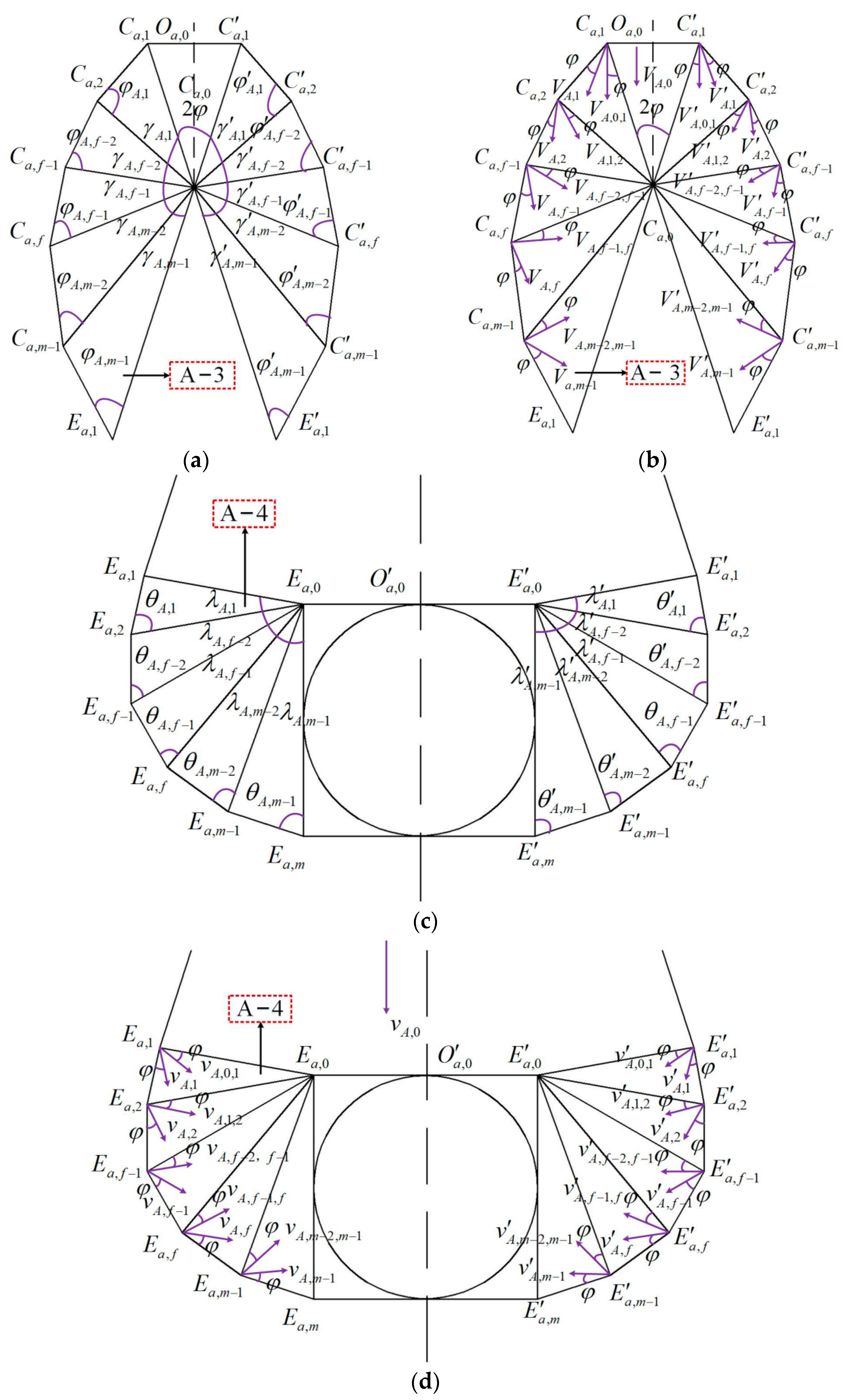
Figure 4.
Verification analysis: (a) the three-dimensional numerical simulation model; (b) the equivalent plastic strain diagram (i.e., PEEQ, ); (c) the strain curve diagram; (d) the factor of safety graph (SRM―the strength reduction method).
Figure 4.
Verification analysis: (a) the three-dimensional numerical simulation model; (b) the equivalent plastic strain diagram (i.e., PEEQ, ); (c) the strain curve diagram; (d) the factor of safety graph (SRM―the strength reduction method).

Figure 5.
The geological profile.

Figure 6.
The influence of the internal friction angle on the behavior of the tunnel: (a) the instability probability graph; (b) the reliability indicator graph.
Figure 6.
The influence of the internal friction angle on the behavior of the tunnel: (a) the instability probability graph; (b) the reliability indicator graph.

Figure 7.
The impact of the angle of internal friction on the behavior of the cavity: (a) the instability probability graph; (b) the reliability indicator graph.
Figure 7.
The impact of the angle of internal friction on the behavior of the cavity: (a) the instability probability graph; (b) the reliability indicator graph.

Figure 8.
The influence of the diameter of tunnel on the behavior of the tunnel: (a) the instability probability graph; (b) the reliability indicator graph.
Figure 8.
The influence of the diameter of tunnel on the behavior of the tunnel: (a) the instability probability graph; (b) the reliability indicator graph.

Figure 9.
The influence of the cavity diameter on the behavior of the cavern: (a) the instability probability graph; (b) the reliability indicator graph.
Figure 9.
The influence of the cavity diameter on the behavior of the cavern: (a) the instability probability graph; (b) the reliability indicator graph.

Table 1.
Explanation table for the signs.
| Symbol | Meaning | Symbol | Meaning |
|---|---|---|---|
| c | cohesion of geotechnical bodies | Poisson’s ratio | |
| internal friction of geotechnical body | strain of geotechnical mass | ||
| tunnel diameter | E | elastic modulus | |
| self–weight | buried depth of the tunnel | ||
| diameter of karst cave | safety factor of each failure area | ||
| buried depth of karst cave | COV | coefficient of variation of rock and soil parameters |
Table 2.
The table of engineering parameters for physical characteristic indicators of the rockmass.
Table 2.
The table of engineering parameters for physical characteristic indicators of the rockmass.
| Geotechnical Body Type | c | E | ||||||||
|---|---|---|---|---|---|---|---|---|---|---|
| Mean (kPa) | COV | Mean (°) | COV | Mean (kN/m3) | COV | Mean (MPa) | COV | Mean | COV | |
| Moderately weathered dolomite | 1000 | 0.189 | 45 | 0.197 | 27 | 0.055 | 53.8 | 0.155 | 0.3 | / |
c―cohesion of the rockmass, ―internal friction angle, ―the weight of the rock-soil mass, E―elastic modulus, ―Poisson’s ratio, COV―coefficient of variation.
Disclaimer/Publisher’s Note: The statements, opinions and data contained in all publications are solely those of the individual author(s) and contributor(s) and not of MDPI and/or the editor(s). MDPI and/or the editor(s) disclaim responsibility for any injury to people or property resulting from any ideas, methods, instructions or products referred to in the content. |
© 2024 by the authors. Licensee MDPI, Basel, Switzerland. This article is an open access article distributed under the terms and conditions of the Creative Commons Attribution (CC BY) license (https://creativecommons.org/licenses/by/4.0/).
Share and Cite
MDPI and ACS Style
Wu, B.; Sun, W.; Meng, G. A Calculation Method for Reliability Index of a Deep–Bedded Karst Tunnel Construction with Cavity Located Ahead of Tunnel Working Face. Buildings 2024, 14, 1349. https://doi.org/10.3390/buildings14051349
AMA Style
Wu B, Sun W, Meng G. A Calculation Method for Reliability Index of a Deep–Bedded Karst Tunnel Construction with Cavity Located Ahead of Tunnel Working Face. Buildings. 2024; 14(5):1349. https://doi.org/10.3390/buildings14051349
Chicago/Turabian StyleWu, Bo, Wentao Sun, and Guowang Meng. 2024. "A Calculation Method for Reliability Index of a Deep–Bedded Karst Tunnel Construction with Cavity Located Ahead of Tunnel Working Face" Buildings 14, no. 5: 1349. https://doi.org/10.3390/buildings14051349
Note that from the first issue of 2016, this journal uses article numbers instead of page numbers. See further details here.