
Experimental and Finite Element Analyses of Adjustable Foundation Bolts in Transmission Towers
1
Jiangxi Province Traffic Construction Engineering Quality Supervision Administration, 218 Gaoxin Third Road, Nanchang 330069, China
2
Department of Engineering Mechanics, Nanchang University, 999 Xuefu Avenue, Nanchang 330031, China
3
Jiangxi Gandong Road & Bridge Construction Group Ltd., 1288 Yingbin Avenue, Fuzhou 344000, China
4
Zhejiang Provincial Erjian Construction Group Ltd., 519 Minhe Road, Ningbo 315202, China
5
College of City Construction, Jiangxi Normal University, 99 Ziyang Avenue, Nanchang 330022, China
*
Authors to whom correspondence should be addressed.
Buildings 2024, 14(5), 1357; https://doi.org/10.3390/buildings14051357
Submission received: 30 March 2024
/
Revised: 22 April 2024
/
Accepted: 26 April 2024
/
Published: 10 May 2024
(This article belongs to the Special Issue Advance in Eco-Friendly Building Materials and Innovative Structures)
Abstract
:Uneven settlement of transmission tower foundations can result in catastrophic events, such as tower collapse and line failures, disrupting power transmission operations. To address the challenging repairs caused by uneven foundation settlement of transmission towers, we propose an adjustable foundation bolt (AFB). This paper provides a detailed theoretical analysis of the AFB’s stability and load-bearing capacity, including critical buckling force formulas and maximum normal stress expressions. Finite element simulations confirm the precision of our theoretical formulations. Additionally, we introduce a method using baffles to enhance its load-bearing capacity, analyzing the impact of different numbers of baffles through numerical simulations. The experimental results validate the effectiveness of baffles in enhancing structural load-bearing capacity. The device brings convenience and efficiency to the maintenance of transmission towers.
1. Introduction
In the field of power systems, transmission towers play a pivotal role [1,2,3,4]. The reliability of transmission tower structures directly determines the operational integrity of the entire transmission system, significantly impacting grid security [5,6,7,8]. Most transmission tower foundations are standalone concrete structures connected to the upper structure of the transmission tower via bolts [9,10,11]. In areas with complex geological conditions, such as mine subsidence areas, uneven settlement of foundations is common. As shown in Figure 1, this phenomenon may result in tower tilting, leading to severe accidents such as tower collapse and line failures [12,13,14,15,16]. Currently, the methods for dealing with uneven settlement of transmission tower foundations include the following: ① realignment is needed when the foundation experiences significant settlement, making it difficult to carry out repair work on the existing tower foundation, to bypass the settlement area and construct a new section of the transmission line [17,18]; ② live resetting of the foundation needed in cases where the tower body is balanced and has reliable support; the tower body is lifted and the foundation is raised using jacks, specialized shims are used to raise each foundation to the same height, and tower materials that have deformed significantly and are no longer functioning properly are replaced [19]; ③ Live correction of the tower body is needed when the tower foundation has experienced uneven settlement and it is predicted that further settlement will occur, shims can be added to the foundation and the tower body can be corrected. This method is flexible, fast in construction, requires minimal investment, and can be used as a temporary solution during the active settlement period of the foundation [20]; ④ Replacement of the tower with a combined foundation is needed when the uneven settlement of the tower foundation is complete and further settlement is unlikely to occur; a new tower with a combined foundation can be erected without changing the route of the transmission line. The combined foundation has strong resistance to uneven settlement, and when the foundation experiences uneven settlement, the tower and foundation only undergo rigid body displacement without causing structural damage to the tower. However, this method requires power outage during construction, has a long construction period, and involves significant investment [21]; ⑤ Live lifting and reinforcement of the original foundation can be employed after using the method of live resetting of the foundation; the split foundation at the same height is transformed and reinforced to a combined foundation to enhance its ability to resist uneven settlement of the foundation [22]. However, these methods have certain drawbacks, resulting in less-than-ideal outcomes after repairs. The identified issues can be summarized as follows: ① existing methods have limitations in adjustability, high costs, long construction periods, and low operability, leading to suboptimal technical and economic feasibility that fails to meet the demands of engineering practices; ② the uneven settlement of transmission tower foundations in subsidence areas varies, necessitating individual repair plans for each tower with a high degree of repetitive work and low efficiency; ③ transmission towers are subject to continuous behavior, while existing methods are essentially one-time corrections. In the event of subsequent uneven foundation settlement, device replacement and re-repair are required, leading to wastage.
This paper proposes the use of an AFB to effectively address the aforementioned issues. The present paper will first introduce the structure and characteristics of the AFB, followed by a detailed analysis of its stability and bearing capacity. Subsequently, finite element numerical simulations of the AFB before concrete infusion will be conducted to verify its alignment with theoretical values. This paper will also analyze the relationship between the installation of different numbers of baffles and the structural bearing capacity of the AFB. Finally, through the establishment of a 1:1 test model, experimental measurement results will be compared with theoretical analysis results to analyze the sources of result errors and confirm the operational mechanism of the AFB. Through these studies, we aim to comprehensively explore the performance and applications of an AFB, providing valuable references for research and practical applications in related fields.
2. Theoretical Analysis of AFB
2.1. Structural Composition and Characteristics of AFB
The AFB primarily consists of original tower base bolts, internal threaded connecting sleeves, elongated screws, base plates, and nuts. Its operational principle involves connecting the sleeve and elongated screw to the original base bolt, adjusting the position of the base plate on the elongated screw to alter the height of each tower leg. This action aims to realign all tower legs to the same horizontal height, counteracting the effects of foundation settlement, straightening the tower body, and eliminating the negative impacts of foundation settlement.
For transmission towers requiring emergency repairs, the first step is to determine the necessary height adjustment values for each tower leg. Subsequently, the corresponding adjustable base bolt scheme should be selected based on the required height adjustment values for construction. When carrying out repair work, the tower legs and base plate should be first raised to the desired height. Then, using pre-prepared sleeves, the original base bolts are connected to extended screws, and the base plate is connected to the extended screws using nuts. Finally, concrete is poured into the cavities of the extended screws and the base plate to complete the construction of the adjustable base bolt device. The structural composition and construction process of the AFB are depicted in Figure 2. In this figure, sections I, II, and III correspond to three states of a single tower leg during the repair process: pre-repair, representing the base without the adjusted leg height; during repair, showcasing the adjusted leg heights without the concrete filling; post-repair completion, illustrating the adjusted leg heights with the concrete filling to enhance the structural load-bearing capacity.
2.2. Stability of Single Foundation Bolt
For the AFB where concrete is not filled between the base plate and the foundation, the symmetrical nature of the structure ensures that each foundation bolt experiences the same loading and constraint conditions. Consequently, the stability of the entire structure is contingent upon the stability of each individual foundation bolt. When examining a single bolt, its stability can be analogized to that of a compression strut stability problem. The mechanical model of a single bolt with one end fixed and the other end free is depicted in Figure 3.
2.2.1. The Energy Method
Using the Rayleigh–Ritz method within the energy approach to solve for the critical buckling force [23,24], this method is based on the variational principle, which approximates the vibration modes or instability modes of a structure by selecting appropriate shape functions, and then uses the principle of minimizing the structural potential energy or energy function to determine the system’s eigenvalues and eigenvectors, thus obtaining the vibration frequencies or critical instability forces of the structure.
For a single bolt, when discussing its stability, the portion between its base plate and the concrete foundation can be simplified as a variable cross-section beam. This beam has n different moments of inertia, denoted as , ,..., , with an elastic modulus of E. Assuming the beam is fixed at the bottom and free at the top, we can hypothesize the deflection curve equation as
The bending moment at any section of the member is given by
The deformation energy added to the member due to bending is given by
where
Here, is the moment of inertia of the i-th beam, is the initial coordinate of the i-th beam, and is the endpoint coordinate of the i-th beam.
After the axis of the member changes from a straight line to a curve, the displacement at the upper end should be
Expanding into a series and neglecting higher-order terms, we obtain
By substituting (6) into (5), we have
In the above process of slight bending, the work performed by the pressure P should be
By substituting and into the condition to determine the critical pressure , we can solve for the critical pressure as follows:
2.2.2. Method of Minimum Cross-Section
In the method of minimum cross-section, the variable cross-section compression member is treated as a constant cross-section compression member, with the moment of inertia of the minimum cross-section of the variable cross-section member being used as its moment of inertia. The critical buckling force is determined by applying Euler’s formula for a slender compression member with a constant cross-section.
The critical force calculation expression obtained through the method of minimum cross-section is represented by Equation (10). A comparative analysis between the two methodologies reveals that while the energy method provides a satisfactory approximate solution, it involves a more intricate integration process. In contrast, the minimum cross-section method simplifies calculations by replacing all sections with the minimum cross-section, resulting in a more conservative estimation of the critical buckling load. In practical engineering applications, it is recommended to initially assess stability using the method of minimum cross-section and resort to the energy method for design if the stability criteria are not met.
2.3. The Stability of the Integral Structure of the AFB
When analyzing the overall structural stability of the AFB without a concrete filling between the tower base plate and the foundation, it can be approached as a strut stability problem. The overall stability of this structure can be calculated using the parallel axis theorem [25,26].
Here, A is the cross-sectional area of a single bolt, a is the spacing between the bolts, is the moment of inertia of a single bolt, and is the overall structure’s moment of inertia.
The results obtained under the ideal condition of short bolt lengths are applicable for theoretical analysis only. The expression for calculating the actual critical force in engineering applications should fall between Equations (10) and (12).
2.4. Structural Strength under Unfilled Concrete Conditions
A schematic diagram of the AFB between the tower base plate and the foundation without being filled with poured concrete is shown in Figure 4.
For the AFB, it is evident that under the combined action of horizontal and vertical forces, the critical section of the component is the section at the interface between the original foundation on the bolt and the top surface of the concrete foundation, where the maximum normal stress at this section is denoted as
For the AFB with four foundation bolts, where , , , and , we can substitute the load and foundation bolt dimensions into Equation (13). We then have
Here, , , and represent the forces acting on the tower base plate in the x-axis, y-axis, and z-axis directions, respectively; d is the diameter of the AFB; l is the total length of the bolt rod between the tower base plate and the foundation base.
3. Numerical Simulation of AFB
Using the general finite element software ANSYS for the numerical simulation of the AFB [27,28,29], full-scale modeling of the tower base plate and the extended part of the foundation bolts is conducted. The finite element foundation prototype is based on the relevant design from a certain provincial power design institute, selected for a certain transmission line project tower foundation. Through numerical simulation studies, comparing numerical solutions with theoretical solutions can validate the accuracy of the theoretical model and various calculation expressions, providing a basis for the design of the AFB.
3.1. Finite Element Validation of Structural Strength Issues under the Condition of No Concrete Filling
In the AFB without poured concrete, a single screw’s lower end is fixed in the concrete foundation, while the upper end is connected to the tower base plate. The dimensions of the AFB without poured concrete are shown in Figure 5, with the bolt length as . For ease of analysis, this bolt section is treated as a uniform cross-section with a diameter . The center-to-center distance between adjacent screws is , and the material’s elastic modulus is , adopting the 5 mm Solid186 solid element. The established finite element computational model is depicted in Figure 6. We constrain all degrees of freedom at the lower end of the base bolt, while the upper end of the base bolt is connected to the tower base plate using nodal coupling for equivalence [30,31].
At this point, a combined load is applied at the center of the tower base plate as follows:
where trending downwards is considered positive.
After computation, the following results are obtained (Figure 7).
Under the combined load, the maximum compressive stress is located at the lower end of the foundation bolt, with a maximum value of 291 MPa. By substituting the combined load (15) and the dimensions of the foundation bolt model into the expression for calculating the compressive stress under the condition of no concrete filling (14), the calculated value for is 278 MPa.
The obtained data are shown in Table 1.
Based on Table 1, it is evident that the maximum compressive stress value at the critical section of the bolt obtained from the finite element numerical calculations closely aligns with the theoretical solution. This indicates that the operational mechanism of the AFB under unfilled concrete conditions conforms to the theoretical analysis. By utilizing the expression for calculating the maximum compressive stress, we can accurately determine the maximum compressive stress at the critical section of the structure.
3.2. The Impact of Adding Baffles on Structural Strength
When using a sleeve to connect the original foundation bolt with an extended rod to adjust the height of the tower base plate, it is necessary to pour concrete between the tower base plate and the foundation to enhance the structural load-bearing capacity. However, before the poured concrete reaches the design strength and becomes effective, the structural load-bearing capacity is weaker and prone to damage. In such cases, support devices or other methods are needed to enhance the structural load-bearing capacity. Using a barrier between the tower base plate and the foundation is a simple, convenient, economical, and effective method. The improved AFB with baffles is shown in Figure 8.
The Influence of the Number of Baffles on the Maximum Compressive Stress
The addition of baffles affects the degree of deformation characteristics and stress conditions of the bolts, which are related to the number of baffles, barrier spacing, and barrier thickness. Taking a 10 mm thick barrier as an example, the impact of the number of baffles on the maximum compressive stress at the critical section of the foundation bolts is discussed.
- (1)
- Without using baffles
Establishing a finite element model of an AFB without adding baffles: The dimensions of the tower base plate are , with an elastic modulus of . The length of the foundation bolts between the tower base plate and the foundation is , with a diameter of , and a center distance between adjacent bolts of , adopting the 5 mm Solid186 solid element. In the finite element model, the foundation part is not established, and the effect of the foundation part on the foundation bolts is simplified to a fixed-end constraint at the lower end of the foundation bolts.
We apply the following load combination at the center of the surface of the tower base plate:
The finite element calculation results in a maximum compressive stress of 394 MPa. Substituting the load combination (16) into (14), we obtain
The results are very close, once again demonstrating the accuracy of the expression for calculating the maximum compressive stress at the critical section of the AFB in the absence of poured concrete and baffles.
- (2)
- Using one baffle
On the basis of the finite element model without baffles, we add one baffle with dimensions and an elastic modulus . The distance from the bottom surface of the baffle to the bottom surface of the tower base plate is 300 mm, adopting the 5 mm Solid186 solid element. The finite element calculation model and the stress distribution obtained from the calculation are shown in Figure 11.
After adding one baffle, the maximum normal stress at the critical section is −261 MPa. Relative to the maximum normal stress without a baffle, denoted as −394 MPa, the maximum normal stress at the critical section after adding one baffle is decreased by 33.7%.
The results obtained with different numbers of baffles are listed in Table 2.
4. Experimental Measurement and Analysis of AFB
4.1. Experimental Objectives
This experiment utilized the base section of a transmission tower designed by a specific power engineering institute as the prototype model. A simulation was conducted using a design scheme for the AFB with a maximum adjustability of 500 mm, and a 1:1 scale experimental model was created.
The objectives of the experiment are as follows:
- (1)
- To determine the strain and stress distribution at the critical section of the AFB, compare the theoretical analysis results with the experimental results, and validate the theoretical model.
- (2)
- To validate the effectiveness of the AFB and investigate the impact of adding baffles on the load-bearing capacity of the device.
- (3)
- By analyzing the experimental data, to provide a basis for proposing the applicable conditions, design methods, and construction considerations for the AFB.
4.2. Experimental Setup and Data Collection
The structure and configuration of the AFB test device are illustrated in Figure 13.
For transmission towers, the forces from the upper structure are transmitted through the tower legs to the tower base plate and further into the foundation. In the experiment, the pressure from a jack is used to simulate the forces from the upper structure on the foundation. These forces can be simplified into two types of directional loads: vertical loads and horizontal loads. Both of these loads pass through the center of the tower base plate, and the magnitude of the loads is measured by pressure sensors located beneath the cross-beam, as shown in Figure 14.
When conducting the experiment, each foundation bolt is first labeled, and four strain gauges are mounted on each foundation bolt, as shown in Figure 15.
4.3. Analysis of Experimental Results
4.3.1. AFB without Baffle
The setup for condition 1 is an AFB without the addition of baffles, as depicted in Figure 16.
Applying loads and along the x and z axes, respectively, the strain values of each strain gauge measured after distributing the loading are listed in Table 3.
We calculate the axial strain of each bolt using the average strain values of strain gauges 1 to 4, as listed in Table 3. We then determine the axial force and record the results in Table 4.
From an analysis of Table 4, it is evident that initially, due to factors like the non-compacted gaps in the setup, the axial forces calculated from the strain back-calculation, denoted as , differ significantly from the applied external load . Additionally, the distribution of axial forces among the bolts is also uneven. However, as the load increases, gradually approaches , and the axial forces in each bolt tend to become more uniform.
4.3.2. AFB with Baffles
The setup for condition 2 is an AFB with two added baffles, as shown in Figure 17.
Applying loads and along the x and z axes, respectively, the strain values of each strain gauge measured after distributing the loading are listed in Table 5.
We calculate the axial strain of each bolt using the average strain values of strain gauges 1 to 4, as listed in Table 5. We then determine the axial force and record the results in Table 6.
An analysis of Table 6 shows that for the AFB with added baffles, at the beginning of loading, due to reasons such as the device gaps not being compacted, the axial forces calculated through strain back-calculations differ significantly from the applied load . The proportion of axial forces between the bolts also shows weak regularity, with bolt B not even sharing any axial force. As the load increases, gradually approaches , and each bolt begins to proportionally share the vertical load.
It is also observed that there is a significant difference in axial forces between bolts A and B compared to bolts C and D. This is because under the action of the baffles, the upper extended bolts undergo partial deformation coordination. Under horizontal forces, bolts A and B are under tension on one side, while bolts C and D are under compression on the other side. Furthermore, a comparison of the results between condition 1 and condition 2 is conducted. From Table 4 and Table 6, the strain values of all strain gauges on each bolt corresponding to the 10th load step are extracted and listed in Table 7.
It is important to note that the loads applied in the 10th load step for condition 1 and condition 2 are different, so a qualitative discussion is conducted here. Under the same vertical compression force , condition 1 applies a horizontal force , while condition 2 applies a horizontal force . Therefore, the horizontal load in condition 2 is greater than that in condition 1. Despite this, the maximum microstrain in each strain gauge in condition 2 is still less than the maximum microstrain in each strain gauge in condition 1. This indicates that adding baffles can significantly reduce the stress values on the critical sections of the foundation bolts, thereby enhancing the load-bearing capacity of the components. Therefore, it is recommended to install baffles during emergency repairs to improve the stress distribution at the critical sections of the bolts.
5. Conclusions
This study delved into the structural composition and operational principles of the AFB, employing a combination of theoretical analysis, numerical simulation, and experimental measurements, leading to the following conclusions:
- (1)
- The AFB primarily comprises components such as the original foundation bolt, internal threaded connecting sleeve, extension screw, tower base plate, and nut. Compared to conventional methods, the utilization of this equipment offers advantages including structural simplicity, low construction complexity, high versatility, and expedited repairs.
- (2)
- Concerning the stability of the AFB, expressions for the critical buckling force of individual foundation bolts were derived using energy and minimum section methods. Addressing its strength concerns, an expression for the maximum normal stress at the critical section of the AFB before concrete filling was provided.
- (3)
- Finite element numerical simulations were conducted for the AFB, revealing a mere 4.46% deviation between the finite element value and the theoretical value of the maximum normal stress at the foundation bolt’s critical section, validating the accuracy of the expression for maximum stress at the critical section of the foundation bolt. Additionally, by incorporating varying numbers of baffles into the finite element model, it was observed that the addition of baffles effectively reduces stress at the critical section, significantly enhancing the structural load-bearing capacity.
- (4)
- By establishing a 1:1 experimental model, stress and strain distribution characteristics of different configurations of the AFB under combined loads were obtained. A comparative analysis of the experimental measurements with theoretical predictions identified sources of error, revealing slight deviations attributed to bolt positioning discrepancies and clearances between the sleeve and screw, potentially hindering the proportional distribution of loads among the bolts through the tower base plate. However, the introduction of baffles not only substantially enhances the structural load-bearing capacity but also mitigates the impact of these factors on force transmission.
Recommendations and Future Perspectives:
Currently, there are various methods to address the issue of uneven settlement in the foundations of transmission line towers, but the results have not been entirely satisfactory. While this paper proposes an adjustable foundation bolt as a solution and has achieved some success, there are still some shortcomings in the research process. Areas that require further investigation include the following: ① The need to expand the applicability conditions of the adjustable foundation bolt device to allow for more diverse distribution forms of foundation bolts on a single support and to make the device usable in a wider range of scenarios. ② The need for further research on methods to enhance the structural load-bearing capacity. ③ The need to take appropriate measures to mitigate or avoid stress concentration problems, ensuring the safety and reliability of the structure.
Author Contributions
Conceptualization, M.H., H.Y. and Z.H.; methodology, M.H. and H.Y.; software, X.X., Z.H. and T.Z.; validation, H.Y. and T.Z.; formal analysis, X.X., T.Z. and Z.H.; writing—original draft preparation, X.X. and M.H. All authors have read and agreed to the published version of the manuscript.
Funding
This research was supported by the Jiangxi Provincial Natural Science Foundation (Awards Nos. 20224BAB214072), the Ningbo Municipal Housing and Urban-Rural Development Bureau Science and Technology Project (Awards Nos. NB2023044), and the Jiangxi Province Education Science “14th Five-Year Plan” Project (Awards Nos. 22QN007).
Data Availability Statement
The data in this study are available from the corresponding author upon request.
Conflicts of Interest
Authors Zhi Huang and Tengfei Zhao were employed by Jiangxi Gandong Road & Bridge Construction Group Ltd., and Zhejiang Provincial Erjian Construction Group Ltd, respectively. The remaining authors declare that the research was conducted in the absence of any commercial or financial relationships that could be construed as a potential conflict of interest.
References
- Chen, M.L. Exploration of Structural Design Optimization for Overhead Transmission Line Towers. Ind. Des. 2017, 8, 167–168. [Google Scholar]
- Chen, W.D.; Li, J.C.; Yu, Y.C.; Sun, G.; Xia, K.Q. Reliability Calculation of Transmission Tower Structural System under Multiple Working Conditions. Eng. Mech. 2013, 30, 180–183. [Google Scholar]
- Meng, X.Q.; Wang, J.F.; Cheng, A.L.; Zheng, Y.X.; Zhang, S.L. Design and Computational Analysis of Long-Span Transmission Tower Structures. Eng. Constr. 2023, 37, 507–511+553. [Google Scholar]
- Hu, X.Y.; Ren, X.F.; Chen, J. Analysis of Reinforcement Methods for Transmission Tower Structures. Energy Environ. 2022, 5, 29–31. [Google Scholar]
- Zhang, W.N.; Wang, Y.; Zhang, L.B.; Wu, K.H.; Wang, X.C. Progress and Prospects of Health Monitoring Technology for Bolted Connections in Transmission Towers. China Electr. Power 2021, 54, 18–26. [Google Scholar]
- Wang, J. Optimization of Vibration Monitoring Sensor Placement for Transmission Towers and Analysis of Structural Condition Parameters; North China Electric Power University: Beijing, China, 2017. [Google Scholar]
- Sun, D. Research on the Mechanical Calculation Model of Power Transmission Line Towers in Mining Areas and the Interaction Mechanism of Tower-Line System; China University of Mining and Technology: Xuzhou, China, 2010. [Google Scholar]
- Jiang, T. Overhead Transmission Line Tower Structure Design. China High-Tech 2023, 22, 24–26. [Google Scholar]
- Cao, X.Y.; Feng, D.C.; Wang, Z.; Wu, G. Parametric investigation of the assembled bolt-connected buckling-restrained brace and performance evaluation of its application into structural retrofit. J. Build. Eng. 2022, 48, 103988. [Google Scholar] [CrossRef]
- Cao, X.Y.; Feng, D.C.; Wang, G. Seismic performance upgrade of RC frame buildings using precast bolt-connected steel-plate reinforced concrete frame-braces. Eng. Struct. 2019, 195, 382–399. [Google Scholar] [CrossRef]
- Cao, X.J. Experimental and numerical study of outside strengthening with precast bolt-connected steel plate–reinforced concrete frame-brace. J. Perform. Constr. Facil. 2019, 33, 04019077. [Google Scholar] [CrossRef]
- Yang, G.; Wang, T.Z.; Wang, D.W. Influence of Deformation Process of Tower Foundation in Goaf on Safety of Transmission Tower. Sci. Technol. Eng. 2019, 19, 206–212. [Google Scholar]
- Li, H.H.; Wang, Z.Q.; Li, H.Y.; Liang, W.; An, L.Q. Design and Experimental Study of Height-Adjustable Tower Structure Adapted to Uniform Foundation Settlement. Power Syst. Technol. 2007, 31, 83–86. [Google Scholar]
- Yang, F.L. Analysis of Dynamic Impact Effect on Transmission Tower Structure during Deformation Process of Goaf Foundation. Vib. Impact 2018, 37, 181–186+195. [Google Scholar]
- Dai, Y.; Jiang, T.R.; Zhang, Y.H.; Zhang, Y.L.; Yu, B.; Wang, Y.Q. Construction and Application of Safety Evaluation Model for Transmission Towers under Uneven Settlement Conditions. Constr. Technol. 2017, 46, 1468–1471. [Google Scholar]
- Zhang, J.Q. Research on Safety Evaluation and Prevention Techniques of Overhead Transmission Lines in Goaf Area; North China Electric Power University: Beijing, China, 2008. [Google Scholar]
- Niu, C.J. Research on Reliability Evaluation Method of High Voltage Overhead Transmission Lines; North China Electric Power University: Beijing, China, 2008. [Google Scholar]
- Wang, X.G.; Qiao, L.; Sun, X.S. Numerical Simulation of Stability of Transmission Tower Foundation on Underground Goaf. Met. Mine 2008, 3, 110–113+143. [Google Scholar]
- Liu, Y.C.; Liu, Z.D. Key Technologies for In-situ Reinforcement and Correction of Inclined Transmission Tower. Rock Soil Mech. 2008, 1, 173–176. [Google Scholar]
- Qin, Q.Z.; Cao, Y.J.; Mao, T.Y.; Gong, Q. Research on Foundation Design of Ultra High Voltage Transmission Line in Coal Mining Influence Area. Electr. Power Constr. 2009, 30, 18–21. [Google Scholar]
- Wang, Y. Measures for Handling Replacement of Foundation Anchor Bolts in Transmission Lines. In Proceedings of the Annual Conference of the Jiangxi Electrical Engineering Society 2019, Nanchang, China, 12–15 November 2019; Jiangxi Electric Power Design Institute: Nanchang, China; Volume 2, p. 019969. [Google Scholar]
- Zhang, H.L. Analysis and Application Research on the Influence of Tunnel Construction on Overhead High-Voltage Transmission Towers; Central South University: Changsha, China, 2012. [Google Scholar]
- Magrab, E.B. Vibrations of Elastic Systems. Solid Mech. Its Appl. 2012, 184, 1–505. [Google Scholar]
- Xie, Y.B. Research on Basic Theory of Buckling of Variable Cross-section Long Compression Members; Chongqing University: Chongqing, China, 2009. [Google Scholar]
- Sun, X.F.; Fang, X.S.; Guan, L.T. Mechanics of Materials (I), 5th ed.; Higher Education Press: Beijing, China, 2009; pp. 305–321. [Google Scholar]
- Liu, H.W.; Lin, J.X.; Cao, M.L. Mechanics of Materials (I), 6th ed.; Higher Education Press: Beijing, China, 2017; pp. 304–323. [Google Scholar]
- Li, W.H.; Ye, Y.M. Practical Applications of ANSYS in Civil Engineering; China Water & Power Press: Beijing, China, 2007; pp. 303–343. [Google Scholar]
- Chavda, J.T.; Dodagoudar, G.R. Finite element evaluation of ultimate capacity of strip footing: Assessment using various constitutive models and sensitivity analysis. Innov. Infrastruct. Solut. 2018, 3, 1–10. [Google Scholar] [CrossRef]
- Deb, P.; Pal, S.K. Structural analysis of piled raft foundation in soft soil: An experimental simulation and parametric study with numerical method. Ocean Eng. 2022, 261, 112139. [Google Scholar] [CrossRef]
- Li, B.; Zhang, D.Q.; Zhang, G.C. Coupled Finite Element Analysis of Displacement and Tower-Line of 220 kV Transmission Tower Foundation in Goaf Area. In Proceedings of the 9th Annual Conference on Power Station Materials, Chengdu, China, 21–24 September 2011. [Google Scholar]
- Wang, X.M. Numerical Analysis of Engineering Structures with ANSYS; People’s Communications Press: Beijing, China, 2007; pp. 1–407. [Google Scholar]
Figure 1.
Transmission tower damaged by foundation settlement.
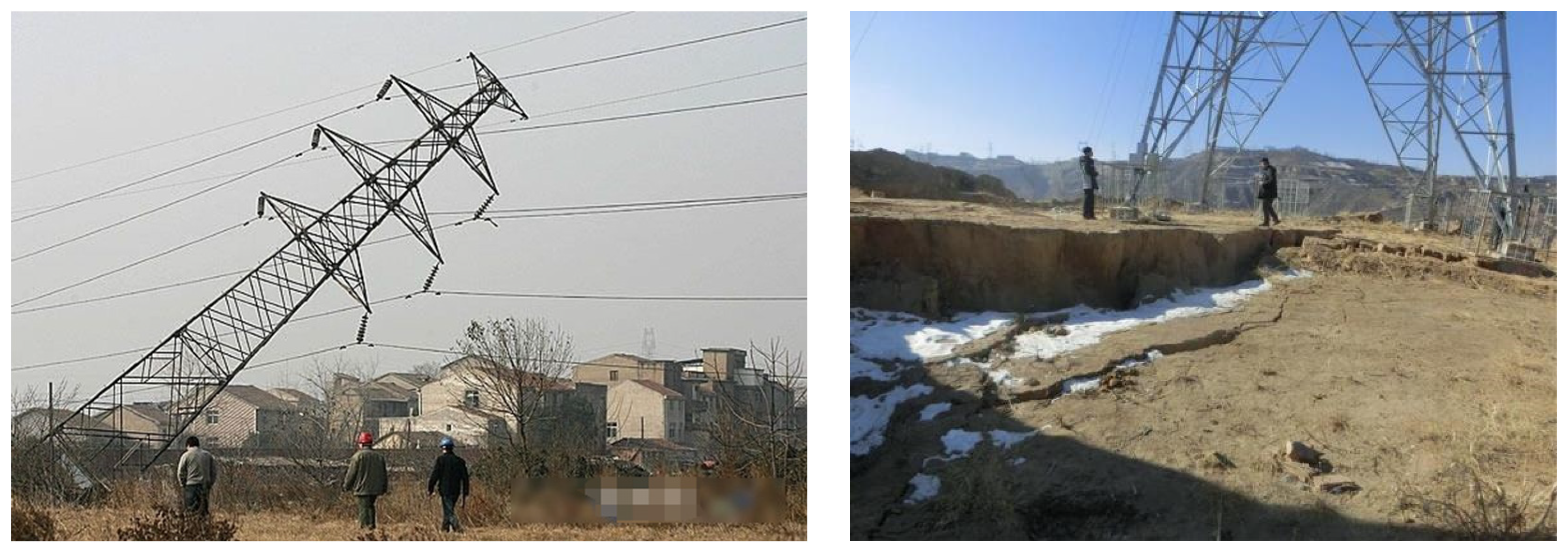
Figure 2.
Structure composition of AFB.

Figure 3.
Mechanical model of single bolt.

Figure 4.
AFB under unfilled concrete conditions.

Figure 5.
A size diagram of the foundation bolt and the tower base plate.

Figure 6.
Finite element model of AFB.
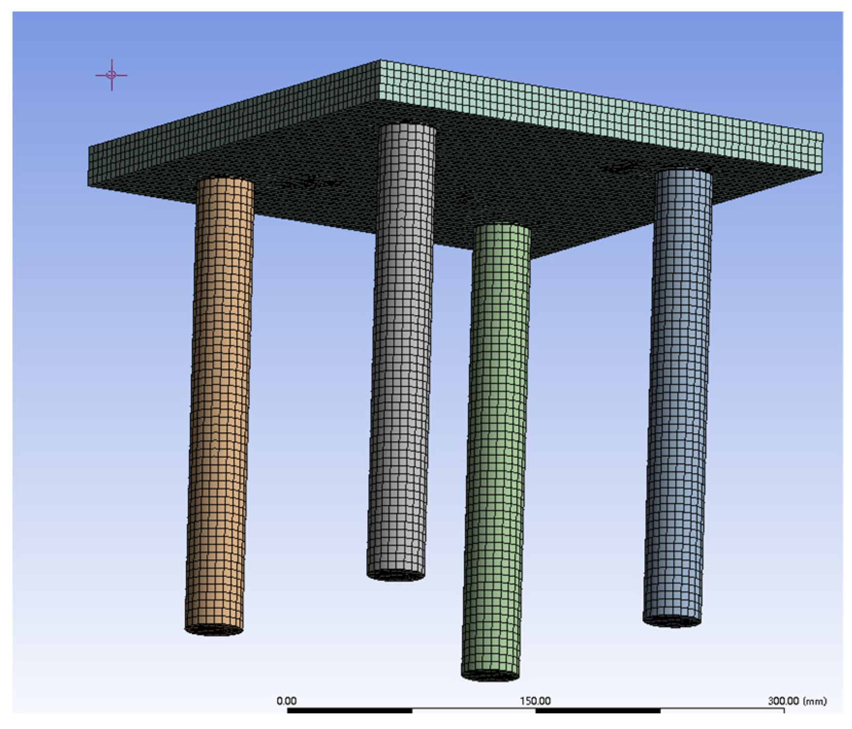
Figure 7.
A stress contour plot of the screw under the combined load.

Figure 8.
A diagram of the AFB improved with baffles.

Figure 9.
Finite element calculation model without baffles.

Figure 10.
Stress distribution of bolts without baffles.

Figure 11.
Finite element calculation model and stress distribution when using one baffle.

Figure 12.
Maximum tensile stress situation of screws in dangerous section when using different numbers of partitions.
Figure 12.
Maximum tensile stress situation of screws in dangerous section when using different numbers of partitions.
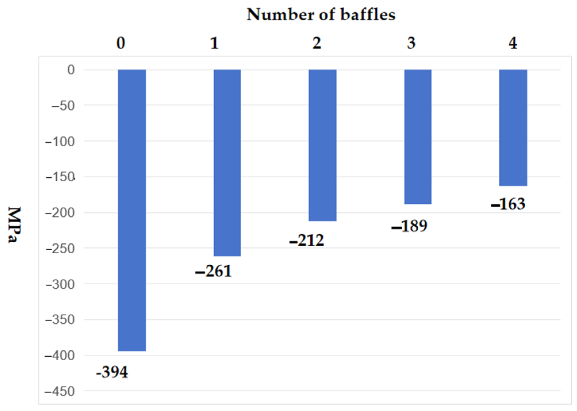
Figure 13.
Front view of AFB test device.

Figure 14.
Diagram of load application.

Figure 15.
Arrangement diagram of strain gauges.
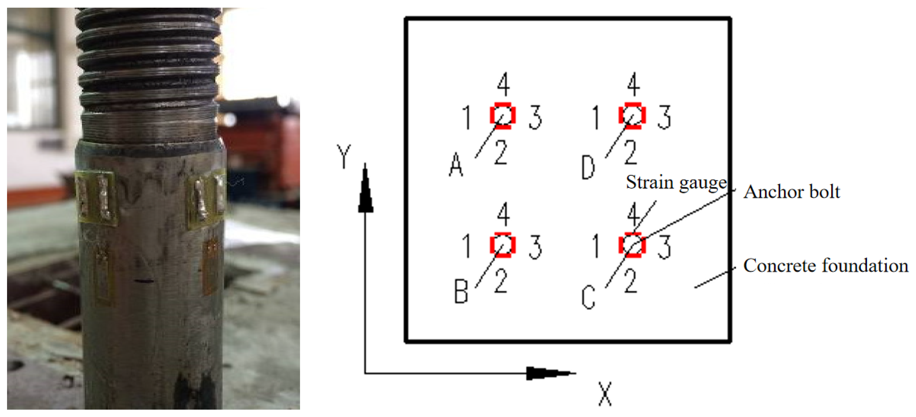
Figure 16.
A loading diagram of the setup for condition 1.

Figure 17.
A loading diagram of the setup for condition 2.


Table 1.
The maximum compressive stress at the critical section of the AFB.
| Theoretical Value () | Finite Element Value () | ||
|---|---|---|---|
| Maximum compressive stress | 278 MPa | 291 MPa | 4.46% |
Table 2.
A comparison of the maximum normal stress at the critical section with different numbers of baffles.
Table 2.
A comparison of the maximum normal stress at the critical section with different numbers of baffles.
| Number of Baffles | Maximum Normal Stress (MPa) | Reduce (%) |
|---|---|---|
| 0 | −394 | - |
| 1 | −261 | 33.7% |
| 2 | −212 | 46.2% |
| 3 | −189 | 52.0% |
| 4 | −163 | 58.6% |
Table 3.
The strain values of each strain gauge in condition 1.
| Load Steps | (kN) | (kN) | Strain Gauge | |||||||
|---|---|---|---|---|---|---|---|---|---|---|
| A () | B () | |||||||||
| 1 | 2 | 3 | 4 | 1 | 2 | 3 | 4 | |||
| 1 | 3.40 | 0.31 | 45.54 | −4.54 | −84.12 | −7.22 | 30.52 | −19.15 | −63.55 | −18.42 |
| 2 | 7.11 | 0.58 | 82.59 | −13.83 | −130.80 | −19.25 | 67.41 | −30.99 | −107.73 | −26.31 |
| 3 | 10.67 | 0.91 | 114.40 | −30.59 | −173.31 | −28.81 | 103.55 | −42.45 | −151.71 | −35.19 |
| 4 | 14.15 | 1.18 | 144.90 | −34.44 | −200.29 | −30.28 | 134.17 | −56.21 | −192.88 | −49.48 |
| 5 | 18.11 | 1.49 | 168.02 | −40.91 | −253.52 | −38.66 | 167.77 | −67.27 | −250.77 | −58.12 |
| 6 | 21.62 | 1.80 | 191.13 | −53.48 | −303.85 | −46.07 | 204.08 | −79.86 | −303.73 | −67.12 |
| 7 | 25.35 | 2.09 | 219.84 | −63.38 | −352.96 | −54.32 | 233.05 | −90.58 | −365.25 | −75.98 |
| 8 | 28.70 | 2.38 | 253.69 | −73.26 | −395.90 | −60.08 | 272.52 | −101.56 | −428.54 | −83.04 |
| 9 | 32.32 | 2.68 | 295.08 | −88.28 | −447.51 | −69.40 | 320.66 | −110.16 | −503.32 | −91.17 |
| 10 | 35.58 | 2.98 | 339.18 | −97.74 | −509.68 | −84.26 | 372.29 | −112.61 | −568.06 | −92.98 |
| Load Steps | (kN) | (kN) | Strain Gauge | |||||||
| C () | D () | |||||||||
| 1 | 2 | 3 | 4 | 1 | 2 | 3 | 4 | |||
| 1 | 3.40 | 0.31 | 25.86 | −14.01 | −66.50 | −18.13 | 20.45 | −6.34 | −57.59 | −1.46 |
| 2 | 7.11 | 0.58 | 61.07 | −19.69 | −128.76 | −21.72 | 60.25 | −14.81 | −102.37 | −8.70 |
| 3 | 10.67 | 0.91 | 85.51 | −30.67 | −190.08 | −29.71 | 98.11 | −27.63 | −146.01 | −22.10 |
| 4 | 14.15 | 1.18 | 118.09 | −46.49 | −248.87 | −44.40 | 130.07 | −39.61 | −183.58 | −31.48 |
| 5 | 18.11 | 1.49 | 156.93 | −62.97 | −302.69 | −62.81 | 202.78 | −57.02 | −277.49 | −30.49 |
| 6 | 21.62 | 1.80 | 198.84 | −65.32 | −358.94 | −72.54 | 237.30 | −68.46 | −341.89 | −44.56 |
| 7 | 25.35 | 2.09 | 246.80 | −74.80 | −403.99 | −81.68 | 248.49 | −74.64 | −371.78 | −52.28 |
| 8 | 28.70 | 2.38 | 275.23 | −81.07 | −451.28 | −89.80 | 284.80 | −85.56 | −433.64 | −56.95 |
| 9 | 32.32 | 2.68 | 312.09 | −95.97 | −504.21 | −99.68 | 301.32 | −88.33 | −461.70 | −67.34 |
| 10 | 35.58 | 2.98 | 362.49 | −107.63 | −556.13 | −111.09 | 345.31 | −97.86 | −527.29 | −75.91 |
Table 4.
Axial forces in each bolt in condition 1.
| Load Steps | (kN) | (kN) | (kN) | (kN) | (kN) | (kN) | |
|---|---|---|---|---|---|---|---|
| 1 | 3.40 | −1.17 | −1.64 | −1.69 | −1.05 | −5.56 | 163.31% |
| 2 | 7.11 | −1.89 | −2.27 | −2.54 | −1.53 | −8.24 | 115.79% |
| 3 | 10.67 | −2.76 | −2.93 | −3.84 | −2.27 | −11.80 | 110.62% |
| 4 | 14.15 | −2.80 | −3.83 | −5.16 | −2.90 | −14.69 | 103.79% |
| 5 | 18.11 | −3.84 | −4.85 | −6.32 | −3.78 | −18.80 | 103.81% |
| 6 | 21.62 | −4.94 | −5.74 | −6.94 | −5.07 | −22.69 | 104.95% |
| 7 | 25.35 | −5.84 | −6.96 | −7.30 | −5.83 | −25.93 | 102.27% |
| 8 | 28.70 | −6.42 | −7.93 | −8.08 | −6.78 | −29.21 | 101.78% |
| 9 | 32.32 | −7.22 | −8.94 | −9.03 | −7.36 | −32.55 | 100.73% |
| 10 | 35.58 | −8.21 | −9.35 | −9.60 | −8.28 | −35.44 | 99.62% |
Table 5.
The strain values of each strain gauge in condition 2.
| Load Steps | (kN) | (kN) | Strain Gauge | |||||||
|---|---|---|---|---|---|---|---|---|---|---|
| A () | B () | |||||||||
| 1 | 2 | 3 | 4 | 1 | 2 | 3 | 4 | |||
| 1 | 3.03 | 0.46 | 30.96 | −1.12 | −51.61 | −1.00 | 44.99 | −1.60 | −45.28 | −1.04 |
| 2 | 7.44 | 0.78 | 57.00 | −6.89 | −87.00 | −6.75 | 67.98 | −12.40 | −81.09 | −7.31 |
| 3 | 10.25 | 1.27 | 85.14 | −14.56 | −121.88 | −13.69 | 92.55 | −19.25 | −115.44 | −14.73 |
| 4 | 14.28 | 1.63 | 100.68 | −23.50 | −146.60 | −23.41 | 106.79 | −28.55 | −146.38 | −25.90 |
| 5 | 17.63 | 2.11 | 122.95 | −29.72 | −176.00 | −27.56 | 135.96 | −39.11 | −185.63 | −34.03 |
| 6 | 21.85 | 2.47 | 141.10 | −36.39 | −194.51 | −33.66 | 158.93 | −45.42 | −223.43 | −43.86 |
| 7 | 25.80 | 2.89 | 163.81 | −42.09 | −221.74 | −39.94 | 181.25 | −54.83 | −264.52 | −51.46 |
| 8 | 29.15 | 3.30 | 187.87 | −49.75 | −261.22 | −45.60 | 203.17 | −63.43 | −302.31 | −56.97 |
| 9 | 32.21 | 3.75 | 209.78 | −53.68 | −328.02 | −51.25 | 219.11 | −70.66 | −339.69 | −63.67 |
| 10 | 35.66 | 4.16 | 231.76 | −59.34 | −366.06 | −56.99 | 252.53 | −76.02 | −390.46 | −69.97 |
| Load Steps | (kN) | (kN) | Strain Gauge | |||||||
| C () | D () | |||||||||
| 1 | 2 | 3 | 4 | 1 | 2 | 3 | 4 | |||
| 1 | 3.03 | 0.46 | 22.62 | −6.09 | −66.01 | −14.42 | 16.20 | −11.89 | −60.09 | −18.30 |
| 2 | 7.44 | 0.78 | 44.23 | −22.65 | −118.43 | −27.00 | 33.01 | −23.79 | −102.18 | −29.19 |
| 3 | 10.25 | 1.27 | 69.93 | −32.86 | −168.32 | −43.30 | 51.23 | −31.14 | −148.05 | −39.77 |
| 4 | 14.28 | 1.63 | 87.87 | −45.12 | −213.75 | −57.48 | 73.88 | −40.93 | −190.51 | −48.38 |
| 5 | 17.63 | 2.11 | 107.19 | −57.94 | −266.63 | −67.96 | 95.57 | −50.76 | −247.69 | −58.02 |
| 6 | 21.85 | 2.47 | 124.13 | −68.87 | −315.06 | −83.67 | 118.28 | −63.82 | −295.45 | −71.61 |
| 7 | 25.80 | 2.89 | 146.33 | −83.22 | −362.52 | −95.84 | 143.27 | −73.65 | −345.65 | −88.65 |
| 8 | 29.15 | 3.30 | 172.32 | −96.75 | −405.90 | −105.20 | 169.16 | −86.15 | −391.01 | −101.32 |
| 9 | 32.21 | 3.75 | 197.43 | −105.37 | −442.95 | −113.18 | 200.47 | −105.59 | −446.13 | −115.76 |
| 10 | 35.66 | 4.16 | 240.32 | −117.52 | −491.50 | −122.52 | 228.50 | −116.61 | −481.12 | −131.59 |
Table 6.
Axial forces in each bolt in condition 2.
| Load Steps | (kN) | (kN) | (kN) | (kN) | (kN) | (kN) | |
|---|---|---|---|---|---|---|---|
| 1 | 3.40 | −0.53 | −0.07 | −1.49 | −1.72 | −3.81 | 125.87% |
| 2 | 7.11 | −1.02 | −0.76 | −2.88 | −2.84 | −7.51 | 100.97% |
| 3 | 10.67 | −1.51 | −1.32 | −4.06 | −3.91 | −10.81 | 105.43% |
| 4 | 14.15 | −2.16 | −2.19 | −5.32 | −4.80 | −14.47 | 101.35% |
| 5 | 18.11 | −2.57 | −2.86 | −6.64 | −6.08 | −18.15 | 102.96% |
| 6 | 21.62 | −2.88 | −3.58 | −8.00 | −7.28 | −21.73 | 99.46% |
| 7 | 25.35 | −3.26 | −4.41 | −9.20 | −8.49 | −25.37 | 98.34% |
| 8 | 28.70 | −3.93 | −5.11 | −10.14 | −9.53 | −28.71 | 98.50% |
| 9 | 32.32 | −5.20 | −5.94 | −10.81 | −10.87 | −32.81 | 101.87% |
| 10 | 35.58 | −5.84 | −6.61 | −11.44 | −11.66 | −35.55 | 99.69% |
Table 7.
Comparison of strain values for each strain gauge in condition 1 and condition 2.
| Experimental Number | (kN) | (kN) | Strain Gauge | |||||||
|---|---|---|---|---|---|---|---|---|---|---|
| A () | B () | |||||||||
| 1 | 2 | 3 | 4 | 1 | 2 | 3 | 4 | |||
| Condition 1 | 35.58 | 2.98 | 339.18 | −97.74 | −509.68 | −84.26 | 372.29 | −112.61 | −568.06 | −92.98 |
| Condition 2 | 35.66 | 4.16 | 231.76 | −59.34 | −366.06 | −56.99 | 252.53 | −76.02 | −390.46 | −69.97 |
| Load Steps | (kN) | (kN) | Strain Gauge | |||||||
| C () | D () | |||||||||
| 1 | 2 | 3 | 4 | 1 | 2 | 3 | 4 | |||
| Condition 1 | 35.58 | 2.98 | 362.49 | −107.63 | −556.13 | −111.09 | 345.31 | −97.86 | −527.29 | −75.91 |
| Condition 2 | 35.66 | 4.16 | 240.32 | −117.52 | −491.50 | −122.52 | 228.50 | −116.61 | −481.12 | −131.59 |
Disclaimer/Publisher’s Note: The statements, opinions and data contained in all publications are solely those of the individual author(s) and contributor(s) and not of MDPI and/or the editor(s). MDPI and/or the editor(s) disclaim responsibility for any injury to people or property resulting from any ideas, methods, instructions or products referred to in the content. |
© 2024 by the authors. Licensee MDPI, Basel, Switzerland. This article is an open access article distributed under the terms and conditions of the Creative Commons Attribution (CC BY) license (https://creativecommons.org/licenses/by/4.0/).
Share and Cite
MDPI and ACS Style
Yin, H.; Xiao, X.; Huang, Z.; Zhao, T.; Huang, M. Experimental and Finite Element Analyses of Adjustable Foundation Bolts in Transmission Towers. Buildings 2024, 14, 1357. https://doi.org/10.3390/buildings14051357
AMA Style
Yin H, Xiao X, Huang Z, Zhao T, Huang M. Experimental and Finite Element Analyses of Adjustable Foundation Bolts in Transmission Towers. Buildings. 2024; 14(5):1357. https://doi.org/10.3390/buildings14051357
Chicago/Turabian StyleYin, Huajie, Xianzhi Xiao, Zhi Huang, Tengfei Zhao, and Mojia Huang. 2024. "Experimental and Finite Element Analyses of Adjustable Foundation Bolts in Transmission Towers" Buildings 14, no. 5: 1357. https://doi.org/10.3390/buildings14051357
Note that from the first issue of 2016, this journal uses article numbers instead of page numbers. See further details here.