
Implementation and Verification of a Micro-Jet-Vane System of a Solid Rocket Motor for a Micro-Nano Satellite
Science and Technology on Combustion, Internal Flow and Thermo-Structure Laboratory, Northwestern Polytechnical University, Xi’an 710072, China
*
Author to whom correspondence should be addressed.
Aerospace 2024, 11(5), 384; https://doi.org/10.3390/aerospace11050384
Submission received: 27 February 2024
/
Revised: 25 April 2024
/
Accepted: 8 May 2024
/
Published: 10 May 2024
Abstract
:To achieve rapid vector maneuvering of a space micro-nano satellite, a micro-sized solid rocket motor was utilized as its propulsion system, and a micro-jet-vane-thrust-vector control system was devised. Computational fluid dynamics (CFD) numerical simulations were conducted on the designed micro-vane structure at various deflection angles to ascertain the lateral force and flow field characteristics. The motor’s combustion temperature is 1380 K. Therefore, materials such as 45 steel, alumina ceramics, and tungsten–molybdenum alloy were chosen for the jet vanes to carry out ground-based-motor-jet-ablation experiments and measure the ablation amount. Concurrently, experimental data, including lateral force, were gathered. The tests demonstrated that despite 45 steel having a higher melting point than the combustion temperature significant ablation still occurred. Alumina ceramics exhibited defects and experienced ablation and fragmentation post-test. In contrast, tungsten–molybdenum alloy, being a refractory metal, showed minimal ablation after testing, making it an ideal material for micro-jet vanes. At a 20° deflection of the jet vanes, the lateral force calculated via numerical simulation was 3.76 N, whereas the lateral force obtained from the test was approximately 3.8 N, resulting in an error within 1% and validating the numerical simulation’s validity and accuracy. The jet vanes can generate a maximum steering angle of 8°, thus ensuring the micro-nano satellite’s swift vector maneuvering at large angles.
1. Introduction
In recent years, with the continuous development of aerospace science and technology, lightweight and miniaturized designs have become the goals pursued by the aerospace industry in various countries. Micro-nano satellites have thus emerged as an important development direction for satellites [1,2]. Internationally, satellite types are often divided according to mass. Satellites with a mass between 10 and 100 kg are microsatellites, and satellites with a mass between 1 and 10 kg are nanosatellites. Satellites with a mass of less than 100 kg are collectively referred to as micro-nano satellites [3]. They are characterized by high technical content, short development cycles, and low development costs [4]. All functions of large satellites can be realized through constellation networking. Compared with traditional large satellites, micro-nano satellites offer significant advantages such as light weight, small size, and low production costs [5]. They can be launched in various forms, allowing for numerous launches at a time and low launch costs. Due to the advantages of high integration, a short development cycle, a low launch cost, and fast networking speed, the micro-nano satellite has attracted more and more attention from all over the world [6].
Traditional large satellites typically utilize liquid rocket motor propulsion systems to accomplish their propulsion, attitude-control, and adjustment tasks. This propulsion system necessitates fuel tanks, flow-rate-control devices, and other components, rendering the system complex and causing it to occupy a considerable volume within the satellite. As a result, it is only feasible for use on large satellites. However, due to constraints regarding size, payload, and other factors inherent to micro-nano satellites, large propulsion systems are unsuitable for them, thereby limiting the attitude- and orbit-control capabilities of micro-nano satellites [7]. Hence, designing a miniaturized, cost-effective propulsion system that caters to their need for rapid maneuverability is of paramount importance. With the ongoing advancements in modern science and technology, the swift mobility of micro-nano satellites has gradually become attainable [8,9,10].
Currently, with the continuous advancement of micro-propulsion technology, various traditional and modern propulsion methods are employed in small thrusters. These include cold-gas propulsion, mono-component liquid propulsion, bi-component liquid propulsion, colloid propulsion, field-emission electric propulsion, pulsed-plasma propulsion, ion propulsion, and solid propulsion [11]. Among these propulsion systems, liquid chemical thrusters have the drawback of requiring a storage tank and posing a risk of leakage. Similarly, cold-gas thrusters necessitate a storage tank, have limited thrust, and cannot achieve rapid maneuverability [12]. Electric thrusters also suffer from low thrust and limited maneuverability, along with the need for numerous drive units and bulky energy-processing units [13]. Solid propulsion technology, on the other hand, offers minimal system dependence on micro-nano satellites due to its advantages of high-density impulse capability, a small volume requirement within the satellite, a simple structure, and reliable performance [14,15]. Consequently, it is highly suitable for deployment in micro-nano satellites that are constrained by limited design parameters such as volume, structure, or weight, thus enhancing the rapid maneuverability of micro-nano satellites [16,17].
In today’s era, the development of micro-nano satellites is increasingly essential for constructing space-based attack and defense systems. Achieving rapid mobility in micro-nano satellites requires quick adjustments to their attitude, enabling them to reach predetermined orbits or target designated objectives efficiently. Hence, designing a thrust-vector-control system becomes crucial to enable swift vector maneuvering of the micro-satellite. Thrust-vector-control technology in solid rocket motors involves altering the gas flow-injection direction to generate lateral force, thereby changing the aircraft’s flight direction, controlling its flight trajectory and attitude angles, and enhancing its maneuverability and agility. Various thrust-vector-control methods exist, including spoilers, jet vanes, swing nozzles, and secondary jets [18]. Among these, jet vanes are commonly utilized due to their advantages such as large-angle steering, rapid response, simple structure, and high reliability [19]. Using four jet vanes allows for pitch, yaw, and roll control of the aircraft. In recent years, many countries have adopted jet-vane-thrust-vector-control technology for missiles due to its lightweight and miniaturization capabilities [20]. Consequently, jet vanes can also be employed in micro-nano satellites for thrust vector adjustment, enabling fast vector maneuvering of these satellites.
The jet vane is positioned at the outlet of the solid rocket motor’s nozzle, subjecting it to strong erosion from the high-temperature and high-speed gas flow. Consequently, materials with high-temperature and ablation resistance are extensively utilized. Molybdenum alloy, which is renowned for its high-temperature resistance, high strength, moderate density, and affordability, stands out as the most commonly employed refractory metal alloy in various industries [21]. Presently, tungsten-based alloy materials like tungsten-permeated copper alloy and tungsten–molybdenum alloy are prevalent choices for jet vane construction due to their high-temperature and ablation resistance [22]. Burak Sogutcu et al. [23] used halogen-free steel material and ablation-resistant, tungsten-infiltrated copper as the vane of the jet vane, and they carried out a ground jet experiment on the solid rocket motor. Their test shows that the tungsten-infiltrated copper alloy has good ablation resistance. In recent years, advancements in material science have led to the gradual development of composite materials [24]. To enhance the lightweight nature of jet vanes, researchers have fabricated carbon-fiber-composite jet vanes and conducted relevant numerical simulations and experimental research. Liu et al. [25] conducted numerical simulation analysis on C/C Composite Jet Vanes, whereas S. Bansard et al. [26] performed ablation tests on carbon/phenolic composites, utilizing a high-temperature gas flow of liquid aluminum to simulate the motor’s gas flow. Additionally, Xue et al. [27,28] investigated the thermochemical ablation process of two-dimensional jet vanes with varying deflection angles, considering the thermolytic effects of carbon/phenolic materials. They employed a fluid–solid-thermal-coupling calculation method and validated their findings through motor-jet ablation tests.
However, carbon fiber composites are typically processed by winding, making it challenging to fabricate them into small, thin micro-jet vanes. Additionally, due to their thermolytic effect, they are not suitable for micro-jet vanes. Historically, alumina ceramics and zirconia ceramics have undergone numerous motor-jet ablation tests for consideration as potential jet vane materials. However, due to their inability to withstand the impact of high-temperature and high-speed gas flow, the use of ceramics for jet vanes has long been abandoned. In recent years, with ongoing advancements in material science, new ceramic materials have been continually developed. For instance, aluminum nitride ceramics exhibit high thermal conductivity [29]. Additionally, ultra-high-temperature ceramic materials such as ZrB2, HfB2, ZrC, HfN, and others, with melting points exceeding 3000 °C, are considered ideal thermal protection materials [30,31]. In recent years, high-entropy ceramics (HECs) have shown excellent performance and great application potential in many fields, and they have rapidly become a hot spot in the development of high-performance new materials [32]. Bai et al. [33] used aluminum nitride ceramic material as the vane material of the jet vane to carry out a ground jet experiment with a solid rocket motor. For smaller solid rocket motors operating at lower combustion temperatures and total pressures, the performance requirements for jet vane materials are less stringent. In such cases, it may be feasible to explore the use of ceramics for jet vanes.
Currently, there is relatively limited research and experimentation conducted on micro-jet vanes. Designing jet vanes within the size range of tens of millimeters poses considerable complexity. However, for the advancement of micro-nano satellites, the design and utilization of micro-jet vanes hold significant development potential. In this study, the structural design of a micro-jet vane for a solid rocket motor intended for micro-nano satellites was undertaken. Computational fluid dynamics (CFD) numerical simulations were conducted to analyze the lateral force generated by the jet vanes at various deflection angles, yielding temperatures, velocities, and pressure contours. Moreover, jet vanes made from different materials underwent motor-jet ablation tests to assess their suitability. The lateral force measured in the tests was compared with simulated results to validate the accuracy and effectiveness of the numerical simulations. This paper aims to offer insights for the design and material selection of micro-jet vanes for solid rocket motors utilized in micro-nano satellites.
2. Structure Design of Jet Vanes
2.1. Parameters of the Solid Rocket Motor
Figure 1 illustrates the structure of the combustion chamber of solid rocket motor. As depicted, the combustion chamber of this solid rocket motor must be thermally protected using an insulation layer. The thickness of this insulation layer affects the propellant loading, with a 1 mm increase resulting in a 16% decrease in propellant loading. For solid rocket motors used on micro-nano satellites, optimizing the impulse-to-mass ratio involves reducing the insulation layer thickness to accommodate more propellant in a limited micro-space. Therefore, the combustion temperature of the propellant should be low to enhance the performance of the solid rocket motor. The parameters of the solid rocket motor are shown in Table 1.
2.2. Theoretical Calculation of the Jet Vane
The thrust Fc of the solid rocket motor is 50 N; in order to make the steering angle reach more than 5°, the jet vane needs to provide 5 N of lateral force. As the jet vane is distributed in a “+” shape, each individual vane needs to provide 2.5 N of lateral force. In the theoretical design process, the normal force FN of the vane is approximately equated to the lateral force for vane-design purposes. Thus, FN is 2.5 N.
The relationship between the vane-deflection angle and the curve of lateral force exhibits good linearity within the range of 0–20° [10]. Given that this is a preliminary design, we aim to maintain a certain design margin. Therefore, we limit the maximum vane angle δmax to 10° for the vane-surface design.
is the normal force coefficient of the vane.
The vane area S is estimated by the following formula:
is the dimensionless vane area loss rate. The area loss rate of the vane with a shorter working time can range from 10% to 20%, and here is 20%.
The theoretical calculation result of the vane area S is 13.4 mm2. Considering that a large lateral force should be generated as much as possible, the vane area S should be greater than this value.
2.3. Design of the Jet Vane
The structure of the designed jet vane is depicted in Figure 2. According to the theoretical calculation, we are considering a vane area of 30 mm2. In order to make the lateral force generated by the jet vane larger, the jet vane should be closer to the nozzle outlet. Because the jet vane is small, the jet vane should be designed as a symmetrical shape. At the same time, in order to have enough strength to resist the impact of gas flow, the thickness of the designed jet vane is 1 mm, and its edges are smoothly curved.
Figure 3 illustrates the structure of the jet-vane system. As depicted, each of the four steering engines in this system controls one jet vane individually. The width of the whole jet-vane system is only 71 mm, and the width of the core area is only 18 mm.
Figure 4 shows the AIM-9X missile, which adopts an advanced jet-vane system, thus providing it with high maneuverability. Despite its diameter being only 127 mm, our jet vane is still significantly smaller than that of the AIM-9X.
3. Numerical Simulation of Jet Vanes Using CFD
According to the parameters of the micro-sized solid rocket motor, two pairs of jet vanes are set to deflect simultaneously, with the vane-deflection angle ranging from 0° to 20°. The lateral force generated by the jet vanes under different deflection angles can be calculated through three-dimensional steady-state numerical simulation using CFD. Simultaneously, the temperature and pressure distributions on the surface of the jet vanes, as well as the temperature and velocity contours of the gas flow, can be obtained. This analysis allows for the examination of the impact of high-temperature and high-speed gas flow on the jet vanes, as well as the influence of vane deflection on the gas flow.
3.1. Physical Model
To conduct the three-dimensional steady-state CFD simulation, the working fluid domain of the solid rocket motor equipped with jet vanes is extracted as the physical model, as illustrated in Figure 5. The blue arrows pointing towards the fluid domain represents fluid entering the domain; hence, this blue surface serves as the inlet boundary. The red arrows pointing away from the fluid domain represent fluid exiting the domain; thus, the red surfaces represent the outlet boundary. The gray surfaces represent the wall boundary.
3.2. Mathematical Models
This study uses three-dimensional steady-state simulation, so the N-S equation in the form of weak conservation in the three-dimensional coordinate system [34] is selected, which is based on the state equation, the mass conservation equation, the momentum conservation equation, and the energy conservation equation.
The state equation is as follows:
The mass conservation equation is as follows:
The momentum conservation equation in x direction is as follows:
The momentum conservation equation in y direction is as follows:
The momentum conservation equation in z direction is as follows:
The energy equation is as follows:
In the above equations, , , , , , , , , , , and .
In these formulas, u, v, and w are the velocity components in the x, y, and z directions, respectively. is gas density; T is the gas temperature; P is gas pressure; is the gas dynamic viscosity coefficient; K is the gas thermal conductivity; is the specific heat ratio; Re is the Reynolds number; and R is the gas constant.
The turbulence model employed is the k-ωSST two-equation turbulence model. During the operation of the solid rocket motor, highly complex turbulence phenomena occur within the gas flow inside the combustion chamber. Therefore, selecting the appropriate turbulence-simulation method and model is crucial for simulating turbulent flow accurately. The k-ωSST two-equation turbulence model, widely utilized in engineering, accounts for the influence of turbulent shear stress transport processes, making it suitable for both low-Reynolds-number effects and turbulent regions far from the wall. Consequently, this simulation utilizes the k-ωSST two-equation turbulence model. Introduced by Menter [35] in 1993, the k-ωSST two-equation turbulence model, also known as the shear stress transport k-ω model, is a hybrid model. In comparison with the standard k-ω model, the k-ωSST model incorporates a transverse dissipation derivative term and considers turbulent shear stress transport processes in defining turbulent viscosity.
The transport equation of the k-ωSST two-equation turbulence model is as follows:
In the formula, is gas density; μ is molecular viscosity; , γ, β, , and are constant coefficients; and the right side of Equation (9) is the diffusion term, the turbulent kinetic energy generation term Pk, and the dissipation term. The last item of Equation (10) is the cross-diffusion term.
The SST k-ω model is calculated by mixing the k-ω turbulence model and the k-ε turbulence model. The coefficients of the inner k-ω turbulence model are , , , , and . The outer k-ε turbulence model is transformed into the form of a k-ω turbulence model and the coefficients of the transformed turbulence model are taken as , , , , and , respectively.
The eddy viscosity coefficient of the SST k-ω turbulence model is expressed as
In the formula, a1 is the Bradshaw constant, taking the value of 0.31; Ω is the absolute value of vorticity, ( is the velocity vector of flow); and F2 is the switching function. In the SST k-ω turbulence model, for wall turbulence F2 = 1, and for free shear turbulence F2 = 0.
The expression of the switching function F2 is
Concurrently, the wall surfaces are taken into account using the standard wall function.
3.3. Simulation Conditions for Motor Jet-Ablation Test
The grain of this solid rocket motor comprises a composite propellant. As we are conducting fluid simulations, we only require knowledge of its gas properties. The gas property parameters are presented in Table 2.
Based on the actual operational performance of the micro-sized solid rocket motor equipped with micro-jet vanes, the steady-state simulation conditions for the working process are established as follows:
- (A)
- Inlet: The pressure-inlet boundary is adopted at the Inlet boundary. The total pressure is set to 8 MPa and the total temperature is set to 1380 K.
- (B)
- Wall: The adiabatic solid wall boundary is adopted without considering the exchange of energy between the fluid domain and the solid wall.
- (C)
- Outlet: Because the tests are carried out in an atmospheric environment, the outlet boundary is set as the pressure-outlet boundary, with a pressure of 101,325 Pa and an ambient temperature of 323 K.
3.4. Grid Independence Verification
We set the deflection angle of the jet vanes to 20°. Due to the irregular structure of the jet vanes, we employ an unstructured grid-generation method to analyze grid independence by varying grid sizes. Table 3 displays the lateral forces calculated through numerical simulations under different grid settings.
According to Table 3, as the grid size increases, so does the deviation in the calculations. To strike a balance between calculation accuracy and efficiency, we opt for a grid size of 0.5 mm.
3.5. Simulation Results and Analysis
Figure 6 displays the lateral forces calculated by numerical simulation. It is evident that as the vane-deflection angle increases, the lateral force generated by the jet vanes gradually increases. At a vane-deflection angle of 20°, the maximum lateral force generated is 3.76086 N.
Figure 7 depicts the pressure contours on the surface of the jet vanes at various deflection angles. It is evident that the high-pressure area is situated at the tip of the jet vanes near the outlet of the nozzle. With the consistent deflection of the jet vanes, which is influenced by the high-speed gas flow, the pressure on the surface of the jet vanes facing the nozzle progressively intensifies, leading to the generation of lateral force.
Figure 8 displays the temperature contours on the surface of the jet vanes at various deflection angles. It is evident that due to the influence of the high-temperature gas flow, the high-temperature area is situated at the tip of the jet vanes near the outlet of the nozzle. Moreover, as the deflection of the jet vanes increases, the temperature on the surface of the jet vanes facing the nozzle also gradually increases.
Figure 9 illustrates the temperature contour of the gas flow obtained through numerical simulation. As depicted in the figure, with the steady deflection of the jet vanes and their obstructive influence, the ejection distance of the high-temperature gas flow gradually diminishes. Additionally, the gas beam becomes more dispersed, deviating gradually to one side, with the deflection direction of the gas flow aligning with that of the jet vanes.
Figure 10 illustrates the velocity contour of the gas flow obtained through numerical simulation. It is evident from the figure that the gas flow exhibits high velocity near the jet vanes, resulting in a strong scouring effect on them. Furthermore, with the steady deflection of the jet vanes, and due to the obstructive action of the vanes, the ejection distance of the high-speed gas flow gradually decreases. Consequently, the gas beam gradually disperses and deviates in the direction of the jet vanes’ deflection.
In summary, under the influence of the gas flow, the tip of each jet vane experiences high temperature and high pressure and is subjected to high-speed gas flow, increasing the likelihood of vane damage in this region. Additionally, the deflection of the jet vanes significantly alters the gas flow direction, generating effective lateral force. As the deflection angle increases, the lateral force exerted by the jet vanes gradually increases as well.
4. Jet Vane Ablation Test for Motor Jets
The theoretical working time of the micro-sized solid rocket motor is 2 s. To acquire more data and ensure the accuracy of the steering engine deflection, the deflection angular speed of the steering engines was set to 60°/s after several attempts. The maximum deflection angle of the jet vanes was set to 20°, allowing the vanes to be deflected for 1.5 sinusoidal cycles, thus enabling the test to capture at least three peak lateral forces.
4.1. Initial Material Selection for Jet Vanes
Currently, the research and utilization of materials for jet vanes primarily involve tungsten–copper alloy, tungsten–molybdenum alloy, and other refractory alloys, as well as ceramic materials and lightweight materials such as carbon fiber composites. Given that the combustion temperature of this micro-sized solid rocket motor is 1380 K, with a total pressure of 8 MPa and a thrust of 50 N, the combustion temperature is relatively low and the gas flow emitted from the nozzle is moderate during operation. Consequently, the conditions for material selection for the jet vanes are not overly stringent, providing a wider selection range. However, carbon fiber-composite materials are unsuitable for manufacturing micro-jet vanes and are therefore not considered as a viable material option in our tests.
The melting point of 45 steel is approximately 1773 K, which exceeds the combustion temperature of this micro-sized solid rocket motor. Considering its low cost, 45 steel was initially chosen as the material to use for the jet vane when conducting the motor-jet-ablation test. Figure 11 illustrates the system of the 45 steel jet vanes.
The melting point of alumina ceramic ranges between 1923 K and 2263 K. Considering its lightweight properties, alumina ceramic was also chosen as a material for the jet vanes. The system of the alumina-ceramic jet vanes is depicted in Figure 12.
As a refractory metal, tungsten–molybdenum alloy possesses a high melting point of 2883 K. Considering factors such as reliability and endurance, tungsten–molybdenum-alloy jet vanes were also fabricated for the motor-jet-ablation test. The system of the tungsten–molybdenum-alloy jet vanes is illustrated in Figure 13.
4.2. Introduction of the Test Equipment
The test equipment is constructed as depicted in Figure 14.
The thrust of the solid rocket motor is approximately 50 N. According to CFD simulation, the lateral force generated by the deflection of the jet vanes is only a few newtons. Therefore, the selected three-dimensional force sensor is the DYDW-005 multi-dimensional force sensor, which has a range of 0 to 200 N and a sampling frequency of 10 kHz.
The pressure sensor used in the test is a high-precision piezoresistive sensor with a sampling frequency of 10 kHz and a measurement range of 0–20 MPa.
4.3. Ablation Analysis of 45 Steel Jet Vanes
Figure 15 and Figure 16 depict the ablation of the 45 steel jet vanes after the test. As can be seen from these two figures, there is obvious ablation at the tips of the jet vanes near the nozzle outlet, resulting in a reduction in the area of the jet vanes.
Laser scanning was utilized to measure the ablation of these 45 steel jet vanes. According to Figure 17, the error between the measured value and the actual value is within 1%. The measurement results, shown in Figure 18, reveal that the ablation amount is significant at the tips of the jet vanes near the outlet of the nozzle, aligning with the high-temperature and high-pressure area on the surface of the jet vanes in the simulation. The maximum ablation amounts are 0.84 mm, 1.07 mm, 1.34 mm, and 0.66 mm, respectively. The reason for the ablation is attributed to the high-temperature and strong-pressure area at the tip of each jet vane near the outlet of the nozzle, coupled with the high gas flow speed in this region. Although the total temperature does not reach the melting point of 45 steel, the high-speed erosion of high-temperature gas particles also causes significant ablation at the tips of the jet vanes.
4.4. Ablation Analysis of Alumina-Ceramic Jet Vanes
The ablation of the alumina-ceramic jet vanes after the test is depicted in Figure 19 and Figure 20. As we can see, there was still significant ablation at the tips of the jet vanes, resulting in a reduction in the area of the jet vanes. Additionally, a short section of the tip of the jet vane on the right side of the figures was broken off.
Laser scanning was utilized to measure the ablation of the alumina-ceramic jet vanes, and the measurement results are depicted in Figure 21. According to this figure, it is evident that significant ablation occurs at the tips of the jet vanes near the outlet of the nozzle, consistent with the high-temperature and high-pressure area on the surface of the jet vanes that was simulated by CFD. The maximum ablation amounts are 0.66 mm, 1.35 mm, and 0.79 mm, respectively. Furthermore, jet vane 4 was partially broken, and lengths ranged from 0.66 mm to 1.24 mm. Considering the characteristics of alumina ceramics, their susceptibility to internal defects may contribute to the damage incurred by the jet vanes due to the action of high-temperature and high-speed gas flow.
4.5. Ablation Analysis of Tungsten–Molybdenum-Alloy Jet Vanes
The ablation of the tungsten–molybdenum-alloy jet vanes after the test is depicted in Figure 22 and Figure 23. As can be seen from the figures, there was no obvious ablation at the tip of the jet vanes.
Laser scanning was utilized to measure the ablation of the tungsten–molybdenum-alloy jet vanes, and the measurement results are shown in Figure 24. It is evident that the tungsten–molybdenum-alloy jet vanes exhibited no significant ablation. Therefore, tungsten–molybdenum alloy emerges as an ideal material for micro-jet vanes.
5. Comparative Analysis of Experiment and Simulation
There is no obvious ablation observed on the tungsten–molybdenum-alloy jet vanes, indicating that the results of this motor jet-ablation test are excellent. Consequently, the experimental data from this test are compared with the simulation results.
Figure 25 depicts the pressure of the combustion chamber as obtained from the test. As observed, the pressure within the combustion chamber ranges between 8 and 10 MPa, initially rising before declining.
Figure 26 displays the lateral force obtained from the test. As depicted, there are four peaks in the lateral force during the operational cycle, with peak intervals aligning with the designed rotation of the jet vanes. The first three peak values are approximately 3.8 N, and the fourth peak value is around 3 N. This phenomenon is attributed to the decrease in combustion chamber pressure at 2.2 s, leading to a reduction in the lateral force generated by the jet vanes. The peak value of the lateral force from simulation is 3.76 N, with the error in the first three lateral force peaks being less than 1%, demonstrating the effectiveness and accuracy of the numerical simulation.
Figure 27 illustrates the thrust curve obtained from the test. As depicted, three troughs in thrust are evident at the front and middle sections, with a descending slope observed at the tail end. This pattern aligns with the occurrence of the four peak times of the lateral force, suggesting that the jet vanes exerted a certain obstructive influence on the gas flow, thereby generating resistance and diminishing the thrust.
The steering angle is the vector angle between lateral force and thrust, representing the steering capability facilitated by the jet vanes. The steering angle curve obtained from the test is depicted in Figure 28. As illustrated, the maximum steering angle occurs when the four lateral force peaks manifest, with a peak value of approximately 8 degrees. This signifies that the designed jet vanes exhibit excellent thrust vector-control performance, enabling substantial angle adjustments and extensive maneuverability.
A high-speed framing camera was used to capture the gas flow in the test, with the camera’s maximum frame rate set at 3000 frames per second. The comparison between the gas flow image and the temperature contour is presented in Figure 29. It can be observed that when the jet vanes were deflected at 0°, the gas flow remained undisturbed and was concentrated, aligning with the temperature contour. When the jet vanes were deflected to 20°, the gas flow inclined towards the direction of the vanes’ deflection. Additionally, due to the obstructing effect of the jet vanes, the gas flow became more dispersed, and its length was reduced, which corresponds to the simulation results.
6. Conclusions
To realize the rapid vector maneuverability of the micro-nano satellite, a solid rocket motor equipped with micro-jet vanes is an appropriate choice. The following conclusions can be drawn from the simulations and the motor jet-ablation tests of the designed micro-jet vanes:
- (1)
- As a refractory metal, the tungsten–molybdenum-alloy jet vanes exhibited no significant ablation during the experiment, indicating that tungsten–molybdenum alloy is an ideal material for micro-jet vanes. In contrast, the 45 steel jet vanes showed extensive ablation. Additionally, the alumina-ceramic jet vanes experienced fragmentation and ablation due to defects in the alumina ceramics, suggesting that 45 steel and alumina ceramics are not suitable materials for micro-jet vanes.
- (2)
- Meanwhile, the deflection of the gas flow in the test matches the temperature contour. When the deflection of the jet vanes is 20°, the peak lateral force obtained from the test is approximately 3.8 N, whereas the calculated lateral force from numerical simulation is 3.76 N, with an error of less than 1%. The fact that the simulated lateral force values matched those obtained from experiments demonstrates the accuracy of the simulation results.
- (3)
- The steering angle is the vector angle between lateral force and thrust, representing the steering capability facilitated by the jet vanes. The peak steering angle generated by the jet vanes is approximately 8°; thus, this system of jet vanes can achieve a strong steering capability and ensure rapid vector maneuvering of the micro-nano satellite at large angles and across a wide range.
Author Contributions
Conceptualization, G.Z. and Y.L.; methodology, G.Z.; software, W.F.; validation, G.Z., Y.T. and W.H.; formal analysis, Y.L.; investigation, Y.T.; resources, Y.L.; data curation, W.H.; writing—original draft preparation, G.Z.; writing—review and editing, W.F.; visualization, Y.L.; supervision, W.H.; project administration, Y.T.; funding acquisition, Y.L. All authors have read and agreed to the published version of the manuscript.
Funding
This research was funded by [National Natural Science Foundation of China] grant number [52302479] and the APC was funded by [National Natural Science Foundation of China].
Data Availability Statement
Due to privacy or ethical restrictions, the data is unavailable.
Conflicts of Interest
The authors declare no conflict of interest.
References
- Yan, X.; Zhang, R.; Xie, X.; Yu, Y. Discussion on Micro-nano Satellites Industry Development. Spacecr. Eng. 2018, 27, 117–121. [Google Scholar]
- Liu, X.; Kang, X.; He, W.; Xu, M.; Guo, D.; Hang, G.; Li, L. Key technologies and prospect of ionic liquid electrospray thruster. J. Astronaut. 2019, 40, 977–986. [Google Scholar]
- Ketsdever, A.D.; Micci, M.M. Micropropulsion for Small Spacecraft; American Institute of Aeronautics and Astronautics: Reston, VA, USA, 2000. [Google Scholar]
- Zhang, W.; Peng, P.; Shen, Z.; Shi, W.; Xu, Y. Design and Practice of Exquisite Micro-nano Satellite. Spacecr. Eng. 2018, 27, 19–26. [Google Scholar]
- Yu, W.; Zhong, X.; Li, X.; Liu, J. Prospects of Picosat Development. Piezoelectrics Acoustooptics 2004, 26, 289–292. [Google Scholar]
- Levchenko, I.; Bazaka, K.; Ding, Y.; Raitses, Y.; Mazouffre, S.; Henning, T.; Klar, P.J.; Shinohara, S.; Schein, J.; Garrigues, L.; et al. Space Micropro-pulsion Systems for Cubesats and Small Satellites: From Proximate Targets to Furthermost Frontiers. Appl. Phys. Rev. 2018, 5, 011104. [Google Scholar] [CrossRef]
- Leomanni, M.; Garulli, A.; Giannitrapani, A.; Scortecci, F. Propul-sion Options for Very Low Earth Orbit Microsatellites. Acta Astronaut. 2017, 133, 444–454. [Google Scholar] [CrossRef]
- Janson, S.W.; Helvajian, H.; Robinson, E.Y. The concept of ‘nanosatellite’ for revolutionary low-cost space systems. In Proceedings of the 44th International Astronautics Federation Conference, Graz, Austria, 16–22 October 1993. [Google Scholar]
- Youngner, D.; Thai Lu, S.; Choueiri, E.; Neidert, J.; Black, R., III; Graham, K.; Fahey, D.; Lucus, R.; Zhu, X. MEMS Mega-pixel Micro-thruster Arrays for Small Satellite Station keeping. In Proceedings of the 14th AIAA/USU Small Satellite Conference, Logan, UT, USA, 21–25 August 2000; Paper SSC00-X-2. Utah State University: Logan, UT, USA, 2000. [Google Scholar]
- Rossi, C. Micropropulsion for Space—A Survey of MEMS-Based Micro Thrusters and their Solid Propellant Technology. Sens. Update 2002, 10, 257–292. [Google Scholar] [CrossRef]
- Mueller, J.; Ziemer, J.; Hofer, R.; Wirz, R.; O’Donnell, T. Asurvey of micro-thrust propulsion options for micro spacecraft and formation flying missions. In Proceedings of the 5th Annual CubeSat Developers Workshop, San Luis Obispo, CA, USA, 9 April 2008. [Google Scholar]
- Bonin, G.; Roth, N.; Armitage, S.; Newman, J.; Risi, B.; Zee, R.E. CanX-4 and CanX-5 Precision Formation Flight: Mission Accomplished! In Proceedings of the Small Satellite Conference, Logan, UT, USA, 8–13 August 2015. [Google Scholar]
- Zhang, Z.Y.; Deng, H.Y.; Liao, W.-H.; Zhang, X.; Zhao, L.; Bi, Y.-F. Review on Hybrid Propulsion Technology of Micro/Nano Satellite. J. Astronaut. 2022, 43, 282–292. [Google Scholar]
- Chen, M.; Liu, X.; Zhou, H.; Chen, C.; Jia, H. Research and development of micro electric propulsion technology for micro/nano satellites. J. Solid Rocket. Technol. 2021, 44, 188–206. [Google Scholar]
- Wu, J.-J.; Hu, Z.-J.; Zhang, Y.; He, Z.-C.; Ou, Y.; Zheng, P.; Zhao, Y.-Z.; Li, Y.-Q. Research Progress of Space Micro-Propulsion Technology Based on Solid-Propellant. J. Propuls. Technol. 2023, 44, 20–38. [Google Scholar] [CrossRef]
- Sathiyanathan, K.; Lee, R.; Chesser, H.; Dubois, C.; Stowe, R.; Farinaccio, R.; Ringuette, S. Solid propellant microthruster design for nanosatellite applications. J. Propuls. Power 2011, 27, 1288–1294. [Google Scholar] [CrossRef]
- Mueller, J. Thruster options for microspacecraft: A review and evaluation of state-of-the-art and emerging technologies. Prog. Astronaut. Aeronaut. 2000, 187, 45–138. [Google Scholar]
- Duan, D. Application and Analysis of Thrust Vectoring Technology in Air-to-Air Missile. Aerodyn. Missile J. 2012, 4, 84–87. [Google Scholar]
- Xie, Y.Q.; Li, S.; Zhou, X.F. The Application Analysis of Thrust Vector Control Systems of Air to Air Missile. Sci. Technol. Eng. 2009, 9, 6109–6113. [Google Scholar]
- Liu, J.; Zeng, W.; Tang, J.; Fu, B.; Tan, T.; Wang, Q. Development status and Research Trend of Vertical Launching Multi-purpose Missile. J. Proj. Rocket. Missiles Guid. 2019, 39, 172–177. [Google Scholar] [CrossRef]
- Luo, L.; Zhou, Y.; Zhang, Y.; Jiu, X.; Liu, J.; Zhu, X.; Wu, Y. Research status and development trend of toughening and toughening technology for molybdenum based materials. Trans. Nonferrous Met. Soc. China 2019, 29, 525–537. [Google Scholar]
- Peterson, J.H.; Meiners, K.E.; Ripleylotee, M. Fabrication of Copper Infiltrated Tungsten Jet Vanes. J. Met. 1981, 33, A8. [Google Scholar]
- Sogutcu, B.; Sumer, B. Expemental and Numerical Investigation of a Jet Vane of Thrust Vector Control system. In Proceedings of the AIAA Propilsion and Energy 2019 Forum, Indianapolis, IN, USA, 19−22 August 2019. [Google Scholar]
- Djugum, R.; Sharp, K. The Fabrication and Performance of High Temperature Carbon-Carbon Composites Containing Tantalum Filler. J. Aust. Ceram. Soc. 2015, 51, 103–109. [Google Scholar]
- Liu, L.; Li, K.; Li, H.; Shen, X. Numerical Analysis on Thermostructure of C/C Composites Jet Vane. Mech. Sci. Technol. 2011, 30, 793–796+803. [Google Scholar]
- Bansard, S.; Plouvier, S. Experimental Simulation of Ther-mo-Mechanical Ablation of Carbon/Phenolic Composite under the Impact of Liquid Alumina Particles. High Temp. Mater. Process. 2005, 9, 431–441. [Google Scholar] [CrossRef]
- Xue, H.; Chen, X.; Zheng, J. Numerical research on flow-thermal coupling of carbon-phenolic jet-vane based on pyrolysis kinetics. J. Solid Rocket. Technol. 2015, 38, 503–509. [Google Scholar]
- Xue, H.; Chen, X.; Zheng, J. Ablation performance of carbon-phenolic jet vanes. J. Solid Rocket. Technol. 2017, 40, 706–713. [Google Scholar]
- Yan, G.; Deng, X.; Lin, J. The Research of High-thermal-conductive Aluminum Nitride Substrate in Airport Power Electronics. Print. Circuit Inf. 2017, 25, 32–37. [Google Scholar] [CrossRef]
- Upadhya, K.; Yang, J.M.; Hoffman, W.P. Materials for Ultrahigh Temperature Structural Applications. Am. Cermic Bull. 1997, 72, 51–56. [Google Scholar]
- Liu, J.; Lyu, Z.; Zhou, Y.; Huang, S.; Chen, H.; Xu, N. Research Progress of Advanced Ceramic Materials for Thermal Barrier Coatings. Surf. Technol. 2022, 51, 42–52. [Google Scholar] [CrossRef]
- Liu, G.-C.; Sun, M.; Hua, L.; Zhou, L.-Y.; Liu, Y.; Xia, H.-W. Research progress on properties and formation mechanism of high-entropy ceramic materials. Chin. J. Nonferrous Met. 2023, 33, 1902–1913. [Google Scholar] [CrossRef]
- Bai, H.; Shi, Z.; Xue, H.; Cai, H. Numerical simulation and Test on AlN ceramic Jet Vane. J. Aerosp. Power 2022, 1–13. [Google Scholar] [CrossRef]
- Kendall, R.P.; Votta, L.G.; Post, D.E.; Moyer, E.T.; Morton, S.A. Verification and Validation in CREATE Multiphysics HPC Software Applications. Comput. Sci. Mot. 2017, 19, 18–26. [Google Scholar] [CrossRef]
- Menter, F.R. Zonal two equation k-ω turbulence models for aerodynamic flows. In Proceedings of the AIAA-93-2906, Orlando, FL, USA, 6–9 July 1993. [Google Scholar]
Figure 1.
Combustion chamber of the solid rocket motor.

Figure 2.
Three-dimensional jet-vane schematic.
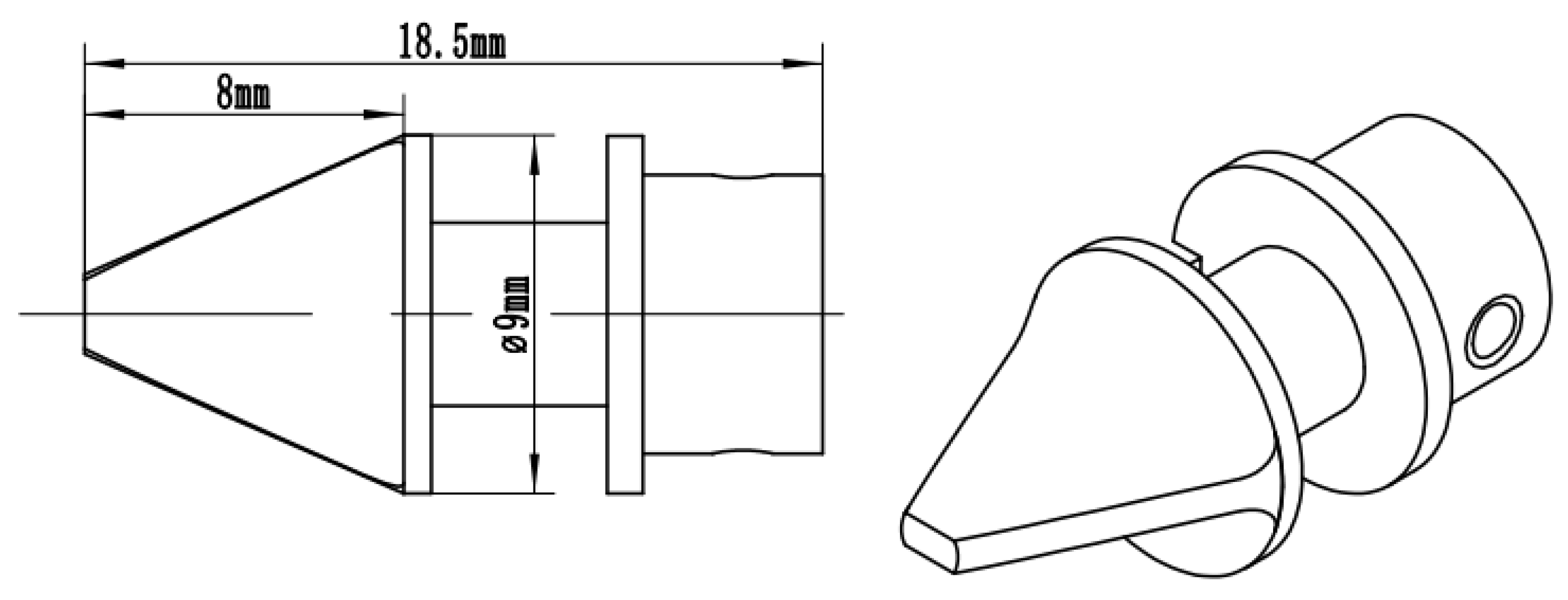
Figure 3.
Diagram of the jet-vane system’s structure.

Figure 4.
The jet-vane system of the AIM-9X missile.

Figure 5.
Physical model of the working fluid domain.

Figure 6.
Lateral force obtained by simulation.
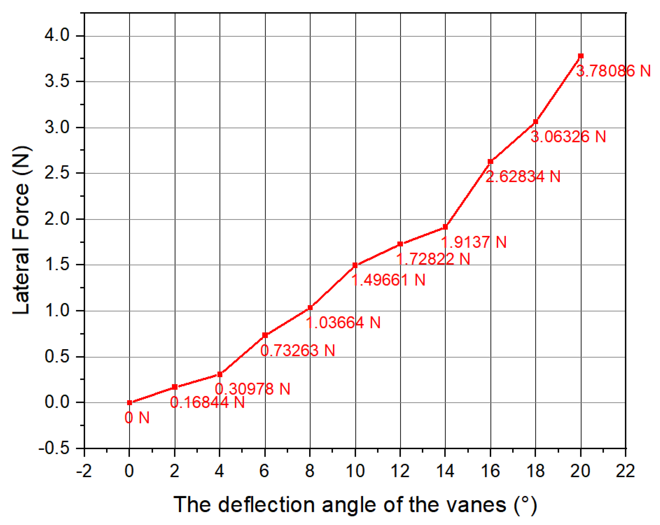
Figure 7.
Pressure contours on the surface of the jet vanes; (a) deflection 0°; (b) deflection 2°; (c) deflection 4°; (d) deflection 6°; (e) deflection 8°; (f) deflection 10°; (g) deflection 12°; (h) deflection 14°; (i) deflection 16°; (j) deflection 18°; and (k) deflection 20°.
Figure 7.
Pressure contours on the surface of the jet vanes; (a) deflection 0°; (b) deflection 2°; (c) deflection 4°; (d) deflection 6°; (e) deflection 8°; (f) deflection 10°; (g) deflection 12°; (h) deflection 14°; (i) deflection 16°; (j) deflection 18°; and (k) deflection 20°.

Figure 8.
Temperature contours on the surface of the jet vanes; (a) deflection 0°; (b) deflection 2°; (c) deflection 4°; (d) deflection 6°; (e) deflection 8°; (f) deflection 10°; (g) deflection 12°; (h) deflection 14°; (i) deflection 16°; (j) deflection 18°; and (k) deflection 20°.
Figure 8.
Temperature contours on the surface of the jet vanes; (a) deflection 0°; (b) deflection 2°; (c) deflection 4°; (d) deflection 6°; (e) deflection 8°; (f) deflection 10°; (g) deflection 12°; (h) deflection 14°; (i) deflection 16°; (j) deflection 18°; and (k) deflection 20°.

Figure 9.
Temperature contours of the gas flow; (a) deflection 0°; (b) deflection 2°; (c) deflection 4°; (d) deflection 6°; (e) deflection 8°; (f) deflection 10°; (g) deflection 12°; (h) deflection 14°; (i) deflection 16°; (j) deflection 18°; and (k) deflection 20°.
Figure 9.
Temperature contours of the gas flow; (a) deflection 0°; (b) deflection 2°; (c) deflection 4°; (d) deflection 6°; (e) deflection 8°; (f) deflection 10°; (g) deflection 12°; (h) deflection 14°; (i) deflection 16°; (j) deflection 18°; and (k) deflection 20°.
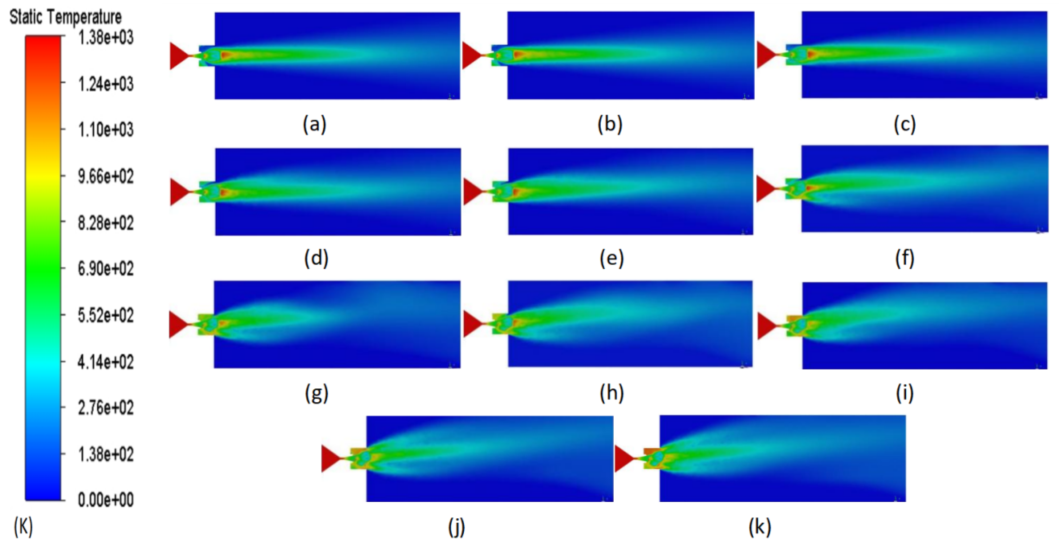
Figure 10.
Velocity contours of the gas flow; (a) deflection 0°; (b) deflection 2°; (c) deflection 4°; (d) deflection 6°; (e) deflection 8°; (f) deflection 10°; (g) deflection 12°; (h) deflection 14°; (i) deflection 16°; (j) deflection 18°; and (k) deflection 20°.
Figure 10.
Velocity contours of the gas flow; (a) deflection 0°; (b) deflection 2°; (c) deflection 4°; (d) deflection 6°; (e) deflection 8°; (f) deflection 10°; (g) deflection 12°; (h) deflection 14°; (i) deflection 16°; (j) deflection 18°; and (k) deflection 20°.

Figure 11.
System of 45 Steel jet vanes.

Figure 12.
System of alumina-ceramic jet vanes.

Figure 13.
System of tungsten–molybdenum-alloy jet vanes.

Figure 14.
Test equipment.

Figure 15.
Condition of the 45 Steel jet vanes after testing.

Figure 16.
Photograph comparing erosion in 45 steel jet vanes.

Figure 17.
Analysis of errors by laser scanning; (a) the measured value of a standard part; and (b) the design size of a standard part.
Figure 17.
Analysis of errors by laser scanning; (a) the measured value of a standard part; and (b) the design size of a standard part.

Figure 18.
Results of ablation measurements for the 45 Steel jet vanes; (a) jet vane 1; (b) jet vane 2; (c) jet vane 3; and (d) jet vane 4.
Figure 18.
Results of ablation measurements for the 45 Steel jet vanes; (a) jet vane 1; (b) jet vane 2; (c) jet vane 3; and (d) jet vane 4.

Figure 19.
Condition of alumina-ceramic jet vanes after testing.

Figure 20.
Photograph comparing erosion in alumina-ceramic jet vanes.

Figure 21.
Results of ablation measurements for alumina-ceramic jet vanes; (a) jet vane 1; (b) jet vane 2; (c) jet vane 3; (d) jet vane 4.
Figure 21.
Results of ablation measurements for alumina-ceramic jet vanes; (a) jet vane 1; (b) jet vane 2; (c) jet vane 3; (d) jet vane 4.

Figure 22.
The condition of tungsten–molybdenum-alloy jet vanes after testing.
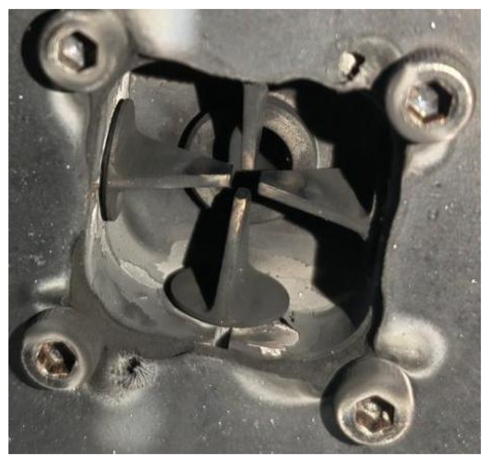
Figure 23.
Photograph comparing erosion in tungsten–molybdenum-alloy jet vanes.
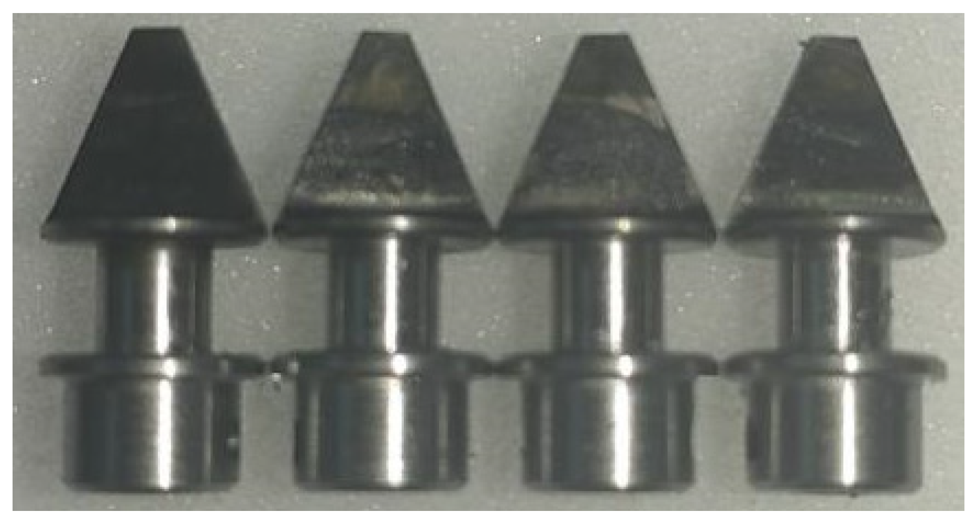
Figure 24.
Results of ablation measurements for tungsten–molybdenum-alloy jet vanes; (a) jet vane 1; (b) jet vane 2; (c) jet vane 3; and (d) jet vane 4.
Figure 24.
Results of ablation measurements for tungsten–molybdenum-alloy jet vanes; (a) jet vane 1; (b) jet vane 2; (c) jet vane 3; and (d) jet vane 4.

Figure 25.
Pressure curve of the combustion chamber.

Figure 26.
Lateral force curve of the test.

Figure 27.
Thrust curve of the test.

Figure 28.
Steering angle curve of the test.

Figure 29.
Gas flow visualization and temperature contours; (a) as flow image when the deflection angle is 0°; (b) temperature contour when the deflection angle is 0°; (c) gas flow image when the deflection angle is 20°; and (d) temperature contour when the deflection angle is 20°.
Figure 29.
Gas flow visualization and temperature contours; (a) as flow image when the deflection angle is 0°; (b) temperature contour when the deflection angle is 0°; (c) gas flow image when the deflection angle is 20°; and (d) temperature contour when the deflection angle is 20°.


Table 1.
Parameters of the solid rocket motor.
| Parameters of the Solid Rocket Motor | Values |
|---|---|
| Total gas temperature Tc/(K) | 1380 |
| Total pressure Pc/(MPa) | 8 |
| Specific heat ratio of gas k | 1.2 |
| Throat diameter Dt/(mm) | 2.5 |
| Pressure at the nozzle outlet Pe/(MPa) | 0.2 |
| Temperature at the nozzle outlet Te/(K) | 946.6 |
| Gas density at the nozzle outlet /(kg/m3) | 0.68 |
| Gas velocity at the nozzle outlet Ve/(m/s) | 1605.6 |
| Mach number at the nozzle exit Mae | 2.81 |
| Expansion ratio of nozzle | 7 |
| Thrust Fc/(N) | 50 |
Table 2.
Property parameters of the gas.
| Parameters of the Gas | Values |
|---|---|
| Total gas temperature Tc/(K) | 1380 |
| Molecular weight/(g/mol) | 26.885 |
| Specific heat capacity/(J/(Kg·K)) | 2975.3 |
Table 3.
Lateral force values under various grid settings.
| Size of the Grid | Number of Grids | Lateral Force (N) |
|---|---|---|
| 0.2 mm | 9,115,316 | 3.79 |
| 0.3 mm | 3,249,412 | 3.77 |
| 0.4 mm | 1,767,302 | 3.78 |
| 0.5 mm | 1,354,466 | 3.76 |
| 0.6 mm | 911,809 | 3.02 |
| 0.7 mm | 760,415 | 3.21 |
| 0.8 mm | 689,252 | 3.04 |
| 0.9 mm | 641,845 | 3.23 |
| 1 mm | 615,419 | 3.01 |
Disclaimer/Publisher’s Note: The statements, opinions and data contained in all publications are solely those of the individual author(s) and contributor(s) and not of MDPI and/or the editor(s). MDPI and/or the editor(s) disclaim responsibility for any injury to people or property resulting from any ideas, methods, instructions or products referred to in the content. |
© 2024 by the authors. Licensee MDPI, Basel, Switzerland. This article is an open access article distributed under the terms and conditions of the Creative Commons Attribution (CC BY) license (https://creativecommons.org/licenses/by/4.0/).
Share and Cite
MDPI and ACS Style
Zhang, G.; Feng, W.; Tan, Y.; Liu, Y.; Hui, W. Implementation and Verification of a Micro-Jet-Vane System of a Solid Rocket Motor for a Micro-Nano Satellite. Aerospace 2024, 11, 384. https://doi.org/10.3390/aerospace11050384
AMA Style
Zhang G, Feng W, Tan Y, Liu Y, Hui W. Implementation and Verification of a Micro-Jet-Vane System of a Solid Rocket Motor for a Micro-Nano Satellite. Aerospace. 2024; 11(5):384. https://doi.org/10.3390/aerospace11050384
Chicago/Turabian StyleZhang, Gang, Wen Feng, Youwen Tan, Yang Liu, and Weihua Hui. 2024. "Implementation and Verification of a Micro-Jet-Vane System of a Solid Rocket Motor for a Micro-Nano Satellite" Aerospace 11, no. 5: 384. https://doi.org/10.3390/aerospace11050384
Note that from the first issue of 2016, this journal uses article numbers instead of page numbers. See further details here.