
Self-Powered and Autonomous Vibrational Wake-Up System Based on Triboelectric Nanogenerators and MEMS Switch

 , and
, and 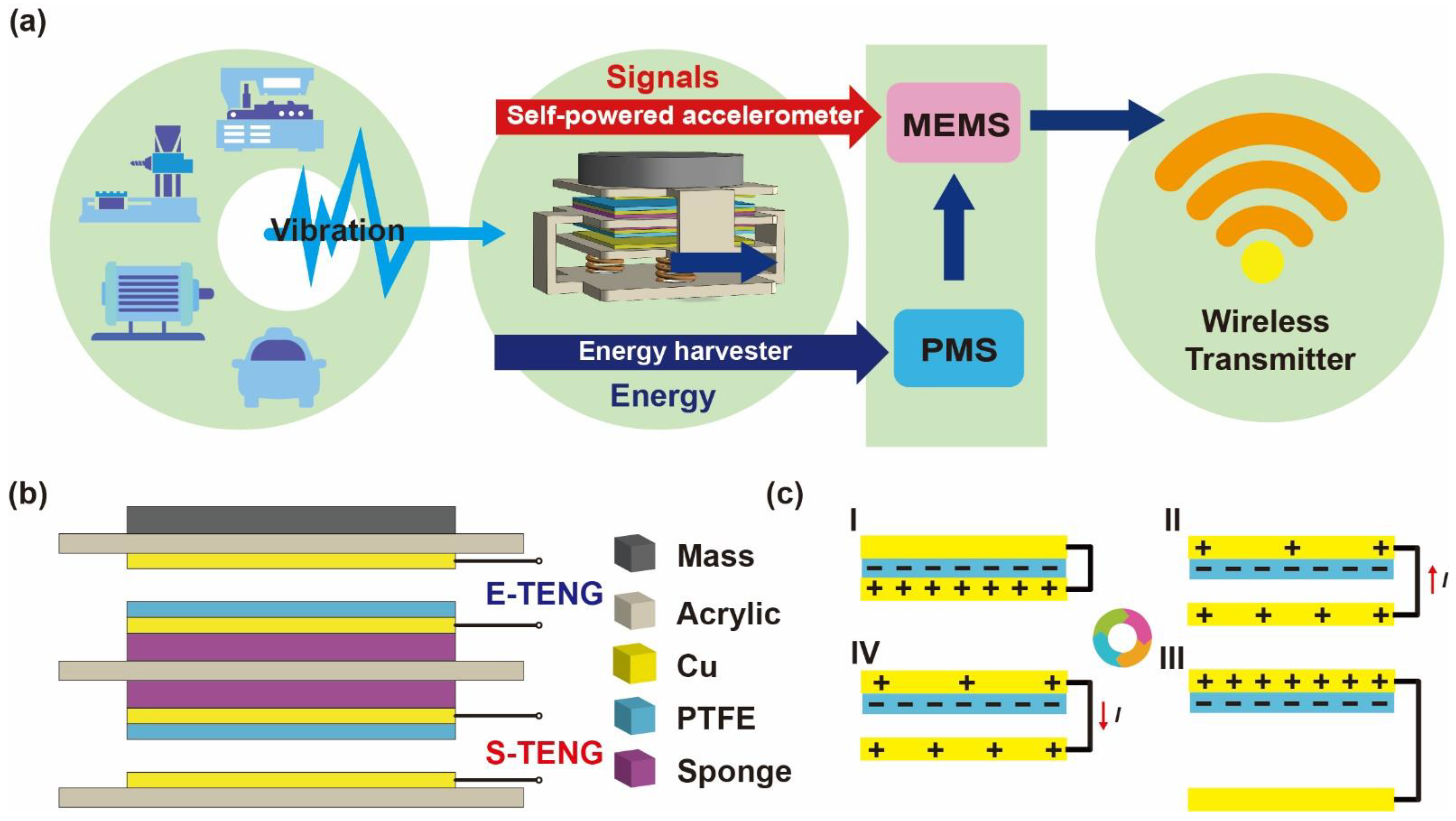
Abstract
:1. Introduction
2. Result and Discussion
2.1. System Framework and Working Mechanism of TENG
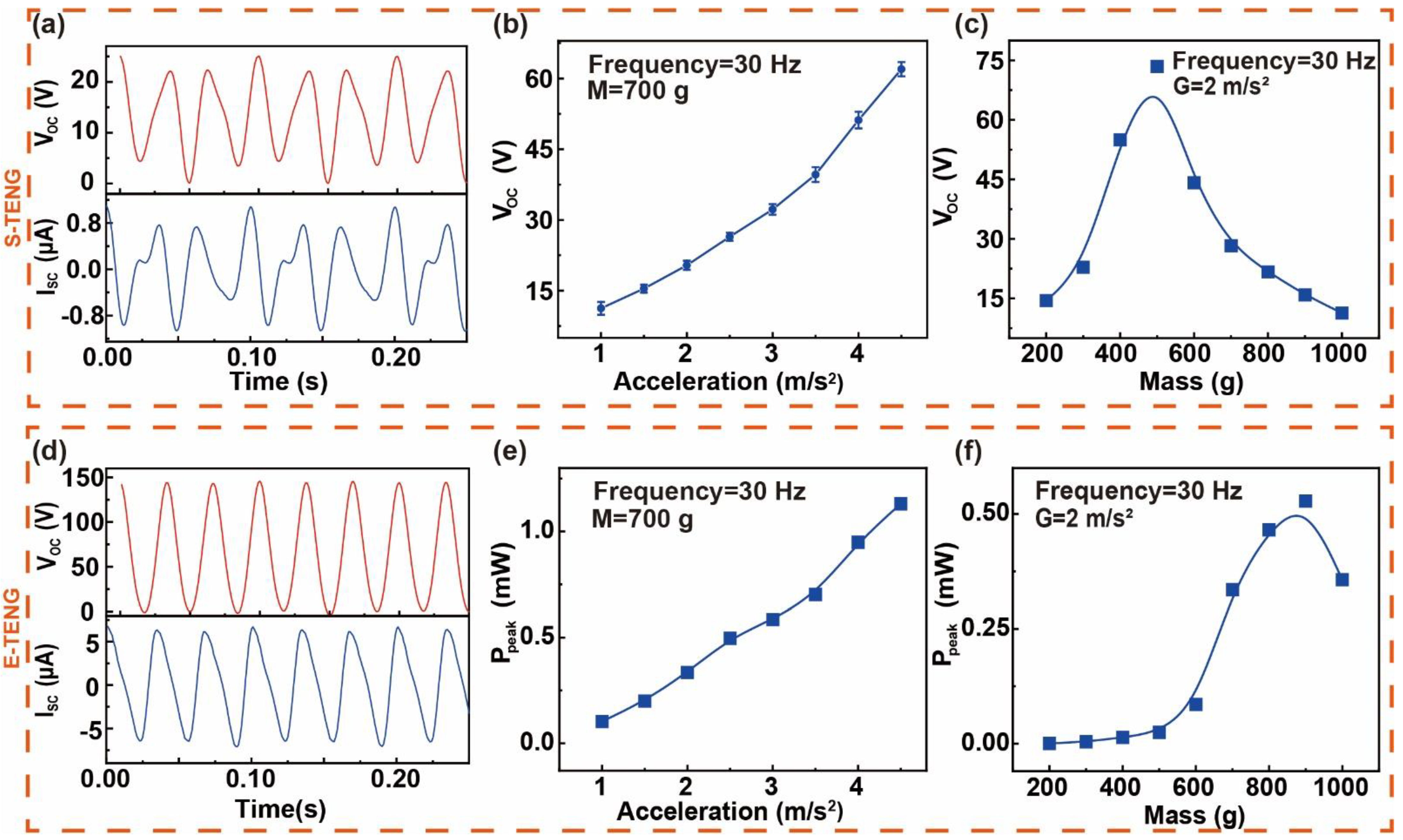
2.2. Output Characteristics of E-TENG and S-TENG
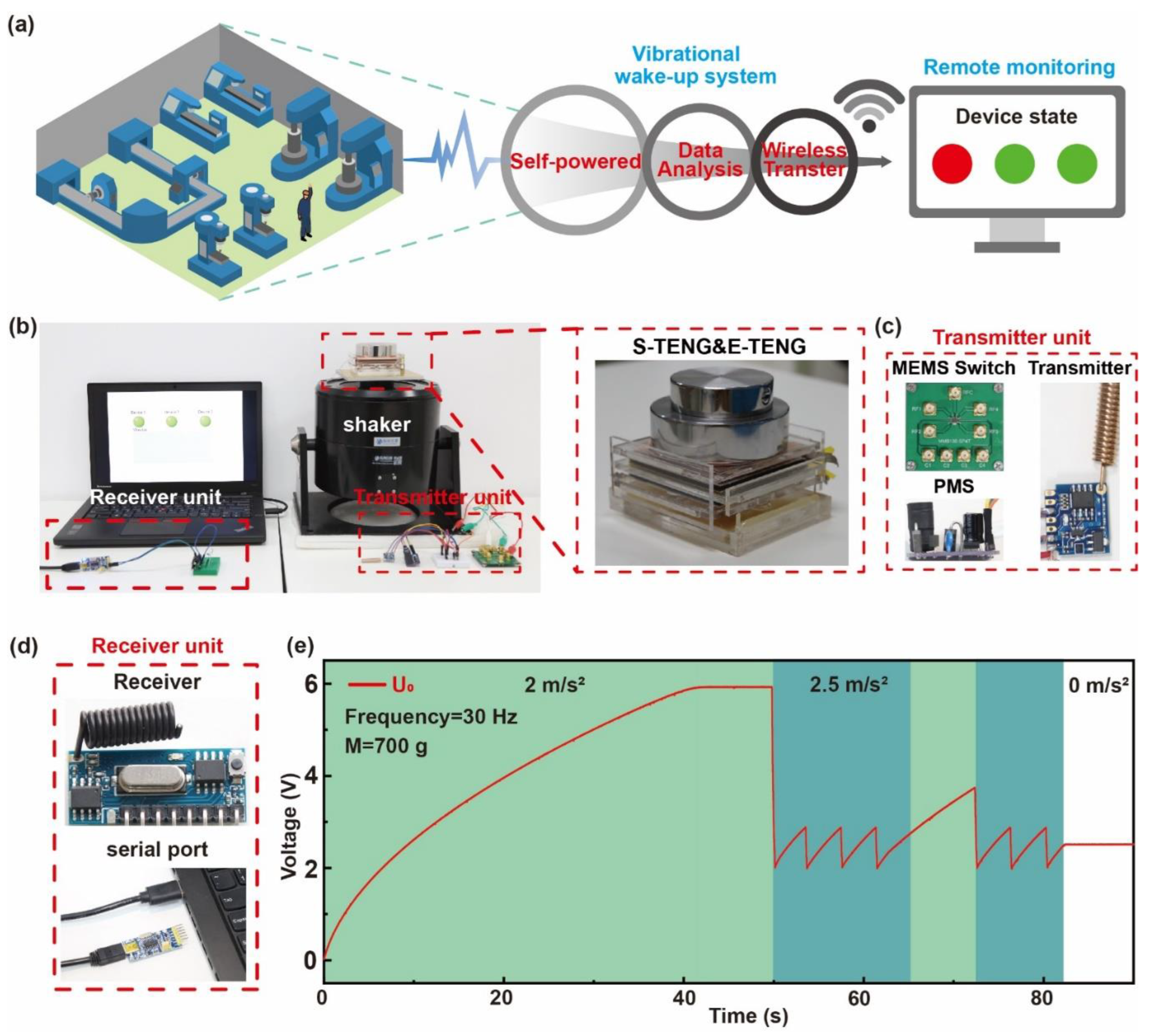
2.3. Working Principle and Performance of SAVWS
2.4. Working Principle and Performance of SAVWS
3. Materials and Methods
3.1. The Materials of Vibrational TENGs
3.2. The Fabrication of Integrated TENG
3.3. Measurement and Electronic Components
4. Conclusions
Supplementary Materials
Author Contributions
Funding
Institutional Review Board Statement
Informed Consent Statement
Data Availability Statement
Conflicts of Interest
References
- Quy, V.K.; Nam, V.H.; Linh, D.M.; Ban, N.T.; Han, N.D. A Survey of QoS-Aware Routing Protocols for the MANET-WSN Convergence Scenarios in IoT Networks. Wirel. Pers. Commun. 2021, 120, 49–62. [Google Scholar] [CrossRef]
- Said, O.; Al-Makhadmeh, Z.; Tolba, A. EMS: An Energy Management Scheme for Green IoT Environments. IEEE Access 2020, 8, 44983–44998. [Google Scholar] [CrossRef]
- Zeadally, S.; Shaikh, F.K.; Talpur, A.; Sheng, Q.Z. Design Architectures for Energy Harvesting in the Internet of Things. Renew. Sustain. Energy Rev. 2020, 128, 109901. [Google Scholar] [CrossRef]
- Zhu, G.; Pan, C.; Guo, W.; Chen, C.Y.; Zhou, Y.; Yu, R.; Wang, Z.L. Triboelectric-Generator-Driven Pulse Electrodeposition for Micropatterning. Nano Lett. 2012, 12, 4960–4965. [Google Scholar] [CrossRef]
- Wang, S.; Lin, L.; Xie, Y.; Jing, Q.; Niu, S.; Wang, Z.L. Sliding-Triboelectric Nanogenerators Based on in-Plane Charge-Separation Mechanism. Nano Lett. 2013, 13, 2226–2233. [Google Scholar] [CrossRef] [PubMed] [Green Version]
- Yang, Y.; Zhou, Y.S.; Zhang, H.; Liu, Y.; Lee, S.; Wang, Z.L. A Single-Electrode Based Triboelectric Nanogenerator as Self-Powered Tracking System. Adv. Mater. 2013, 25, 6594–6601. [Google Scholar] [CrossRef] [PubMed]
- Wang, S.; Xie, Y.; Niu, S.; Lin, L.; Wang, Z.L. Freestanding Triboelectric-Layer-Based Nanogenerators for Harvesting Energy from a Moving Object or Human Motion in Contact and Non-Contact Modes. Adv. Mater. 2014, 26, 2818–2824. [Google Scholar] [CrossRef]
- Wang, Y.; Wang, J.; Xiao, X.; Wang, S.; Kien, P.T.; Dong, J.; Mi, J.; Pan, X.; Wang, H.; Xu, M. Multi-Functional Wind Barrier Based on Triboelectric Nanogenerator for Power Generation, Self-Powered Wind Speed Sensing and Highly Efficient Windshield. Nano Energy 2020, 73, 104736. [Google Scholar] [CrossRef]
- Wang, Y.; Yu, X.; Yin, M.; Wang, J.; Gao, Q.; Yu, Y.; Cheng, T.; Wang, Z.L. Gravity Triboelectric Nanogenerator for the Steady Harvesting of Natural Wind Energy. Nano Energy 2021, 82, 105740. [Google Scholar] [CrossRef]
- Chen, H.; Xing, C.; Li, Y.; Wang, J.; Xu, Y. Triboelectric Nanogenerators for a Macro-Scale Blue Energy Harvesting and Self-Powered Marine Environmental Monitoring System. Sustain. Energy Fuels 2020, 4, 1063–1077. [Google Scholar] [CrossRef]
- Wang, Y.; Liu, X.; Chen, T.; Wang, H.; Zhu, C.; Yu, H.; Song, L.; Pan, X.; Mi, J.; Lee, C.; et al. An Underwater Flag-like Triboelectric Nanogenerator for Harvesting Ocean Current Energy under Extremely Low Velocity Condition. Nano Energy 2021, 90, 106503. [Google Scholar] [CrossRef]
- Wang, K.; Zhou, J.; Ouyang, H.; Chang, Y.; Xu, D. A Dual Quasi-Zero-Stiffness Sliding-Mode Triboelectric Nanogenerator for Harvesting Ultralow-Low Frequency Vibration Energy. Mech. Syst. Signal Process. 2021, 151, 107368. [Google Scholar] [CrossRef]
- Tan, D.; Zhou, J.; Wang, K.; Zhao, X.; Wang, Q.; Xu, D. Bow-Type Bistable Triboelectric Nanogenerator for Harvesting Energy from Low-Frequency Vibration. Nano Energy 2022, 92, 106746. [Google Scholar] [CrossRef]
- Chen, C.; Chen, L.; Wu, Z.; Guo, H.; Yu, W.; Du, Z.; Wang, Z.L. 3D Double-Faced Interlock Fabric Triboelectric Nanogenerator for Bio-Motion Energy Harvesting and as Self-Powered Stretching and 3D Tactile Sensors. Mater. Today 2020, 32, 84–93. [Google Scholar] [CrossRef]
- Fu, J.; Xia, K.; Xu, Z. A Triboelectric Nanogenerator Based on Human Fingernail to Harvest and Sense Body Energy. Microelectron. Eng. 2020, 232, 111408. [Google Scholar] [CrossRef]
- Xi, F.; Pang, Y.; Li, W.; Jiang, T.; Zhang, L.; Guo, T.; Liu, G.; Zhang, C.; Wang, Z.L. Universal Power Management Strategy for Triboelectric Nanogenerator. Nano Energy 2017, 37, 168–176. [Google Scholar] [CrossRef]
- Harmon, W.; Bamgboje, D.; Guo, H.; Hu, T.; Wang, Z.L. Self-Driven Power Management System for Triboelectric Nanogenerators. Nano Energy 2020, 71, 104642. [Google Scholar] [CrossRef]
- Zhou, H.; Liu, G.; Zeng, J.; Dai, Y.; Zhou, W.; Xiao, C.; Dang, T.; Yu, W.; Chen, Y.; Zhang, C. Recent Progress of Switching Power Management for Triboelectric Nanogenerators. Sensors 2022, 22, 1668. [Google Scholar] [CrossRef]
- An, X.; Wang, C.; Shao, R.; Sun, S. Advances and Prospects of Triboelectric Nanogenerator for Self-Powered System. Int. J. Smart Nano Mater. 2021, 12, 233–255. [Google Scholar] [CrossRef]
- Fu, X.; Xu, S.; Gao, Y.; Zhang, X.; Liu, G.; Zhou, H.; Lv, Y.; Zhang, C.; Wang, Z.L. Breeze-Wind-Energy-Powered Autonomous Wireless Anemometer Based on Rolling Contact-Electrification. ACS Energy Lett. 2021, 6, 2343–2350. [Google Scholar] [CrossRef]
- Xi, F.; Pang, Y.; Liu, G.; Wang, S.; Li, W.; Zhang, C.; Wang, Z.L. Self-Powered Intelligent Buoy System by Water Wave Energy for Sustainable and Autonomous Wireless Sensing and Data Transmission. Nano Energy 2019, 61, 1–9. [Google Scholar] [CrossRef]
- Wu, J.; Zheng, Y.; Li, X. Recent Progress in Self-Powered Sensors Based on Triboelectric Nanogenerators. Sensors 2021, 21, 7129. [Google Scholar] [CrossRef] [PubMed]
- Zhou, Q.; Pan, J.; Deng, S.; Xia, F.; Kim, T. Triboelectric Nanogenerator-Based Sensor Systems for Chemical or Biological Detection. Adv. Mater. 2021, 33, 1–21. [Google Scholar] [CrossRef] [PubMed]
- Jiang, M.; Lu, Y.; Zhu, Z.; Jia, W. Advances in Smart Sensing and Medical Electronics by Self-Powered Sensors Based on Triboelectric Nanogenerators. Micromachines 2021, 12, 698. [Google Scholar] [CrossRef] [PubMed]
- Wu, H.; Wang, J.; Wu, Z.; Kang, S.; Wei, X.; Wang, H.; Luo, H.; Yang, L.; Liao, R.; Wang, Z.L. Multi-Parameter Optimized Triboelectric Nanogenerator Based Self-Powered Sensor Network for Broadband Aeolian Vibration Online-Monitoring of Transmission Lines. Adv. Energy Mater. 2022, 12, 2103654. [Google Scholar] [CrossRef]
- Ugwiri, M.A.; Mpia, I.; Lay-Ekuakille, A. Vibrations for Fault Detection in Electric Machines. IEEE Instrum. Meas. Mag. 2020, 23, 66–72. [Google Scholar] [CrossRef]
- Li, W.; Liu, Y.; Wang, S.; Li, W.; Liu, G.; Zhao, J.; Zhang, X.; Zhang, C. Vibrational Triboelectric Nanogenerator-Based. IEEE/ASME Trans. Mechatron. 2020, 25, 2188–2196. [Google Scholar] [CrossRef]
- Akhtulov, A.; Ivanova, L. Vibration Analysis as an Auxiliary Tool for Monitoring the Safety and Viability of Production Equipment in Mechanical Engineering. IOP Conf. Ser. Mater. Sci. Eng. 2020, 971, 052084. [Google Scholar] [CrossRef]
- Liu, C.; Wang, Y.; Zhang, N.; Yang, X.; Wang, Z.; Zhao, L.; Yang, W.; Dong, L.; Che, L.; Wang, G.; et al. A Self-Powered and High Sensitivity Acceleration Sensor with V-Q-a Model Based on Triboelectric Nanogenerators (TENGs). Nano Energy 2020, 67, 104228. [Google Scholar] [CrossRef]
- Nguyen, T.; Dinh, T.; Phan, H.P.; Dau, V.T.; Nguyen, T.K.; Joy, A.P.; Bahreyni, B.; Qamar, A.; Rais-Zadeh, M.; Senesky, D.G.; et al. Self-Powered Monolithic Accelerometer Using a Photonic Gate. Nano Energy 2020, 76, 104950. [Google Scholar] [CrossRef]
- Gupta, R.K.; Dhakar, L.; Lee, C. Self-Powered In-Plane Accelerometer Using Triboelectric Mechanism. J. Phys. Conf. Ser. 2016, 773, 8–12. [Google Scholar] [CrossRef] [Green Version]
- Pang, Y.K.; Li, X.H.; Chen, M.X.; Han, C.B.; Zhang, C.; Wang, Z.L. Triboelectric Nanogenerators as a Self-Powered 3D Acceleration Sensor. ACS Appl. Mater. Interfaces 2015, 7, 19076–19082. [Google Scholar] [CrossRef] [Green Version]
- Tong, T.; Liu, G.; Lin, Y.; Xu, S.; Zhang, C. A Near-Zero Power Triboelectric Wake-Up System for Autonomous Beaufort Scale of Wind Force Monitoring. Nanoenergy Adv. 2021, 1, 6. [Google Scholar] [CrossRef]
- Zhang, C.; Dai, K.; Liu, D.; Yi, F.; Wang, X.; Zhu, L.; You, Z. Ultralow Quiescent Power-Consumption Wake-Up Technology Based on the Bionic Triboelectric Nanogenerator. Adv. Sci. 2020, 7, 1–10. [Google Scholar] [CrossRef] [PubMed]
- Davies, D.K. Charge Generation on Dielectric Surfaces. J. Phys. D Appl. Phys. 1969, 2, 1533–1537. [Google Scholar] [CrossRef]
- Zou, H.; Zhang, Y.; Guo, L.; Wang, P.; He, X.; Dai, G.; Zheng, H.; Chen, C.; Wang, A.C.; Xu, C.; et al. Quantifying the Triboelectric Series. Nat. Commun. 2019, 10, 1–9. [Google Scholar] [CrossRef] [PubMed] [Green Version]
- Wen, X.; Yang, W.; Jing, Q.; Wang, Z.L. Harvesting Broadband Kinetic Impact Energy from Mechanical Triggering/Vibration and Water Waves. ACS Nano 2014, 8, 7405–7412. [Google Scholar] [CrossRef]


Publisher’s Note: MDPI stays neutral with regard to jurisdictional claims in published maps and institutional affiliations. |
© 2022 by the authors. Licensee MDPI, Basel, Switzerland. This article is an open access article distributed under the terms and conditions of the Creative Commons Attribution (CC BY) license (https://creativecommons.org/licenses/by/4.0/).
Share and Cite
Lin, Y.; Qi, Y.; Wang, J.; Liu, G.; Wang, Z.; Zhao, J.; Lv, Y.; Zhang, Z.; Tian, N.; Wang, M.; et al. Self-Powered and Autonomous Vibrational Wake-Up System Based on Triboelectric Nanogenerators and MEMS Switch. Sensors 2022, 22, 3752. https://doi.org/10.3390/s22103752
Lin Y, Qi Y, Wang J, Liu G, Wang Z, Zhao J, Lv Y, Zhang Z, Tian N, Wang M, et al. Self-Powered and Autonomous Vibrational Wake-Up System Based on Triboelectric Nanogenerators and MEMS Switch. Sensors. 2022; 22(10):3752. https://doi.org/10.3390/s22103752
Chicago/Turabian StyleLin, Yuan, Youchao Qi, Jiaqi Wang, Guoxu Liu, Zhaozheng Wang, Junqing Zhao, Yi Lv, Zhi Zhang, Ning Tian, Mengbi Wang, and et al. 2022. "Self-Powered and Autonomous Vibrational Wake-Up System Based on Triboelectric Nanogenerators and MEMS Switch" Sensors 22, no. 10: 3752. https://doi.org/10.3390/s22103752