
Enhancement of Heat Transfer in a Microchannel via Passive and Active Control of a Jet Issued from the Circular Cylinder
The College of Mechanics and Materials, HoHai University, Nanjing 211100, China
*
Author to whom correspondence should be addressed.
Energies 2022, 15(21), 8287; https://doi.org/10.3390/en15218287
Submission received: 16 October 2022
/
Revised: 3 November 2022
/
Accepted: 3 November 2022
/
Published: 6 November 2022
(This article belongs to the Special Issue Numerical Simulation on Heat Transfer Technique)
Abstract
:The heat transfer enhancement of a jet issued from the circular cylinder placed in a three-dimensional microchannel at low Reynolds numbers were studied systematically by using the numerical simulation. The effects of the jet on thermal efficiency were evaluated by varying injection ratios (I) and jet angles (θ). The physical mechanism of heat transfer was revealed through the analyses of vorticity dynamic and temperature field. The results showed that the thermal efficiency was proportional to the injection ratio at Re = 100 and 200. However, at Re = 300, the thermal efficiency did not increase monotonically with the injection ratio, and the local maximum value of heat transfer efficiency, slightly less than the highest thermal efficiency, appeared at I = 1.5. This was a result of the jet inducing the vortex generated on the cylinder to become unstable. Furthermore, the change of jet angle had a better effect on heat transfer performance compared to the increase in the injection ratio. The separation point of the flow over cylinder and the vortices in the near field were adjusted by the change in jet angle. At the appropriate range of the jet angle, the wake vortices in the near field transitioned from quasi-steady to unsteady in the far field. The instability of wake vortices can disturb the thermal boundary layer near the wall so as to improve the heat transfer performance.
1. Introduction
The enhanced heat transfer technology is widely used in many traditional industrial fields, such as gas turbines, power batteries, hypersonic heating structures, and so on [1,2,3]. However, with the development of computers, the volume of electronic components with higher integration level has become smaller, the transmission frequency higher, and the amount of transmission information larger. Thus, the electronic module dissipates hundreds of watts of power per square micron, releasing a large amount of high heat flux [4]. This requires a very powerful cooling technology; hence, in recent years, researchers have begun to study the enhanced heat transfer technology in the microchannel flow and gradually applied this technology to electronic components [5,6,7]. For the enhanced heat transfer technology, there are two modes of in a micro cooling system, namely passive and active cooling [8].
In the passive micro-cooling system, a vortex generator (built-in obstacles such as pillars, etc.) is generally used to improve the heat transfer in the microchannel by disturbing the flow field. In most works about passive micro-cooling systems, the effects of cross-section shapes of vortex generator, blockage ratios, and Reynolds numbers on heat transfer were investigated [9,10,11]. The results show that regardless of cross-section shape of the obstacles, the thermal efficiency increases with the blocking ratio, and the trend of the change of the mechanical loss is reversed, and the heat transfer performance is improved with the decrease in the aspect ratio [12,13,14]. Meis et al. [15] found that combined with the economic benefits and thermal efficiency, the rectangle cylinder with a 1/2 aspect ratio rotating clockwise for 30° has a better heat transfer effect and less mechanical loss. Li et al. [16] analyzed the influence of two side-by-side, freely rotatable square cylinders on heat transfer in the range of Re = 5–300. Turki et al. [11] obtained the specific mathematical relationship between the Nusselt number and Reynolds number for the cross-section of square shape, as the blockage ratio is 1/4 and 1/8, respectively. To approach engineering practice, many studies began to focus on the three-dimensional numerical simulation of enhanced heat transfer in the microchannel [17,18,19]. Armellini et al. [20] found that a very complex three-dimensional flow structure appeared upstream and downstream of the cylindrical obstacle, which leads to mass transport along the spanwise direction and enhanced the disturbance of spanwise flow by alternately shedding vortices. The heat transfer is enhanced by the mixing between the mainstream flow and the wake vortices shedding from the built-in cylinder [21].
The active micro-cooling system has received much attention, and it needs to consume additional energy to improve heat transfer [22]. Active air cooling and passive air cooling were compared experimentally by Ren et al. [23], and the results showed that the thermal performance of active air cooling is the best. This cooling method has good thermal performance even under high charge- and discharge-rate conditions. Considering the convenience and energy consumption of the system, heat transfer through a steady jet was investigated in many studies [24,25,26,27,28]. Firstly, the effects of the jet on wake vortices from the cylinder have received more attention. Shi et al. [29] found that the jet had an obvious disturbance effect on the flow field, and Karthikeyan et al. [30] deeply studied the effect of a jet on vortex shedding from a cylinder. The results of Jung [31,32] showed that due to the length-diameter ratio of the cylinder and the microchannel wall bound, the disturbance of the wake vortices to the flow field was suppressed at a low Reynolds number (less than the critical Reynolds number ). However, combined with an active control of a steady jet, the favorable disturbance was improved in the microchannel. From the above research, it was found that the jet induction can indeed increase the mixing of the flow field, but the specific heat transfer effect was not considered in these studies. Some researchers further studied the specific effect of jet on heat transfer in microchannels. A single jet can significantly reduce the local temperature of heat source, but the effect on the whole channel is not obvious. A certain number of jet devices can reduce the whole temperature field, but with the increase in the number of jet inlets, the wall temperature at the bottom of the microchannel also appears to increase [33].
From the analysis above, the heat transfer in microchannel can be enhanced by the jet. Nevertheless, the effects of the jet velocity and the layout of jet on heat transfer performance and the related physical mechanisms need to be further studied. The flow and heat transfer in microchannels with active and passive control (a steady jet from the pillar) at a low Reynolds number (less than the critical Reynolds number ) are deeply studied in this paper. It focuses on the influence mechanism of the jet angle and jet velocity on the flow field and heat transfer, and we attempt to give more appropriate parameters about the jet angle and jet velocity. The thermal efficiency is discussed from the views of the flow field and the temperature field, mainly including the vortex generation and shedding, Nusselt number, and so on. The physical model and problem statement are discussed in Section 2. The mathematical formulation and numerical procedure are carried out in Section 3. The results are analyzed and discussed in Section 4, and the conclusions are given in Section 5.
2. Physical Model and Problem Statement
A cylinder pillar was placed in a three-dimensional, non-isothermal microchannel, and the jet issued from this pillar was used to enhance the heat transfer of the unsteady flow in the microchannel, as shown in Figure 1. The geometric model and size refer to Jung [31]. The microchannel was in length, in width, and in height, and a steady jet was injected through a narrow slit of along with the cylinder (). The model diagram is shown in Figure 1. Except that the bottom wall (A) behind the cylinder (), colored in red, was a constant heat wall, of which the temperature was kept at , the others were adiabatic walls. Meanwhile, the temperature of incoming flow was , and the injection ratio (I) is defined as the ratio between the jet velocity and the inlet velocity, according to Karthikeyan et al.’s study [30]. The jet angle () is defined as the angle between the jet slit and the positive direction of the X-axis in the study. The origin coordinate was located at the intersection point of the bottom centerline and the junction line of the heat source and the adiabatic wall, the positive direction of the X-axis was along the incoming flow direction, and the Y-axis and Z-axis were parallel to the width and height of the microchannel, respectively, as shown in Figure 1.
To analyze and compare the results in various cases uniformly, the physical quantities in this study had been transformed into dimensionless forms. The space coordinate , velocity component , and pressure were non-dimensionalized by the liquid density (), the cylinder diameter (), and inlet velocity (). The characteristic time is expressed as , and the dimensionless temperature is shown as . Since the property of water in practical engineering changed with temperature, we assumed that the specific heat capacity of water was constant (), and dimensionless viscosity () and thermal conductivity () were quadratic functions of temperature [15]:
where the values of coefficient in the above equation (in the range of temperature ) were given as follows:
In this study, three kinds of inlet velocities were taken into account, and the corresponding Reynolds numbers based on cylinder diameter were , respectively.
To analyze the heat transfer behavior, it was necessary to define thermal efficiency [15]. First of all, the time-averaged local heat flux of the nonadiabatic part of the bottom wall can be described by the dimensionless Nusselt number:
where Q was the heat flux density of the constant hot wall. The time interval between and must be large enough to avoid the dependence of the time-average value on the integration interval. The global time-averaged Nusselt numbers were defined as
According to the Nusselt number, the thermal efficiency was defined as follows:
where was used as a reference term indicating that the jet did not exist ().
3. Mathematical Formulation and Numerical Procedure
3.1. Governing Equations and Numerical Method
For unsteady, three-dimensional, incompressible laminar flow, the governing equations (continuity, momentum, and energy) can be expressed as follows [15]:
where the (inlet) Reynolds and Prandtl numbers were defined as [15]:
In this paper, the governing equations of three-dimensional, incompressible transient flow were solved by the finite volume method based on the open-source software OpenFoam. The velocity and pressure fields were coupled using the SIMPLEC algorithm, and the second-order upwind scheme was selected for solving the momentum and energy equations [34]. The first-order implicit time-marching scheme with a fixed time step of 1.2 × 10⁻⁶ s was employed for the transient solution [30]. All the computations were considered converged with a convergence threshold residual of 10 × 10−6 for both the continuity and velocities [25].
3.2. Boundary Conditions
Uniform inflow at the inlet:
The whole microchannel was surrounded by a thermal insulation wall except the bottom wall behind the cylinder:
The bottom wall (A) behind the cylinder was a constant heat wall:
Next, set free outflow at the outlet.
3.3. Numerical Verification and Grid Independence
The two-dimensional, unsteady laminar flow in the non-isothermal microchannel with a circular obstacle with the blockage ratio and was investigated to verify the numerical method [15]. It was found in Figure 2a that the cylinder excited the Karman vortex street in the microchannel, but the viscosity and thermal conductivity of water were related to temperature, and the whole vorticity distribution was not symmetrical about the centerline of the microchannel. From Figure 2b, these shedding vortices had a favorable effect on the overall heat transfer. It can also be qualitatively shown in Figure 3. It shows that the numerical method used in this paper was accurate and reliable through comparison with the results of the previous work [15].
The analysis of the grid independence was carried out. Table 1 showed the Nusselt numbers of microchannel corresponding to three sets of grids (coarse, medium, and fine sizes) when the Reynolds number was 300, and the injection ratio was 1. The mesh with medium size was chosen in the present study. The computational grids are shown in Figure 4.
4. Results and Discussion
The effects of the jet issued from the slot in the cylinder on heat transfer performance in the microchannel are investigated in this section. The bottom wall behind the cylinder was maintained at a fixed temperature, and the other walls were adiabatic (as shown in Figure 1). As a basic configuration, the cylinder was placed at the front end of the heat source, with a slit along the Z direction. The thermal efficiencies corresponding to different injection ratios and slit angles were calculated to evaluate the heat transfer performance. The relationship between flow field and heat transfer in the model was analyzed by means of the temperature, vorticity, three-dimensional vortex structure, and Nusselt number.
4.1. Effect of the Injection Ratio
4.1.1. Heat Transfer Performance
The local Nusselt numbers of the microchannel along the flow direction under different injection ratios as are shown in Figure 5. From the local Nusselt number shown in Figure 5, regardless of the Reynolds number and injection ratio, the local Nusselt number had a larger value on the cylinder () and gradually decreased along the flow direction. This result was consistent with Meis’s conclusion [15]. Along the flow direction, the local Nusselt number decreased sharply at but did not change significantly at . This showed that the effect of jet on heat transfer was local, and the heat flux mainly depended on the velocity of incoming flow when it exceeded the local jet area. The local Nusselt numbers at are shown in Figure 5a,c,e. From to , the local Nusselt number increased slightly after the flow passed through the cylinder and then weakened downstream of the cylinder. As , the local Nusselt number rose with the increase in the injection ratio, but the growth in the local Nusselt number became slow when the injection ratios were higher. This meant that the increases in the heat flux were also slowing down. With the increase in the Reynolds number, the local Nusselt number also increased, indicating that the effect of the jet on heat transfer was more significant in the cases of lager Reynolds numbers, especially at .
The local Nusselt numbers at , as shown in Figure 5b,d,f, were larger than those at . As , the local Nusselt number at had no obvious changes with the injection ratio. Especially when , the local Nusselt numbers almost overlap. When , it was found that the local Nusselt number fluctuated violently near at . It could be seen that the crest value of local Nusselt number for even exceeded that for . This showed that when the injection ratio was , the mixing of the flow field was the largest at . This showed that I = 1.5 was a critical injection ratio parameter.
The influence regions of the jet can be more clearly reflected in Figure 6. With the increase in the injection ratio, the values of the local Nusselt number at were also increased regardless of Reynolds number. The local Nusselt number had “double peaks” near and in most cases. However, the values of the “double peaks” decreased with the increase in the injection ratio. As the Reynolds number increased, the local Nusselt number was enhanced, especially at the bilateral peaks. It can be found from Figure 6 that the whole local Nusselt number was symmetrical about , indicating that the jet effect was symmetrical about . As and , the local Nusselt number had four peaks along the Y direction. All in all, the Reynolds number mainly affected the local Nusselt numbers on two sides of the cylinder in the form of the passive control, and the local Nusselt number at the mid-plane () was determined by the active jet. Nevertheless, the heat transfer effect of the active jet interfered with the passive control effect.
As shown in Figure 7, the thermal efficiency increased with the increase in the injection ratio as . It can be concluded from Figure 7 that the thermal efficiency increased with the increase in the Reynolds number, which was in line with Karthikeyan’s conclusions: the thermal efficiency of active control can be improved by increasing the momentum coefficient of the jet as [30]. The changing trends of thermal efficiencies with injection ratio were the same at , and they exhibited almost linear growth trends. At a low Reynolds number, the thermal efficiency of the microchannel could be improved by increasing the injection ratio. However, considering the additional energy required for active control, it was necessary to select an appropriate injection ratio. However, when and , the thermal efficiency reached a turning point (first increasing and then decreasing), and the growth rate of the thermal efficiency was the largest. At the moment, the interaction between jet and flow over the cylinder greatly increased the heat transfer. This was the same as the above conclusion in Figure 6c. For , the thermal efficiency at was slightly smaller than the thermal efficiencies at I = 3.5 and I = 4.0. Given all of this, it is a more appropriate choice that the injection ratio is taken as 1.5.
4.1.2. Physical Mechanisms of Flow and Heat Transfer
According to the above analysis, the vorticity contours at were selected to analyze the flow field (in Figure 8). The flow was highly symmetrical, and a pair of vortices was attached to the cylinder surface, namely the main vortices generated by the incoming flow over the cylinder. Meanwhile, a pair of secondary vortices caused by the jet appeared at the slit, and the secondary vortices increased with the injection ratios of the jet. The secondary vortices caused by the jet led to the local flow field mixing and enhanced the local behavior of heat transfer. This was the cause of the “double peaks” in the local Nusselt number curves in Figure 6a–c.
The strength of the secondary vortices caused by the jet increased with the injection ratio. There were three different flow patterns in the microchannel: first, the strength of the secondary vortices generated by the jet are smaller than the main vortices generated on the cylinder (); second, the main vortex and the secondary vortex had the same effect (); third, the strength of the secondary vortex was larger than that of the main vortex (). When the main vortex was dominant, the strength of secondary vortices appearing in the region between a pair of main vortices was very small. With the increase in the injection ratio, the secondary vortex generated by the jet was dominant. When , although the flow also belonged to these three flow modes, the main vortex and secondary vortex interacted more obviously and became unstable compared with the cases at 200. When , it was found that the secondary vortices and the main vortices were no longer independent, but they interacted with each other. The secondary vortices interfered with the main vortices and made them twist as and . This strong interaction between the jet vortex and the main vortex was also found in Feng et al.’s study [35,36]. The twisted main vortex enhanced the mixing of the flow field and the disturbance of the thermal boundary layer. As , the secondary vortices gradually became larger, and the main vortices were weakened by the jet. This phenomenon that the overall instability and vortex shedding can be suppressed through the jet was reflected in the research of Mishra et al. The jet can even make the main vortex disappear at the appropriate jet strength [37].
According to the Q criterion [38], the three-dimensional vortex structures corresponding to at are presented in Figure 9a–e, respectively. The horseshoe vortex, which surrounded the cylinder, appeared at the leading edge of two ends of the cylinder due to the upper and lower walls of the microchannel. The horseshoe vortices generated at the intersection of the cylinder and the upper and lower walls are indicated by MV1 and MV2 in Figure 9. The evolution of the vortex structure in the middle part of the cylinder was similar to the two-dimensional flow over the circular cylinder. The reason was that the flow around the finite cylinder with a small aspect ratio was bound by the upper and lower walls [39]. The main vortices shedding from the cylinder and the secondary vortex generated by the jet are denoted by CV and JV in Figure 9, respectively. Without the jet control, the main vortices on both sides of the circular cylinder paralleled with the centerline of the microchannel. It can be seen from Figure 9b–e that there were significant interactions between the main vortices and the jet. At , the main vortex was twisted and became unstable in the flow field due to the jet although the strength of the secondary vortex generated by the jet was low. As the injection ratio increases to 2, the main vortices were suppressed by the secondary vortex generated by the jet, and the strengths of the wake vortices were the lowest in the cases for the jet control. Therefore, the heat transfer effect also declined at this time. As the injection ratio continued to increase, the main vortex was gradually weakened, but the secondary vortex generated by the jet steadily became larger. At the high injection ratio, the main vortex and the secondary vortex tended to coalesce. Thus, the mixing of flow field was also enhanced under the dominant influences of the active jet.
Through the above analyses of vorticity field, it was known that when 200, the heat transfer effect increased with injection ratio because the secondary vortices generated by the jet were enhanced continuously. When , different phenomena appeared in the flow field, so the temperature contours had different features accordingly. They are presented in Figure 10. The heat transfer mechanisms of the jet that issued from the circular pillar can be mainly divided into two categories: the jet’s directly borne heat and the mixing enhancement induced by the wake vortices. As shown in Figure 10a,c,d, the low temperature in the center of microchannel was caused by the jet, which carried away the relative hot fluid. From Figure 10b, it can be seen that the hot fluid segments on both sides of the central jet were caused by the vortices generated by the cylinder at , which caused the mixing of the hot fluid and cold fluid. With the increase in the injection ratio, the influence range of central low temperature was also gradually increased except the case of . At , the cold fluid in the center of microchannel was broken into smaller segments by the wake vortices. These cold segments penetrate the thermal boundary layer and move downstream due to the interaction of wake vortices and thermal boundary layer, which increases the interface area between the hot and cold fluids and enhances the heat transfer performance. At the same time, the hot fluid convolutes upward from the thermal boundary layer to the center of the microchannel. The region with a large number of hot fluid segments occurred in the center of microchannel. The unstable wake vortices helped to bring the hot fluid from the wall of the channel to the center of the channel so as to facilitate heat exchange. This revealed the physical mechanisms by which the heat exchange rates were the highest at due to the twisted main vortices.
The temperature contours downstream of the cylinder were shown to illustrate the effects of the central jet and the vortices shedding from the circular cylinder on the temperature fields in Figure 11. According to the analyses of the vorticity contour, the main vortices generated on the cylinder at Re = 100 and 200 were gradually suppressed with the increase in the injection ratio. It was found that the feature of fluid temperature distribution in the planes on the both sides of the circular cylinder was consistent with those in the center plane, so only the temperature contours at Y = 0.8 are shown in Figure 11a,b. At Re = 300, the strength of vortices near the trailing edge of the cylinder was relatively higher, and a different phenomenon appeared in the flow field. The temperature contours had different features accordingly. Therefore, the temperature contours in the center plane and both sides of the circular are shown, respectively. From Figure 11, it was found that the thickness of the thermal boundary layer on the bottom wall become relatively thinner as the Reynolds number increases under the same injection ratio by comparing the temperature contours at different Reynolds numbers, which matched our heat transfer efficiency in Figure 7. At Re = 100 and 200, the thickness of the thermal boundary layer was reduced with the increase in the injection ratio.
The temperature contours at the Y = 0 and 0.8 downstream of the cylinder for Re = 300 are shown in Figure 11c,d. The temperature behind the cylinder gradually increased with the distance from the heat source. The temperature changes along the Z direction at the center of the microchannel can be seen in Figure 11c. The hot fluids are transferred downstream by the active jet. With the increase in the injection ratio, the low-temperature region steadily expanded, and the thickness of heat boundary layer was reduced. As shown in Figure 11d, the fluid temperature variations in the planes on the both sides of the circular cylinder with the injection ratio were different from those in the center plane. The vortices generated by the cylinder, which were distributed on both sides of the circular cylinder from Figure 8, interacted with the thermal boundary layer and brought the heat from the bottom wall into the central fluid. It can be seen that when the injection ratio was 1.5, the thickness of the thermal boundary layer on the bottom wall was relatively thinner. This was because the vortices in the flow field are the most chaotic in this case. These vortices constantly disturbed the thermal boundary layer, which strengthened the heat transfer. However, at , 2.0, and , the developments of the thermal boundary layer were obvious. Therefore, the injection ratio of was a more appropriate choice to improve the heat transfer effect.
In most cases, with the increase in the injection ratio, the effect of passive control (vortices shedding from the cylinder) on heat transfer decreases gradually, while the effect of active jet control on heat transfer increases. For a cooling system, only using the circular cylinder fixed in the center of the microchannel as control strategy, its heat transfer effect was not very good because the vortices shedding from the cylinder was suppressed by the upper and lower walls. Although the jet of the high injection ratio can enhance the heat transfer flux, it also consumed more energy because of the active control. The temperature change caused by the jet is more obvious, especially in the center of microchannel. The existence of the jet made the high-temperature fluid move downstream and thus improved the heat transfer. The effect of the jet strength on heat transfer was mainly reflected in the near-field region rather than in the far-field region. This was also in line with Jung’s conclusion [32] that the effect of heat transfer near the jet port is obvious. However, when the injection ratio , the passive control and active jet control were organically combined to make the cooling system not only have higher heat transfer effect but also consume less energy. The jet of the appropriate injection ratio can induce the vortices shedding from the cylinder to become unstable, which destroys the thermal boundary layer near the wall, so as to improve the heat transfer effect.
4.2. Effect of the Jet Angles
4.2.1. Heat Transfer Performance
According to the above analysis, the instability of the wake vortices caused by the jet pointing backwards in the cylinder enhanced the heat transfer. Mishra et al. found that the jet angle had an influence on the interaction between the primary vortex and the secondary vortex [37]. Therefore, the impacts of the jet angle on the mixing of wake vortices and heat transfer performance deserved investigation. In this study, the jet angle was defined as the angle between the centerline of the slit and the positive direction of the X-axis. The heat transfer performances corresponding to different jet angles are analyzed in the following section. The injection ratios were all taken as for different injection angles according to the preceding analyses in this section. The jet angles were chosen every 30° in Figure 12. From Figure 12, the changes of jet angle can greatly affect the thermal efficiency, and it was found that the values of the thermal efficiency were symmetrical, about because the whole calculation model was symmetrical with respect to the Y-axis. It was not difficult to find that the variations of the thermal efficiency with the jet angles at and were more obvious than those at . Therefore, for the analysis of different jet angles, this study only focused on the counterclockwise angle.
In the range of , the jet angles were selected every 15° in order to obtain the optimal angle for different Reynolds numbers () in Figure 13. Regardless of the Reynolds number, there was a maximum value between . It was found from Figure 13 that when and , the changes of angle had little effect on the thermal efficiency. When , the jet angle had a significant effect on the heat transfer, and the maximum thermal efficiency could be increased to 134%. When , the heat transfer enhancement at was smallest. Combined with energy utilization rate and heat transfer effect, the regulation of the jet angle was superior to the increase in jet velocity in order to improve the thermal efficiency.
The local Nusselt numbers under different jet angles at Y = 0 and are presented in Figure 14. In the middle plane of the microchannel, the local Nusselt numbers were relatively close to each other in the far field, but the peak values of the local Nusselt numbers corresponding to the cases of were larger than those for , as shown in Figure 14a. The occurrence positions of the peak values of the local Nusselt numbers for different jet angles were slightly different, and there was a large second peak near the rear edge of the cylinder as , which is different from other cases. The local Nusselt number in the two side planes of the cylinder (i.e., Y = 1.5) is shown in Figure 14b. When the jet angle , the local Nusselt numbers at Y = 1.5 were larger than those for other jet angles in most positions along the X axis, and the local Nusselt number for was the largest. The local Nusselt numbers on the planes of the near field (X = 1) and the far field (X = 15) perpendicular to the inflow are demonstrated in Figure 14c,d, respectively. The local Nusselt numbers on the planes perpendicular to the inflow were not symmetrical with respect to Y = 0 due to the unilateral jet used in the present study. In the near field (X = 1), the differences of the local Nusselt numbers for different jet angles only appeared on as shown in Figure 14c, and the main characteristic was that the peak positions shifted with jet angles although the peak intensities of the local Nusselt numbers were almost equivalent. In the far field (X = 15), the differences of the local Nusselt numbers at each position were more significantly increased with jet angles than in the near field. It can be found from Figure 14d that the local Nusselt numbers corresponding to were the largest among all the jet angles and were maintained at a high value, especially in the region of . Therefore, the optimal heat transfer effect of the microchannel can be achieved as jet angle .
4.2.2. Physical Mechanisms of Flow and Heat Transfer
In the following sections, the physical mechanisms of flow and heat transfer corresponding to different jet angles were analyzed from the views of vorticity dynamic and temperature fields point. Figure 15 depicts the vorticity contours for different jet angles at and . At , the strength of wake vortices for different jet angles was not high and stable, and the transverse spacing of vortices shedding from the cylinder for was larger than that for other jet angles, as shown in Figure 15a. As , the strength of wake vortices was enhanced, and the ribbon vortices for became unstable in the far field, as shown in Figure 15b. It was clear that the strength of the wake vortices increased with the Reynolds number, and the distribution range and hydrodynamic instability of wake vortices can be regulated by changing the jet angle. These analyses revealed the reasons that the thermal efficiency of was the lowest, and the heat transfer effect was better at regardless of and in Figure 12 and Figure 13.
From the thermal efficiency in Figure 12, the heat transfer effect at was the optimal, so we mainly analyzed the flow and heat transfer mechanism in this case. First, the vorticity fields for = ±60° and = ±120°, as shown in Figure 16, were compared to analyze the impact of the clockwise and counterclockwise jet angle on the heat transfer performance of the microchannel. When = ±60°, the jet had hardly any effect on the location of the separation point of the main vortex generated on the cylinder and only adjusted the transverse spacing and the strength of the ribbon vortex structure with alternate positive and negative vorticity. When ±120°, the main vortex generated on the side with the jet was detached from the cylinder surface behind the secondary vortex generated by the jet, and the transverse spacing of the strip vortex in near field and the strength of wake vortices were larger than ±60°. The wake vortices became unstable in the far field with the increase in transverse spacing of the strip vortex in the near field. By comparison, it can be found that the distribution features of the wake vortices did not vary with the positive and negative direction of the jet angle but changed obviously with the magnitude of the jet angle. This explains the reason that the thermal efficiency for different angles was symmetric with respect to 0° in Figure 12.
In order to analyze the vorticity fields for different jet angles, the jet angles of 90°, 105°, 135°, and 180° were chosen, according to the variation of thermal efficiency in Figure 13. In the jet angle range from 90° to 180°, the changes of the jet angle adjusted the separation point of the flow over the cylinder, and the transverse spacing of the vortices in the near field and the strength of wake vortices were changed accordingly. As , the wake vortices in the near field transitioned from quasi-steady to unsteady in the far field, and the disturbance range of wake vortices with multiple strips was enhanced obviously compared with the jet angle of 0° (Figure 8). The instability of wake vortices increased the mixing of the flow field and improved the heat transfer performance. When the jet angle exceeded 120°, the wake vortices were almost quasi-steady or steady, and the disturbance range of the vortex structure decreased gradually with the increase in the jet angle. As , the instability of vortex in the far field was the most intense, indicating that the mixing of flow was powerful, so the heat transfer effect was the best.
Comparing Figure 17a,b, it was found that the strip vortex structure close to the wall had greater strength. This showed that the three-dimensional characteristics of wake vortices were remarkable. The three-dimensional vortex structure at is shown in Figure 18, where the arrow indicates the jet direction. Compared with Figure 9a, the horseshoe vortex appearing at the junction of the cylinder and walls became larger after changing the jet angle. The horseshoe vortices and the vortices shedding from the central part of cylinder caused the occurrence of wake vortices with multiple strips in Figure 17. From Figure 18a–c, the location of separation points of the main vortex generated on the side with the jet coincided with the jet port at , 105°, 135°. This demonstrates that the jet caused the separation point of flow over the cylinder to move upward. The transverse spacing of the strip vortex in the near field was increased because the oblique jet impinged the horseshoe vortices and the vortices generated on the cylinder. Thus, the distribution characteristics of the wake vortex, which tended to move towards both sides of the cylinder, were altered by using the oblique jet. Finally, the vortices with high transverse spacing in the near field became unstable in the far field, which strengthened the heat transfer.
The temperature contours for different jet angles at Y = 1.5 are depicted in Figure 19. The thermal boundary layers downstream of the cylinder were developed along the X direction. The cold and hot fluids in the microchannel can be mixed under the action of the vortices shedding from the cylinder, and the wake vortices were able to hinder the development of the thermal boundary layer. According to the above analysis of vortex dynamic, the transverse spacing of the strip vortex in near field and the instability of wake vortices in far field were changed with the jet angles. From Figure 19, it can be seen that the heat transfer effect was most obvious in the near field because the strength of vortices near the trailing edge of the cylinder was relatively higher for every jet angle. The wake vortices were damped along the X direction due to the diffusion, which led to the development of thermal boundary layer. However, as , the instability of vortex in the far field strengthened the mixing phenomenon of the flow field and slowed down the increase in the thickness of the thermal boundary layer. The depth of the thermal boundary layer corresponding to the jet angle of 105° was the thinnest, indicating that the heat transfer effect was the best. As shown in Table 2, the thermal efficiency for was 1.335, which increased by 20.8 % over the thermal efficiency. For other jet angles, the thickness of thermal boundary layer increased obviously along the downstream due to the quasi-steady wake vortices decaying gradually along the downstream.
5. Conclusions
The heat transfer of a cooling system combining passive and active control in the microchannel at low Reynolds numbers was studied in this paper. A jet issued from the circular cylinder placed in the microchannel was employed for this cooling system. The active jet control can interact with the passive control (vortices shedding from the cylinder) to regulate the heat transfer performance. Different injection ratios and jet angles were considered. Finally, the optimal control strategies were obtained by analyzing the flow mechanism and thermal efficiency. The main conclusions are as follows:
By comparing the heat transfer characteristics of the jet pointing backwards in the cylinder corresponding to different injection ratios (I) and Reynolds numbers, for the same injection ratio, the thermal efficiencies of the microchannel for were better than those for , and the thermal efficiency of the microchannel increased with the injection ratio as . However, the thermal efficiency at did not increase monotonically with the injection ratio. As , the thermal efficiency increased about 20% with respect to and was slightly less than the thermal efficiencies at I = 3.5 and I = 4.0. The injection ratio of was an optimal choice to enhance the heat transfer. This is because the jet with the appropriate injection ratio can induce the flow over the cylinder to become unstable, which disturbs the thermal boundary layer near the wall, so as to improve the heat transfer enhancement.
The heat transfer performances in the microchannel cooling system with different jet angles in the range of were also investigated. It was found that although the values of the thermal efficiency did not vary with the positive and negative direction of jet angle, the magnitude of changes of the jet angle can greatly affect the thermal efficiency. The changes of the jet angle can adjust the separation point of the flow over the cylinder and the transverse spacing and strength of the vortices in the near field. As , the wake vortices in the near field transitioned from quasi-steady to unsteady in the far field, and the disturbance range of wake vortices with multiple strips were obviously enhanced. As , the instability of the vortex in the far field was the most intense. The thermal efficiency increased by 34% as and . Above all, combined with the energy utilization rate and heat transfer effect, the regulation in jet angle was superior to the increase in the injection ratio in order to enhance the thermal efficiency.
Author Contributions
Conceptualization, Z.X.; methodology, Z.X.; software, Z.X. and X.K.; validation, X.K. and J.C.; formal analysis, X.K. and J.C.; writing—original draft preparation, X.K.; writing—review and editing, X.K. and J.C.; supervision, Z.X. All authors have read and agreed to the published version of the manuscript.
Funding
This work was supported by the National Natural Science Foundation of China (Grant No. 11872174), the Fundamental Research Funds for the Central Universities (Grant No. B200202236), and Key Laboratory of Port, Waterway, & Sedimentation Engineering Ministry of Communications, PRC (Yk220001-2).
Institutional Review Board Statement
Not applicable.
Informed Consent Statement
Not applicable.
Data Availability Statement
Not applicable.
Conflicts of Interest
The authors declare no conflict of interest.
References
- Deng, H.; Teng, J.; Zhu, M.; Qiang, X.; Lu, S.; Jiang, Y. Overall cooling performance evaluation for film cooling with different winglet pairs vortex generators. Appl. Therm. Eng. 2022, 201, 117731. [Google Scholar] [CrossRef]
- Babar, H.; Ali, H.M. Towards hybrid nanofluids: Preparation, thermophysical properties, applications, and challenges. J. Mol. Liq. 2019, 281, 598–633. [Google Scholar] [CrossRef]
- Wu, F.; Li, L.; Wang, J.; Fan, X.; Du, C. Numerical investigations on flow and heat transfer of swirl and impingement composite cooling structures of turbine blade leading edge. Int. J. Heat Mass Transf. 2019, 144, 118625. [Google Scholar] [CrossRef]
- Tuckerman, D.B.; Pease, R.F.W. High-Performance Heat Sinking for VLSI. IEEE Electron Device Lett. 1981, 2, 126–129. [Google Scholar] [CrossRef]
- Dadvand, A.; Hosseini, S.; Aghebatandish, S.; Khoo, B.C. Enhancement of heat and mass transfer in a microchannel via passive oscillation of a flexible vortex generator. Chem. Eng. Sci. 2019, 207, 556–580. [Google Scholar] [CrossRef]
- Ismael, M.A. Forced convection in partially compliant channel with two alternated baffles. Int. J. Heat Mass Transf. 2019, 142, 118455. [Google Scholar] [CrossRef]
- Ebaika, J.A.; Shuja, S.Z.; Yilbas, B.S.; Al-Qahtani, H. Microchannel flow and heat transfer enhancement via ribs arrangements. Proc. Inst. Mech. Eng. Part E J. Process Mech. Eng. 2022, 236, 668–684. [Google Scholar] [CrossRef]
- Kakac, S.; Shah, R.K.; Aung, W. Handbook of Single-Phase Convective Heat Transfer; Wiley-Interscience: New York, NY, USA, 1987; p. 408. [Google Scholar]
- Rahnama, M.; Moghaddam, H.H. Numerical investigation of convective heat transfer in unsteady laminar flow over a square cylinder in a channel. Heat Transf. Eng. 2005, 26, 21–29. [Google Scholar] [CrossRef]
- He, J.; Deng, Q.; Xiao, K.; Feng, Z. Impingement Heat Transfer Enhancement in Crossflow by V-Shaped Protrusion Vortex Generator. Heat Transf. Eng. 2022, 1–26. [Google Scholar] [CrossRef]
- Turki, S.; Abbassi, H.; Nasrallah, S.B. Two-dimensional laminar fluid flow and heat transfer in a channel with a built-in heated square cylinder. Int. J. Therm. Sci. 2003, 42, 1105–1113. [Google Scholar] [CrossRef]
- Abbassi, H.; Turki, S.; Nasrallah, S.B. Mixed convection in a plane channel with a built-in triangular prism. Numer. Heat Transf. Part A Appl. 2001, 39, 307–320. [Google Scholar]
- Nitin, S.; Chhabra, R.P. Non-isothermal flow of a power law fluid past a rectangular obstacle (of aspect ratio 1 × 2) in a channel: Drag and heat transfer. Int. J. Eng. Sci. 2005, 43, 707–720. [Google Scholar] [CrossRef]
- Abbassi, H.; Turki, S.; Nasrallah, S.B. Numerical investigation of forced convection in a lane channel with a built-in triangular prism. Int. J. Therm. Sci. 2001, 40, 649–658. [Google Scholar] [CrossRef]
- Meis, M.; Varas, F.; Velázquez, A.; Vega, J.M. Heat transfer enhancement in micro-channels caused by vortex promoters. Int. J. Heat Mass Transf. 2010, 53, 29–40. [Google Scholar] [CrossRef] [Green Version]
- Li, L.; Liu, J.; Pan, Z. Enhancement of heat transfer and mixing with two side-by-side freely rotatable cylinders in microchannel. Int. J. Heat Mass Transf. 2022, 189, 122717. [Google Scholar] [CrossRef]
- Lin, Y.; Luo, Y.; Li, W.; Minkowycz, W.J. Enhancement of flow boiling heat transfer in microchannel using micro-fin and micro-cavity surfaces. Int. J. Heat Mass Transf. 2021, 179, 121739. [Google Scholar] [CrossRef]
- Amini, Y.; Akhavan, S.; Izadpanah, E. A numerical investigation on the heat transfer characteristics of nanofluid flow in a three-dimensional microchannel with harmonic rotating vortex generators. J. Therm. Anal. Calorim. 2020, 139, 755–764. [Google Scholar] [CrossRef]
- Shamsoddini, L.M. Fluid flow and heat transfer in microchannel with and without porous medium under constant heat flux. Sadhana 2022, 47, 1–12. [Google Scholar] [CrossRef]
- Armellini, A.; Casarsa, L.; Giannattasio, P. Separated flow structures around a cylindrical obstacle in a narrow channel. Exp. Therm. Fluid Sci. 2009, 33, 604–619. [Google Scholar] [CrossRef]
- Sahin, B.; Ozturk, N.A.; Gurlek, C. Horseshoe vortex studies in the passage of a model plate-fin-and-tube heat exchanger. Int. J. Heat Fluid Flow 2008, 29, 340–351. [Google Scholar] [CrossRef]
- Reddy, K.S.; Lokeswaran, S.; Agarwal, P.; Mallick, T.K. Numerical investigation of micro-channel based active module cooling for solar CPV system. Energy Procedia 2014, 54, 400–416. [Google Scholar] [CrossRef]
- Ren, R.; Zhao, Y.; Diao, Y.; Liang, L.; Jing, H. Active air cooling thermal management system based on U-shaped micro heat pipe array for lithium-ion battery. J. Power Sources 2021, 507, 230314. [Google Scholar] [CrossRef]
- Jalali, E.; Ali Akbari, O.; Sarafraz, M.M.; Abbas, T.; Safaei, M.R. Heat transfer of oil/MWCNT nanofluid jet injection inside a rectangular microchannel. Symmetry 2019, 11, 757. [Google Scholar] [CrossRef] [Green Version]
- Wong, K.C. Numerical investigation of a crossflow jet in a rectangular microchannel. Appl. Mech. Mater. 2013, 284, 849–853. [Google Scholar] [CrossRef]
- Benayad, Z.; Laouedj, S.; Filali, A. Numerical investigation on the cooling of electronics components with synthetic multi-jets and non-sinusoidal bi-periodic forcing functions. Energy Rep. 2020, 6, 1–9. [Google Scholar] [CrossRef]
- Zunaid, M.; Cho, H.M.; Husain, A.; Jindal, A.; Kumar, R.; Chauhan, B.S. Computational analysis of liquid jet impingement micro-channel cooling. Mater. Today Proc. 2018, 5, 27877–27883. [Google Scholar] [CrossRef]
- Paolillo, G.; Greco, C.S.; Cardone, G. Impingement heat transfer of quadruple synthetic jets. Int. J. Heat Mass Transf. 2019, 135, 1192–1206. [Google Scholar] [CrossRef]
- Shi, X.; Jiang, G.; Wei, B.; Kong, X. Research on geometrical parameters effect of fan nozzle jet performance based on orthogonal experiment. J. Eng. 2019, 2019, 119–126. [Google Scholar] [CrossRef]
- Karthikeyan, S.; Senthilkumar, S.; Kannan, B.T.; Chandrasekhar, U. Numerical analysis on effect of jet injection on vortex shedding for flow over a circular cylinder. Arab. J. Sci. Eng. 2019, 44, 1475–1488. [Google Scholar] [CrossRef]
- Jung, J. Physics of Active Flow Control Around a Pillar at the Micro Scale. Ph.D. Thesis, Rensselaer Polytechnic Institute Troy, New York, NY, USA, 2011. Umi Dissertation Publishing: 2012. [Google Scholar]
- Jung, J.; Kuo, C.J.; Peles, Y.; Amitay, M. The flow field around a micropillar confined in a microchannel. Int. J. Heat Fluid Flow 2012, 36, 118–132. [Google Scholar] [CrossRef]
- Ming, T.; Cai, C.; Yang, W.; Shen, W.; Gan, T. Optimization of dimples in microchannel heat sink with impinging jets—Part A: Mathematical model and the influence of dimple radius. J. Therm. Sci. 2018, 27, 195–202. [Google Scholar] [CrossRef]
- Versteeg, H.K.; Malalasekera, W. An Introduction to Computational Fluid Dynamics: The Finite Volume Method; Pearson Education: Harlow, UK; New York, NY, USA, 2010. [Google Scholar]
- Feng, L.H.; Wang, J.J. Circular cylinder vortex-synchronization control with a synthetic jet positioned at the rear stagnation point. J. Fluid Mech. 2010, 662, 232–259. [Google Scholar] [CrossRef]
- Feng, L.H.; Wang, J.J.; Pan, C. Effect of novel synthetic jet on wake vortex shedding modes of a circular cylinder. J. Fluids Struct. 2010, 26, 900–917. [Google Scholar] [CrossRef]
- Mishra, A.; De, A. Suppression of vortex shedding using a slit through the circular cylinder at low Reynolds number. Eur. J. Mech.-B/Fluids 2021, 89, 349–366. [Google Scholar] [CrossRef]
- Fu, W.S.; Lai, Y.C.; Li, C.G. Estimation of turbulent natural convection in horizontal parallel plates by the Q criterion. Int. Commun. Heat Mass Transf. 2013, 45, 41–46. [Google Scholar] [CrossRef]
- Sumner, D. Flow above the free end of a surface-mounted finite-height circular cylinder: A review. J. Fluids Struct. 2013, 43, 41–63. [Google Scholar] [CrossRef]
Figure 1.
Sketch of the calculation model: (a) 3D sketch of the whole microchannel; (b) XY plane.

Figure 2.
Instantaneous contours: (a) instantaneous vorticity contours; (b) instantaneous temperature contours.
Figure 2.
Instantaneous contours: (a) instantaneous vorticity contours; (b) instantaneous temperature contours.
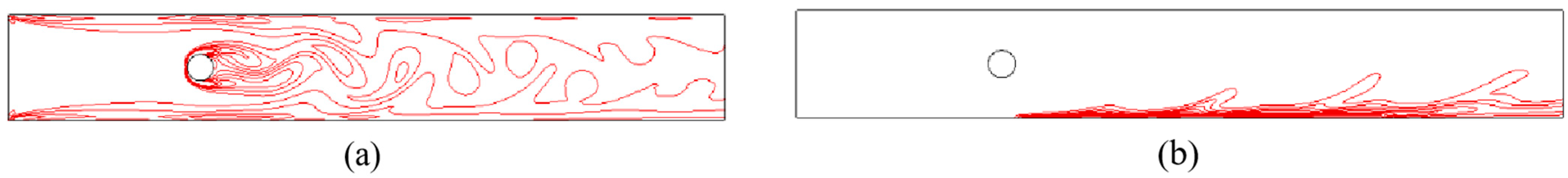
Figure 3.
Time-averaged, local Nusselt number.

Figure 4.
Computational grid (a) XY plane and (b) XZ plane.

Figure 5.
Local Nusselt numbers at different injection ratios: (a,b) , (c,d) and (e,f) .

Figure 6.
Local Nusselt numbers at different injection ratios (X = 1, (a) , (b) and (c) ).

Figure 7.
Thermal efficiency of different injection ratios at various Reynolds numbers.

Figure 8.
Vorticity contours of different injection ratios at : (a) ; (b) .

Figure 9.
Three-dimensional vortex structure corresponding to different injection ratios at : (a) I = 0; (b) I = 1.5; (c) I = 2; (d) I = 2.5; (e) I = 3.
Figure 9.
Three-dimensional vortex structure corresponding to different injection ratios at : (a) I = 0; (b) I = 1.5; (c) I = 2; (d) I = 2.5; (e) I = 3.

Figure 10.
Temperature contours of corresponding to different injection ratios at Z = 0.75 for : (a) I = 1; (b) I = 1.5; (c) I = 2.5; (d) I = 3.
Figure 10.
Temperature contours of corresponding to different injection ratios at Z = 0.75 for : (a) I = 1; (b) I = 1.5; (c) I = 2.5; (d) I = 3.

Figure 11.
Temperature contours of vertical planes at various Reynolds numbers: (a) Re = 100, and Y = 0.8; (b) Re = 200, and Y = 0.8; (c) Re = 300, and Y = 0; (d) Re = 300, and Y = 0.8.
Figure 11.
Temperature contours of vertical planes at various Reynolds numbers: (a) Re = 100, and Y = 0.8; (b) Re = 200, and Y = 0.8; (c) Re = 300, and Y = 0; (d) Re = 300, and Y = 0.8.
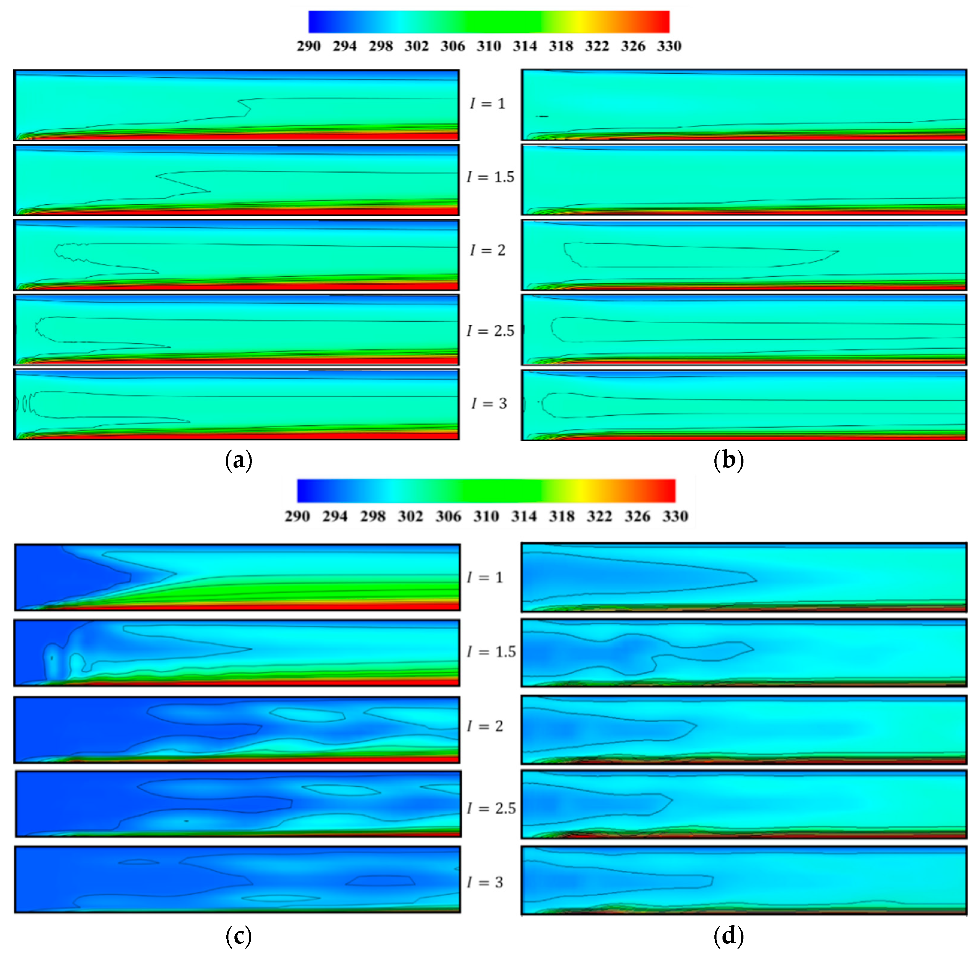
Figure 12.
Thermal efficiency at different angles.

Figure 13.
Thermal efficiency for different jet angles at various Reynolds numbers.

Figure 14.
Local Nusselt numbers of different jet angles at (a) Y = 0; (b) Y = 1.5; (c) X = 1; (d) X = 15.
Figure 14.
Local Nusselt numbers of different jet angles at (a) Y = 0; (b) Y = 1.5; (c) X = 1; (d) X = 15.

Figure 15.
Vorticity contours for of different jet angles at and ().

Figure 16.
Vorticity contours corresponding to clockwise and anticlockwise jet angles at (): (a) anticlockwise; (b) clockwise.
Figure 16.
Vorticity contours corresponding to clockwise and anticlockwise jet angles at (): (a) anticlockwise; (b) clockwise.
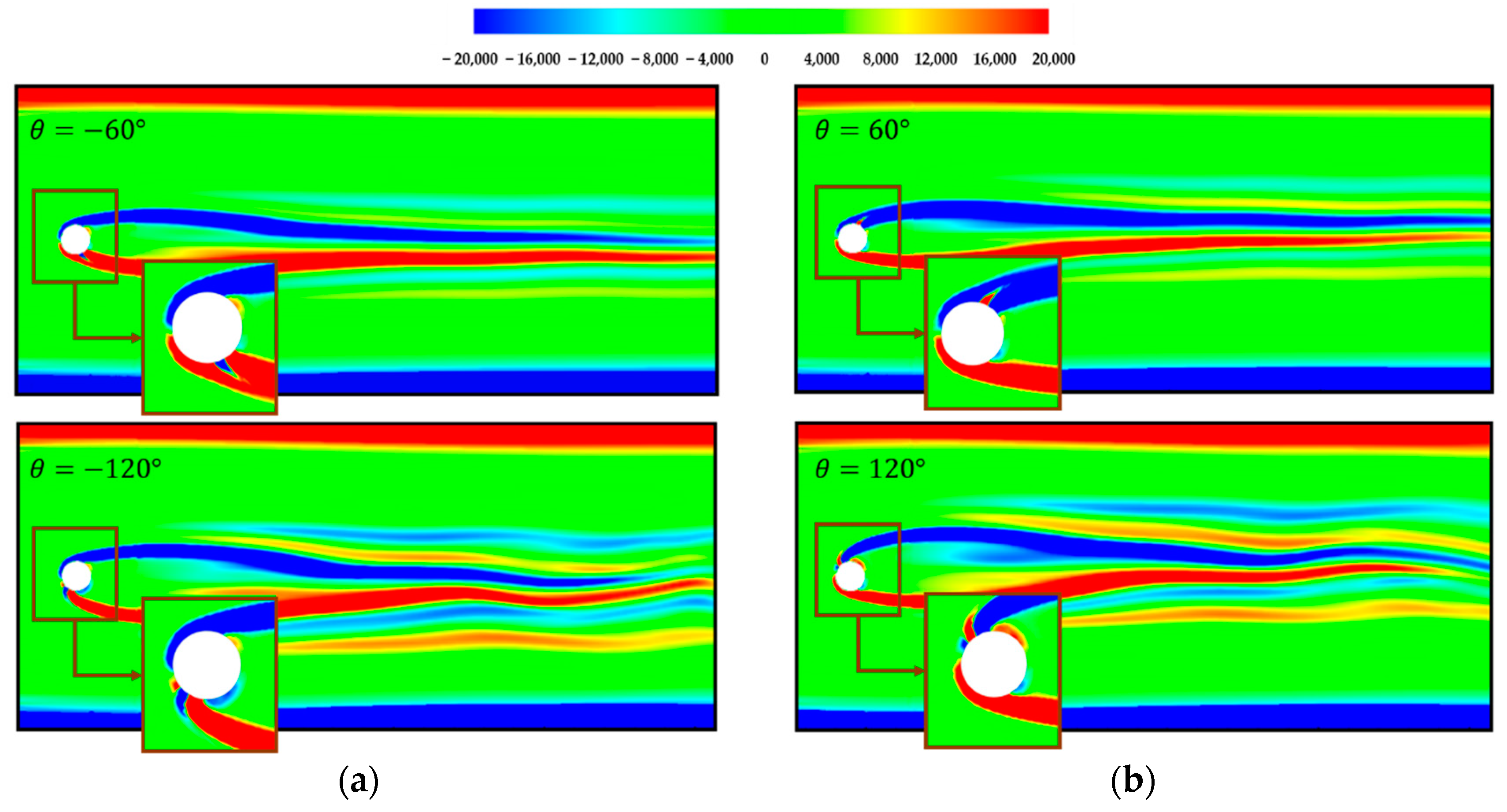
Figure 17.
Vorticity contours for different jet angles at : (a) ; (b) .

Figure 18.
Three-dimensional vortex structure of : (a) ; (b) ; (c) ; (d) .

Figure 19.
Temperature contours of different jet angles at (Y = 1.5).


Table 1.
Grid independence test.
| Grid Size | Coarse | Medium | Fine |
|---|---|---|---|
| Number of nodes Nusselt number (Nu) | 204,732 | 430,170 | 783,496 |
| 3.85 | 3.93 | 3.93 |
Table 2.
Percentage change in thermal efficiency for different jet angles relative to 180°.
| Jet Angles | Thermal Efficiency | Percentage |
|---|---|---|
| 90 | 1.306 | 20.8 |
| 105 | 1.335 | 23.5 |
| 120 | 1.227 | 13.5 |
| 135 | 1.157 | 7.0 |
| 150 | 1.184 | 9.5 |
| 165 | 1.124 | 4.0 |
| 180 | 1.081 | - |
Publisher’s Note: MDPI stays neutral with regard to jurisdictional claims in published maps and institutional affiliations. |
© 2022 by the authors. Licensee MDPI, Basel, Switzerland. This article is an open access article distributed under the terms and conditions of the Creative Commons Attribution (CC BY) license (https://creativecommons.org/licenses/by/4.0/).
Share and Cite
MDPI and ACS Style
Xin, Z.; Kong, X.; Chen, J. Enhancement of Heat Transfer in a Microchannel via Passive and Active Control of a Jet Issued from the Circular Cylinder. Energies 2022, 15, 8287. https://doi.org/10.3390/en15218287
AMA Style
Xin Z, Kong X, Chen J. Enhancement of Heat Transfer in a Microchannel via Passive and Active Control of a Jet Issued from the Circular Cylinder. Energies. 2022; 15(21):8287. https://doi.org/10.3390/en15218287
Chicago/Turabian StyleXin, Zhiqiang, Xiangyu Kong, and Jing Chen. 2022. "Enhancement of Heat Transfer in a Microchannel via Passive and Active Control of a Jet Issued from the Circular Cylinder" Energies 15, no. 21: 8287. https://doi.org/10.3390/en15218287
Note that from the first issue of 2016, this journal uses article numbers instead of page numbers. See further details here.