
Use of Recycled Plastic Fibers to Control Shrinkage and Desiccation Cracking in Clayey Soils

1
Instituto de Ingeniería, Universidad Nacional Autónoma de México, México City 04510, Mexico
2
Facultad de Ingeniería, Universidad Nacional de Colombia, Bogotá 111321, Colombia
*
Author to whom correspondence should be addressed.
Sustainability 2024, 16(9), 3853; https://doi.org/10.3390/su16093853
Submission received: 6 March 2024
/
Revised: 13 April 2024
/
Accepted: 30 April 2024
/
Published: 4 May 2024
Abstract
:Two main issues are addressed in this work. The first issue is environmental concerns about managing plastic waste on a large scale by promoting reuse with low energy requirements in the recycling processes. The second issue is the desiccation cracks in fine soils, induced by prolonged droughts, which have motivated the interest in mitigating the adverse effects on the stability of geotechnical works using recycled materials. Therefore, this work addresses a strategy based on the use of recycled polyethylene terephthalate (PET) and polypropylene (PP) fibers for the reinforcement of soils prone to cracking. To evaluate the effectiveness of plastic fibers in controlling soil volumetric changes and cracking during drying, several experiments were conducted in an environmental chamber to properly simulate and monitor the desiccation process. Image analysis and suction measurements provided several metrics and parameters, and their usefulness is discussed in detail, both for the unconventional determination of the optimum fiber content by weight with 100% effectiveness in preventing cracking and for correlating fiber content with reductions in shrinkage and cracking patterns, thus contributing to the understanding of the behavior of fiber-reinforced soils. Finally, examples of large-scale applications of recycled plastic fibers in geotechnical works are proposed, and the positive environmental impact is estimated.
1. Introduction
One of the most significant consequences of global warming is the progressive desiccation of soils, resulting in volumetric changes that cause deformations due to shrinkage and local or regional cracking. The adverse effects of drying cracks on the mechanical properties, stability, and structure of the soil, as well as the dynamics of surface runoff, groundwater recharge, infiltration, and permeability, have been investigated in several studies [1,2,3]. These changes result in issues such as differential settlement, a reduced soil-bearing capacity, landslides, erosion, and infiltration into water reservoirs or waste deposits [4,5]. While traditional methods of reducing the cracking potential of soils using chemical agents such as lime and Portland cement are well documented, recent efforts in line with the Sustainable Development Goals (SDGs) [6], based on the use of recycled waste for soil strengthening, are in their early stages.
This work proposes the use of recycled fibers from polyethylene terephthalate (PET) and polypropylene (PP), the two most widely produced plastics in the world, as reinforcement for soils prone to cracking due to desiccation. Two critical issues are therefore addressed here: managing the life cycle of plastic waste and mitigating the problems caused by increasing and prolonged droughts [7,8].
This research aimed to improve our understanding of the behavior of fine-grained soils when reinforced with plastic fibers by applying unconventional analyses. Consequently, the main objectives were to quantify the impact of different plastic fiber contents in mitigating cracking and shrinkage during soil desiccation and to determine the optimum fiber content through image analysis. Since this content is usually estimated based on the highest dry unit weight that provides high strength, the use of non-conventional procedures based in imaging helps in determining the optimal fiber content with maximum effectiveness in mitigating cracking and shrinkage, which is a key point in soils prone to cracking during drying. Furthermore, given the conflicting ideas found in the literature [9,10], suction measurements were performed to verify whether the inclusion of fibers in the soil modifies the retention curve.
For these purposes, a comprehensive experimental study was conducted using low-plasticity clayey samples with different PET and PP fiber contents. These samples were subjected to controlled desiccation in an instrumented environmental chamber to monitor changes in water content, soil suction, and the cracking process through digital image capture. A detailed image analysis was conducted to study the morphology and geometry of cracks and shrinkage, revealing specific metrics and parameters that govern the changes and patterns observed as a function of time, fiber content, moisture reduction, and soil suction. Finally, two specific practical applications of reinforced soils in geotechnical engineering are proposed, and the benefits of using recycled plastic fibers are estimated based on the results of this study.
2. Fundamentals and Background
This section presents the basics and relevant background on soil desiccation cracking, the quantification of soil cracking using image analysis, suction in fiber-reinforced soils, and the environmental benefits of recycled plastic fibers for soil stabilization.
2.1. Desiccation Cracking of Soils
During desiccation, the water content of the soil decreases, resulting in a reduction in volume. Simultaneously, tensile stress increases and soil strength may be exceeded, causing cracking until no further volume change occurs [11,12]. These cracks propagate and interconnect over time to form a network of geometric block patterns, as shown in Figure 1.
The susceptibility of fine soils to cracking under varying environmental conditions is significantly influenced by mineralogy [13] and particle rearrangement during drying [14]. Variables such as the geometric properties of cracks and shrinkage patterns have provided a practical way to characterize the soil and the relationship with mechanical behavior [15,16,17]. Additional parameters from fracture mechanics [18,19], the tensile strength [20], and the soil retention curve [21,22] have also been used for various types of soil crack characterizations.
Lloret and Olivella [23] dried clay samples in circular molds 4–16 mm thick and observed three important things: (a) sample thickness has no effect on vertical deformation at crack initiation; (b) the time to crack initiation is linearly related to the sample volume; and (c) the greater the thickness, the greater the crack separation. Another study has shown that cracking starts at the same water content, even though the initial water content is different [24]. Furthermore, a quantitative analysis suggests that there is a minimum aspect ratio of 5.8 below which the material does not undergo macroscopic cracking [25].
In addition, the effects of mold geometry, initial test conditions, and the drying rate on crack initiation and progression on reconstituted clays have been studied; the obtained ratio of crack area to total area at a given time varied from 0.2 to 11.2. [26].
In summary, comprehensive analyses of soil cracking should consider a wide variety of aspects: microstructural changes, micromechanical analyses of the evaporation process, changes in the pore water pressure, water dynamics throughout the soil, the effects of soil shrinkage and tensile strength, and the formulation of models for predicting crack characteristics such as the width, depth, and variability of the geometry during propagation [27].
2.2. Quantification of Soil Cracking
Since crack morphology has inspired many studies, the image analysis technique has been crucial in monitoring the cracking process of soils in laboratory experiments using tools based on X-ray tomographic images [28] and photographic images [29,30,31,32,33], and several indices have been proposed based on the measurements. For example, the crack intensity factor (CIF) is defined as the ratio of the crack area to the initial area [15]. CIFtot can be quantified as the ratio of the crack and shrinkage areas to the initial area [34]; this factor is also known as the crack density factor (CDF) [35]. Alternatively, CIF* is the ratio of the crack area to the reduced area after shrinkage is complete [36].
These factors have been quantified in various studies to characterize the cracking along with other geometric parameters, such as the crack length (CL) and crack width (CW) [37]. In compacted fine soil samples with an exposed area of 5 cm × 5.5 cm, crack patterns were fully developed in the different samples after 50 h, and the more compacted samples showed more complex patterns with the CL varying between 11 cm and 14 cm and the CW between 0.6 mm and 0.8 mm [38].
Many studies in the literature have analyzed crack formation through bidimensional (2D) studies due to challenges in measuring and quantifying cracking parameters in three dimensions (3D). Representing soil in a 2D plane allows for a clear visualization of cracking patterns and their distribution. In a notable effort, Tang et al. [39,40] explored crack propagation and volume changes in compacted clay samples during desiccation using X-ray Computed Tomography (CT). Besides 3D volumetric investigations, CT scans hold potential for characterizing spatial variations in soil properties. However, the performance of CT may face challenges from poor-quality images, impacting accurate predictions of object composition. Considerations such as beam hardening and partial volume are crucial for ensuring image accuracy. Although higher X-ray intensity or micro-focus X-ray tubes can enhance quality, their applicability to larger-scale characterizations is constrained by resolution limitations. Therefore, efforts should be continued to achieve a more accurate 3D analysis.
2.3. Soil Reinforcement with Plastic Fibers
In an effort to more effectively mitigate the impact of plastic waste on the environment, several studies have reported on the use of recycled plastic in construction materials [41]. The use of recycled plastics has been studied as a reinforcing material for large-scale engineering projects, such as embankments, reservoir, and landfill linings [42,43], and to improve unstable fine-grained soils [44,45].
Synthetic fibers from polyester [46,47] and polypropylene [48,49,50,51] have been tested, and optimal fiber content between 0.3% and 1% by weight have been found to improve physical and mechanical properties of soils. The mixing and compaction processes are found to be highly relevant as flocculation and segregation can occur depending on the technique used.
Most of the aforementioned studies have focused on the evaluation of the mechanical properties of fiber-reinforced soil. Therefore, it is necessary to perform detailed analyses of the incidence of fiber inclusion on both the morphology of the crack and the shrinkage of the reinforced soil.
2.4. Suction in Reinforced Fiber Soil
Soil desiccation is a complex, coupled, multiphysical process involving water evaporation, volume contraction, and cracking as suction and effective stress within the soil increase. Desiccation cracking initiates and propagates due to internal stress accumulation; therefore, the intensity and characteristics of cracking will also depend on the relationship between the suction and soil water content.
When fibers are incorporated into the soil, the composition and physical arrangement of particles are altered, and the volumetric relationships change. These changes could affect the soil retention curve and the suction value because they depend on the capillary and adhesive forces acting in both the pores and the particle surfaces.
It is worth mentioning that few studies have been found in the literature related to obtaining the retention curve of fiber-reinforced soil, and their results have not been conclusive. On the one hand, water retention curves obtained with a porous plate apparatus on compacted clays reinforced with polypropylene and nylon fibers with contents between 0.3% and 0.5% have shown that the fibers did not have a significant influence on the volumetric water content of the treated soils [9]. On the other hand, in similar experiments but using the filter paper method, a significant increase in the Air Entry Value (AEV) was observed with increasing polypropylene fiber content. This increment would be related to the reduction in porosity and a greater suction requirement to desaturate the reinforced soil [10].
2.5. The Environmental Benefits of Plastic Reuse
According to the Organization for Economic Cooperation and Development (OECD), more than 350 million tons of plastic waste were generated in 2019 [52]; it was also estimated that 49% was disposed of in landfills and 22% in the environment, while 19% was incinerated, and only 10% was recycled. The poor management of plastic waste induces risks such as flooding due to the clogging of drainage systems, the shortening of the useful life of landfills, the contamination of groundwater by leachate from incineration ashes, and toxic and greenhouse gas emissions [53].
Since the energy required to recycle plastics is much less than the energy required to produce them, reuse on a larger scale is promoted as a circular economy strategy for plastic waste management [54]. Mechanical treatment, such as that used in plastic fiber production, is recommended over chemical or thermal treatments because it is simpler, less polluting, and more energy efficient. It is estimated that 1 kg of bottles can produce 900 g of fiber. Different applications in terms of the number of bottles to reuse could be estimated based on the average weight of some PET bottles: 6.4 g for 250 mL, 18.7 g for 600 mL, and 32.6 g for 1500 mL [55].
The benefits of recycling in terms of reducing the carbon footprint can be estimated using the model proposed by Dormer et al. [56], who found that the production of 1 kg of plastic product generates 3.5 kg of CO2e, while the use of recycled PET reduces the carbon footprint to one third. It has also been estimated that producing 1 kg of recycled PET short fiber emits 0.3 kg of CO2e [57]. In contrast, the incineration of 1 kg of PET produces 1.38 kg of greenhouse gas (GHG) emissions, and landfilling, 0.99 kg of GHG [58]. This means that recycling PET can reduce greenhouse gas emissions by 75% compared to incineration and by 65% compared to landfilling.
3. Materials and Methods
This section describes the materials and the procedures used for preparing soil–fiber mixtures, drying samples in an environmental chamber, analyzing images, and measuring parameters of interest. To evaluate both quantitative and qualitative parameters related to desiccation cracking in samples of fine soil mixed with synthetic fibers, an experimental laboratory program was conducted, including sample preparation, testing, and analysis, as shown in the flowchart in Figure 2.
3.1. Characteristics of the Recycled Plastic Fibers
3.2. Soil Characteristics
The clayey soil samples used in this study were obtained from a 4 m deep excavation carried out at the Scientific and Technical Unit of Agrópolis, in the Llobregat Delta region of Catalonia, Spain. This soil has been characterized in previous studies [60,61], and its main properties are presented in Table 2.
3.3. Sample Preparation
For shrinkage crack formation in all test samples, water content above the liquid limit of the soil is necessary. So, 30% water content was added to the disaggregated air-dried soil, and it was mixed by hand with a spatula. The soil was stored for 24 h in a room with controlled humidity and temperature conditions to ensure homogeneity. Soil moisture was measured before and after storage.
Since this study was focused on evaluating the effect of varying fiber content on cracking and shrinkage patterns, the soil was divided into portions, and the predetermined percentages of plastic fibers were manually incorporated into each portion and then mixed with a spatula to avoid clumping (see Figure 4); visual inspection was performed to assess the randomness of the fibers throughout the soil. Based on previous research [68], the following fiber content values were selected: 0.005%, 0.02%, 0.1%, and 0.5% for PET fibers and 0.1%, 0.3%, and 0.5% for PP fibers. Higher fiber content makes mixing with soil difficult. As a baseline reference, samples without fibers were also prepared.
Following the methodology proposed by Colina and Roux [25] regarding the minimum aspect ratio of specimens to induce cracks while minimizing scale effects, samples 2 cm thick and 28 cm long were prepared with an initial surface area of 504 cm2 (Ai).
3.4. Desiccation in the Environmental Chamber and Suction Measurement
The experiment for this study was conducted in a 1.0 m × 1.0 m × 1.5 m acrylic environmental chamber equipped with the following devices (Figure 5): air inlet and outlet ducts connected to a humidifier and dehumidifier; sensors to measure the temperature and relative humidity; scales for material weight control; an Olympus C-5050Z digital camera manufactured by OM System, Spain, to obtain images during desiccation; and a data acquisition system. The equipment was developed at the Universitat Politècnica de Catalunya (UPC) and described in detail by Lakshmikantha et al. [69].
The environmental chamber creates a dry atmosphere by lowering the relative humidity around samples using a dehumidifier that removes humid air from one side of the chamber and introduces dry air through the other side. The air is constantly in circulation at the same temperature, so there is no heat loss during the process. During testing, the average temperature (T) inside the chamber was 22 °C, and the average relative humidity (RH) was 30% (see Table 3).
Each sample was placed in the environmental chamber, and parameters such as their weight, the relative humidity, and chamber and soil temperatures were recorded throughout the drying process. Photographs were taken every hour to systematically monitor the effect of the gradual loss of water content on the samples.
During the PP fiber-reinforced soil drying, a complementary suction measurement analysis was performed combining a tensiometer (up to 100 kPa) and dew point hygrometer WP4C soil water potential instrument measurements (below 100 kPa) (Figure 6).
3.5. Image Analysis
Qualitative and quantitative analyses of the crack and shrinkage morphology were performed using ImageJ software version 1.53c. Image processing included the following steps, as illustrated in Figure 7: initial preparation, thresholding, scaling, and measurements.
The initial preparation phase was conducted to convert each original color image to an 8-bit grayscale image. This was essential for image segmentation to separate the cracks from the rest of the area while facilitating image edge detection. To address potential shadows from uneven illumination, two simple methods were used to distinguish cracks from unfractured areas: (a) eliminating smooth backgrounds and (b) applying a blur filter to improve edge definition by subtracting a smoothed version from the original image.
The second step was to convert the grayscale image to a black and white image using binary procedures to separate the cracked and non-cracked cells. Generally, an object pixel is assigned a value of “1”, whereas a background pixel is assigned a value of “0”. The individual pixels in a grayscale image are marked as “object” pixels if their value is within the threshold range (considering that an object is brighter than the background). If not, they are marked as “background” pixels.
Finally, the crack and shrinkage metrics selected for this study were measured, and qualitative and quantitative analyses were performed using the scaled images; the metrics analyzed included the crack length (CL), initial area (Ai), shrinkage area (As), reduced area (Ar), and cracked area (Ac) (see Figure 8). Based on these metrics, the indices defined in Table 4 were calculated. For this work, it was proposed to calculate the average crack width (CWaw), as indicated in the same table.
4. Results and Discussion
4.1. Conditions of Induced Desiccation
Figure 9 shows the environmental conditions during desiccation for the soil sample with 0.1% fiber. Soil temperatures (T soil) were slightly higher (1 to 1.5 °C) than those in the chamber (T chamber), due to heat transfer from the air in the chamber to the soil. The average temperatures for the other samples ranged from 20 to 23 °C in the chamber and from 21 to 24 °C in the soil. As specified in the experimental design, the relative humidity (RH) was maintained at 30%.
Figure 10 shows the loss of water over time as a function of the amount and type of fiber in the soil. Two stages were identified during the evaporation process: in the first one, there is a constant rate of water loss up to about 5% water content in the soil. The inflection point occurs after 60 to 70 h of drying, and a second stage begins with a residual nonlinear decay of the water loss rate. Volumetric and cracking changes in the samples were observed during the first stage.
The sample with 0.005% PET fiber dried even faster than the unreinforced soil, while the soil with 0.5% PET fiber showed the slowest drying process. This is a great advantage because the slower the drying process, the less likely that cracking will occur.
4.2. Visual Assessment during Desiccation: Qualitative Analysis
By monitoring the samples in the environmental chamber, it was possible to observe the progression of cracking as a function of time, suction, water loss, and fiber content. Figure 11, Figure 12 and Figure 13 show the effect of the addition of recycled PET and PP fibers in controlling crack initiation and propagation in the soil samples, compared to unreinforced soil.
Through representing the soil in a 2D plane, it was possible to visualize the crack patterns and their distribution, facilitating the identification of the key parameters defined in this study for crack and shrinkage characterization. In addition, the aspect ratio of the specimens used in this work to induce cracking while minimizing scale effects involved very small thicknesses compared to the surface area of the specimens, which helped reduce the dimensionality of the analyses from 3D to 2D.
The volumetric shrinkage process can be seen along the edges formed at the interface between the specimens and the molds. Shrinkage progressed over time and was most pronounced in samples with 0.1% or less fiber content. This phenomenon suggests that the influence of edge conditions on the shrinkage of low-fiber-content samples should be considered in future studies.
The unreinforced soil showed crack initiation after 16 h when it had only 6% water loss. In contrast, soil mixtures with PET fibers, even in the samples with the lowest fiber addition (0.005%), managed to effectively prevent crack formation during the same drying period.
Another qualitative feature relates to the crack patterns and networks observed in the samples with some degree of cracking (0.005% and 0.01% PET fiber and 0.1% PP fiber), which showed small cracks at the corners and the formation of two rectangular polygons. Since the unreinforced soil exhibited a complex, interconnected crack network containing 12 irregular polygons, it can be concluded that even at the lowest percentages of fibers, an efficiency of 83% was achieved in limiting crack interconnection and block formation. The morphology of the crack patterns developed in the low-fiber-content specimens suggests that the behavior may be conditioned by the width-to-length ratio of the specimens; this issue requires more in-depth research on the effects of edges.
The greatest effectiveness in preventing cracks in the soil was observed in samples with 0.1% and 0.5% PET and 0.3% and 0.5% PP fiber content, as no cracks were observed during the entire drying process. However, the greatest benefit in simultaneous shrinkage control was achieved with 0.5% PET and 0.3% PP fiber. The difference in the optimum fiber content may be due to the sizes of the fibers and their scaling effects. It should be noted that the fibers maintained contact with the soil throughout the drying process and did not fail, i.e., the tensile strength of the fibers was not exceeded, regardless of their size.
4.3. Effect of Plastic Fibers on the Quantitative Parameters of Soil Cracking and Shrinkage
Based on the procedure described in Section 3.5, the parameters defined in Figure 8 were measured, and the indices listed in Table 4 were calculated for all samples.
For the unreinforced soil, the crack network reached a total length of 100 cm between 24 and 72 h. Although progress stopped at this point, a slight increase in the crack opening was observed, reaching 0.5 cm by the end of the experiment. These results are closely related to those obtained by Lakshmikantha et al. [37], who obtained CL values of 112.5 cm and CWav values of 0.7 cm on samples with a 625 cm2 surface area and 2 cm thickness.
Alternatively, the ratio of lengths to widths obtained in this study was approximately 7 to 1 compared to those reported by Colombi et al. [38] for compacted fine-grained soils, which contrasts considerably with the surface ratio of 28 to 1 between the samples of both studies (500 vs. 18 cm2). These values demonstrate the combined effects of the sample size and degree of compaction of the soils. In this sense, our study offers certain advantages, since it is expected that the larger the observation area, the greater the representativeness of the observed phenomena and the smaller the scale effect.
Another relevant issue in unreinforced soil is the increase in the drying rate between 48 and 72 h, which is the period over which cracks are developed. Certainly, crack walls were exposed to the chamber environment, increasing the area exposed to drying, resulting in greater water loss. This finding also contrasts with those of Cuadrado et al. [60], who argued that cracking does not change clay evaporation rates.
As for the reinforced soil samples, the metrics obtained to quantify the effects of plastic fibers are highly consistent with visual observations in terms of 100% crack prevention efficiency for 0.1% and 0.5% PET and 0.3% and 0.5% PP fiber content, by weight.
Figure 14 shows the progression of the crack length (CL) over the drying period and its relationship with the average crack width (CWav). Even with the addition of just 0.005% or 0.02% PET fiber, the benefits of preventing cracking in fine-grained soils are evident: crack initiation is delayed, and the total crack length decreases from 100 cm (unreinforced soil) to less than 29 cm (reinforced soil), while the average width decreases to less than 0.3 cm. This indicates an efficiency of up to 70% at decreasing crack progression and 46–72% at reducing crack opening. The crack control efficiency was 100% for the samples not shown in the graph.
Regarding the areas calculated from the images, marked decreases are evident in the shrinkage area (As) and crack area (Ac) as the fiber content increases, as shown in Figure 15. In unreinforced soil, the shrinkage and crack area were 59 cm2, whereas at a fiber content of 0.5%, these areas were reduced to 27 cm2 (55%) with PET fibers and to 22 cm2 (63%) with PP fibers.
Although the effect of the fibers on limiting the cracked area (Ac) during desiccation is evident, the response of the reinforced material is very interesting as it shows higher shrinkage areas (As) at the edges than in the unreinforced soil. This behavior can be explained by the development of higher internal tensile strengths due to the fiber–soil interaction compared to those generated at the material–mold interface.
Regarding the metrics that relate the cracked areas to the surface of the specimens, it is important to note that no significant difference was observed between the CIF and CIF* parameters, which varied between 0% and 2% for reinforced soil, with maximum values close to 8% for unreinforced samples, demonstrating the success of PET fibers in limiting soil cracking.
Since the measured crack areas are very small, the CIFtot index provides a valuable approach by combining the shrinkage area of the samples with the crack area. As illustrated in Figure 16 and Figure 17, the CIFtot decreases as the fiber content increases: from 11.8% in unreinforced soils to 5.5% in PET-reinforced soil, and to 4.5% with PP inclusion; again, the greatest benefit in surface integrity was obtained with 0.5% fiber. It can also be observed that the reinforcement allowed the soil to withstand higher levels of desiccation before shrinkage and cracking occurred.
As further validation, we found that the CIFtot value obtained for the unreinforced soil (11.8%) was very close to the 12.7% obtained by Lakshmikantha et al. [33] for 625 cm2 samples of the same soil.
An integral analysis of the results obtained indicates that the addition of recycled plastic fibers to the studied soil considerably influences the cracking patterns in terms of length, opening, crack area, propagation speed, and connectivity to form networks. In general, these parameters improved with increasing fiber content, showing high efficiency in reducing desiccation cracking and shrinkage, especially at 0.5% PET and PP fiber contents by weight.
4.4. Effect of Plastic Fibers on the Soil Retention Curve
One of the most characteristic phenomena of the behavior of unsaturated soil is related to the volumetric deformations when the degree of saturation (Gw) changes. These volumetric deformations are also related to the increase or decrease in soil suction.
Since incorporating fibers could promote changes in both the void ratio and the suction values of the fiber-reinforced soil, suction measurements were performed with tensiometers and WP4C devices for soil–PP fiber samples. The combination of the two methods used to measure suction provided reasonably continuous and consistent retention curves as shown in Figure 18.
It can be observed that the differences in the suction curves of natural soil and soil reinforced with different concentrations of PP fibers are not significant. This behavior is consistent with that observed by Puppala et al. [9] for soils reinforced with similar fibers. Although we cannot rule out the possibility that synthetic fibers have a slight effect on soil suction, this variation does not appear to have a significant effect on the cracking behavior of the soil under the conditions studied here.
The fact that the soil retention curve remains unchanged with the addition of fibers to the soil simplifies the correlation between variables governing cracking in fine soils reinforced with plastic fibers. Furthermore, the initiation of cracking in samples with fibers occurs under the same conditions of water content and suction as those without fibers. This also could imply that there is no significant variation in the hydraulic parameters of the soil with synthetic fibers, but further studies should be carried out to verify this.
4.5. Environmental Benefits and Considerations for Recycled Plastic Fiber Soil Reinforcement
The potential for the practical application of recycled plastic fibers in geotechnical engineering projects involving soils susceptible to cracking was finally assessed in this study, thereby expanding both the usable volume on a large scale and the impact on the mitigation of the effects of plastic waste on the environment.
Considering that the optimal content of plastic fiber to be added to the soil is 0.5% by weight and that the dry unit weight of the tested soil is 17.8 KN/m3, it is estimated that 8.9 kg of fiber would be required to reinforce 1 m3 of soil. To produce this amount of fiber, 9.9 kg of bottles would be recycled, as 1 kg of bottles is needed to produce 0.9 kg of fiber.
In addition, two examples of geotechnical applications of soil fiber reinforcement are presented here to provide a quantitative idea of the benefits of plastic recycling. The demand for fiber and its environmental benefits increases with the thickness of the soil and the area to be reinforced. The examples are as follows:
(a) Roadway subgrade reinforcement: It is estimated that 14.2 tons of plastic fiber would be required to improve the tensile response of a 0.2 m thick subgrade layer for an 8 m wide, 1 km long road.
(b) Slope erosion control: for a slope that is 10 m high and 100 m long, assuming a thickness of 0.2 m of soil to be reinforced, 1.8 tons of PET fiber would be required.
Furthermore, the benefits of recycling plastics for fiber production are significant in reducing the carbon footprint compared to other methods of managing plastic waste. For example, the plastic needed to make the 14.2 tons of fiber to reinforce 1 km of road subgrade would emit 4.8 tons of CO2e in fiber production, 22 tons if incinerated, and 15.8 tons if landfilled.
As large-scale application is achieved, the benefits of recycling PET and PP bottles into fibers will become more significant in both plastic waste management and problematic soil control for engineering applications.
Finally, the use of recycled plastic fibers for soil reinforcement and solving the geotechnical problem as addressed in this work is in line with three of the Sustainable Development Goals (SDGs):
- (i)
- Goal 9 seeks to build resilient infrastructure, promote sustainable industrialization and innovative designs for durable solutions, and develop more efficient recycling methods and material specifications.
- (ii)
- Goal 12 is to ensure sustainable consumption and production. Reusing plastic reduces the need for new raw materials in both soil stabilization and plastic manufacturing, helping to conserve non-renewable natural resources (target 12.2). Additionally, target 12.5 aims to significantly reduce waste generation through the prevention, reduction, recycling, and reuse of materials and products. Hence, recycling plastics to produce fibers reduces solid waste and pollutants by diverting them from landfills or incinerators.
- (iii)
- Goal 13 is to take action to combat climate change and its impacts. Soil reinforcement with recycled plastic fibers strengthens the ability to adapt to drought-related hazards and their effects on infrastructure.
5. Conclusions
The result of this study is a strategy to address two aspects of current interest: the mitigation of problems generated by soils susceptible to cracking due to intense and prolonged droughts and the management of the life cycle of plastic waste.
5.1. Effectiveness of Recycled Plastic Fibers in the Reduction of Soil Cracking and Shrinkage
It can be observed that the fibers significantly limit desiccation cracking in the soil-fiber system. This effect was most pronounced at 0.1% and 0.5% for PET fiber and 0.3% and 0.5% for PP fiber, as no cracks developed during the observation period, showing 100% effectiveness in preventing cracking.
Regarding the crack patterns and networks observed, it can be concluded that even at the lowest percentages of fibers, an efficiency of 83% was achieved in limiting crack interconnection and block formation. The morphology of the crack patterns developed in the low fiber content specimens suggests that the behavior may be conditioned by the width-to-length ratio of the specimens.
In relation to the volumetric change due to lateral shrinkage of the specimens (As), the progression over time was more evident in reinforced samples, especially at low fiber contents, than in the unreinforced soil, apparently due to the development of higher internal tensile stresses from fiber–soil interactions than those generated at the material–mold interface.
The following comments can be drawn from the integral analysis of the metrics studied. (a) The CIFtot index was the most valuable metric for evaluating the effect of soil fiber reinforcement because it combines the shrinkage area with the crack area of the specimens. (b) No significant difference was observed between the CIF and CIF* parameters. (c) The Ac and CL are very relevant to the extent that the cracking is higher; in addition, they allow the estimation of the CWav.
Based on the integral analysis for all samples, we can conclude that the best overall performance in terms of limiting both cracking and shrinkage is achieved with 0.5% recycled PET and PP fiber content by weight. Therefore, the methodological strategy employed in this study, based on imaging, allowed for the determination of the optimal amount of recycled plastic fibers to effectively inhibit cracking in fine-grained soils.
Notably, the software tools for the analysis of the digital images of the soil–fiber specimens were successfully applied in this study. Their use allowed the identification of qualitative morphological features and the quantification of geometric parameters of the cracks as a function of time, fiber content, and the water loss in the soil–fiber system.
5.2. Suction Behavior of Reinforced Soil
During the desiccation tests, an important parameter was evaluated: the determination of the water retention curve of PP fiber-reinforced soils to evaluate the effect of fibers on the suction properties. The results obtained show that, although synthetic fibers appear to have a slight effect on soil suction, this variation does not appear to have a significant effect on the cracking behavior of the soil under the conditions studied here.
5.3. Environmental Benefits
Considering that the disposal of plastic waste generates greenhouse gases that contribute to global warming which, in turn, accelerates soil desiccation, the reuse of plastic containers is a way of compensating and positively impacting the fight against climate change to achieve net zero by 2050.
We found that 8.9 kg of plastic fiber would be needed to reinforce 1 m3 of the clay soil studied, which would require the recycling of 9.9 kg of bottles. For the two geotechnical applications proposed, we estimated that to reinforce 1000 m2 of slope and 8000 m2 of road subgrade, 1.8 tons and 14.2 tons of fibers, respectively, would be required (assuming 0.2 m. thickness). To produce the last amount of fiber, 4.8 tons of CO2e would be emitted in the fiber production process, while incineration would emit 22 tons of CO2e, and landfilling, 15.8 tons. Therefore, the reduction in carbon footprint is also significant compared to other methods of managing plastic waste. The environmental benefits in terms of plastic reuse, waste generation, and gas emission reduction would be greater as the area and thickness of the soil increase.
Finally, the study carried out here can be linked to the Sustainable Development Goals, as set out in Section 4.5.
6. Recommendations
Based on our findings and existing research, some areas for improvement and innovation are presented in this section for future research on cracking behavior and volumetric changes in reinforced soils:
- (a)
- The optimum fiber content was determined through image analysis in terms of the maximum efficiency in crack reduction and volumetric changes. It is necessary to complement this with conventional tests to verify that the reinforced soil provides high-density and strength properties.
- (b)
- Investigating soils over a wide range of plasticity indices is important, since soil plasticity is a critical factor in determining the behavior of fine reinforced soils.
- (c)
- We observed that shrinkage progressed with time and was most pronounced in samples with low fiber content. Therefore, the influence of edge conditions on shrinkage should be thoroughly investigated.
- (d)
- In our qualitative evaluation of the samples, fiber size showed some relevance. Therefore, fiber size and the scaling effect should be addressed in more detail.
- (e)
- While 2D imaging provides valuable information and simplifies dimensionality, it does not fully capture the three-dimensional features of soil cracking for more complex analyses, such as pore size and distribution with fiber size, length, and content. Therefore, further efforts should be made to develop more advanced 3D analyses for a more complete representation of fiber-reinforced soil behavior.
- (f)
- The results obtained from the suction measurements suggest that despite the structural change of the soil due to the interaction between the particles and the fibers, there is no appreciable change in the hydraulic parameters of the plastic fiber reinforced soil, but further investigations are needed to confirm this.
- (g)
- We recommend full-scale physical modeling in natural soil exposed to natural environment in instrumented field tests. This extension would allow the inclusion of larger soil fiber masses to study the influence of other parameters on stresses, deformations, and soil cracking: compaction, suction, edge effects, depth, and weather parameters. For these field tests, it is suggested to follow the recommendations on fiber addition, mixing, and compaction methods that have been found to be satisfactory in providing a reasonably random distribution of fibers in other types of soils [45,70,71,72].
- (h)
- Finally, studies should be conducted to evaluate the potential adverse effects of synthetic fibers as soil reinforcement. For example, future investigations of plastic-modified soils should consider testing for water leachability.
Author Contributions
Conceptualization, C.H. and E.B.; methodology, C.H., G.B. and E.B.; software, C.H.; validation, G.B. and E.B.; formal analysis, C.H. and G.B.; investigation, C.H. and G.B.; resources, E.B.; data curation, C.H. and G.B.; writing—original draft preparation, C.H.; writing—review and editing, G.B. and C.H.; visualization, C.H.; supervision, E.B.; project administration, E.B. All authors have read and agreed to the published version of the manuscript.
Funding
This research received no external funding and the APC was funded by Instituto de Ingeniería, Universidad Nacional Autónoma de México.
Institutional Review Board Statement
Not applicable.
Informed Consent Statement
Not applicable.
Data Availability Statement
The raw data supporting the conclusions of this article will be made available by the authors on request.
Conflicts of Interest
The authors declare no conflict of interest.
References
- Feng, S.; Fu, Q. Expansion of global drylands under a warming climate. Atmos. Chem. Phys. 2013, 13, 10081–10094. [Google Scholar] [CrossRef]
- Berg, A.; Findell, K.; Lintner, B.; Giannini, A.; Seneviratne, S.I.; van den Hurk, B.; Lorenz, R.; Pitman, A.; Hagemann, S.; Meier, A.; et al. Land–atmosphere feedback amplify aridity increase over land under global warming. Nat. Clim. Chang. 2016, 6, 869–874. [Google Scholar] [CrossRef]
- Louati, F.; Trabelsi, H.; Jamei, M.; Taibi, S. Impact of wetting-drying cycles and cracks on the permeability of compacted clayey soil. Eur. J. Environ. Civ. Eng. 2018, 25, 696–721. [Google Scholar] [CrossRef]
- Guo, L.; Chen, G.; Ding, L.; Zheng, L.; Gao, J. Numerical simulation of full desiccation process of clayey soils using an extended DDA model with soil suction consideration. Comput. Geotech. 2023, 153, 105107. [Google Scholar] [CrossRef]
- Kandalai, S.; John, N.J.; Patel, A. Effects of Climate Change on Geotechnical Infrastructures—State of the art. Environ. Sci. Pollut. Res. 2023, 30, 16878–16904. [Google Scholar] [CrossRef] [PubMed]
- United Nations. Transforming Our World: The 2030 Agenda for Sustainable Development. 2015. Available online: https://sdgs.un.org/publications/transforming-our-world-2030-agenda-sustainable-development-17981 (accessed on 5 February 2024).
- Tang, C.S.; Zhu, C.; Cheng, Q.; Zeng, H.; Xu, J.J.; Tian, B. Desiccation cracking of soils: A review of investigation approaches, underlying mechanisms, and influencing factors. Earth Sci. Rev. 2021, 216, 103586. [Google Scholar] [CrossRef]
- Zeng, H.; Tang, C.S.; Cheng, Q.; Zhu, C.; Yin, L.Y.; Shi, B. Drought induced soil desiccation cracking behavior with consideration of basal friction and layer thickness. Water Resour. Res. 2020, 567, e2019WR026948. [Google Scholar] [CrossRef]
- Puppala, J.; Musenda, C. Effects of fiber reinforcement on strength and volumen change behavior of expansive soils. In Proceedings of the 79th Annual Meeting, Washington, DC, USA, 9–13 January 2000. [Google Scholar] [CrossRef]
- Malekzadeh, M.; Huriye, B. Hydro-mechanical behavior of polypropylene fiber reinforced expansive soils. KSCE J. Civ. Eng. 2014, 18, 2028–2033. [Google Scholar] [CrossRef]
- Li, J.H.; Zhang, L.M. Study of desiccation crack initiation and development at ground surface. Eng. Geol. 2011, 123, 347–358. [Google Scholar] [CrossRef]
- Sanchez, M.; Atique, A.; Kim, S.; Romero, E.; Zielinski, M. Exploring desiccation cracks in soils using a 2D profile laser device. Acta Geotech. 2013, 8, 583–596. [Google Scholar] [CrossRef]
- Tay, Y.Y.; Stewart, D.I.; Cousens, T.W. Shrinkage and desiccation cracking in bentonite-sand landfill liners. Eng. Geol. 2001, 60, 263–274. [Google Scholar] [CrossRef]
- Tang, C.; Shi, B.; Liu, C.; Zhao, L.; Wang, B. Influencing factors of geometrical structure of surface shrinkage cracks in clayey soils. Eng. Geol. 2008, 101, 204–217. [Google Scholar] [CrossRef]
- Miller, C.J.; Mi, H.; Yesiller, N. Experimental analysis of desiccation crack propagation in clay liners. JAWRA 1998, 34, 677–686. [Google Scholar] [CrossRef]
- Yesiller, N.; Miller, C.J.; Inci, G.; Yaldo, K. Desiccation and cracking behavior of three compacted landfill liner soils. Eng. Geol. 2000, 57, 105–121. [Google Scholar] [CrossRef]
- Prat, P.C.; Ledesma, A.; Lakshmikantha, M.R. Size effect in the cracking of drying soil. In Fracture of Nano and Engineering Materials and Structures; Springer: Berlin/Heidelberg, Germany, 2006; pp. 1373–1374. [Google Scholar]
- Hallet, P.D.; Newson, T.A. Describing soil crack formation using elastic–plastic fracture mechanics. Eur. J. Soil Sci. 2005, 56, 31–38. [Google Scholar] [CrossRef]
- Amarasiri, A.L.; Kodikara, J.K.; Costa, S. Numerical modelling of desiccation cracking. Int. J. Numer. Anal. Methods Geomech. 2011, 35, 82–96. [Google Scholar] [CrossRef]
- Zeng, H.; Tang, C.S.; Cheng, Q.; Inyang, H.I.; Rong, D.Z.; Lin, L.; Shi, B. Coupling effects of interfacial friction and layer thickness on soil desiccation cracking behavior. Eng. Geol. 2019, 260, 105220. [Google Scholar] [CrossRef]
- Tang, C.S.; Shi, B.; Liu, C.; Gao, L.; Inyang, H.I. Experimental investigation of the desiccation cracking behavior of soil layers during drying. J. Mater. Civ. Eng. 2011, 23, 873–878. [Google Scholar] [CrossRef]
- Shrestha, A.; Jotisankasa, A.; Chaiprakaikeow, S.; Pramusandi, S.; Soralump, S.; Nishimura, S. Determining shrinkage cracks based on the small-strain shear modulus–suction relationship. Geosciences 2019, 9, 362. [Google Scholar] [CrossRef]
- Lloret, A.; Olivella, S. Crack initiation in drying soils. In Proceedings of the Second International Conference on Unsaturated Soils; International Academic Publishers: Beijing, China, 1998; pp. 497–502. [Google Scholar]
- Towner, G. The mechanics of cracking of drying clays. J. Agric. Engng. 1987, 36, 115–124. [Google Scholar] [CrossRef]
- Colina, H.; Roux, S. Experimental model of cracking induced by drying shrinkage. Eur. Phys. J. E 2000, 1, 189–194. [Google Scholar] [CrossRef]
- Ávila, G. Estudio de la Retracción y el Agrietamiento de Arcillas. Aplicación a la Arcilla de Bogotá. Ph. D. Thesis, Universitat Politècnica de Catalunya, Barcelona, Spain, 2004. [Google Scholar]
- Liu, C.; Tang, C.; Sun, K.; Li, H.; Xu, S.; Leng, T. Review on the mechanism and theoretical model of desiccation cracking in clay soil. J. Eng. Geol. 2018, 262, 296–308. [Google Scholar] [CrossRef]
- Julina, M.; Thyagaraj, T. Quantification of desiccation cracks using X-ray tomography for tracing shrinkage path of compacted expansive soil. Acta Geotech. 2019, 4, 35. [Google Scholar] [CrossRef]
- Al-Jeznawi, D.; Sanchez, M.; Al-Taie, A.J. Using image analysis technique to study the effect of boundary and environment conditions on soil cracking mechanism. Geotech. Geol. Eng. 2021, 39, 25–36. [Google Scholar] [CrossRef]
- Lin, L.; Tang, C.; Cheng, Q.; Zeng, H.; Shi, B. Desiccation cracking behavior of soils based on digital image correlation technique. Chin. J. Geotech. Eng. 2019, 41, 1311–1318. [Google Scholar]
- Shit, P.K.; Bhunia, G.S.; Maiti, R. Soil crack morphology analysis using image processing techniques. MESE 2015, 14, 35. [Google Scholar] [CrossRef]
- Liu, C.; Tang, C.S.; Shi, B.; Suo, W.B. Automatic quantification of crack patterns by image processing. Comput. Geosci. 2013, 57, 77–80. [Google Scholar] [CrossRef]
- Baer, J.U.; Kent, T.F.; Anderson, S.H. Image analysis and fractal geometry to characterize soil desiccation cracks. Geoderma 2009, 154, 153–163. [Google Scholar] [CrossRef]
- Peng, X.; Horn, R.; Peth, S.; Smucker, A. Quantification of soil shrinkage in 2D by digital image processing of soil surface. Soil Tillage Res. 2006, 91, 173–180. [Google Scholar] [CrossRef]
- Singh, S.; Rout, S.; Tiwari, A. Quantification of desiccation cracks using image analysis technique. Int. J. Geotech. Eng. 2018, 12, 383–388. [Google Scholar] [CrossRef]
- Auvray, R.; Rosin-Paumier, S.; Abdallah, A.; Masrouri, F. Quantification of soft soil cracking during suction cycles by image processing. Eur. J. Environ. Civ. Eng. 2013, 18, 11–32. [Google Scholar] [CrossRef]
- Lakshmikantha, R.M.; Prat, P.; Ledesma, A. Boundary effects in the desiccation of soil layers with controlled environmental conditions. Geotech. Test. J. 2018, 41, 675–697. [Google Scholar] [CrossRef]
- Colombi, T.; Kirchgessner, N.; Seskog, D.; Alexandersson, S.; Larsbo, M.; Keller, T. A time-lapse imaging platform for quantification of soil crack development due to simulated root water uptake. Soil Tillage Res. 2021, 205, 104769. [Google Scholar] [CrossRef]
- Tang, C.S.; Zhu, C.; Leng, T.; Shi, B.; Cheng, Q.; Zeng, H. Three-dimensional characterization of desiccation cracking behavior of compacted clayey soil using X-ray computed tomography. Eng. Geol. 2019, 255, 1–10. [Google Scholar] [CrossRef]
- Tang, C.S.; Wang, D.; Zhu, C.; Zhou, Q.; Xu, S.; Shi, B. Characterizing drying-induced clayey soil desiccation cracking process using electrical resistivity method. Appl. Clay Sci. 2018, 181, 101–112. [Google Scholar] [CrossRef]
- Singh, N.; Hui, D.; Singh, R.; Ahuja, I.P.S.; Feo, L.; Fraternali, F. Recycling of plastic solid waste: A state of art review and future applications. Compos. Part B Eng. 2017, 115, 409–422. [Google Scholar] [CrossRef]
- Hejazi, S.M.; Sheikhzadeh, M.; Abtahi, S.M.; Zadhoush, A. A simple review of soil reinforcement by using natural and synthetic fibers. Constr. Build. Mater. 2012, 30, 100–116. [Google Scholar] [CrossRef]
- Miller, C.J.; Rifai, S. Fiber reinforcement for waste containment soil liners. J. Environ. Eng. 2004, 130, 891–895. [Google Scholar] [CrossRef]
- Al Wahab, R.M. Using fibers to reduce tension cracks and shrink/swell in compacted clays. Proc. Geoenviron. 2000, 1995, 791–805. [Google Scholar]
- Shukla Sanjay, K. Fundamentals of Fiber-Reinforced Soil Engineering; Springer Nature Singapore Pte Ltd.: Singapore, 2017. [Google Scholar] [CrossRef]
- Chaduvula, U.; Viswanadham, B.V.S.; Kodikara, J. A study on desiccation cracking behavior of polyester fiber-reinforced expansive clay. Appl. Clay Sci. 2017, 142, 163–172. [Google Scholar] [CrossRef]
- Maheshwari, K.; Solanki, C.H.; Desai, A.K. Effect of polyester fibers on strength properties of clayey soil of high plasticity. Int. J. Sci. Eng. Res. 2013, 4, 486–491. [Google Scholar]
- Tang, C.S.; Wang, D.Y.; Cui, Y.J.; Shi, B.; Li, J. Tensile strength of fiber-reinforced soil. J. Mater. Civ. Eng. 2016, 28, 04016031. [Google Scholar] [CrossRef]
- Tang, C.S.; Shi, B.; Zhao, L.Z. Interfacial shear strength of fiber reinforced soil. Geotext. Geomembr. 2010, 28, 54–62. [Google Scholar] [CrossRef]
- Abdi, M.R.; Parsapajouh, A.; Arjomand, M.A. Effects of random fiber inclusion on consolidation, hydraulic conductivity, swelling, shrinkage limit and desiccation cracking of clays. Int. J. Civ. Eng. 2008, 6, 284–292. [Google Scholar]
- Ziegler, S.; Leshchinsky, D.; Ling, H.I.; Perry, E.B. Effect of short polymeric fibers on crack development in clays. Soils Found. 1998, 38, 247–253. [Google Scholar] [CrossRef]
- OECD. Global Plastics Outlook: Policy Scenarios to 2060; OECD Publishing: Paris, France, 2022. [Google Scholar] [CrossRef]
- Alabi, O.A.; Ologbonjaye, K.I.; Awosolu, O.; Alalade, O.E. Public and environmental health effects of plastic wastes disposal: A review. J. Toxicol. Risk Assess. 2019, 5, 1–13. [Google Scholar] [CrossRef]
- Khalid, M.Y.; Arif, Z.U.; Ahmed, W.; Arshad, H. Recent trends in recycling and reusing techniques of different plastic polymers and their composite materials. Sustain. Mater. Technol. 2022, 31, e00382. [Google Scholar] [CrossRef]
- Mohammad, S.I.; Jobaer, U.; Khaled, A. Plastic waste and carbon footprint generation due to the consumption of bottled waters in Saudi Arabia. Res. Dev. Mater. Sci. 2018, 5, RDMS.000604. [Google Scholar] [CrossRef]
- Dormer, A.; Finn, D.; Ward, P.; Cullen, J. Carbon footprint analysis in plastics manufacturing. J. Clean. Prod. 2013, 51, 133–141. [Google Scholar] [CrossRef]
- Hadad, K. Análisis de Compensación de Emisiones de CO2 por Medio de un Proyecto de Reciclaje de PET en ENKA de Colombia; Ingeniería de Procesos, Universidad Eafit: Medellín, Colombia, 2015. [Google Scholar]
- Rojas, M.; Sheinbaum, C.; Ledesma, M.T. Gases de invernadero generados de residuos sólidos. Rev. Cienc. Y Desarro. 2001, 51–59. [Google Scholar]
- ACI Committee 544. State-of-the-art report on fiber reinforced concrete—ACI 544.1R-96 (reapproved 2002). In ACI Manual of Concrete Practice, Part 6; ACI: Indianapolis, IN, USA, 2002. [Google Scholar]
- Cuadrado, A.; Encalada, D.; Ledesma, A.; Prat, P. Soil surface boundary condition in desiccating soils. In Proceedings of the XVII ECSMGE-2019, Geotechnical Engineering Foundation of the Future 2019, Reykjavik, Island, 1–6 September 2019. [Google Scholar] [CrossRef]
- Cordero, J.A. Experimental Analysis of Soil Cracking Due to Environmental Conditions. Ph. D. Thesis, Universidad Politécnica de Cataluña, Barcelona, Spain, 2019; 298p. [Google Scholar]
- ASTM Committee D-18 on Soil and Rock. ASTM D854-14; Standard Test Methods for Specific Gravity of Soil Solids by Water Pycnometer. ASTM International: West Conshohocken, PA, USA, 2006.
- ASTM Committee D-18 on Soil and Rock. ASTM D4318-17e1; Standard Test Methods for Liquid Limit, Plastic Limit, and Plasticity Index of Soils. ASTM International: West Conshohocken, PA, USA, 2018.
- ASTM Committee D-18 on Soil and Rock. ASTM D4943-18; Standard Test Method for Shrinkage Factors of Cohesive Soils by the Water Submersion Method. ASTM International: West Conshohocken, PA, USA, 2018.
- ASTM Committee D-18 on Soil and Rock. ASTM D2487-17e1; Standard Practice for Classification of Soils for Engineering Purposes (Unified Soil Classification System). ASTM International: West Conshohocken, PA, USA, 2017.
- ASTM Committee D-18 on Soil and Rock. ASTM C837-09; Standard Test Method for Methylene Blue Index of Clay. ASTM International: West Conshohocken, PA, USA, 2019.
- ASTM Committee D-18 on Soil and Rock. ASTM D698-12; Standard Test Methods for Laboratory Compaction Characteristics of Soil Using Standard Effort (12,400 ft-lbf/ft3 (600 kN-m/m3)). ASTM International: West Conshohocken, PA, USA, 2021.
- Hernandez-Valerio, C.; Botero-Jaramillo, E.; Ossa-Lopez, A. Study of the dynamic behavior of fine soil reinforced with recycled polyethylene terephthalate (PET) fiber. DYNA New Technol. 2022, 9, 16. [Google Scholar] [CrossRef]
- Lakshmikantha, M.R.; Prat, P.C.; Ledesma, A. Image analysis for the quantification of a developing crack network on a drying soil. Geotech. Test. J. 2009, 32, 505–515. [Google Scholar] [CrossRef]
- Hoover, J.M.; Moeller, D.T.; Pitt, J.M.; Smith, S.G.; Wainaina, N.W. Performance of randomly oriented fiber—Reinforced roadway soils—A laboratory and field investigation. In Iowa DOT project report HR-211; Department of Civil Engineering, Engineering Research Institute, Iowa State University: Ames, IA, USA, 1982. [Google Scholar]
- Gray, D.H.; Al-Refeai, T.O. Behavior of fabric versus fiber-reinforced sand. J. Geotech. Eng. 1986, 112, 804–820. [Google Scholar] [CrossRef]
- White David, J.; Vennapusa, P. Low-Cost Rural Surface Alternatives: Literature Review and Recommendations; InTrans Proj. 11-402, Final Report; Center for Earthworks Engineering Research, Iowa State University: Ames, IA, USA, 2013. [Google Scholar]
Figure 1.
Network of desiccation cracks in fine-grained soil.

Figure 2.
Research flow chart.

Figure 3.
Recycled fibers used: (a) polyethylene terephthalate; (b) polypropylene.

Figure 4.
Preparation of samples.

Figure 5.
Environmental chamber.
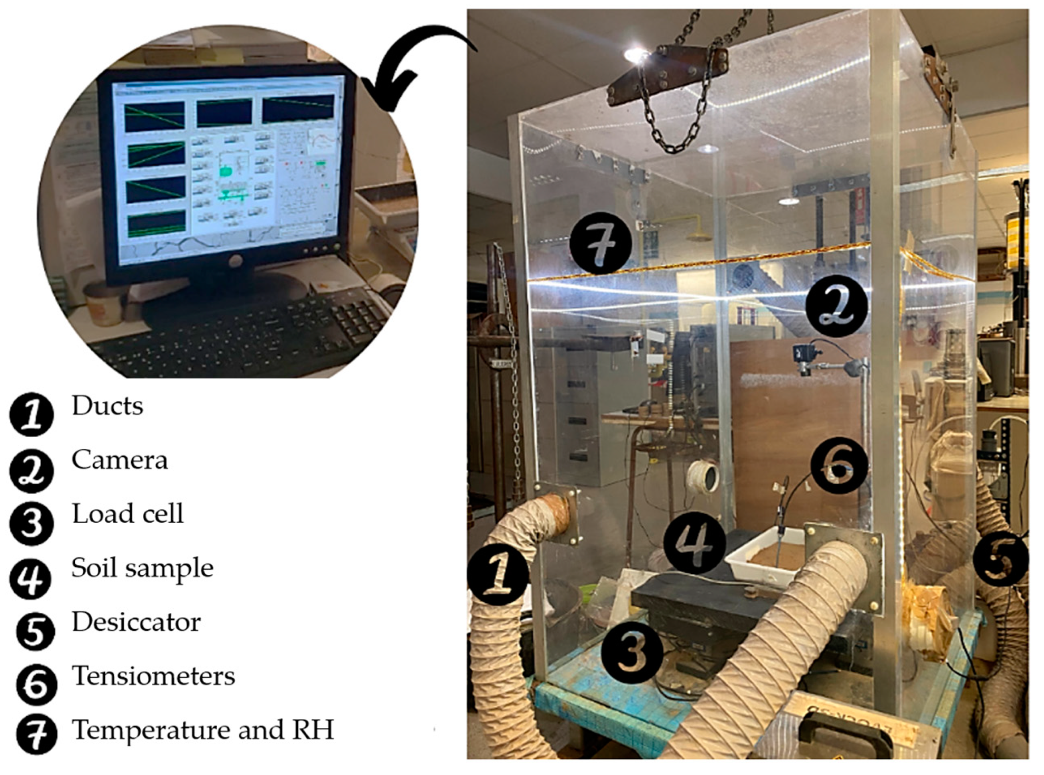
Figure 6.
Suction measurement: (a) with tensiometers inside the chamber; (b) with WP4C.

Figure 7.
Image analysis process using image J.

Figure 8.
Metrics from the images: (a) initial area, Ai; (b) shrinkage area, As (in black), and reduced area, Ar (in white); (c) area with cracks, Ac.
Figure 8.
Metrics from the images: (a) initial area, Ai; (b) shrinkage area, As (in black), and reduced area, Ar (in white); (c) area with cracks, Ac.

Figure 9.
Verification of the environmental conditions in the chamber.

Figure 10.
Effect of the PET and PP fiber content on desiccation over time.

Figure 11.
Cracking process of unreinforced soil.

Figure 12.
Desiccated PET soil samples.

Figure 13.
Desiccated PP soil samples.

Figure 14.
Progression of crack length and width.
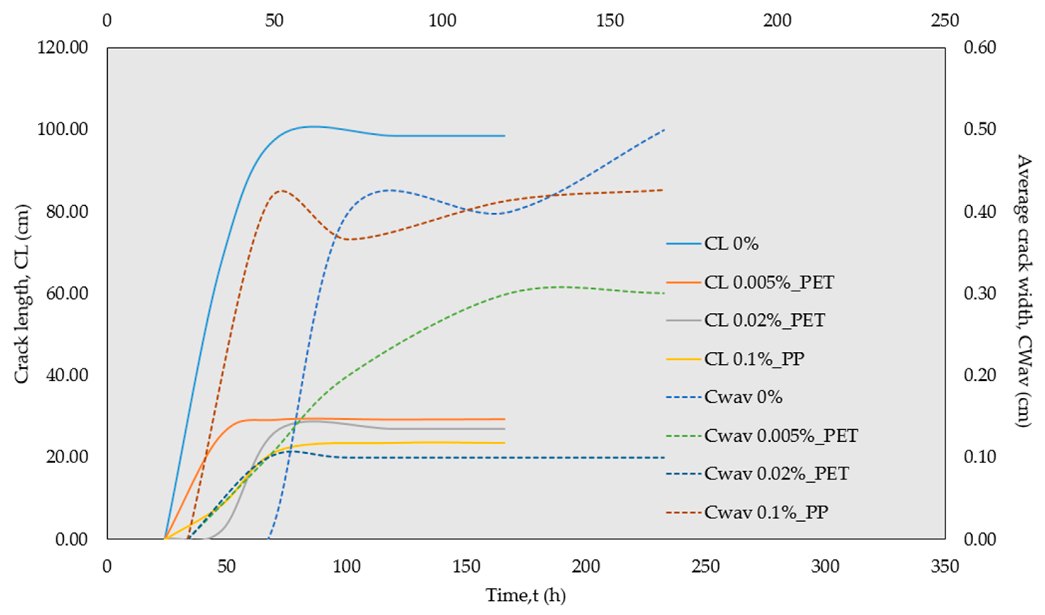
Figure 15.
Variation in the cracked (Ac) and shrinkage (As) areas.

Figure 16.
Variation in total crack intensity factor with fiber content.

Figure 17.
Variation in total crack intensity factor during desiccation.
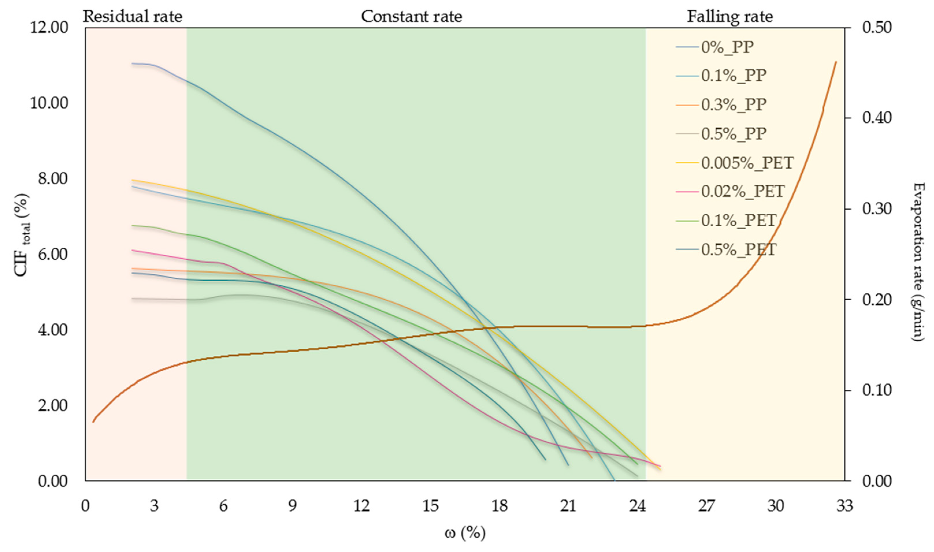
Figure 18.
Variation in suction during desiccation.


Table 1.
Characteristics of the reinforcement fibers.
| Fiber Type | L (mm) | D (μm) | Gs [59] | σt (MPa) [59] | E (MPa) [59] | εq (%) [59] | Tf (°F) [59] |
|---|---|---|---|---|---|---|---|
| PET | 50 | 15 | 0.92–0.96 | 76–586 | 4999 | 3–80 | 273 |
| PP | 13 | 31 | 0.9–0.91 | 138–689 | 3447–4826 | 15 | 330 |
Table 2.
Properties of the soil used [61].
Table 2.
Properties of the soil used [61].
| Index Properties | ||
| 2.7 | [62] | |
| 29 | [63] | |
| 17 | [63] | |
| 14 | [64] | |
| Plasticity index | 12 | [63] |
| Unified Soil Classification System (USCS) | CL | [65] |
| Number of additions of methylene blue (N) | 72 | [66] |
| Proctor compaction | ||
| 16 | [67] | |
| 17.8 | [67] | |
Table 3.
Tested samples in the environmental chamber.
| Code | Fiber | RH | T |
|---|---|---|---|
| % | % | °C | |
| 0.005%_PET | 0.005 | 29.94 | 24.38 |
| 0.02%_PET | 0.02 | 30.56 | 20.75 |
| 0.1%_PET | 0.1 | 29.59 | 23.24 |
| 0.5%_PET | 0.5 | 29.72 | 22.35 |
| 0%_PP | 0 | 30 | 22 |
| 0.1%_PP | 0.1 | ||
| 0.3%_PP | 0.3 | ||
| 0.5%_PP | 0.5 |
Disclaimer/Publisher’s Note: The statements, opinions and data contained in all publications are solely those of the individual author(s) and contributor(s) and not of MDPI and/or the editor(s). MDPI and/or the editor(s) disclaim responsibility for any injury to people or property resulting from any ideas, methods, instructions or products referred to in the content. |
© 2024 by the authors. Licensee MDPI, Basel, Switzerland. This article is an open access article distributed under the terms and conditions of the Creative Commons Attribution (CC BY) license (https://creativecommons.org/licenses/by/4.0/).
Share and Cite
MDPI and ACS Style
Hernández, C.; Beltrán, G.; Botero, E. Use of Recycled Plastic Fibers to Control Shrinkage and Desiccation Cracking in Clayey Soils. Sustainability 2024, 16, 3853. https://doi.org/10.3390/su16093853
AMA Style
Hernández C, Beltrán G, Botero E. Use of Recycled Plastic Fibers to Control Shrinkage and Desiccation Cracking in Clayey Soils. Sustainability. 2024; 16(9):3853. https://doi.org/10.3390/su16093853
Chicago/Turabian StyleHernández, Carolina, Gloria Beltrán, and Eduardo Botero. 2024. "Use of Recycled Plastic Fibers to Control Shrinkage and Desiccation Cracking in Clayey Soils" Sustainability 16, no. 9: 3853. https://doi.org/10.3390/su16093853
Note that from the first issue of 2016, this journal uses article numbers instead of page numbers. See further details here.