Elastic and Elastoplastic Contact Mechanics of Concentrated Coated Contacts †


1
School of Engineering, University of Central Lancashire, Preston PR1 2XQ, UK
2
Wolfson School of Mechanical, Electrical and Manufacturing Engineering, Loughborough University, Loughborough LE11 3TU, UK
*
Author to whom correspondence should be addressed.
†
This paper is an extended version of our paper published in Johns-Rahnejat, P.M.; Dolatabadi, N.; Rahnejat, H. Contact mechanics of highly loaded counterformal finite line contacts: Semi-infinite and layered elastic solids. In Proceedings of the LUBMAT 2023, Preston, UK, 17–19 July 2023.
Lubricants 2024, 12(5), 162; https://doi.org/10.3390/lubricants12050162
Submission received: 22 February 2024
/
Revised: 22 April 2024
/
Accepted: 3 May 2024
/
Published: 7 May 2024
(This article belongs to the Special Issue Selected Papers from the 8th Conference on Lubrication, Maintenance and Tribotechnology (LUBMAT))
Abstract
:Machines operate under increasingly harsher contact conditions, causing significant wear and contact fatigue. Sub-surface stresses are responsible for the premature contact fatigue of rolling element bearings, meshing gears, and cam–follower pairs. Surface protection measures include hard, wear-resistant coatings. Traditionally, contact integrity has been predicted using classical Hertzian contact mechanics. However, the theory is only applicable when the contact between a pair of ellipsoidal solids of revolution may be considered as a rigid indenter penetrating a semi-infinite elastic half-space. Many coatings act as thin bonded elastic layers that undergo considerably higher pressures than those predicted by the classical theory. Furthermore, inelastic deformation of bonded solids can cause plastic flow, work-hardening, and elastoplastic behaviour. This paper presents a comprehensive, integrated contact mechanics analysis that includes induced sub-surface stresses in concentrated counterformal finite line contacts for all the aforementioned cases. Generated pressures and deformation are predicted for hard coated surfaces, for which there is a dearth of relevant analysis. The contact characteristics, which are of particular practical significance, of many hard, wear-resistant advanced coatings are also studied. The paper clearly demonstrates the importance of using efficient semi-analytical, detailed holistic contact mechanics rather than the classical idealised methods or empirical numerical ones such as FEA. The novel approach presented for the finite line contact of thin-layered bonded solids has not hitherto been reported in the open literature.
1. Introduction
Progressively, many rolling and sliding contacts are subjected to high, variable, and often impulsive loads. These include the meshing of gear teeth pairs in automotive transmissions or differentials [1,2,3,4] or in wind turbines subjected to external variable wind and gust loading [5,6]. Variations in applied and impulsive loads, and in some cases, the misalignment of rolling element bearings, can cause excessive contact stresses that often result in the fatigue of mating surfaces and their eventual failure [7,8]. With ever-increasing harsh operational conditions, there are high incidences of bearing failure [5,8]. These require costly repair and often result in long system downtimes. Therefore, a detailed analysis of the mechanics of contact, particularly the evaluation of generated sub-surface stresses, is essential in the assessment of a design and the prediction of system performance [9,10,11,12,13]. Sub-surface stresses are affected by contact conformity [14,15] as well as by the choice of surface materials.
Many load-bearing surfaces are protected by thin, hard-coated layers [16,17]. In contact mechanics parlance, these coatings are referred to as bonded elastic solids [18,19]. It has long been established that the contact mechanics of thin bonded layers deviate from the classical Hertzian theory, which assumes the contacting solids to be semi-infinite (meaning that the principal dimensions of the contacting solids are at least two orders of magnitude larger than their contact footprint dimensions [15]. The footprint itself is also 2–3 orders of magnitude larger than the localised contact deformation (which is usually in the order of tenths to a few micrometres) [15,18,19]. With thin coatings of a few micrometres in thickness, the semi-infinite assumption cannot be upheld [18,19]. Therefore, the contact mechanics of thin bonded layered solids require their own theoretical treatment [15,16,17,18,19,20,21,22,23,24]. Most analytical solutions treat the coating as a single layer covering an assumed rigid or homogeneous elastic substrate. For more complex multi-layered bonded layers or treatment of the coatings as graded solids (where the modulus of elasticity alters gradually into the depth of coated surfaces), finite element analysis (FEA) is often used, such as in the study reported by Goltsberg and Etsion [25], who investigated the effect of various contact parameters such as the thinness of the coating as well as its hardness. Other studies using FEA with plane strain and plane stress conditions that also take the effect of friction into account include that of Xu et al. [26].
Some studies have dealt with graded elasticity in the mechanics of contact [27,28,29]. There are many surface hardening methods besides the usual coating methods, which introduce a distinct bonded layer, such as RF sputtering, chemical vapour deposition (CVD), and physical vapour deposition (PVD). These methods create hardened surfaces of the substrate material itself, such as anodizing and laser hardening. In effect, they create a protective surface, the contact mechanics of which depend on the characteristics of the top layer, such as its depth and hardness. Some representative literature includes [30,31]. This study excludes this class of contacting surfaces.
Under harsh operating conditions of high applied normal loads and high shear, some coatings can be subjected to localised plastic deformation, fracture, or exfoliation from the substrate [32,33,34]. Hence, contact mechanics under elastoplastic conditions should also be considered. FEA studies provide an approach for determining the onset of plasticity in elastic solids and layered coatings [25,35], and the method has been used to investigate the contact parameters related to the transitioning to the elastic–plastic regimes of deformation [35]. Although FEA can include truly 3D models of the problem considering plane strain and plane stress assumptions, they are computationally time-intensive. Simpler analytical models are advantageous, such as the approach highlighted here.
When sub-surface contact stresses exceed elastic deformation, indicating the onset of yielding [36], plastic flow can occur and, in many cases, some degree of work hardening takes place. As a result, the generated contact pressures are limited by the process of yielding, plastic flow, and work hardening. There have been many studies of this process, with the case of bilinear hardening described in some detail in [37,38,39]. Various yield criteria are employed, which depend on material ductility as well as applied loading configuration, such as pure normal loading, inclusion of shear, and friction. In general, FEA-based models use the von Mises yield criterion to investigate the sub-surface stresses and subsequent failure. However, it should be noted that the Tresca criterion is favoured for the cases of hard and brittle coatings, whereas for ductile substrates, the onset of failure, particularly for bearings and gears, is because of orthogonal reversing shear stresses [15,40,41].
Overall, the accurate prediction of contact stresses requires the development and use of appropriate methodologies. In many instances, classical Hertzian contact mechanics is inappropriately applied where the prevailing conditions significantly deviate from Hertzian core assumptions of a semi-infinite elastic half-space and small strain deformation within the elastic limit. This paper presents detailed analytical contact mechanics for finite line concentrated counterformal contacts, including sub-surface stress evaluation for semi-infinite elastic solids and thin bonded elastic layers under elastic and/or elastoplastic conditions.
2. Contact Mechanics of Semi-Infinite Finite Line Contacts
Meshing gear teeth, contact of rolling element bearing-to-races, and cam–follower pairs can be represented by an equivalent rigid ellipsoidal solid of revolution against a semi-infinite elastic half-space of equivalent modulus of elasticity by classical Hertzian contact mechanics, where (Figure 1):
and
The footprint contact area is an imprint that an equivalent rigid roller of radius R makes on a semi-infinite elastic half-space of equivalent elastic modulus. The contact footprint is a long and narrow rectangular strip with a half-width of for this assumed idealised infinite line contact [42,43]:
The lateral cross-sectional pressure profile is assumed to be elliptical, with a uniform longitudinal pressure distribution (Figure 1). The central pressure is as follows:
The parabolic approximation of the cross-sectional elliptical pressure profile is as follows:
The deflection anywhere within the thin rectangular contact footprint can be obtained as follows:
where for contacting surfaces of the same material (plane strain effective modulus).
The central contact deflection becomes [42]
Therefore, the footprint of an elastic line contact is fully described by classical Hertzian contact theory [43]. However, the Hertzian elastic line contact is idealised. In practice, the contact of a rigid roller with an elastic half-space generates a dog-bone (dumbbell) shaped footprint with the contact extremities spreading out due to the stress discontinuity at the roller’s sharp ends (Figure 2). In this case, the contact configuration is termed finite line contact, and a numerical approach is usually required to obtain the pressure distribution. A number of numerical solutions have been reported, including the initial solutions for the case of elastostatic contact of cylindrical roller bearings under assumed dry contact condition [44,45,46,47].
For finite line contacts, a numerical solution is required, where the contact footprint is sub-divided into a number of overlapping rectangular elements, as shown in Figure 2, with parabolic pressure profiles in the lateral direction and isosceles triangular pressure distributions in the longitudinal direction (Figure 3). The deflection at any point (x, y) within a computational element is obtained as follows:
The following relations are used to non-dimensionalise Equation (8):
Thus
where is the integration term in the non-dimensional form of Equation (8) with respect to , yielding [37,38]
where and: .
This yields the boundary integral equation (see Appendix A for its solution).
3. The Case of Bonded Elastic Layered Solids
Increasingly, contacting surfaces are coated for a variety of reasons. They include the use of thin, hard, wear-resistant coatings such as diamond like carbon (DLC), alumina, silicon nitride, bismuth, or indium. Their contact mechanics deviates from that described above, meaning that the semi-infinite assumption cannot be upheld.
For the case of hard-bonded layered elastic solids, Johnson [15] states that for the bonded layer thickness (half-width of contact footprint), plane sections remain plane, and
Eliminating and replacing from
yields
where
The above relations hold true for compressible layers , which account for most coatings. However, for incompressible layers, Equation (16) returns a value of infinity, which is clearly erroneous. Johnson [15] provides expressions for incompressible layers in line contact, whilst the same for circular point contacts is provided in [48]. Naghieh et al. [19] state that thin layered bonded solids are indicated by .
4. Contact Mechanics of Elastoplastic Layered Solids
Many coatings act tribologically to mitigate wear and/or friction. Additionally, solid lubricants behave like coatings, particularly to reduce friction. In many cases, bonded elastic layers (coatings, tribofilms and solid lubricants) deform elastoplastically, in some cases breaking down and reforming, particularly those with lower hardness [38,49,50,51]. The elastoplastic response follows the rate-independent plasticity theory, which incorporates a yield criterion, plastic flow, and work hardening [52,53]. For predictive analysis of elastoplastic response, a yield criterion is required. In the current analysis, Huber’s distortion energy hypothesis [54] is used, where the equivalent stress, , based on the generated sub-surface stresses is as follows:
where is the yield stress of the bonded layer, and
The sub-surface stresses can be obtained analytically, as shown in [9,14] (the case of reversing orthogonal shear stress is discussed later).
With no work hardening, Huber’s distortion energy hypothesis limits the generated pressures prior to yielding. However, some degree of work hardening occurs after localised plastic straining. This means that to obtain realistic contact conditions, work-hardening should be taken into account, where changes in plastic straining are obtained as follows:
where is the plastic stress potential (yield function) and is the material local plastic straining coefficient. Equation (19) assumes that plastic strain occurs in a direction normal to the yield surface. For kinematic hardening and von Mises equivalent stress yield criterion (assumed here):
where is the deviatoric stress vector and is the yield translation shift vector:
Solution of Equations (18)–(22) yields the limiting stress which should comply with the condition (17). Then, the generated elastoplastic contact pressures are: .
5. Method of Solution
For any rigid cylinder indenting an elastic plane, a trial load is initially used to evaluate the contact conditions, and . Then, an initial estimate of central contact deflection is made for either case of semi-infinite or bonded layered elastic solid. An initial rectangular contact footprint, as in idealised line contact, is assumed. Any misaligned contact condition can also be taken into account, though is not considered in the current study. All negative deflections are discarded as the method is only applicable to compressive conditions. Subsequently, the influence matrix is evaluated and the pressure distribution is obtained (see Appendix A). The following convergence criterion should be met
If the criterion is not satisfied, then the procedure is repeated, as shown in the flowchart in Figure 4. The flow chart includes every step of computational procedure, stating the equation numbers in the expounded methodology.
To obtain the final solution, the equilibrium condition must be satisfied. This means that the contact reaction (integrated pressure distribution) should equate to the applied contact load within a specified error tolerance:
The flow chart in Figure 4 provides a step-by-step computational procedure for the overall contact mechanics methodology expounded in this paper, with equation numbers provided for each step.
6. Determination of Sub-Surface Stress Field
Having obtained the pressure distribution, the induced sub-surface stresses that can be responsible for the inelastic deformation of the contacting surfaces are calculated. Fatigue spalling/pitting may occur when the stresses reach their elastic limit and coincide with sub-surface material flaws, such as voids or inclusions. For ductile bearing materials, the determining sub-surface stresses are the orthogonal reversing shear stresses, subjecting the material layers to repetitive cycles of compression/tension [14,40,41]:
where (into the depth of the contacting solid) and is the sub-surface reversing orthogonal shear stress distribution in each cross-section along the width of the contact in the -direction. For hard and brittle surfaces, the Tresca maximum shear stress criterion is applicable, as discussed later.
7. Results and Discussion
Figure 5 shows a typical axial pressure profile for a straight-edged (unprofiled) roller ( indenting a semi-infinite elastic half-space subjected to a contact load of 3683.6 N, based on a total bearing reaction , obtained using [42,55] where N = 12:
This expression is for the bottom roller (the highest loaded roller) with zero clearance in a horizontal shaft and bearing system. The other rollers experience lower contact forces at any instant of time. With zero clearance, the top roller is often completely unloaded.
The footprint for a finite line contact is a dumbbell or dog-bone shape with end extremities spreading out due to an abrupt change of profile (Figure 5b). The lateral pressure profile for the roller is elliptical at all cross-sections (profiles at sections A and B are shown in Figure 5c,d, respectively).
Figure 5c,d also show predicted sub-surface shear stresses, which are often responsible for inelastic deformation. Note: along the footprint longitudinal axis. The results here are for a ductile steel roller.
Owing to the progressively harsh operating conditions, bearings are often coated with protective hard layers. Data regarding some of these hard coatings are listed in Table 1. Cobalt–chromium bearing steel is included in the table as it is the usual substrate material. Most hard coatings have a similar moduli of elasticity to that of bearing steel, but they are much harder. Due to this and their thinness, the contact footprint is much narrower (in the lateral -direction) when the bearing is subjected to the same contact load. Correspondingly, much higher pressures are generated. This is shown in Figure 6 for the same roller dimensions and contact load as that in Figure 5.
The results in Figure 6 demonstrate that whilst the semi-infinite elastic assumption (Neo-Hertzian analysis) is appropriate for the steel roller, it clearly leads to serious erroneous predictions for rollers which are furnished with thin, hard, wear-resistant coatings. This is because such coatings are significantly harder than the substrate steel and yield thinner footprints under the same applied load. Consequently, much higher pressures are generated which, in turn, result in increased sub-surface stresses.
For example, in the case of alumina and DLC-coated rollers, the generated pressures are almost five times higher than when the coatings are considered to be semi-infinite elastic half-spaces. Correspondingly, the contact semi-half-width is nearly a quarter of that for a semi-infinite assumption. This means that the contact footprint is reduced with hard coatings, whilst the generated pressures significantly increase (the area under the distributions remains the same for the entire 3D pressure distribution over the contact footprint, representing the applied contact load).
The failure of hard coatings often occurs through fracture when maximum shear stress exceeds the condition prescribed by the Tresca criterion [56]:
In particular, coatings can exfoliate from the substrate if this maximum shear stress coincides with the interfacial layer between the coating and the substrate. Although the generated pressures are quite large ( values in Figure 6), the Tresca criterion is not readily reached because the elastic limit, is high for these hard coatings; for example, for alumina. Thus, for alumina as a layered bonded solid in Figure 6:
For the case of DLC, the axisymmetric lateral contact pressure profiles are for the case of coating considered as a semi-infinite half-space and when it is considered as an elastic layer (from Figure 6). These are used to obtain the maximum shear stress distribution beneath the surface: [14,56].
Figure 7 shows the centre cut through the maximum sub-surface shear stress distribution for both cases of DLC as semi-infinite elastic half-space and as thin layered elastic solid (into the depth of surface, z).
For the section through the centre of the contact, the sub-surface maximum shear stress distribution contains its absolute maximum value. It is clear that for the case of DLC, as an elastic layer, the maximum shear stress is closer to the contact surface than when the layer is assumed to be a semi-infinite substrate. The magnitude of the maximum shear stress is also significantly higher than when it is assumed to be a semi-infinite elastic half-space (nearly five times larger). This is in excess of its yield stress, breaching the Tresca yielding criterion for hard surfaces (as also indicated by Equation (28)). The zoomed inset to Figure 7 shows that the absolute maximum shear stress penetrates well beyond the usual DLC coating thickness of 2 µm. This means that at such a high contact load (3683.6 N), the hard DLC coating does not confine the maximum shear stress within its thickness, which is a requirement to protect the substrate beneath it. This action is envisaged as the raison d’etre of hard coatings. Therefore, the correct contact mechanics predictive approach shows that a high sub-surface maximum shear stress, breaching the confine of the coating thickness, could result in its exfoliation or fracture in practice under these conditions. Therefore, the in-depth predictive approach enables the correct hard coating to be selected for given loading conditions.
Cases of roller-to-races contacts for uncoated (semi-infinite elastic condition) and for coated (thin bonded elastic layers) conditions presented thus far were reported at LUBMAT 2023 [57].
Referring back to Figure 6 and Figure 7, it is clear that in practice, pressures of the order of several GPa (as in the case of layers of silicon nitride, alumina and DLC) cannot be sustained because the elastic layers become elastoplastic.
Figure 8 shows the lateral pressure profiles for the case of a steel roller coated with a thin 5 µm layer of TiC (physical/mechanical data for TiC is also provided in Table 1). The hard, wear-resistant coating should retain all the generated sub-surface contact stresses within its thickness, thus protecting the steel substrate. Therefore, to simplify the analysis, the contact is considered to be that of a thin layer bonded to a rigid substrate. The pressure distribution for this thin elastic layer, subjected to a contact load of 555 N, is shown in Figure 8. Note that the peak pressure is in excess of 4 GPa, which is far higher than that for a steel substrate (similar to the findings in Figure 6). As a hard elastic coating, the equivalent sub-surface stress should not exceed its yield stress (Equation (17)), or the Tresca criterion should not be exceeded, as described above for a hard coating. Taking this into account and treating the contact problem as a thin elastoplastic layer, the generated pressures are significantly less, as can be seen in Figure 8. The flow of material post plastic deformation and work hardening limits the generated pressures to a peak plateau of 1.25 GPa, extending the contact footprint in all the cross-sections of the overall dog-bone shaped finite line contact. Figure 8 shows the pressure distributions at the centre of the contact footprint.
Figure 9 shows the sub-surface maximum shear stress at the centre of the contact for the pressure profiles shown in Figure 8. As in the case of the DLC coating, the maximum shear stress penetrates into the substrate area (see the zoomed inset to the figure), implying that the elastic behaviour is exceeded, and an elastoplastic analysis is required.
The maximum shear stresses in both types of analysis, layered elastic or elastoplastic, are coincident. This indicates that considering the coating as a bonded layer is, in fact, appropriate. After all, the ratio , () where, as noted in [15,18,48], this ratio is indicative of bonded elastic layer behaviour. For the contact mechanics of a semi-infinite elastic half-space (the substrate bearing material): . For both these contact conditions, this paper provides comprehensive analytical contact mechanics and sub-surface analysis. For the intervening conditions, where , one has to resort to numerical analysis using finite differences, finite elements, or boundary element approaches. There have been many solutions in this regard, including [25,26,58,59,60,61]. Elastoplastic analysis using FEA or the semi-analytical approach, some including material hardening and some with the effect of adhesion, include [20,34,62,63,64,65,66,67].
Figure 9 shows that the maximum shear stress has exceeded the Tresca criterion: , where for TiC coatings. However, with the generated stresses exceeding the equivalent stress (Equation (18)), elastoplastic analysis with plastic flow and work-hardening has already occurred. This limits the generated pressures, as shown in Figure 8, as well as the maximum sub-surface shear stress for the case of elastoplastic behaviour (i.e., ). These results indicate compliance with the Tresca criterion. However, the analysis has already indicated a breach of the equivalent stress criterion as well as the maximum shear stress occurring at a depth below the coating layer. The methodology is realistic, holistic, and very practical.
8. Concluding Remarks
The paper shows that it is essential to use an appropriate contact mechanics analysis method to accurately predict the prevailing conditions for thin coated surfaces. It is rather commonplace to use idealised infinite line contacts with assumed semi-infinite elastic half-spaces (i.e., Hertzian contact mechanics). These assumptions can lead to serious underestimation of the generated pressures and the sub-surface stress field, which in turn can induce the fatigue spalling/pitting, fracture, or exfoliation of coatings. Additionally, thin layers can deform inelastically, undergo material plastic flows and work harden in some cases. These phenomena determine the real load-carrying capacity of contacts, not one based on idealised assumptions and theories. The work presented in this paper addresses all these issues and provides predictions that are much closer to real conditions than the usual idealised approaches.
The paper presents semi-analytical integrated contact mechanics for semi-infinite and layered bonded elastic solids with sub-surface evaluation and potential elastoplastic deformation. This is a holistic approach and an original contribution not hitherto reported in the open literature for the case of thin, hard, wear-resistant coatings in finite line contacts, which is of immediate practical use in the industry.
The paper itself makes certain simplifying assumptions. These include isothermal analysis, whereas high contact pressures induce some degree of compressive heating, even under elastostatic conditions. A thermal analysis would be more appropriate. Finally, the apparent area of contact is used for all the analyses, which is strictly valid for ideal smooth surfaces or nominally flat run-in surfaces. In reality, real rough surfaces have much smaller contact areas. In such cases, more complex numerical analyses would be required [68,69,70].
Author Contributions
Conceptualisation: P.M.J.-R.; methodology: all; software: P.M.J.-R. and N.D.; validation: all; formal analysis: all; investigation: all; data curation: N.D.; original drafting: P.M.J.-R. and H.R.; writing: all; review and editing: all; visualization: N.D.; supervision: P.M.J.-R. and H.R.; project administration: P.M.J.-R. All authors have read and agreed to the published version of the manuscript.
Funding
This research was partially funded by the British Ministry of Defence and partially by Science Research Council (now EPSRC).
Data Availability Statement
This research is not accompanied by any additional supporting data.
Acknowledgments
The authors wish to express their gratitude to the Science Research Council (now EPSRC) and the Ministry of Defence, Royal Aircraft Establishment (RAE) for their financial support resulting in the development of some of the methodologies used in this paper.
Conflicts of Interest
The authors declare no conflicts of interest.
Nomenclature
| Roman Symbols | |
| Semi-half-width at the centre of the contact | |
| Semi-half-width at any contact cross-section | |
| Layer thickness | |
| Half-width of rectangular computational element | |
| Roller diameter | |
| Effective Young’s modulus of elasticity | |
| Modulus of elasticity of contacting bodies | |
| Modulus of elasticity of the layer | |
| Equilibrium modulus of elasticity | |
| Effective elastic modulus of the contact | |
| Bearing reaction | |
| Modulus of rigidity | |
| Length roller (Contact footprint length) | |
| Number of rollers in the bearing | |
| Number of computational elements | |
| Pressure | |
| Central contact pressure | |
| Maximum pressure of any computational element | |
| Effective contact radius | |
| Contact load | |
| Co-ordinates of a point of deflection | |
| Co-ordinates of a point of pressure | |
| Co-ordinate into the depth of elastic solid | |
| Greek Symbols | |
| Yield translation shift | |
| Deflection | |
| Deflection at the centre of the contact | |
| Direct Stress: x, y along the surface, z into the depth of contact | |
| Equivalent stress | |
| Yield stress | |
| Plastic strain | |
| Limit of convergence for pressures | |
| Limit of convergence for elastostatic equilibrium | |
| Localised plastic strain coefficient | |
| Poisson’s ratio | |
| Poisson’s ratio for the layer | |
| Plastic strain potential | |
| Orthogonal reversing shear stress | |
| Maximum shear stress | |
Appendix A
The boundary integral equation is
The function in the boundary integral Equation (A1) is non-symmetrical about all four quadrants of the computational element shown in Figure 3. Therefore, to find the total deflection at the centre of each computational element, it is necessary to combine the contributions from all the four elemental quadrants in Figure 3:
The total deflection at the centre of any rectangular computational element, , becomes
where is any element within a total of n overlapping rectangular elements used to discretise the contact footprint and are the quadrants in each rectangular computational element.
Using Equations (A2) and (A3) and multiplying both sides by the term , the following relationship is obtained for the jth nodal point:
where , and is obtained from Equation (A1).
In dimensionless form:
Hence, to evaluate the unknown pressure distribution:
References
- Mohammadpour, M.; Johns-Rahnejat, P.M.; Theodossiades, S.; Rahnejat, H. Effect of tapered roller bearing supports on the dynamic behaviour of hypoid gear pair differentials. Proc. IMechE Part D J. Automob. Eng. 2016, 230, 1090–1104. [Google Scholar] [CrossRef]
- Xu, H.; Kahraman, A. Prediction of friction-related power losses of hypoid gear pairs. Proc. IMechE Part K J. Multi-Body Dyn. 2007, 221, 387–400. [Google Scholar] [CrossRef]
- Sivayogan, G.; Dolatabadi, N.; Johns-Rahnejat, P.; Rahmani, R.; Rahnejat, H. Non-Newtonian Thermo-Elastohydrodynamics and Sub-Surface Stress Field of High-Performance Racing Spur Gears. Lubricants 2022, 10, 146. [Google Scholar] [CrossRef]
- Sivayogan, G.; Rahmani, R.; Rahnejat, H. Transient non-Newtonian elastohydrodynamics of rough meshing hypoid gear teeth subjected to complex contact kinematics. Tribol. Int. 2022, 167, 107398. [Google Scholar] [CrossRef]
- Greco, A.; Sheng, S.; Keller, J.; Erdemir, A. Material wear and fatigue in wind turbine systems. Wear 2013, 302, 1583–1591. [Google Scholar] [CrossRef]
- Liu, H.; Liu, H.; Zhu, C.; He, H.; Wei, P. Evaluation of contact fatigue life of a wind turbine gear pair considering residual stress. J. Tribol. 2018, 140, 041102. [Google Scholar] [CrossRef]
- Liu, Z.; Zhang, L. A review of failure modes, condition monitoring and fault diagnosis methods for large-scale wind turbine bearings. Measurement 2020, 149, 107002. [Google Scholar] [CrossRef]
- Yucesan, Y.A.; Viana, F.A. A physics-informed neural network for wind turbine main bearing fatigue. Int. J. Progn. Health Manag. 2020, 11, 1–17. [Google Scholar] [CrossRef]
- Johns-Rahnejat, P.M.; Gohar, R. Point contact elastohydrodynamic pressure distribution and sub-surface stress field. In Proceedings of the Tri-Annual Conference on Multi-Body Dynamics: Monitoring and Simulation Techniques, Bradford, UK, 13 March 1997. [Google Scholar]
- Harris, T.A.; Yu, W.K. Lundberg-Palmgren fatigue theory: Considerations of failure stress and stressed volume. J. Tribol. 1999, 121, 85–89. [Google Scholar] [CrossRef]
- Slack, T.; Sadeghi, F. Explicit finite element modeling of subsurface initiated spalling in rolling contacts. Tribol. Int. 2010, 43, 1693–1702. [Google Scholar] [CrossRef]
- Sadeghi, F. Elastohydrodynamic lubrication. In Tribology and Dynamics of Engine and Powertrain; Woodhead Publishing: Cambridge, UK, 2010; pp. 171–226. [Google Scholar]
- Rahnejat, H.; Rahmani, R.; Mohammadpour, M.; Johns-Rahnejat, P.M. Tribology of power train systems. ASM Handb. 2017, 18, 916–934. [Google Scholar]
- Johns-Rahnejat, P.M.; Dolatabadi, N.; Rahnejat, H. Analytical elastostatic contact mechanics of highly-loaded contacts of varying conformity. Lubricants 2020, 8, 89. [Google Scholar] [CrossRef]
- Johnson, K.L. Contact Mechanics; Cambridge University Press: Cambridge, UK, 1985. [Google Scholar]
- Hannah, M. Contact stress and deformation in a thin elastic layer. Q. J. Mech. Appl. Math. 1951, 4, 94–105. [Google Scholar] [CrossRef]
- Barber, J.R. Contact problems for the thin elastic layer. Int. J. Mech. Sci. 1990, 32, 129–132. [Google Scholar] [CrossRef]
- Jaffar, M.J. Asymptotic behaviour of thin elastic layers bonded and unbonded to a rigid foundation. Int. J. Mech. Sci. 1989, 31, 229–235. [Google Scholar] [CrossRef]
- Naghieh, G.R.; Rahnejat, H.; Jin, Z.M. Characteristics of frictionless contact of bonded elastic and viscoelastic layered solids. Wear 1998, 232, 243–249. [Google Scholar] [CrossRef]
- Konvopoulos, K.; Gong, Z.Q. Effect of surface patterning on contact deformation of elastic–plastic layered media. J. Tribol. 2003, 125, 16–24. [Google Scholar]
- Teodorescu, M.; Rahnejat, H.; Gohar, R.; Dowson, D. Harmonic decomposition analysis of contact mechanics of bonded layered elastic solids. Appl. Math. Model. 2009, 33, 467–485. [Google Scholar] [CrossRef]
- Teodorescu, M.; Rahnejat, H. Mathematical modelling of layered contact mechanics of cam–tappet conjunction. Appl. Math. Model. 2007, 31, 2610–2627. [Google Scholar] [CrossRef]
- Chidlow, S.J.; Teodorescu, M. Two-dimensional contact mechanics problems involving inhomogeneously elastic solids split into three distinct layers. Int. J. Eng. Sci. 2013, 70, 102–123. [Google Scholar] [CrossRef]
- Menga, N.; Putignano, C.; Afferrante, L.; Carbone, G. The contact mechanics of coated elastic solids: Effect of coating thickness and stiffness. Tribol. Lett. 2019, 67, 1–10. [Google Scholar] [CrossRef]
- Goltsberg, R.; Etsion, I. Contact area and maximum equivalent stress in elastic spherical contact with thin hard coating. Tribol. Int. 2016, 93, 289–296. [Google Scholar] [CrossRef]
- Xu, K.; Chu, N.R.; Jackson, R.L. An investigation of the elastic cylindrical line contact equations for plane strain and stress considering friction. Proc. IMechE Part J J. Eng. Tribol. 2022, 236, 1889–1897. [Google Scholar] [CrossRef]
- Giannakopoulos, A.E.; Pallot, P. Two-dimensional contact analysis of elastic graded materials. J. Mech. Phys. Solids 2000, 48, 1597–1631. [Google Scholar] [CrossRef]
- Attia, M.A.; El-Shafei, A.G. Modeling and analysis of the nonlinear indentation problems of functionally graded elastic layered solids. Proc. IMechE Part J J. Eng. Tribol. 2019, 233, 1903–1920. [Google Scholar] [CrossRef]
- Çömez, İ. Contact mechanics of the functionally graded monoclinic layer. Eur. J. Mech.-A/Solids 2020, 83, 104018. [Google Scholar] [CrossRef]
- Lyubicheva, A.N.; Mezrin, A.M.; Kuznetsov, V.A.; Torskaya, E.V. Effect of Viscous Intermediate Layer on Uneven Wear of Locally Hardened Steel. Tribol. Lett. 2024, 72, 21. [Google Scholar] [CrossRef]
- Horng, J.H.; Osipenko, N.M.; Stepanov, F.I.; Torskaya, E.V. Theoretical and experimental study of changes in the structure of the intermediate layer during friction between contacting bodies. Materials 2021, 14, 5689. [Google Scholar] [CrossRef]
- Karami, G. Boundary element analysis of elasto-plastic contact problems. Comput. Struct. 1991, 41, 927–935. [Google Scholar] [CrossRef]
- Fischer-Cripps, A.C.; Lawn, B.R.; Pajares, A.; Wei, L. Stress analysis of elastic-plastic contact damage in ceramic coatings on metal substrates. J. Am. Ceram. Soc. 1996, 79, 2619–2625. [Google Scholar] [CrossRef]
- Komvopoulos, K. Elastic-Plastic Finite Element Analysis of Indented Layered Media. J. Tribol. 1989, 111, 430–439. [Google Scholar] [CrossRef]
- Chen, Z.; Goltsberg, R.; Etsion, I. A universal model for a frictionless elastic-plastic coated spherical normal contact with moderate to large coating thicknesses. Tribol. Int. 2017, 114, 485–493. [Google Scholar] [CrossRef]
- Song, W.; Li, L.; Ovcharenko, A.; Jia, D.; Etsion, I.; Talke, F.E. Plastic yield inception of an indented coated flat and comparison with a flattened coated sphere. Tribol. Int. 2012, 53, 61–67. [Google Scholar] [CrossRef]
- Brake, M.R. An analytical elastic plastic contact model with strain hardening and frictional effects for normal and oblique impacts. Int. J. Solids Struct. 2015, 62, 104–123. [Google Scholar] [CrossRef]
- Ghaednia, H.; Wang, X.; Saha, S.; Xu, Y.; Sharma, A.; Jackson, R.L. A review of elastic–plastic contact mechanics. Appl. Mech. Rev. 2017, 69, 060804. [Google Scholar] [CrossRef]
- Sharma, A.; Jackson, R.L. A finite element study of an elasto-plastic disk or cylindrical contact against a rigid flat in plane stress with bilinear hardening. Tribol. Lett. 2017, 65, 1–2. [Google Scholar] [CrossRef]
- Gohar, R.; Rahnejat, H. Fundamentals of Tribology, 3rd ed.; World Scientific Publishing: Singapore, 2018. [Google Scholar]
- Ioannides, E.; Harris, T.A. A New Fatigue Life Model for Rolling Bearings. J. Tribol. 1985, 107, 367–378. [Google Scholar] [CrossRef]
- Johns, P.M. The Design of Cylindrical Rollers for Use in Shaft and Bearing Systems. Master’s Thesis, Imperial College of Science and Technology, London, UK, 1978. [Google Scholar]
- Hertz, H. The contact of elastic solids. J. Reine Angew. Math. 1881, 92, 156–171. [Google Scholar]
- Kannel, J.W. Comparison between Predicted and Measured Axial Pressure Distribution between Cylinders. J. Lubr. Technol. 1974, 96, 508–514. [Google Scholar] [CrossRef]
- Heydari, M.; Gohar, R. The Influence of the Axial Profile on Pressure Distribution in Radially Loaded Rollers. J. Mech. Eng. Sci. 1979, 21, 381–388. [Google Scholar] [CrossRef]
- Johns, P.M.; Gohar, R. Roller bearings under radial and eccentric loads. Tribol. Int. 1981, 14, 131–136. [Google Scholar] [CrossRef]
- Johns-Rahnejat, P.M.; Karami, G.; Aini, R.; Rahnejat, H. Fundamentals and advances in elastohydrodynamics: The role of Ramsey Gohar. Lubricants 2021, 9, 120. [Google Scholar] [CrossRef]
- Teodorescu, M.; Votsios, V.; Rahnejat, H. Fundamentals of impact dynamics of semi-infinite and layered solids. In Tribology and Dynamics of Engine and Powertrain; Woodhead Publishing: Cambridge, UK, 2010; pp. 105–132. [Google Scholar]
- Becker, V.; Kamlah, M. A theoretical model for the normal contact force of two elastoplastic ellipsoidal bodies. J. Appl. Mech. 2021, 88, 031006. [Google Scholar] [CrossRef]
- Persson, B.N. Elastoplastic contact between randomly rough surfaces. Phys. Rev. Lett. 2001, 87, 116101. [Google Scholar] [CrossRef] [PubMed]
- Kogut, L.; Etsion, I. Elastic-plastic contact analysis of a sphere and a rigid flat. J. Appl. Mech. 2002, 69, 657–662. [Google Scholar] [CrossRef]
- Haupt, P. On the mathematical modelling of material behavior in continuum mechanics. Acta Mech. 1993, 100, 129–154. [Google Scholar] [CrossRef]
- Mielke, A.; Roubíček, T. Rate-independent elastoplasticity at finite strains and its numerical approximation. Math. Models Methods Appl. Sci. 2016, 26, 2203–2236. [Google Scholar] [CrossRef]
- Huber, M.T. Zur Theorie der beruhrung fester elastischer korper. Ann. Phys. 1904, 14, 153–163. [Google Scholar] [CrossRef]
- Lundberg, G.; Palmgren, A. Dynamic capacity of rolling bearings. J. Appl. Mech. 1949, 16, 165–172. [Google Scholar] [CrossRef]
- Tresca, M.H. On further applications of the flow of solids. Proc. IMechE 1878, 29, 301–345. [Google Scholar] [CrossRef]
- Johns-Rahnejat, P.M.; Dolatabadi, N.; Rahnejat, H. Contact mechanics of highly loaded counterformal finite line contacts: Semi-infinite and layered elastic solids. In Proceedings of the Lubrication, Maintenance and Tribotechnology (LUBMAT 2023), Preston, UK, 17–19 July 2023. 10p. [Google Scholar]
- Holmberg, K.; Laukkanen, A.; Ronkainen, H.; Wallin, K.; Varjus, S.; Koskinen, J. Tribological contact analysis of a rigid ball sliding on a hard coated surface: Part I: Modelling stresses and strains. Surf. Coat. Technol. 2006, 200, 3793–3809. [Google Scholar] [CrossRef]
- Nikas, G.K.; Sayles, R.S. Finite-element analysis of layered rolling contacts. Proc. IMechE Part J J. Eng. Tribol. 2008, 222, 865–886. [Google Scholar] [CrossRef]
- Yilmaz, K.B.; Çömez, I.; Güler, M.A.; Yildirim, B.O. Analytical and finite element solution of the sliding frictional contact problem for a homogeneous orthotropic coating-isotropic substrate system. ZAMM-J. Appl. Math. Mech./Z. Für Angew. Math. Und Mech. 2019, 99, e201800117. [Google Scholar] [CrossRef]
- Tang, K.C.; Arnell, R.D. Determination of coating mechanical properties using spherical indenters. Thin Solid Film. 1999, 355, 263–269. [Google Scholar] [CrossRef]
- Komvopoulos, K.; Ye, N. Three-dimensional contact analysis of elastic-plastic layered media with fractal surface topographies. J. Trib. 2001, 123, 632–640. [Google Scholar] [CrossRef]
- Sun, Y.; Bloyce, A.; Bell, T. Finite element analysis of plastic deformation of various TiN coating/substrate systems under normal contact with a rigid sphere. Thin Solid Films 1995, 271, 122–131. [Google Scholar] [CrossRef]
- Li, L.Y.; Wu, C.Y.; Thornton, C. A theoretical model for the contact of elastoplastic bodies. Proc. IMechE Part C J. Mech. Eng. Sci. 2001, 216, 421–431. [Google Scholar] [CrossRef]
- Frohne, J.; Heister, T.; Bangerth, W. Efficient numerical methods for the large-scale, parallel solution of elastoplastic contact problems. Int. J. Numer. Methods Eng. 2016, 105, 416–439. [Google Scholar] [CrossRef]
- Jin, T.; Yin, X.; Zhang, L.; Wang, H.; Yu, B.; Hao, Q. Strain-rate-dependent model for the elastoplastic dynamic contact of sphere and plate. Mater. Res. Express 2020, 7, 066523. [Google Scholar] [CrossRef]
- Qi, K.; Zhou, Q.; Yang, W.; Yang, J. A semi-analytical approach for elastoplastic impact-contact involving coated medium. Int. J. Solids Struct. 2023, 283, 112467. [Google Scholar] [CrossRef]
- Chang, W.R.; Etsion, I.; Bogy, D.B. An elastic-plastic model for the contact of rough surfaces. J. Tribol. 1987, 109, 257–263. [Google Scholar] [CrossRef]
- Persson, B.N. Contact mechanics for randomly rough surfaces. Surf. Sci. Rep. 2006, 61, 201–227. [Google Scholar] [CrossRef]
- Chen, Z.; Etsion, I. Recent development in modeling of coated spherical contact. Materials 2020, 13, 460. [Google Scholar] [CrossRef] [PubMed]
Figure 1.
Idealised elastic line contact of cylindrical solids of revolution.

Figure 2.
Dog-bone-shaped footprint of finite line contact with elemental discretisation.

Figure 3.
Computational element.

Figure 4.
Computational flowchart.

Figure 5.
Contact mechanics prediction of finite line contact geometry: (a) contact pressure distribution, (b) contact footprint, (c) subsurface shear stress at the centre of contact, and (d) subsurface shear stress at the edge of contact.
Figure 5.
Contact mechanics prediction of finite line contact geometry: (a) contact pressure distribution, (b) contact footprint, (c) subsurface shear stress at the centre of contact, and (d) subsurface shear stress at the edge of contact.

Figure 6.
Comparison of generated pressure distribution for semi-infinite and layered bonded solid (coated) surfaces (half symmetric lateral pressure profiles at the contact centre are shown).
Figure 6.
Comparison of generated pressure distribution for semi-infinite and layered bonded solid (coated) surfaces (half symmetric lateral pressure profiles at the contact centre are shown).

Figure 7.
Sub-surface central contact maximum shear stress variation into contact depth.

Figure 8.
Elastic and elastoplastic contact mechanics of layered bonded solids.
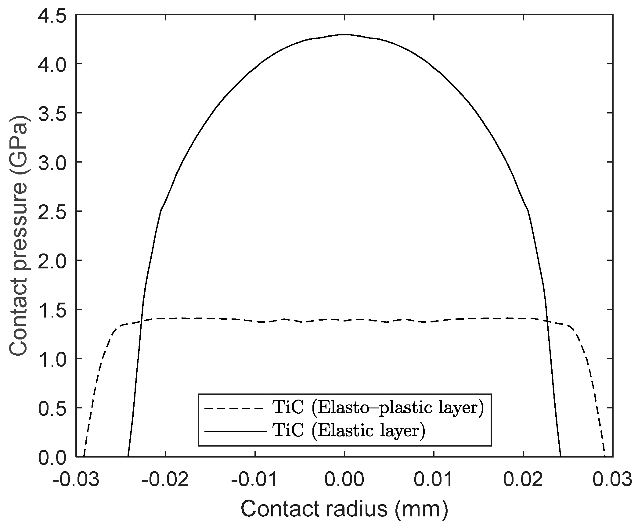
Figure 9.
Sub-surface shear stress variation for elastic and elastoplastic coatings.


Table 1.
Mechanical properties of solid half space and layered solids.
| Material | Modulus of Elasticity, E (GPa) | Poisson’s Ratio | Layer Thickness, b (µm) |
|---|---|---|---|
| Steel | 206 | 0.30 | − |
| Si3N4 | 250 | 0.20 | 6 |
| Al2O3 | 300 | 0.21 | 3 |
| DLC | 220 | 0.21 | 2 |
| TiC | 400 | 0.18 | 5 |
Disclaimer/Publisher’s Note: The statements, opinions and data contained in all publications are solely those of the individual author(s) and contributor(s) and not of MDPI and/or the editor(s). MDPI and/or the editor(s) disclaim responsibility for any injury to people or property resulting from any ideas, methods, instructions or products referred to in the content. |
© 2024 by the authors. Licensee MDPI, Basel, Switzerland. This article is an open access article distributed under the terms and conditions of the Creative Commons Attribution (CC BY) license (https://creativecommons.org/licenses/by/4.0/).
Share and Cite
MDPI and ACS Style
Johns-Rahnejat, P.M.; Dolatabadi, N.; Rahnejat, H. Elastic and Elastoplastic Contact Mechanics of Concentrated Coated Contacts. Lubricants 2024, 12, 162. https://doi.org/10.3390/lubricants12050162
AMA Style
Johns-Rahnejat PM, Dolatabadi N, Rahnejat H. Elastic and Elastoplastic Contact Mechanics of Concentrated Coated Contacts. Lubricants. 2024; 12(5):162. https://doi.org/10.3390/lubricants12050162
Chicago/Turabian StyleJohns-Rahnejat, Patricia M., Nader Dolatabadi, and Homer Rahnejat. 2024. "Elastic and Elastoplastic Contact Mechanics of Concentrated Coated Contacts" Lubricants 12, no. 5: 162. https://doi.org/10.3390/lubricants12050162
Note that from the first issue of 2016, this journal uses article numbers instead of page numbers. See further details here.