

Effects of Embedded Expanded Polystyrene Boards on the Hysteretic Behavior of Innovative Precast Braced Concrete Shear Walls
1
State Key Laboratory of Coastal and Offshore Engineering, Faculty of Infrastructure Engineering, Dalian University of Technology, Dalian 116024, China
2
School of Civil Engineering, Shenyang Jianzhu University, Shenyang 110168, China
*
Author to whom correspondence should be addressed.
Buildings 2024, 14(1), 55; https://doi.org/10.3390/buildings14010055
Submission received: 9 November 2023
/
Revised: 16 December 2023
/
Accepted: 21 December 2023
/
Published: 24 December 2023
(This article belongs to the Special Issue Seismic Risk Analysis and Management of Structure Systems)
Abstract
:An innovative type of precast braced concrete shear (PBCS) wall has been tested and verified to have comparable shear resistances relative to conventional cast-in-place reinforced concrete (RC) shear walls. The triangular or rectangular embedded expanded polystyrene (EPS) boards in PBCS wall panels can not only considerably reduce concrete use but also reduce the structural weight. To understand the functions of EPS boards in more depth, this paper investigates the effects of the thickness ratio of different shapes of EPS on the hysteretic behaviors of PBCS walls with various shear span ratios (SSRs). The finite element (FE) models of PBCS walls based on the multi-layer shell element are developed and verified to be sufficiently accurate in comparison with the experimental results. The analysis results indicate that the bearing capacity, lateral stiffness and ductility of PBCS walls show a downward trend with the increase in the thickness ratio of EPS boards. The rectangular EPS board has a more pronounced effect on weight reduction as well as concrete use reduction compared to the triangular EPS board under the same thickness ratio. The formulations regarding the bearing capacity are developed and show good agreement with the numerical results. The thickness ratio limit for PBCS walls to satisfy the ductility requirement is addressed. This investigation not only provides insight into the cyclic behavior of PBCS walls with varied thickness ratios but also demonstrates the potential applicability of PBCS walls in precast concrete (PC) structures for both thermal insulation and earthquake resistance purposes.
1. Introduction
Nowadays, the precast concrete (PC) technology is widely promoted for application in reinforced concrete (RC) structures. It is more compatible with the development of a low-carbon society and the application of sustainable construction relative to the conventional cast-in-place method [1,2]. The utilization of the PC technology in shear walls makes it possible for walls with complex structural layouts and with composite actions to be fabricated beforehand in factory and further assembled on site. Moreover, previous research works showed that lowering the use of concrete can not only reduce carbon emissions but also degrade the structural weight [3,4]. Therefore, the effort related to the weight reduction of PC shear walls, which simultaneously retains sufficient lateral shear resistances and composite actions, is necessary as well as promising.
Considerable attempts have been performed to lighten the shear walls by means of employing various lightweight aggregates or devising novel structural configurations. Mousavi et al. [5] and Lombardi et al. [6] carried out hysteretic cyclic loading tests on lightweight concrete shear walls using expanded glass and expanded polystyrene (EPS) concrete (EPS mortar with low strength) as lightweight aggregates, respectively. According to the findings of their investigations, the overall weight of the panels was decreased by more than 50%, while the hysteretic behavior of the wall, particularly its ductility and energy dissipation capacity, was diminished significantly. Pakizeh et al. [7], Xu et al. [8,9,10] and Ximei et al. [11] discussed the cyclic behaviors of shear wall casting with high compressive strength lightweight concrete. It was concluded that the high compressive strength of lightweight concrete was finitely beneficial to improving the cyclic behaviors of composite wall systems. In addition to efforts in that regard, many researchers focused on the development of novel wall designs to achieve considerable composite actions of the shear walls, as well as the demands of light weight. Composite timber shear walls [12,13,14,15,16] and RC shear walls with hollow cavities [17,18,19] are two representatives of lightweight shear wall systems widely applied in engineering practice. However, due to the material’s limitations in terms of durability and fireproofing requirements, wood shear walls are mostly used in low-rise and mid-rise constructions.
The sandwich wall panel is another typical composite lightweight wall system, which is commonly composed of two concrete wythes sandwiched by the extruded polystyrene (XPS) or EPS board as the insulation layer [20]. Fernando et al. [21] investigated the cyclic behavior of sandwich wall panels with EPS foam concrete as insulation wythe and found that sandwich wall structures can work as load bearing walls in single-story buildings or as infilled walls in multi-story buildings. To improve the degree of composite action of sandwich wall panels, Yaman [22] and Barbosa et al. [23] developed lightweight sandwich concrete wall panels featuring considerable thermal insulation property, which were proved functionable under push-out tests and axial loading tests, respectively. Lu et al. [24] and He et al. [25] conducted shaking table tests on PC sandwich wall panel structures (with XPS and EPS boards embedded, respectively). Fragility analysis was performed additionally to verify the reliability of the connections of walls in low-rise buildings. However, the composite action depended considerably on the shear transferring mechanism between concrete wythes of sandwich walls, which was generally partly achieved [20]. Thus, the wall integrity as well as stiffness were decreased. Given the increasing building restrictions and the composite actions of the above-mentioned wall systems, the precast braced concrete shear (PBCS) wall system with different shapes of embedded EPS boards and RC bracings was developed [26]. The hysteretic response of PBCS walls with various shear span ratios (SSRs) and RC bracing types was experimentally studied and validated.
Previous research has revealed that the thermal insulation performance of sandwich wall panels with embedded polystyrene boards [27] outperforms that of sandwich wall panels with lightweight thermal insulation concrete as the aggregate [28]. Specifically, XPS boards and EPS boards are generally used as the thermal insulation layer in practical engineering [29,30]. The EPS board outperforms the XPS board in terms of weight reduction, as its density is about 1/3 that of the XPS and 1/150 that of concrete [31]. The XPS board is widely adopted in the foundations of buildings [31] and the cut sections of railways [32] due to its low thermal conductivity and high compressive strength. However, the degree of composite actions of walls with insulation layers is greatly affected by the adhesive bond between the insulation and concrete wythes [33,34,35]. Naito et al. [36] found that wall panels with EPS layers had higher adhesive forces compared with those of walls with XPS insulation. The PBCS wall studied in this paper also used the EPS board as the insulation material. Moreover, experimental data concluded that the thermal insulating performance [27] of sandwich wall panels increased along with the rise in thickness of the insulation wythe, while the axial bearing capacity [30] as well as lateral shear resistances [37,38,39,40] had an obvious decrease. Above all, the thickness of insulation would remarkably affect the structural weight, thermal insulating performance and hysteretic behavior of sandwich shear walls.
It is obvious that increasing the thickness of triangular or rectangular lightweight EPS boards in PBCS wall panels can not only considerably reduce concrete use but also strengthen the thermal insulating performance of PBCS walls, which meets the tendency of developing energy-saving buildings. However, the increase in lightweight EPS board thickness is more likely to lead to weak shear resistance and poor ductility capacity of PBCS walls. The previous study mainly focused on investigating the influences of axial load ratio (ALR) and reinforcement ratio (RR) on the cyclic behavior of PBCS walls [41]. In this paper, the effects of EPS board thickness on the hysteretic behaviors of PBCS walls with various SSRs and bracing types are quantified by numerical simulation methods. Moreover, the formulae predicting the lateral bearing capacity of PBCS walls with different thicknesses of EPS boards are developed. The upper limits of EPS board thickness ratio for different PBCS walls are put forward to satisfy the requirement of displacement ductility. The effects of SSR and bracing types are also taken into consideration. The finite element (FE) models of PBCS walls considering different EPS board thicknesses are established and verified against the test data regarding the initial stiffness. Afterward, FE models with different thickness ratios of EPS boards are determined, established and tested under cyclic loading. The hysteretic behaviors of PBCS walls are comprehensively discussed in terms of stiffness degradation, load bearing capacity, energy dissipation capacity and ductility capacity. Additionally, the thickness ratio limits for PBCS walls are obtained to satisfy the provisions on ductility of shear walls. Finally, recommendations for the practical design of PBCS walls are addressed based on the analytical results.
2. Experimental Work
2.1. PBCS Wall Description
The hysteretic behaviors of PBCS walls with different SSRs and bracing types were experimentally investigated in the previous study performed by Li et al. [26]. The structural layouts of PBCS walls with diagonal braces and cross braces embedded are listed in Figure 1a,b, respectively. There were seven specimens, with SSRs varying from 1.0 to 2.0 (three diagonal PBCS walls, three cross PBCS walls and one monolithic cast in situ RC wall as the counterpart). It should be noted that the number of triangular EPS boards in diagonal PBCS walls remained constant at four, while that in cross PBCS walls ranged from four to eight as the SSR increased, as shown in Figure 1. Diagonal PBCS walls consisted of two diagonal braces, which intersected at the middle of the wall and expanded into the top and bottom beams, respectively. One vertical brace and several horizontal braces were embedded in the cross PBCS wall panels. The number of horizontal braces was determined by the principle of equivalent volumetric ratio of the diagonal braces in the corresponding PBCS walls with the same SSR.
The reinforcement scheme for the two types of PBCS walls is shown in Figure 2. The concealed columns in PBCS walls contained 6C14 steel bars (with yielding strength fy = 410 MPa and ultimate strength fu = 610 MPa), which were connected with the base beam to transfer the tensile forces. The concealed RC bracings consisting of 4C8 steel bars were arranged in the panels in order to achieve a more even distribution of damage. There were two concealed beams (6C10 as longitudinal bars) set at the top and bottom of PBCS wall panels, respectively. The Φ6.5 steel bars (with yielding strength fy = 420 MPa and ultimate strength fu = 580 MPa) spaced at 150 mm were adopted in the horizontal and vertical web reinforcement. In addition, the compressive strength of concrete in this paper was 28.2 MPa.
Table 1 presents the specimen information, such as geometric dimensions and reinforcement configurations, in detail. The wall depth and length were 150 mm and 1500 mm, respectively. The wall height varied between 1500 mm and 3000 mm with the increase in SSR. The thickness of EPS boards was 50 mm for both triangular and rectangular boards used in the experiment. The naming convention for each specimen (also applicable for the FE models below) is illustrated in Table 1. The first two letters represent the bracing types of PBCS walls (i.e., CW = PBCS walls with cross braces; DW = PBCS walls with diagonal braces). The first number after the letter denotes the SSR of the specimen, and the last number in the name indicates the thickness of embedded EPS boards in centimeters (cm) for the sake of clarity. The thickness ratio of EPS boards in PBCS walls can be obtained from the ratio of the thickness of EPS board to that of the wall panel. The adoption of thickness ratio can extend the investigation to various wall thicknesses rather than being limited to a fixed wall thickness.
2.2. Test Program
All specimens were fabricated at the scale of approximately 0.75 and were tested under vertical load and lateral cyclic load (Figure 3). The ALR applying to the loading beam herein was a constant of 0.1. The axial load was first applied to the rigid beam and remained stable throughout the test. Then, the displacement-controlled lateral load was uniformly increased to a drift ratio of Δy = 0.33% in five incremental levels (loaded once for every loading level). Afterward, the lateral load increased by 0.33% of the drift ratio (loaded twice for every loading level), and the test was finally terminated when the lateral resistances of the specimen decreased by 15% or wall failure occurred. During the experimental process, the lateral displacement at the top of the wall and the shear resistances at the base beam of the wall were recorded.
3. Numerical Simulation Methods and Validation
As mentioned above, it is meaningful to quantify the influence of thickness ratio on the hysteretic response of PBCS walls. However, because of the high cost, as well as the limited number of specimens, the effect of thickness ratio is not fully discussed. This section presents the FE models of PBCS walls based on the multi-layer shell element [42], and then, the numerical results are verified with experimental data. On this basis, the FE models of PBCS walls with consideration of parameters, such as the bracing type, SSR and especially the thickness ratio of EPS board, are established, and their hysteretic behaviors are obtained through quasi-static loading.
3.1. Description and Establishment of FE Model of PBCS Walls
The multi-layer shell element discretizes the FE model of the wall panel into several layers with specified thicknesses and different material properties [42]. This approach is adopted for modeling PBCS walls, since it can take into account the thickness and shape of the EPS board. The FE models herein consist of the modeling of longitudinal reinforcements and multi-layer shell elements, both of which work together and share common nodes. The multi-layer shell elements are composed of numerous layers of cover and core concrete, as well as stirrup layers (Figure 4). The truss element is utilized to simulate the behaviors of longitudinal reinforcements. In particular, the stirrup layer of diagonal braces is established with the angle between the diagonal brace and the concealed boundary column. The horizontal and vertical web reinforcement layers are set at 0° and 90°, respectively. Additionally, the material properties are valued according to experimental results. Since the density of the EPS board (16 kg/m3) is much lower than that of the concrete (2500 kg/m3), it is suitable to simulate the EPS board as a hollow core. It should be noted that the constitutive models for concrete and steel adopted in this paper are PlaneStressUserMaterial [42] and Reinforcing Steel Material [43], respectively. All numerical simulation analyses were conducted on the OpenSEES platform (V2.5.0) [44].
The thickness ratio of PBCS walls herein refers to the ratio of EPS thickness to wall panel thickness. As mentioned before, the thickness of the EPS board embedded in the shear walls would dramatically affect the structural weight and concrete use. On the premise of code compliance of the cover concrete, the thickness of the EPS board inside ranges from 10 mm to 100 mm, with an even interval of 10 mm, which corresponds to thickness ratios varying between 0.067 and 0.667. The concrete layer thickness in the multi-layer shell element of PBCS walls corresponding to the embedding EPS areas is changed to achieve the different thickness ratios. Overall, 60 FE models featuring various thickness ratios are established, coupling the parameters of SSRs and bracing types. The hysteresis responses of the models are quantitatively analyzed and discussed.
3.2. Validation of Numerical Models of PBCS Walls
Previous research has shown that the hysteresis behaviors, including energy dissipation capacity and lateral deformation capacity, of PBCS walls can be properly predicted by the multi-layer shell elements. Stiffness degradation, as an important factor of the hysteretic performance of shear walls, is taken herein to validate the accuracy of numerical models. Secant stiffness can be obtained by Equation (1).
where Ki, Fi, Δi denote the secant stiffness, lateral shear resistances and lateral top displacement of the ith cycle in both reverse loading directions.
Figure 5 presents the comparisons between numerical and experimental results on the stiffness degradation of PBCS walls. It is found that the FE model can depict the stiffness degradation of PBCS walls accurately. Nevertheless, the initial stiffness of the numerical model is generally greater than the experimental results. Kolozvari et al. [45] reviewed the FE modeling approaches for RC shear walls and found that all of the models overestimated the initial stiffness by even three times that of the experimental results. This was attributed to the presence of initial defects in the test specimens and micro-cracking in the concrete, which could not be properly simulated in FE modeling. However, stiffness degradation was less affected during the loading stage. As shown in Figure 5, the stiffness degradation curves matched well with experimental results after reaching a drift ratio of 0.67%.
4. Results and Discussion
4.1. Concrete Use Reduction
By increasing the thickness ratio of the EPS board, the structural weight of the PBCS wall can be efficiently reduced; the concrete use of the structure is also decreased. Figure 6 illustrates the impact of thickness ratio on weight reduction in PBCS walls. It is evident that the volume of the embedded EPS board increases significantly with the increase in SSR and thickness ratio, resulting in lower use of concrete. Furthermore, the volumetric ratio of the EPS board to the entire wall is calculated to obtain the normalized curves of weight reduction (Figure 6b). A near 20% reduction in concrete use is observed for the cross PBCS walls, which is 11.67% higher than the maximum value of the diagonal PBCS walls. Compared to conventional shear walls, PBCS walls have certain insulation functions with additional filling of the walls with EPS panels. Meanwhile, the amount of concrete used in PBCS walls can be remarkably reduced, which is beneficial for energy conservation and emission reduction. The integrity of PBCS walls outperforms that of sandwich PC walls by embedding EPS boards between the bracings.
4.2. Skeleton Curves
Skeleton curves can be acquired by connecting the peak points of each loading level in the hysteretic curves. A total of 60 skeleton curves are shown in Figure 7, according to different SSRs and bracing types. Each sub-image illustrates the skeleton curves of a PBCS wall with a specific SSR and bracing type, under varying thickness ratios. Additionally, Figure 7a–f scale the skeleton curve at a drift ratio of 0.67% to provide a more detailed view of the impact of thickness ratio on the wall’s lateral shear resistances.
It is found that all numerical models can satisfy the Chinese code GB 50011-2010 [46] when their lateral drift ratios reach 1/1000 as well as 1/120 (i.e., 0.83%), which represent the maximum inter-story drift angle for RC shear wall structures subjected to frequent and infrequent earthquakes, respectively. It is evident in Figure 7 that the shear capacity and lateral stiffness of PBCS walls decrease at all loading stages as the thickness ratio of the EPS board increases. This is because the use of concrete, which is the primary factor for bearing and transmitting compressive stress in the wall, is directly weakened. On the contrary, an increase in the thickness ratio leads to a slight enhancement in the ultimate displacement of the PBCS wall (Figure 7e).
Moreover, by comparing the skeleton curves of PBCS walls with different SSRs, it is concluded that the lateral elastic stiffness of PBCS walls with low SSRs experienced a more significant variation than that of walls with a high SSR (Figure 7a,b). This is in part because shear walls with low SSRs are more prone to shear failure characterized by concrete crushing. Additionally, the increase in the thickness ratio of the EPS board further weakens the bearing capacity provided by concrete. In addition, it is suggested in Figure 7a,e that the thickness ratio of the cross PBCS wall with a low SSR (SSR = 1.0) has a more noticeable impact on its hysteresis response relative to the other cases. However, the hysteresis response of the diagonal PBCS wall is more sensitive to the escalation in thickness ratio at a high SSR (SSR = 2.0).
The findings of the hysteresis analyses indicate that the composite actions for cross PBCS shear walls with a high SSR of 2.0 or diagonal PBCS walls with a low SSR of 1.0 can remain stable by increasing the thickness ratio of the EPS board. Specifically, this approach not only reduces the consumption of concrete and the overall weight of the structure, but it also ensures that the cyclic response of the PBCS wall will not be significantly affected by the increased thickness ratio.
4.3. Lateral Bearing Capacity
Figure 8 exhibits the lateral bearing capacity of PBCS walls with different SSRs, bracing types and thickness ratios of the EPS board. As shown in the figure, there is a gradual decrease in peak forces as the thickness ratio increases for both diagonal and cross layouts of PBCS walls. This is due to the reduction in concrete use. Nevertheless, a maximum decline of only 4.8% and 7.9% in lateral shear resistances is observed for the diagonal and cross PBCS walls, respectively, with a low SSR of 1.0. Additionally, it can be concluded from Figure 8 that the SSR outweighs the bracing type and thickness ratio in affecting the shear bearing capacity of PBCS walls.
The effect of the thickness ratio on the bearing capacity of PBCS walls demonstrates an approximately linear trend. Thus, fitting surfaces are performed to predict the peak shear resistances of PBCS walls regarding the SSR and thickness ratio. The results are listed as follows:
where PD and PC are the bearing capacities of the diagonal and cross PBCS walls (expressed in kN), respectively; RS denotes the SSR; and RT represents the thickness ratio of the EPS board (in percent). The R-squares of the fitting results are 0.977 and 0.969, respectively. The fitting equations here are shown to be applicable for accurately predicting the bearing capacity of PBCS walls. Due to the limited sample size, this formulation is only applicable when other parameters of PBCS walls are kept constant with the experimental setups.
4.4. Stiffness Degradation
To facilitate comparison, the stiffness–drift ratio curves of each loading level were derived by dividing the lateral displacement by the corresponding height of the wall, as shown in Figure 9. For simplicity, the lines presented in Figure 9 vary from light colors to dark colors, which correspond to the thickness ratio of the EPS board from 0.067 to 0.667. It can be observed that before the drift ratio reaches 0.67%, the stiffness in all cases decreases rapidly. During this stage, the maximum stiffness degradation occurs at SSR = 1.0, with stiffness of the cross PBCS wall and diagonal PBCS wall decreasing by 54.9% and 49.5%, respectively (compared to initial stiffness). The deterioration in stiffness during this stage is mainly attributed to the large number of concrete cracks generated in the early stage of loading. Subsequently, the lateral stiffness of the wall gradually decreases, with stiffness of the cross PBCS wall and diagonal PBCS wall descending, respectively, by 31.1% and 34.6% (compared to initial stiffness), from a drift ratio of 0.67%–2.0%. Stiffness degradation during this stage is mainly due to the further cracking of concrete and the ability of steel bars to provide resistance even after entering the plastic stage.
Furthermore, Figure 9 illustrates that the secant stiffness of the wall witnesses an evident drop with the increase in the EPS board thickness ratio when the horizontal displacement arrives at the same level, before the wall reaches its peak bearing capacity. However, after the drift ratio exceeds 1.33%, the impact of the EPS board thickness ratio on stiffness becomes negligible. This is due to the fact that the wall panel is full of concrete cracking, and stress redistribution occurs when the peak force stage shows up, rendering the EPS board ineffective as a hollow core. Additionally, the stiffness of PBCS walls with larger SSRs is slightly affected by the EPS board thickness ratio during the entire loading process. This can be attributed to the bending failure mode, which usually occurs in walls with higher SSRs, characterized by concrete crushing at the wall bottom and yielding longitudinal bars in the boundary columns. The damage to the upper and middle areas of the wall, where the EPS board is embedded, is small in extent, resulting in minor impact of the EPS board on stiffness.
To comprehensively investigate the influences of embedded EPS boards on the stiffness degradation of PBCS walls, the stiffness degradation curves of cases with similar amounts of EPS embedded are shown in Figure 10. When the thickness ratios of cross and diagonal PBCS walls are 0.467 and 0.533, respectively, the EPS volumes of the two types of PBCS walls are similar (with the same SSR). This means that in order to embed the same volume of the EPS board, the diagonal PBCS wall requires a thicker EPS board than the cross PBCS wall. Figure 10 shows that when the filling volumes are the same, the stiffness degradation process of the two types of walls is basically the same. The diagonal PBCS wall exhibits slightly greater stiffness than the cross PBCS wall during the loading process. This can be attributed to the fact that the diagonal bracing layout has higher stiffness compared to the cross bracing layout.
4.5. Displacement Ductility
Ductility of a shear wall is a crucial factor, which reflects its deformation capacity. It is typically represented by the ratio of ultimate displacement (Δ0.85p) to yielding displacement (Δy) of the wall. The yielding displacement of the wall is determined using the method proposed by Park et al. [47], while the ultimate displacement is obtained when the peak strength of the wall decreases by 15%, as illustrated in Figure 11. In this approach, α is the load coefficient, which is taken as 0.75.
Figure 12 illustrates the yielding displacement of PBCS walls with different bracing types. It is evident that the yielding displacement in all cases generally shows an upward trend when the EPS board thickness ratio rises. Shear walls typically reach yielding resistances (Fy) when the longitudinal reinforcing bar yield is reached. This depends considerably on the sectional area of longitudinal bars in the boundary columns, which is a constant in this study, and thus results in a stable Fy. Meanwhile, the stiffness of the wall tails off with the thickness ratio increases. In view of this, the corresponding yielding displacement of PBCS walls is increased to achieve the yielding resistances identified.
The ductility capacities of PBCS walls with different bracing types are presented in Figure 13. It can be seen that the ductility of the PBCS wall descends evidently with an increase in the thickness ratio. This can be explained by a previous study [41], which demonstrated that PBCS walls with high ALR are susceptible to low ductility capacities. Specifically, the increase in the thickness of the EPS board leads to a reduction in the net cross-sectional area of the wall. As a consequence, the ALR is improved in spite of the axial loads remaining constant. In addition, a horizontal line μ = 3.0 is presented in the figure to represent the code requirement that the ductility of the shear wall should not be lower than 3.0 [46]. It can be observed that the ductility of all diagonal PBCS walls can nearly meet the code requirements as the EPS board thickness ratio changes. In particular, the diagonal PBCS wall with SSR = 1.0 should be designed with a thickness ratio below 0.6 to satisfy the requirements of displacement ductility greater than 3.0. In addition, the ductility of the cross PBCS wall generally falls below the code requirements when the SSR is 1.0, indicating that the design schemes for cross PBCS walls with SSR = 1.0 or lower should be avoided.
4.6. Energy Dissipation
The accumulated energy dissipation refers to the energy dissipated from the beginning to the ith cycle of the loading scheme. Figure 14 demonstrates the accumulated energy dissipation curves for PBCS walls with different thickness ratios during the loading process. As the lateral drift ratio increases, the cumulative energy dissipation in each case exhibits a substantial increase. It is apparent that the thickness ratio of the EPS board does not affect the accumulated energy dissipation of the specimen until the eighth cycle, i.e., before the drift ratio reaches 0.83%. At this stage, the energy dissipation of the wall mainly occurs with the cracking of concrete on both sides of the boundary columns and deformation of the steel bars. The panel zone with the EPS board embedded remains nearly undamaged.
As the loading process progresses, the impact of the thickness ratio of EPS boards on the energy dissipation of PBCS walls becomes increasingly apparent. Concrete cracking extends toward the area filled with EPS boards and widens as the lateral drift increases. The greater the thickness ratio of the EPS board, the lower the resistance provided by the concrete in this area, resulting in a reduced energy dissipation capacity.
In addition, the energy dissipation of cross PBCS walls with SSRs of 1.0 and 1.5 is more sensitive to the variation in thickness ratio relative to diagonal PBCS walls (Figure 14a–d). The cross PBCS wall with SSR = 1.0 saw a fall of 20.7% (from 71.8 kJ to 57 kJ) in accumulated dissipated energy, while a decrease of only 7.8% (from 86.3 kJ to 79.5 kJ) was observed in the diagonal PBCS wall. PBCS walls with low SSRs are especially vulnerable to shear failure characterized by diagonal cracks, whereas the diagonal braces in PBCS walls can effectively slow down the development of these diagonal cracks. Therefore, diagonal PBCS walls with low SSRs behave better in terms of energy dissipation.
However, as the thickness ratio rises, diagonal PBCS walls with SSRs = 2.0 experience a more significant decline in energy dissipation compared to cross PBCS walls. Generally, walls with SSRs = 2.0 are more susceptible to a bending failure, with horizontal cracks appearing in the lower part of the wall, where cross braces can play a more effective role than diagonal ones. Therefore, for PBCS walls with SSRs of 1.0 and 1.5, diagonal braces with high thickness ratio could be adopted to achieve comparable energy dissipation capacity. For PBCS walls with SSRs = 2.0, it is more advisable to employ cross PBCS walls with a higher thickness ratio than diagonal ones.
5. Conclusions and Recommendations
In this paper, the effects of the thickness ratio of the EPS board on the cyclic behaviors of PBCS walls with different SSRs and bracing types were comprehensively investigated. Numerical models were developed and verified against experimental data in terms of stiffness degradation capacity. A total of 60 numerical cases were established with parameters such as the thickness ratio, SSR and bracing types. The hysteretic behaviors of PBCS walls were discussed with respect to skeleton curves, lateral bearing capacity, stiffness degradation, displacement ductility and energy dissipation. Based on the ductility requirements, the thickness ratio limits of EPS boards in PBCS walls with different bracing types were addressed. The main conclusions and recommendations can be summarized as follows:
- The stiffness degradation capacity of PBCS walls can be precisely captured by numerical models based on the multi-layer shell element. Moreover, increasing the thickness ratio of EPS boards in PBCS walls can significantly reduce the amount of concrete used. Cross PBCS walls witnessed a roughly 20% reduction in concrete use when the thickness ratio rose from 0.067 to 0.667, which was 11.67% higher than what the diagonal PBCS walls achieved.
- Based on the findings, the recommendations for determining the thickness of EPS panels are put forward for practical design of PBCS walls. When the thickness ratio of the EPS board increased, the lateral bearing capacity, secant stiffness and displacement ductility of the PBCS wall experienced a consistent decline, while the yielding displacement had a gradual upward trend. Specifically, the lateral bearing capacity of diagonal and cross PBCS walls experienced declines of 4.8% and 7.9%, respectively. In addition, the equations developed for predicting the bearing capacity of PBCS walls were demonstrated to be sufficiently accurate. Furthermore, to ensure the ductility is greater than 3.0, the diagonal PBCS wall with SSR = 1.0 should be designed with a thickness ratio below 0.6, and a cross PBCS wall with SSR = 1.0 should be avoided.
- The accumulated dissipated energy of cross PBCS walls (SSR = 1.0) and diagonal PBCS walls (SSR = 1.0) saw decreases of 20.7% and 7.8% with the EPS board thickness ascending, respectively. A diagonal PBCS wall with high thickness ratio of the EPS board could be adopted to achieve comparable energy dissipation capacity when the SSR is below 1.5. For the SSR of 2.0, cross PBCS walls are more suitable than diagonal ones, as they dissipate more energy.
- Owing to the limited scope of SSR involved in this study, the relevant suggestions obtained herein are applicable to PBCS walls with frequently configured SSR, ranging from 1.0 to 2.0. Like other RC shear wall modeling approaches, an overestimation of initial stiffness was also observed in the FE models of PBCS walls based on the multi-layer shell element. This is a promising study for optimizing the deficiency. A quantitative analysis of the influence of the EPS board thickness ratio on the thermal insulation performance of PBCS walls would be a valuable development in future studies. Additionally, in order to achieve better weight reduction effects for PBCS walls as well as further reduce concrete use, the adoption of new lightweight and high strength concrete materials and embedded thermal insulation layer in PBCS walls is also necessary.
Author Contributions
Conceptualization, H.L.; Methodology, Y.T.; Validation, Y.T.; Formal analysis, Y.T. and H.L.; Data curation, Y.T.; Writing—original draft, Y.T.; Writing—review & editing, H.L.; Supervision, H.L.; Project administration, H.L.; Funding acquisition, H.L. All authors have read and agreed to the published version of the manuscript.
Funding
This research is financially supported by the National Natural Science Foundation of China (No. 51738007).
Data Availability Statement
The data that support the findings of this study are available from the corresponding author upon reasonable request.
Conflicts of Interest
The authors declare no conflict of interest.
References
- Dong, Y.H.; Jaillon, L.; Chu, P.; Poon, C.S. Comparing carbon emissions of precast and cast-in-situ construction methods—A case study of high-rise private building. Constr. Build. Mater. 2015, 99, 39–53. [Google Scholar] [CrossRef]
- Kurama, Y.C.; Sritharan, S.; Fleischman, R.B.; Restrepo, J.I.; Henry, R.S.; Cleland, N.M.; Ghosh, S.K.; Bonelli, P. Seismic-Resistant Precast Concrete Structures: State of the Art. J. Struct. Eng. 2018, 144, 03118001. [Google Scholar] [CrossRef]
- Wibowo, A.; Wijatmiko, I.; Nainggolan, C.R. Cyclic Behaviour of Expanded Polystyrene (EPS) Sandwich Reinforced Concrete Walls. Adv. Mater. Sci. Eng. 2018, 2018, 7214236. [Google Scholar] [CrossRef]
- O’Hegarty, R.; Kinnane, O. Review of precast concrete sandwich panels and their innovations. Constr. Build. Mater. 2020, 233, 117145. [Google Scholar] [CrossRef]
- Lombardi, R.; Jünemann, R.; Lopez, M. Experimental assessment of the behavior of expanded glass lightweight reinforced concrete walls. J. Build. Eng. 2022, 49, 104043. [Google Scholar] [CrossRef]
- Mousavi, S.A.; Zahrai, S.M.; Bahrami-Rad, A. Quasi-static cyclic tests on super-lightweight EPS concrete shear walls. Eng. Struct. 2014, 65, 62–75. [Google Scholar] [CrossRef]
- Pakizeh, M.R.; Parastesh, H.; Hajirasouliha, I.; Farahbod, F. Seismic performance of CFS shear wall systems filled with polystyrene lightweight concrete: Experimental investigation and design methodology. Steel Compos. Struct. 2023, 46, 497. [Google Scholar]
- Xu, Z.; Chen, Z.; Yang, S. Effect of a new type of high-strength lightweight foamed concrete on seismic performance of cold-formed steel shear walls. Constr. Build. Mater. 2018, 181, 287–300. [Google Scholar] [CrossRef]
- Xu, Z.; Chen, Z.; Yang, S. Seismic behavior of cold-formed steel high-strength foamed concrete shear walls with straw boards. Thin-Walled Struct. 2018, 124, 350–365. [Google Scholar] [CrossRef]
- Xu, Z.; Chen, Z.; Dong, X.; Zuo, Y. Experimental Study on Seismic Behavior of Lightweight Concrete-Filled Cold-Formed Steel Shear Walls Strengthened Using Horizontal Reinforcement. J. Earthq. Eng. 2023, 27, 4126–4160. [Google Scholar] [CrossRef]
- Ximei, Z.; Jiayu, Y.; Can, C. Seismic performance and flexible connection optimization of prefabricated integrated short-leg shear wall filled with ceramsite concrete. Constr. Build. Mater. 2021, 311, 125224. [Google Scholar] [CrossRef]
- Chen, F.; Li, Z.; He, M.; Wang, Y.; Shu, Z.; He, G. Seismic performance of self-centering steel-timber hybrid shear wall structures. J. Build. Eng. 2021, 43, 102530. [Google Scholar] [CrossRef]
- Kuai, L.; Ormarsson, S.; Vessby, J.; Maharjan, R. A numerical and experimental investigation of non-linear deformation behaviours in light-frame timber walls. Eng. Struct. 2022, 252, 113599. [Google Scholar] [CrossRef]
- Orlowski, K.; Baduge, S.K.; Mendis, P. Prefabricated Composite Steel-Timber Stiffened Wall Systems with Post-Tensioning: Structural Analysis and Experimental Investigation under Vertical Axial Load. J. Struct. Eng. 2021, 147, 04020325. [Google Scholar] [CrossRef]
- Wang, R.; Wei, S.Q.; Li, Z.; Xiao, Y. Performance of connection system used in lightweight glubam shear wall. Constr. Build. Mater. 2019, 206, 419–431. [Google Scholar] [CrossRef]
- Darzi, S.; Karampour, H.; Bailleres, H.; Gilbert, B.P.; Fernando, D. Load bearing sandwich timber walls with plywood faces and bamboo core. Structures 2020, 27, 2437–2450. [Google Scholar] [CrossRef]
- Hamid, N.H.; Mander, J.B. Lateral Seismic Performance of Multipanel Precast Hollowcore Walls. J. Struct. Eng. 2010, 136, 795–804. [Google Scholar] [CrossRef]
- Dal Lago, B.; Muhaxheri, M.; Ferrara, L. Numerical and experimental analysis of an innovative lightweight precast concrete wall. Eng. Struct. 2017, 137, 204–222. [Google Scholar] [CrossRef]
- Wang, W.; Wang, X. Experimental and numerical investigations on concentrated-hollow RC shear walls. Eng. Struct. 2021, 242, 112570. [Google Scholar] [CrossRef]
- Pessiki, S.; Mlynarczyk, A. Experimental evaluation of the composite behavior of precast concrete sandwich wall panels. PCI J. 2003, 48, 54–71. [Google Scholar] [CrossRef]
- Fernando, P.L.N.; Jayasinghe, M.T.R.; Jayasinghe, C. Structural feasibility of Expanded Polystyrene (EPS) based lightweight concrete sandwich wall panels. Constr. Build. Mater. 2017, 139, 45–51. [Google Scholar] [CrossRef]
- Sevil Yaman, T.; Lucier, G. Shear Transfer Mechanism between CFRP Grid and EPS Rigid Foam Insulation of Precast Concrete Sandwich Panels. Buildings 2023, 13, 928. [Google Scholar] [CrossRef]
- Barbosa, K.; Silva, W.T.M.; Silva, R.; Vital, W.; Bezerra, L.M. Experimental Investigation of Axially Loaded Precast Sandwich Panels. Buildings 2023, 13, 1993. [Google Scholar] [CrossRef]
- Lu, Y.; Chen, W.; Xiong, F.; Yan, H.; Ge, Q.; Zhao, F. Seismic Performance of a Full-Scale Two-Story Bolt-Connected Precast Concrete Composite Wall Panel Building Tested on a Shake Table. J. Struct. Eng. 2021, 147, 04021209. [Google Scholar] [CrossRef]
- He, J.-X.; Xu, Z.-D.; Zhang, L.-Y.; Lin, Z.-H.; Hu, Z.-W.; Li, Q.-Q.; Dong, Y.-R. Shaking table tests and seismic assessment of a full-scale precast concrete sandwich wall panel structure with bolt connections. Eng. Struct. 2023, 278, 115543. [Google Scholar] [CrossRef]
- Li, H.-N.; Tang, Y.-C.; Li, C.; Wang, L.-M. Experimental and numerical investigations on seismic behavior of hybrid braced precast concrete shear walls. Eng. Struct. 2019, 198, 109560. [Google Scholar] [CrossRef]
- Yu, S.; Liu, Y.; Wang, D.; Ma, C.; Liu, J. Theoretical, experimental and numerical study on the influence of connectors on the thermal performance of precast concrete sandwich walls. J. Build. Eng. 2022, 57, 104886. [Google Scholar] [CrossRef]
- Liu, P.; Gong, Y.F.; Tian, G.H.; Miao, Z.K. Preparation and experimental study on the thermal characteristics of lightweight prefabricated nano-silica aerogel foam concrete wallboards. Constr. Build. Mater. 2021, 272, 121895. [Google Scholar] [CrossRef]
- Xu, G.; Li, A. Seismic performance of a new type precast concrete sandwich wall based on experimental and numerical investigation. Soil Dyn. Earthq. Eng. 2019, 122, 116–131. [Google Scholar] [CrossRef]
- Kumar, S.; Chen, B.; Xu, Y.; Dai, J.-G. Structural behavior of FRP grid reinforced geopolymer concrete sandwich wall panels subjected to concentric axial loading. Compos. Struct. 2021, 270, 114117. [Google Scholar] [CrossRef]
- Kilar, V.; Koren, D.; Bokan-Bosiljkov, V. Evaluation of the performance of extruded polystyrene boards—Implications for their application in earthquake engineering. Polym. Test. 2014, 40, 234–244. [Google Scholar] [CrossRef]
- Niu, F.; Jiang, H.; Su, W.; Jiang, W.; He, J. Performance degradation of polymer material under freeze-thaw cycles: A case study of extruded polystyrene board. Polym. Test. 2021, 96, 107067. [Google Scholar] [CrossRef]
- Gombeda, M.J.; Naito, C.J.; Quiel, S.E. Development and performance of a ductile shear tie for precast concrete insulated wall panels. J. Build. Eng. 2020, 28, 101084. [Google Scholar] [CrossRef]
- Gombeda, M.J.; Naito, C.J.; Quiel, S.E. Flexural performance of precast concrete insulated wall panels with various configurations of ductile shear ties. J. Build. Eng. 2021, 33, 101574. [Google Scholar] [CrossRef]
- Choi, I.; Kim, J.; Kim, D.; Park, J. Effects of grid-type shear connector arrangements used for insulated concrete sandwich wall panels with a low aspect ratio. J. Build. Eng. 2022, 46, 103754. [Google Scholar] [CrossRef]
- Naito, C.; Hoemann, J.; Beacraft, M.; Bewick, B. Performance and Characterization of Shear Ties for Use in Insulated Precast Concrete Sandwich Wall Panels. J. Struct. Eng. 2012, 138, 52–61. [Google Scholar] [CrossRef]
- Daniel Ronald Joseph, J.; Prabakar, J.; Alagusundaramoorthy, P. Experimental studies on through-thickness shear behavior of EPS based precast concrete sandwich panels with truss shear connectors. Compos. Part B-Eng. 2019, 166, 446–456. [Google Scholar] [CrossRef]
- Choi, W.; Jang, S.-J.; Yun, H.-D. Design properties of insulated precast concrete sandwich panels with composite shear connectors. Compos. Part B-Eng. 2019, 157, 36–42. [Google Scholar] [CrossRef]
- Xu, G.; Li, A. Experimental and numerical studies on the lateral performance of concrete sandwich walls. Struct. Des. Tall Spec. Build. 2020, 29, e1715. [Google Scholar] [CrossRef]
- Lameiras, R.; Barros, J.A.O.; Valente, I.B.; Poletti, E.; Azevedo, M.; Azenha, M. Seismic behaviour of precast sandwich wall panels of steel fibre reinforced concrete layers and fibre reinforced polymer connectors. Eng. Struct. 2021, 237, 112149. [Google Scholar] [CrossRef]
- Tang, Y.-C.; Li, H.-N.; Li, C. Parametric Studies on Seismic Performance of New Precast Braced Concrete Shear Walls under Cyclic Loading. J. Struct. Eng. 2023, 149, 04023061. [Google Scholar] [CrossRef]
- Lu, X.; Xie, L.; Guan, H.; Huang, Y.; Lu, X. A shear wall element for nonlinear seismic analysis of super-tall buildings using OpenSees. Finite Elem. Anal. Des. 2015, 98, 14–25. [Google Scholar] [CrossRef]
- Kunnath, S.K.; Heo, Y.; Mohle, J.F. Nonlinear Uniaxial Material Model for Reinforcing Steel Bars. J. Struct. Eng. 2009, 135, 335–343. [Google Scholar] [CrossRef]
- Mazzoni, S.; McKenna, F.; Scott, M.H.; Fenves, G.L. OpenSees command language manual. Pac. Earthq. Eng. Res. (PEER) Cent. 2006, 264, 137–158. [Google Scholar]
- Kolozvari, K.; Biscombe, L.; Dashti, F.; Dhakal, R.P.; Gogus, A.; Gullu, M.F.; Henry, R.S.; Massone, L.M.; Orakcal, K.; Rojas, F.; et al. State-of-the-art in nonlinear finite element modeling of isolated planar reinforced concrete walls. Eng. Struct. 2019, 194, 46–65. [Google Scholar] [CrossRef]
- GB 50011-2010; Ministry of Housing and Urban-Rural Development, PRC. Code for Seismic Design of Buildings. China Construction Industry Press: Beijing, China, 2016. (In Chinese)
- Park, R.; Priestley, M.J.N.; Gill, W.D. Ductility of Square-Confined Concrete Columns. J. Struct. Div. 1982, 108, 929–950. [Google Scholar] [CrossRef]
Figure 1.
Structural configurations of PBCS walls.

Figure 2.
Cutaway view of PBCS walls (SSR = 1.0).

Figure 3.
Schematics of test setup.

Figure 4.
Schematics of multi-layer shell element of PBCS walls (SSR = 2.0).

Figure 5.
Verification of the numerical models.

Figure 6.
Effects of thickness ratio on concrete use reduction.

Figure 7.
Skeleton curves of PBCS walls.

Figure 8.
Peak forces of PBCS walls with different thicknesses of EPS board.

Figure 9.
Stiffness degradation of PBCS walls.

Figure 10.
Stiffness degradation of PBCS walls with similar amounts of EPS.

Figure 11.
Feature points based on skeleton curve.
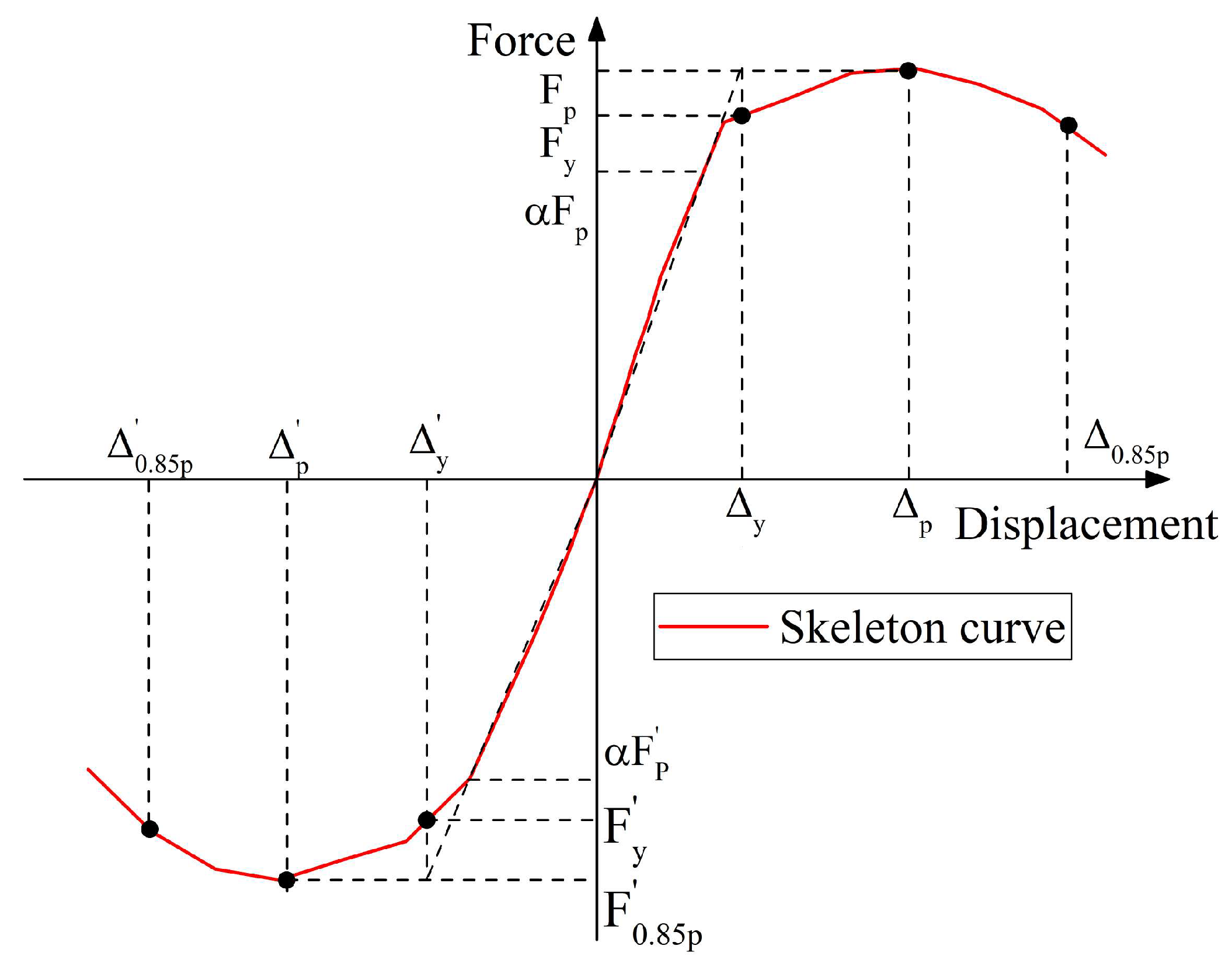
Figure 12.
Yielding displacement of PBCS walls.

Figure 13.
Ductility of PBCS walls.

Figure 14.
Cumulative dissipated energy of PBCS walls.


Table 1.
Specimen details.
| Specimen No. | SSR (H/L) | Bracing Type | Wall Dimension | Reinforcement Ratio (%) | Thickness Ratio of EPS Board | |
|---|---|---|---|---|---|---|
| (3) | ||||||
| DW1.0-5 | 1.0 | X | 1500 × 1500 × 150 | 0.84 Φ8@100 | 0.30 Φ6.5@150 | 0.33 |
| DW1.5-5 | 1.5 | X | 2250 × 1500 × 150 | |||
| DW2.0-5 | 2.0 | X | 3000 × 1500 × 150 | |||
| CW1.0-5 | 1.0 | + | 1500 × 1500 × 150 | |||
| CW1.5-5 | 1.5 | + | 2250 × 1500 × 150 | |||
| CW2.0-5 | 2.0 | + | 3000 × 1500 × 150 | |||
Note: X = diagonal bracing; + = cross bracing. = RR of concealed bracing; = RR of horizontal web reinforcement; = RR of vertical web reinforcement; Φ = hot-rolled plain steel bars.
Disclaimer/Publisher’s Note: The statements, opinions and data contained in all publications are solely those of the individual author(s) and contributor(s) and not of MDPI and/or the editor(s). MDPI and/or the editor(s) disclaim responsibility for any injury to people or property resulting from any ideas, methods, instructions or products referred to in the content. |
© 2023 by the authors. Licensee MDPI, Basel, Switzerland. This article is an open access article distributed under the terms and conditions of the Creative Commons Attribution (CC BY) license (https://creativecommons.org/licenses/by/4.0/).
Share and Cite
MDPI and ACS Style
Tang, Y.; Li, H. Effects of Embedded Expanded Polystyrene Boards on the Hysteretic Behavior of Innovative Precast Braced Concrete Shear Walls. Buildings 2024, 14, 55. https://doi.org/10.3390/buildings14010055
AMA Style
Tang Y, Li H. Effects of Embedded Expanded Polystyrene Boards on the Hysteretic Behavior of Innovative Precast Braced Concrete Shear Walls. Buildings. 2024; 14(1):55. https://doi.org/10.3390/buildings14010055
Chicago/Turabian StyleTang, Yachao, and Hongnan Li. 2024. "Effects of Embedded Expanded Polystyrene Boards on the Hysteretic Behavior of Innovative Precast Braced Concrete Shear Walls" Buildings 14, no. 1: 55. https://doi.org/10.3390/buildings14010055
Note that from the first issue of 2016, this journal uses article numbers instead of page numbers. See further details here.