
Research on the Performance of Lightweight Prefabricated Concrete Stairs with a Special-Shaped Hollow Landing Slab
School of Civil Engineering, Key Laboratory of Building Structural Retrofitting and Underground Space of Ministry of Education, Shandong Jianzhu University, Jinan 250101, China
*
Author to whom correspondence should be addressed.
Buildings 2024, 14(5), 1314; https://doi.org/10.3390/buildings14051314
Submission received: 18 March 2024
/
Revised: 22 April 2024
/
Accepted: 3 May 2024
/
Published: 7 May 2024
(This article belongs to the Section Building Structures)
Abstract
:In order to further improve the technical advantages of lightweight prefabricated concrete stairs, a kind of prefabricated stair system using a special-shaped hollow landing slab was proposed. Based on the detailed structural composition display, the design method for the main components (prefabricated flight and special-shaped prefabricated hollow landing slab) was proposed and a design application example was provided. Furthermore, specialized experimental and numerical simulation studies were conducted on the key component—the special-shaped prefabricated hollow landing slab. The research results indicated that this new kind of lightweight prefabricated concrete stairs using a special-shaped prefabricated hollow landing slab has reasonable construction, an effective design method, a clear force transmission mechanism, moderate component weight, and high transportation and installation convenience.
1. Introduction
Prefabricated concrete structural systems are currently one of the research hotspots in the field of structural engineering. In the overall structural system, stairs are indispensable and important components, and they have the characteristics of high standardization and suitability for prefabrication. Therefore, there have been many studies on prefabricated concrete stairs, such as static performance testing and evaluation [1,2,3], seismic performance analysis [4,5,6,7,8,9], connecting nodes of prefabricated stairs [10], construction technology research [11], analysis of prefabricated stair mold [12], etc.
Considering the transportation and lifting requirements of prefabricated components, an ideal prefabricated concrete staircase should have the characteristic of being easy to move. There are two corresponding technical ideas: one idea is to first divide and then assemble [13,14,15,16]; another idea is to develop lightweight prefabricated stairs, such as lightweight prefabricated stairs equipped with integrated lightweight staircase partition wall panels [17], lightweight prefabricated stairs using lightweight materials and steel wire mesh [18], lightweight prefabricated stairs using “double beam + thin slab” construction with weight-reducing cavities in the steps [19], and lightweight prefabricated stairs setting longitudinal continuous holes in the diagonal staircase [20]. By comparison, the technology concept of first slicing and then assembling has relatively high implementation difficulty, a relatively large on-site construction workload, and many unstable factors. Therefore, it is more recommended to adopt the concept of lightweight prefabricated stairs.
To further enrich the technical solutions and improve the technical and economic efficiency of lightweight prefabricated concrete stairs, a new type of lightweight prefabricated staircase system will be proposed in this paper. The design method and mechanical properties of this staircase system will be studied by combining numerical simulation and experiment, which can provide a technical basis for its engineering application.
2. Structural Composition and Design Method of the New Stair System
2.1. Structural Composition
Figure 1 shows the main construction of the new prefabricated stair system. The new stair system is mainly composed of prefabricated flights and special-shaped prefabricated hollow landing slabs. The special-shaped hollow platform slabs are used to support the prefabricated flights and are supported by platform support beams or floor beams.
Prefabricated flight: Including landing at both ends and serrated inclined slab. The surface and bottom of the serrated inclined slab are equipped with full-length longitudinal reinforcements and distributed reinforcements along the transversal direction. The step platforms contain reinforcement cages composed of longitudinal reinforcements and stirrups.
Special-shaped prefabricated hollow landing slab: Located at the floor or half-floor level position. It contains a reinforcement cage composed of longitudinal reinforcements and stirrups. Full-length hollows are set longitudinally, which are designed to reduce the weight. The construction is shown in Figure 2.
The upper end of the prefabricated flight should be set with fixed hinge support and the lower end should be set with sliding hinge support. The rotational and sliding deformation capacity of the support should meet the requirements for the inter-story displacement of the structure shown in the GB 50010-2010 Concrete structure design code [21]. The detailed construction can be determined by referring to the 15G310-1-2 Assembled Concrete Connection Node Structure Collection [22].
Platform support beams can be supported by the vertical load-bearing components (columns) of the structure and are surrounded by the non-load-bearing wall of the stairwell. Floor beams are usually frame beams or ring beams of the structure.
2.2. Design Method
2.2.1. Design of Prefabricated Flight
Two types of loads need to be considered: constant load (self-weight) and live load (according to the GB50009-2012 Load code for the design of building structures [23], the standard value can be taken as 3.5 kN/m2). The constant load and live load should be multiplied by the partial safety factor 1.3 and 1.5 to obtain the design value, respectively [24]. Then, the initial dimensions can be selected and a calculation model can be established based on the oblique simply supported beam, considering the fixed effects at both ends. After obtaining the most unfavorable internal forces, reinforcement design can be carried out.
2.2.2. Design of Special-Shaped Prefabricated Hollow Landing Slab
Three types of loads need to be considered. (1) Self-load (including constant load and live load): the constant load is the self-weight, which should be multiplied by 1.3 to obtain the design value. The design value of the live load can also be taken as 3.5 kN/m2 multiplied by 1.5 [24]. The range of action is the top surface of the special-shaped prefabricated hollow landing slab. (2) The load transmitted from the prefabricated flight, which acts on the upper surface of the connection with the prefabricated flight. This load can be applied to the corresponding position (downwards) in the form of a vertically uniformly distributed load, with a magnitude equal to the support reaction force of the prefabricated flight. (3) The load transmitted from the non-load-bearing wall of the stairwell, which acts on the upper surface of the support at both ends of the special-shaped prefabricated hollow landing slab in the form of a vertically distributed load (downward). The value is determined by the bulk density of the upper wall material.
Due to the special shape of the hollow landing slab, it is difficult to directly establish a calculation model and obtain internal forces. To this end, it is recommended that finite element software be used for the numerical simulation of the concrete part, firstly to obtain the stress conditions under the designed load, and then so that the reinforcement design can be carried out based on the stress distribution results and related specifications (GB 50010-2010 Concrete structure design code [21]; JGJ1-2014 Technical specification for prefabricated concrete structure [25]).
3. Design Example of the New Stair System
According to the structural composition of the new stair system, the design method and static performance of the representative load-bearing components (prefabricated flight and the special-shaped prefabricated hollow landing slab) will be analyzed in depth by combining an example.
3.1. Basic Parameters of the Representative Load-Bearing Components
Prefabricated Flight
The width of the prefabricated flight is 1200 mm. Figure 3 shows the specific dimensions of the prefabricated flight.
The specific dimensions of the special-shaped prefabricated hollow landing slab are shown in Figure 4.
The grade of the concrete is selected as C30.
3.2. Design and Analysis of Prefabricated Flight
3.2.1. Design Value of Load and Internal Force
After calculating the design values of the dead load and live load, respectively, the design load value of the prefabricated flight can be determined as 14.48 kN/m. Considering the fixed effect at both ends, the maximum bending moment on the prefabricated flight can be obtained as 15.11 kN·m, which is in the mid-span position.
3.2.2. Reinforcement Scheme
The thickness of the protective layer is 15 mm. h and b are the thickness and section width of the serrated inclined slab, with a value of 120 mm and 1200 mm, respectively. as’ is 20 mm. h0 is the effective section height, with a value of 100 mm.
According to the reinforcement method of ordinary reinforced concrete bending components, the reinforcement arrangement scheme is shown in Figure 5.
3.3. Design and Analysis of Special-Shaped Prefabricated Hollow Landing Slab
3.3.1. Load
The constant load is multiplied by the partial safety factor 1.3 to obtain the design value. The design value of the live load is 5.25 kN/m2, which applies on the top surface of the prefabricated hollow landing slab (orange area in Figure 6).
The load transmitted from the prefabricated flight acts downward on the top surface where the prefabricated flight is supported (red area in Figure 6) in the form of a vertical uniform load. The value is equal to the support reaction force of the prefabricated flight, which is 114.605 kN/m2.
The load transmitted from the walls of the stairwell acts downward on the top surface of the two ends of the prefabricated hollow landing slab (blue area in Figure 6) in the form of a vertical uniform load. The wall material is selected as an aerated concrete block with a unit weight of 600 kg/m3. The value of this kind of load can be determined as 15.994 kN/m2.
3.3.2. Analysis of Plain Concrete Model and Determination of Reinforcement Scheme
The plain concrete model of the prefabricated hollow landing slab was established according to the dimensions. The element type and material characteristics are identical to the prefabricated flight model. The two ends of the special-shaped prefabricated hollow landing slab are fixed. Figure 6 shows the loads and boundary conditions.
The longitudinal stress, transverse stress and vertical stress were analyzed. The focus of the analysis was on the mid-span section and the section near the support of the prefabricated hollow landing slab along the longitudinal direction, which are representative sections of the stress situation.
- (1)
- Longitudinal stress analysis
- (i)
- Mid-span section (Figure 7a):
The elements in the area below the center of the hollow part are mainly subjected to longitudinal tensile stress, with a maximum value of 0.603 MPa. The other elements are subjected to longitudinal compressive stress, with a maximum value of 1.467 MPa.
- (ii)
- End section (Figure 7b):
The elements in the bottom area are mainly subjected to longitudinal compressive stress, with a maximum value of 2.120 MPa. The other elements are subjected to longitudinal tensile stress, with a maximum value of 2.027 MPa.
- (2)
- Transverse stress analysis
- (i)
- Mid-span section (Figure 8a):
The elements in the bottom area are mainly subjected to transverse compressive stress, and the elements in the upper right area and lower left area of the circular hollows are also subjected to transverse compressive stress, with a maximum value of 0.375 MPa. The other elements are subjected to transverse tensile stress, with a maximum value of 0.305 MPa.
- (ii)
- End section (Figure 8b):
The elements in the bottom area are mainly subjected to transverse tensile stress, and the elements in the upper left area and lower right area of the circular hollows are also subjected to transverse tensile stress, with a maximum value of 0.440 MPa. The other elements are subjected to transverse compressive stress, with a maximum value of 0.687 MPa.
- (3)
- Vertical stress analysis
- (i)
- Mid-span section (Figure 9a):
The elements in the area near the corner are subjected to vertical tensile stress, and the elements in the upper left area and lower right area of the circular hollows are also subjected to vertical tensile stress, with a maximum value of 0.534 MPa. The other elements are subjected to vertical compressive stress, with a maximum value of 0.389 MPa.
- (ii)
- End section (Figure 9b):
The elements in the bottom area are mainly subjected to vertical compressive stress, and the elements in the upper left area and lower right area of the circular hollows are also subjected to vertical compressive stress, with a maximum value of 1.506 MPa. The other elements are subjected to vertical tensile stress, with a maximum value of 0.285 MPa.
Based on the stress analysis results of the three directions and the construction requirements, the reinforcement arrangement of the special-shaped prefabricated hollow landing slab can be carried out as described below:
The environmental category is selected as class 1. The protective layer thickness of the special-shaped prefabricated hollow landing slab is selected as 15 mm.
- (1)
- Reinforcements arrangement according to longitudinal stress
According to the stress results, all the stress does not exceed the standard value of concrete strength. Therefore, the reinforcements arrangement can be determined directly according to the construction requirements.
According to the construction requirements, the unilateral reinforcement of the special-shaped prefabricated hollow landing slab should meet the minimum reinforcement area. After calculation, the unilateral minimum reinforcement area is 318.52 mm2. Therefore, the longitudinal reinforcements on the top side can be selected as 6![Buildings 14 01314 i001]() 10HRB400 and the sectional area of the reinforcements as 471 mm2. The longitudinal reinforcements on the bottom side can be selected as 7
10HRB400 and the sectional area of the reinforcements as 471 mm2. The longitudinal reinforcements on the bottom side can be selected as 7![Buildings 14 01314 i001]() 10HRB400 and the sectional area of the reinforcements as 550 mm2. According to the stress distribution and construction requirements, 2
10HRB400 and the sectional area of the reinforcements as 550 mm2. According to the stress distribution and construction requirements, 2![Buildings 14 01314 i001]() 10HRB400 longitudinal reinforcements should be arranged 44 mm above the two reinforcements at the bottom left end. All the longitudinal reinforcements should be equipped with 135° hooks at both ends, with a hook length of 50 mm.
10HRB400 longitudinal reinforcements should be arranged 44 mm above the two reinforcements at the bottom left end. All the longitudinal reinforcements should be equipped with 135° hooks at both ends, with a hook length of 50 mm.
 10HRB400 and the sectional area of the reinforcements as 471 mm2. The longitudinal reinforcements on the bottom side can be selected as 710HRB400 and the sectional area of the reinforcements as 550 mm2. According to the stress distribution and construction requirements, 210HRB400 longitudinal reinforcements should be arranged 44 mm above the two reinforcements at the bottom left end. All the longitudinal reinforcements should be equipped with 135° hooks at both ends, with a hook length of 50 mm.
- (2)
- Reinforcements arrangement according to transverse stress
According to the transverse stress results, all the stress does not exceed the standard value of concrete strength. Therefore, the reinforcement arrangement can be determined directly according to the construction requirements.
Stirrups, ![Buildings 14 01314 i001]() 8@200, are arranged around the top longitudinal reinforcements and bottom longitudinal reinforcements of the prefabricated hollow landing slab. Stirrups,
8@200, are arranged around the top longitudinal reinforcements and bottom longitudinal reinforcements of the prefabricated hollow landing slab. Stirrups, ![Buildings 14 01314 i001]() 8@200, are arranged around the top longitudinal reinforcements and bottom longitudinal reinforcements of the left protruding part.
8@200, are arranged around the top longitudinal reinforcements and bottom longitudinal reinforcements of the left protruding part.
8@200, are arranged around the top longitudinal reinforcements and bottom longitudinal reinforcements of the prefabricated hollow landing slab. Stirrups, 8@200, are arranged around the top longitudinal reinforcements and bottom longitudinal reinforcements of the left protruding part.The complete reinforcements arrangement of the special-shaped prefabricated hollow landing slab is shown in Figure 10.
3.3.3. ABAQUS Modeling of the Whole Special-Shaped Prefabricated Hollow Landing Slab
Models of the reinforcements were established according to the dimensions and built into the plain concrete model by way of the embedded region. Figure 11 shows the integrated model of the special-shaped prefabricated hollow landing slab.
The stress of the special-shaped prefabricated hollow landing slab can then be obtained, which is shown in Figure 12.
- (1)
- Concrete:
The maximum tensile and compressive stress in each direction is shown in Table 1.
According to Table 1, the stress in each direction does not exceed the tensile and compressive strength of concrete. In addition, the value of the maximum principal stress is 2.003 MPa, which is located at the bottom of the hollow area at the supports at both ends. It can be seen that the maximum principal stress also does not exceed the tensile strength of the concrete.
- (2)
- Reinforcements:
The maximum tensile stress is 11.85 MPa, which does not exceed the tensile strength of the reinforcements.
Deformation of the special-shaped prefabricated hollow landing slab can also be obtained, as shown in Figure 13.
The maximum horizontal and longitudinal deformation is 0.036 mm and 0.041 mm, respectively. The maximum vertical deformation is 0.250 mm < [f]2 = l2/200 = 12.6 mm, where [f]2 is the deflection limit of the special-shaped prefabricated hollow landing slab and l2 is the calculation span of the special-shaped prefabricated hollow landing slab.
4. Further Study on the Special-Shaped Prefabricated Hollow Landing Slab by Test and Simulation
The special-shaped prefabricated hollow landing slab plays an important role in bearing the loads transmitted from the prefabricated flights and walls and transferring the loads to the vertical load-bearing components. Therefore, the static load test was carried out to further study the static performance of the special-shaped prefabricated hollow landing slab by scale model in this section. The strain and deformation under different loads were studied. The test results were compared and verified with the numerical simulation results to provide a further technical basis for the theoretical analysis and engineering design of the special-shaped prefabricated hollow landing slab.
4.1. Specimen Design and Fabrication
4.1.1. Scale Design
The design principles of the scale model in the static test include the geometric similarity principle, physical condition similarity principle and boundary condition similarity principle. The length of each side of the scale specimen is selected as 1/2 of that of the full-scale model. The material used in the specimen is the same as that used in the full-size model. The similarity constant ratios of each physical parameter are shown in Table 2.
4.1.2. Specimen Design
A specimen was designed with the concrete grade set as C30. The dimensions are shown in Figure 14.
The mix proportions of the concrete used in this test are shown in Table 3.
After 28 d curing, the average value of compressive strength is 39.03 MPa. The density is 2392 kg/m3.
The design value of the constant load is the self-weight multiplied by 1.3. The design value of the live load is 3.5 kN/m2 multiplied by 1.5, which acts on the top surface of the specimen. The load transmitted from the prefabricated flight acts downward on the top surface, with the value as 82.100 kN/m2. The load transmitted from the walls of the stairwell acts downward on the top surface of specimen, with the value as 8.997 kN/m2.
ABAQUS is used for the numerical simulation of the concrete part to obtain the stress conditions, and then the reinforcement scheme can be determined based on the stress distribution results and related specifications [21,24].
The reinforcements arrangement of the specimen is shown in Figure 15.
The finished specimen is shown in Figure 16.
4.1.3. Layout of Measuring Points
BF120-50AA strain gauges were used to measure the strain of the specimen. Three strain gauges (C1, C2, C3) were pasted on the top surface of the specimen along the longitudinal direction at the mid-span. The positions of the strain gauges are shown in Figure 17a, and the distance between the strain gauges is 150 mm. Three strain gauges (C4, C5, C6) were pasted on the bottom surface of the specimen along the longitudinal direction at the mid-span. The positions of the strain gauges are shown in Figure 17b, and the distance between the strain gauges is 150 mm. In addition, two strain gauges (C7, C8) were pasted on the front surface at the two ends of the support of the specimen.
YHD-50 displacement transducers were used to measure the displacement of the specimen. Three displacement transducers (W1, W2, W3) were set on the bottom surface of the specimen along the longitudinal direction at the mid-span. The positions of the displacement transducers are shown in Figure 18, and the distance between the displacement transducers is 150 mm.
The DH3818N-2 static data acquisition system was utilized.
4.2. Loading and Results
4.2.1. Loading
The purpose of this test is to investigate the strain and deformation of the specimen under load. The load is applied by steel loading blocks and sandbags. Each steel loading block is 20 kg and the dimensions are 210 mm × 150 mm × 130 mm. The weight of the sandbag can be adjusted as needed. The loading process should be slow and uniform.
The specimen was loaded in two areas: area 1 (top surface) and area 2 (where the prefabricated flights are supported). The uniform load in loading area 1 included the live load and the load transmitted from the walls at both ends (remained unchanged throughout the loading process). The uniform load in loading area 2 was difficult to apply directly. Therefore, horizontal steel pipes were used for the auxiliary loading, as shown in Figure 19: one end of the steel pipes was supported on the specimen and the other end was supported on the concrete blocks. The loading blocks and sandbags were stacked on the steel pipes for loading. Planks were laid between the steel pipes and the specimen, transforming the support reaction into a uniform load.
According to the different loading areas, the loading process for this test was divided into two stages, both of which were graded loading. In stage 1, area 1 and area 2 were simultaneously loaded. The load in area 1 was the live load of different grades. The load in area 2 was the load transmitted from the prefabricated flight under different grades of live load. Table 4 shows the loading regime of stage 1, where load 6 represents the design value of the load.
In stage 2, the load of area 2 remained unchanged. The live load of area 1 continued to increase with each grade of 0.81 kN/m2 until it reached 15.78 kN/m2 (approximately three times the design value). The corresponding loading grade is marked as ‘load 19’.
The strain and displacement of the specimen under different load grades were obtained.
4.2.2. Test Results and Analysis
- (1)
- Loading stage 1
The strain and displacement are shown in Figure 20.
- (2)
- Loading stage 2
The strain and displacement are shown in Figure 21.
- (3)
- Analysis
The strain of the first three strain gauges (C1, C2, C3) is compressive strain, while the strain of the other gauges (C4–C8) is tensile strain.
In most cases, the strain values of each strain gauge are constantly increasing as the load grade increases. In a few cases, due to the influence of the loading error and data acquisition error, the values of some strain gauges do not increase completely with the increase in the loading values (for example, the strain of C7 and C8 in stage 2).
When the live load of area 1 and 2 reaches the design value (Load 6), the maximum compressive strain and maximum tensile strain of the specimen are 40.624 × 10⁻⁶ and 17.972 × 10⁻⁶, respectively. The corresponding maximum compressive stress and maximum tensile stress of the specimen are 1.219 MPa and 0.539 MPa, respectively. It can be seen that the maximum compressive stress and maximum tensile stress do not exceed the compressive and tensile strength of concrete. No cracks are observed. Continuing to load, when the live load of area 1 reaches 15.78 kN/m2 (approximately three times the design value), the maximum compressive strain and maximum tensile strain of the specimen are 53.302 × 10⁻⁶ and 25.539 × 10⁻⁶, respectively. The corresponding maximum compressive stress and maximum tensile stress of the specimen are 1.599 MPa and 0.766 MPa, respectively. It can be seen that the maximum compressive stress and maximum tensile stress do not exceed the compressive and tensile strength of concrete. No cracks are observed.
For the vertical displacement results, when the live load of area 1 and 2 reaches the design value (Load 6), the maximum vertical displacement of the specimen is 0.1 mm < [f]3 = l3/200 = 6.9 mm, where [f]3 is the deflection limit of the prefabricated hollow landing slab scale model and l3 is the calculation span of the prefabricated hollow landing slab scale model. Therefore, the deformation of the specimen meets the requirements. Continuing to load, the maximum vertical displacement of the specimen is 0.110 mm when the live load of area 1 reaches 15.78 kN/m2 (approximately three times the design value), which still meets the deformation requirements. The results indicate that the special-shaped prefabricated hollow landing slab has sufficient bending stiffness.
4.3. ABAQUS Modeling and Comparison of Results with Test Results
According to the reinforcement scheme of the specimen, the integrated ABAQUS model of specimen can be obtained as in Figure 22.
Subsequently, the stress and deformation results of the ABAQUS model under various loading grades can be obtained. Comparative analysis with the test can then be carried out.
- (1)
- Loading stage 1
- (i)
- Strain comparison of C1–C3
The comparison between the simulation and the test results of C1, C2 and C3 is shown in Figure 23.
- (ii)
- Strain comparison of C4–C6
The comparison between the simulation and the test results of C4, C5 and C6 is shown in Figure 24.
- (iii)
- Strain comparison of C7–C8
The comparison between the simulation and the test results of C7 and C8 is shown in Figure 25.
- (iv)
- Displacement comparison
The comparison between the simulation and the test results of W1, W2 and W3 is shown in Figure 26.
- (2)
- Loading stage 2
- (i)
- Strain comparison of C1–C3
The comparison between the simulation and the test results of C1, C2 and C3 is shown in Figure 27.
- (ii)
- Strain comparison of C4–C6
The comparison between the simulation and the test results of C4, C5 and C6 is shown in Figure 28.
- (iii)
- Strain comparison of C7–C8
The comparison between the simulation and the test results of C7 and C8 is shown in Figure 29.
- (iv)
- Displacement comparison
The comparison between the simulation and the test results of W1, W2 and W3 is shown in Figure 30.
4.4. Analysis of Comparison Results
The comparison results reveal the following:
- (1)
- In most cases, the results variation trend of the strain and vertical displacement in the test is roughly the same as that of the simulation results.
- (2)
- In a few cases, the results variation trend in the numerical simulation is more accurate than the results variation trend in the test (for example, the strain of C7 and C8 in stage 2) because numerical simulation can avoid the influence of errors in the actual loading and data acquisition process.
- (3)
- As a whole, the error between the test results and the simulation results is usually not more than 13% (most of them are less than 10%). This kind of small range of numerical fluctuations is acceptable.
- (4)
- Numerical simulation based on ABAQUS is an effective means of studying the mechanical performance of the special-shaped prefabricated hollow landing slab.
- (5)
- Based on the results of the test and numerical simulation, the design method for the special-shaped prefabricated hollow landing slab can be proven to be feasible and reasonable.
5. Conclusions
In this paper, a new type of prefabricated lightweight concrete stair system was proposed. Based on clarifying the specific structural composition, the design method was provided and verified through an example. Experiment and numerical simulation studies were carried out to further explore the mechanical performance of the key component. The systematic study reveals the following:
- (1)
- The stair system with a special-shaped prefabricated hollow landing slab as the key component, supplemented by prefabricated flight and support beams (platform support beam and floor beam), is a new and effective type of lightweight concrete stair system.
- (2)
- The new type of lightweight stair system has a clear transmission mechanism and can easily obtain internal force and stress situations. For the prefabricated flight and support beams, they can be designed directly according to the internal force situation as reinforced concrete bending components. For the special-shaped prefabricated hollow landing slab, it is recommended to adopt numerical simulation to obtain the stress situation of the concrete part under the design load, and then to combine the construction requirements to complete the reinforcement design.
- (3)
- The new type of lightweight stair system has a high degree of standardization, moderate weight and volume, and low transportation requirements, which suggest broad application prospects.
Author Contributions
Conceptualization, Y.W. (Yilin Wang) and D.S.; methodology, Y.W. (Yilin Wang) and D.S.; software, D.S.; validation, Y.W. (Yilin Wang) and D.S. and Y.W.; formal analysis, Y.W. and D.S.; investigation, D.S.; resources, Y.W.; data curation, D.S. and Y.W.; writing—original draft preparation, D.S.; writing—review and editing, Y.W.; visualization, D.S.; supervision, Y.W.; project administration, Y.W. (Yilin Wang); funding acquisition, Y.W. (Yilin Wang). All authors have read and agreed to the published version of the manuscript.
Funding
This work was funded by the National Natural Science Foundation of China under grant number 51608311 and the Program for Changjiang Scholars and Innovative Research Team in University of China under grant number IRT13075.
Data Availability Statement
Data are contained within the article.
Acknowledgments
The authors wish to express their appreciation and gratitude to the anonymous reviewers and editors for their insightful comments and suggestions for improving the paper’s quality.
Conflicts of Interest
The authors declare no conflicts of interest.
References
- Pěnčík, J.; Lavický, M.; Kral, P.; Havířová, Z. Analysis of Behaviour of Prefabricated Staircases with One-Sided Suspended Stairs. Drv. Ind. 2015, 66, 147–156. [Google Scholar] [CrossRef]
- Liu, W.Z.; Cui, S.Q. Experimental study on the flexural performance of prefabricated prestressed concrete stairs. Build. Struct. 2021, 51, 8–15. (In Chinese) [Google Scholar] [CrossRef]
- Wang, Y.L.; Sheng, D.P.; Wang, S.Y.; Wen, J.Q. Development and performance research of a new stair system for prefabricated concrete structures. Sichuan Build. Sci. 2023, 49, 31–39. (In Chinese) [Google Scholar] [CrossRef]
- Qin, L. Shaking Table Test and Finite Element Analysis of Sliding Prefabricated Stairs. Master’s Thesis, Chongqing University, Chongqing, China, 2021. (In Chinese). [Google Scholar] [CrossRef]
- Zhang, C.; Ding, C.; Zhou, Y.; Wang, G.; Shi, F.; Huang, W. Seismic behavior of prefabricated reinforced concrete stair isolated by high damping rubber bearings. Bull. Earthq. Eng. 2022, 21, 1325–1352. [Google Scholar] [CrossRef]
- Wang, G.Y. Research on Seismic Performance of Prefabricated Energy Dissipation and Shock-Absorbing Staircase Units. Master’s Thesis, Guangzhou University, Guangzhou, China, 2020. (In Chinese). [Google Scholar]
- Botsa, S.R. Dasgupta K. Influence of staircase and elevator core location on the seismic capacity of an RC frame building. J. Archit. Eng. 2017, 23, 05017007. [Google Scholar] [CrossRef]
- Cong, S.; Zhang, Z.; Zheng, Q.; Xu, Z. Seismic behavior of reinforced concrete frame staircase with separated slab stairs. Structures 2021, 34, 4284–4296. [Google Scholar] [CrossRef]
- Zhang, Y.; Tan, P.; Ma, H.T.; Donà, M. Improving the Seismic Performance of Staircases in Building Structures with a Novel Isolator. Comput. Model. Eng. Sci. 2020, 124, 415–431. [Google Scholar] [CrossRef]
- Zhang, S.F.; Huo, W.Y.; Liu, K.; Yao, Y.; Sun, Q. Experimental Study on the New Type of Connecting Nodes of Prefabricated Stairs Using Flexible Grouting Material. J. Phys. Conf. Ser. 2023, 2553, 012021. [Google Scholar] [CrossRef]
- Xiao, Y.W. Analysis of Key Construction Techniques for Prefabricated Stairs in Building Engineering. Sichuan Cement. 2024, 1, 173–175. (In Chinese) [Google Scholar]
- Meng, L.H. Numerical Simulation of a Prefabricated Stair Mold Under Fluid Pressure. J. Phys. Conf. Ser. 2023, 2542, 012011. [Google Scholar] [CrossRef]
- Hu, H.; Li, Z.L.; Liu, H.J.; Jiang, Q.B. Experimental study and finite element analysis on sliced prefabricated staircases. Build. Struct. 2018, 48, 97–106. (In Chinese) [Google Scholar] [CrossRef]
- Wang, G.P. Study on preparation and performance of assembled prefabricated stairs. China Build. Mater. Technol. 2023, 32, 66–69. (In Chinese) [Google Scholar]
- Chen, G.; Pang, D.J.; Xie, W.Y. Construction Technology for Segmental Prefabricated Stair. Chongqing Archit. 2019, 18, 58–60. (In Chinese) [Google Scholar] [CrossRef]
- Zhou, S. Analysis on lightweight and hoisting optimization of prefabricated stairs. Eng. Technol. Res. 2023, 8, 126–128. (In Chinese) [Google Scholar] [CrossRef]
- You, R.H. Application of lightweight prefabricated staircase system. Sichuan Archit. 2022, 42, 73–75. (In Chinese) [Google Scholar] [CrossRef]
- Lei, Q.; Sun, T.T.; Shi, Y.; Wang, L. A new light-weight prefabricated staircase. Build. Technol. Dev. 2020, 47, 25–27. (In Chinese) [Google Scholar] [CrossRef]
- Li, N.; Xu, Q.G.; Huang, L.P.; Wei, S. Research on type selection and static loading test of lightweight assembled stairs. Eng. Construct. Design 2021, 15, 16–18+40. (In Chinese) [Google Scholar] [CrossRef]
- Song, S.F. Response Analysis of a New Prefabricated Hollow Slab Staircase under Seismic Action. Master’s Thesis, Harbin Institute of Technology, Harbin, China, 2014. (In Chinese). [Google Scholar]
- Ministry of Housing and Urban-Rural Development (MOHURD). GB 50010-2010 Code for Design of Concrete Structures; China Architecture Publishing & Media Co. Ltd.: Beijing, China, 2010. (In Chinese)
- China Building Standards Design and Research Institute. 15G310-1~2 Prefabricated Concrete Joint Structure Collection; China Planning Press: Beijing, China, 2015. (In Chinese)
- Ministry of Housing and Urban-Rural Development (MOHURD). GB50009-2012 Load Code for the Design of Building Structures; China Architecture Publishing & Media Co. Ltd.: Beijing, China, 2012. (In Chinese)
- Ministry of Housing and Urban-Rural Development (MOHURD). GB 55001-2021 General Specification for Engineering Structures; China Architecture Publishing & Media Co. Ltd.: Beijing, China, 2021. (In Chinese)
- Ministry of Housing and Urban-Rural Development (MOHURD). JGJ 1-2014 Technical Specification for Prefabricated Concrete Structure; China Architecture Publishing & Media Co. Ltd.: Beijing, China, 2014. (In Chinese)
Figure 1.
Structural composition of the new stair system.

Figure 2.
Special-shaped prefabricated hollow landing slab.

Figure 3.
Dimensions of the prefabricated flight.

Figure 4.
Dimensions of the special-shaped prefabricated hollow landing slab.
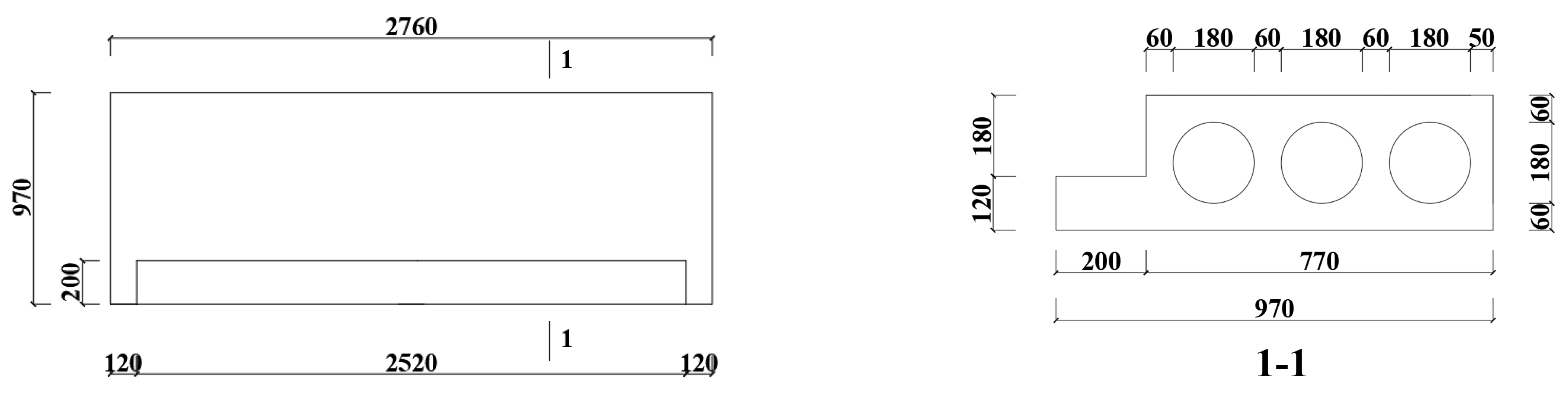
Figure 5.
Reinforcements arrangement of the prefabricated flight.


Figure 6.
Loads and boundary conditions.

Figure 7.
Longitudinal stress: (a) mid-span section and (b) section near the support.

Figure 8.
Transverse stress: (a) mid-span section, and (b) section near the support.

Figure 9.
Vertical stress: (a) mid-span section, and (b) section near the support.
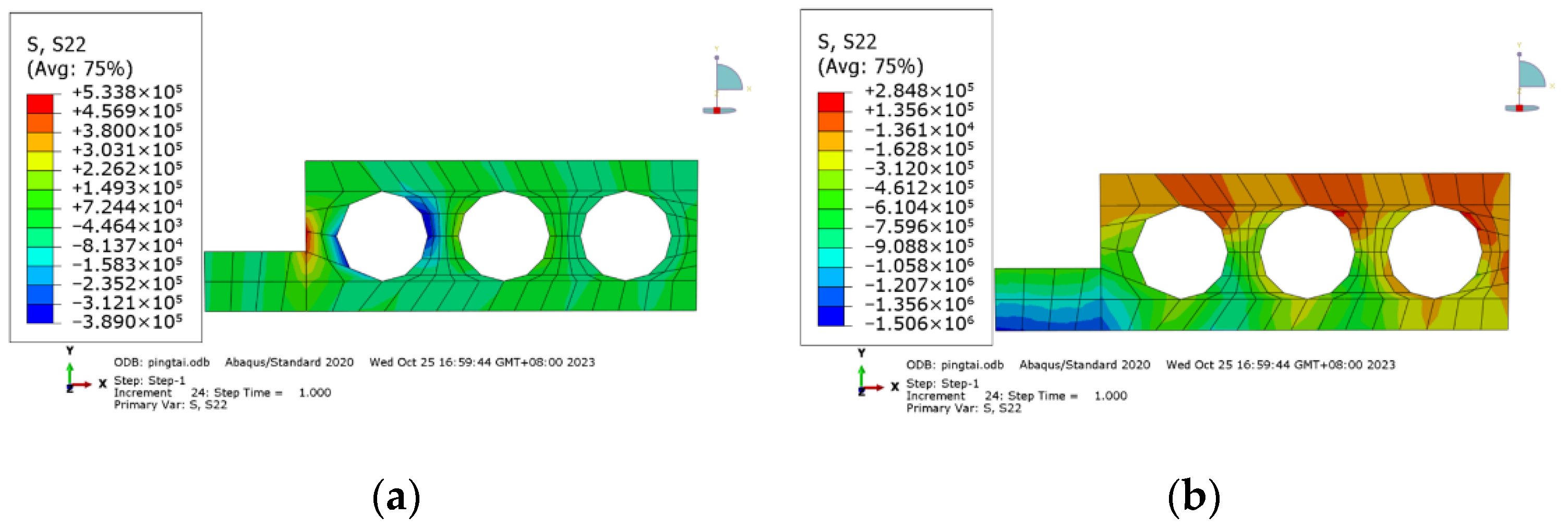
Figure 10.
Reinforcements of the special-shaped prefabricated hollow landing slab.

Figure 11.
Integrated model of the special-shaped prefabricated hollow landing slab.

Figure 12.
Stress of the special-shaped prefabricated hollow landing slab: (a) concrete stress, and (b) reinforcement stress.
Figure 12.
Stress of the special-shaped prefabricated hollow landing slab: (a) concrete stress, and (b) reinforcement stress.
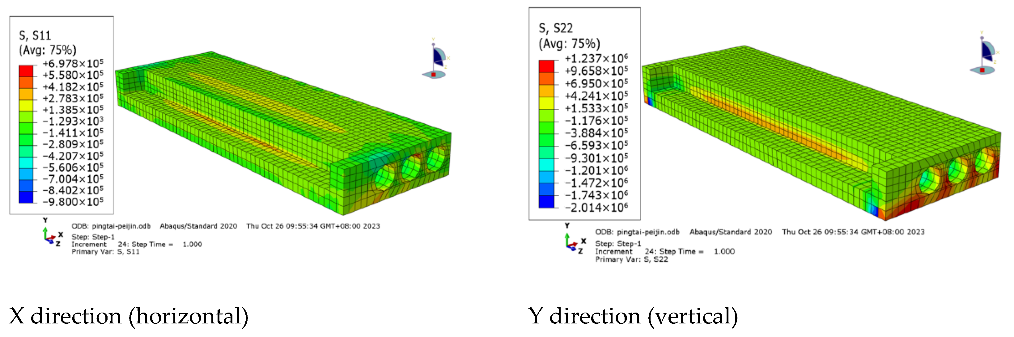
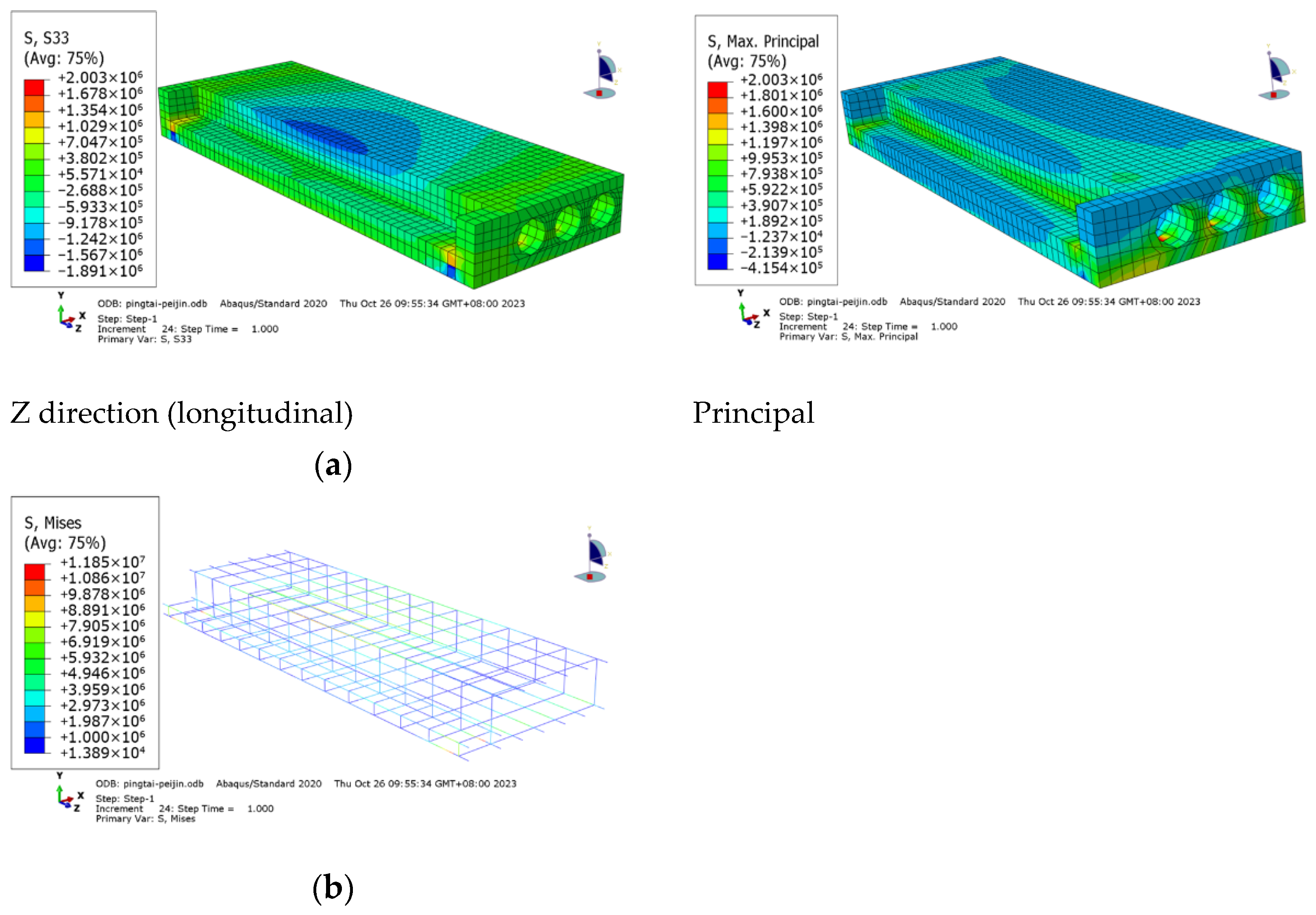
Figure 13.
Deformation of the special-shaped prefabricated hollow landing slab.

Figure 14.
Dimensions of the special-shaped prefabricated hollow landing slab specimen.

Figure 15.
Reinforcements of the specimen.

Figure 16.
Finished specimen.
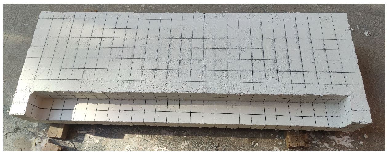
Figure 17.
Positions of the strain gauges.

Figure 18.
Positions of the displacement transducers.

Figure 19.
Loading.

Figure 20.
Strain and displacement in loading stage 1. (a) Strain of C1, C2 and C3 in stage 1, (b) strain of C4, C5 and C6 in stage 1, (c) strain of C7 and C8 in stage 1, and (d) displacement of W1, W2 and W3 in stage 1.
Figure 20.
Strain and displacement in loading stage 1. (a) Strain of C1, C2 and C3 in stage 1, (b) strain of C4, C5 and C6 in stage 1, (c) strain of C7 and C8 in stage 1, and (d) displacement of W1, W2 and W3 in stage 1.

Figure 21.
Strain and displacement in loading stage 2. (a) Strain of C1, C2 and C3 in stage 2, (b) strain of C4, C5 and C6 in stage 2, (c) strain of C7 and C8 in stage 2, and (d) displacement of W1, W2 and W3 in stage 2.
Figure 21.
Strain and displacement in loading stage 2. (a) Strain of C1, C2 and C3 in stage 2, (b) strain of C4, C5 and C6 in stage 2, (c) strain of C7 and C8 in stage 2, and (d) displacement of W1, W2 and W3 in stage 2.
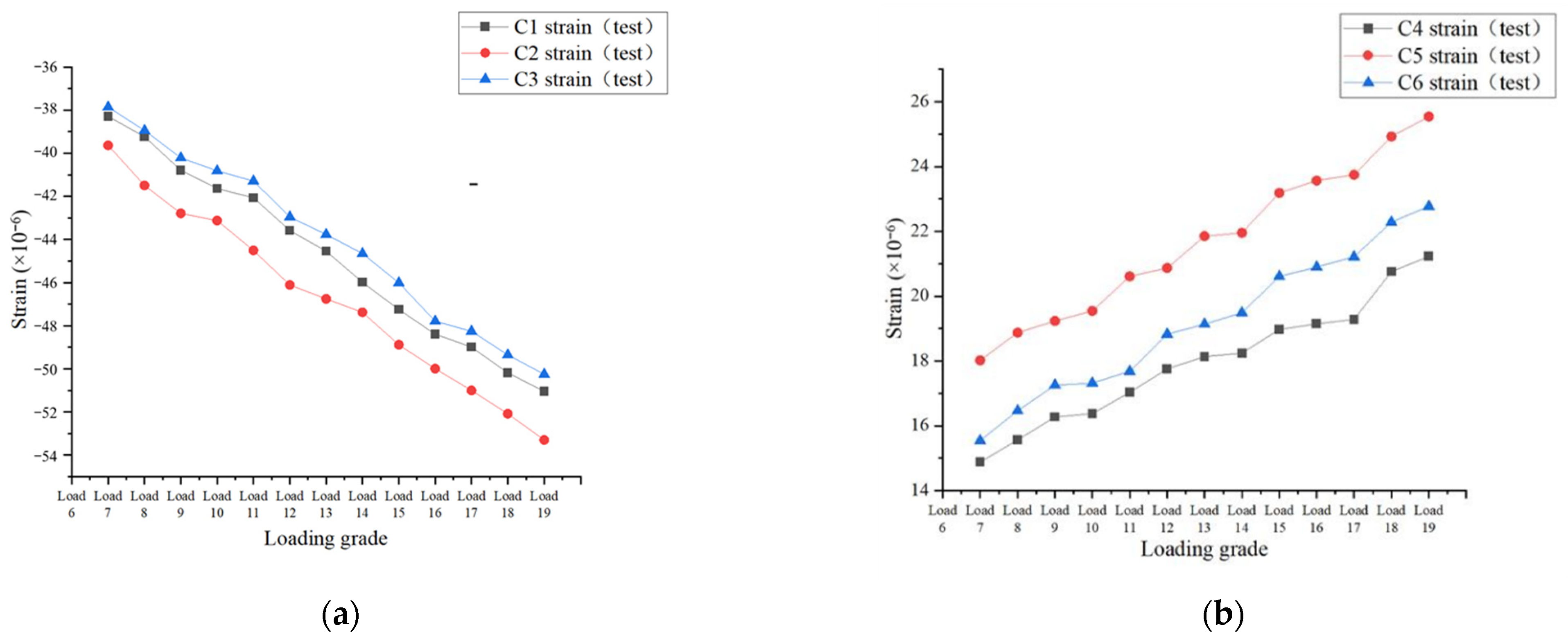
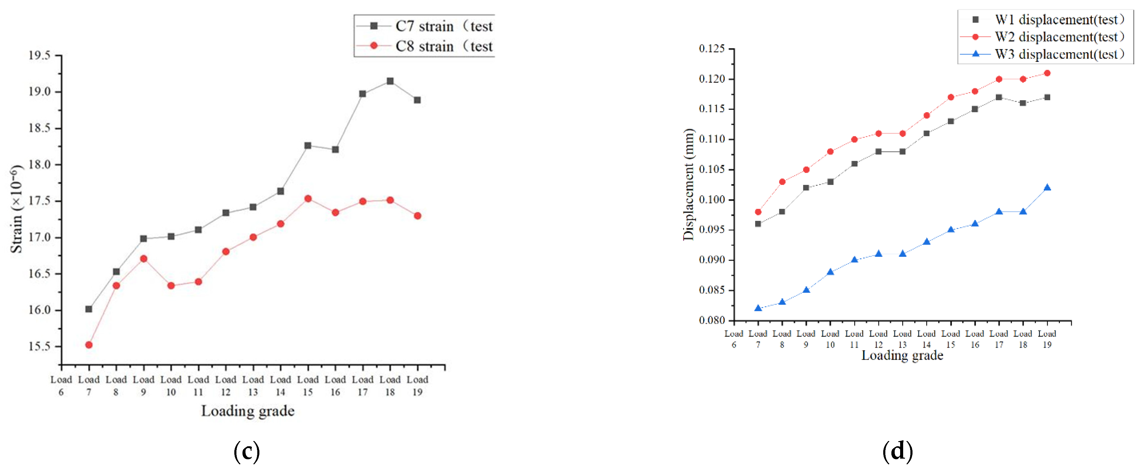
Figure 22.
Integrated ABAQUS model of the specimen.

Figure 23.
Comparison between the simulation and test results of C1, C2 and C3.

Figure 24.
Comparison between the simulation and the test results of C4, C5 and C6.

Figure 25.
Comparison between the simulation and the test results of C7 and C8.

Figure 26.
Comparison between the simulation and the test results of W1, W2 and W3.
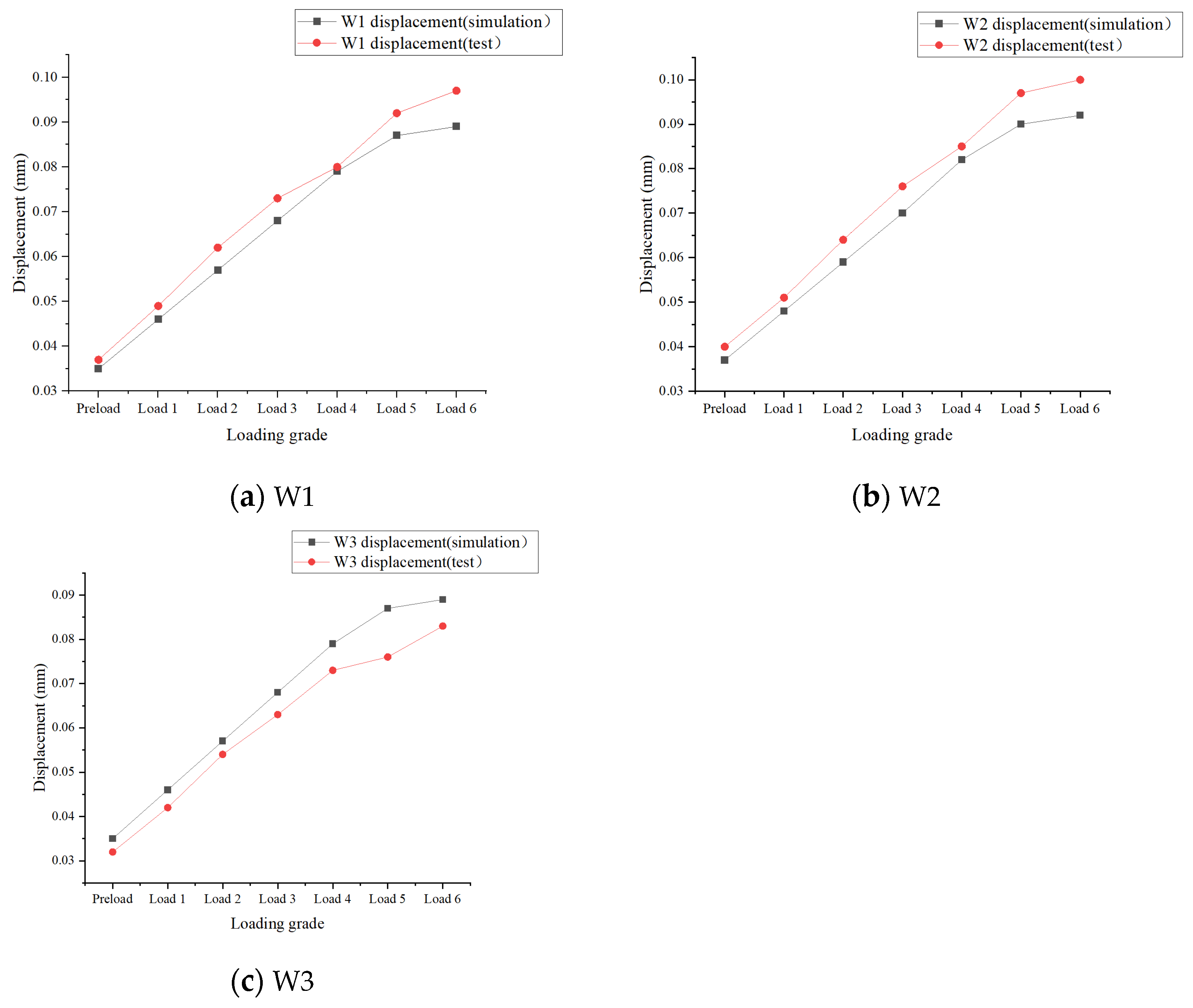
Figure 27.
Comparison between the simulation and the test results of C1, C2 and C3.


Figure 28.
Comparison between the simulation and the test results of C4, C5 and C6.
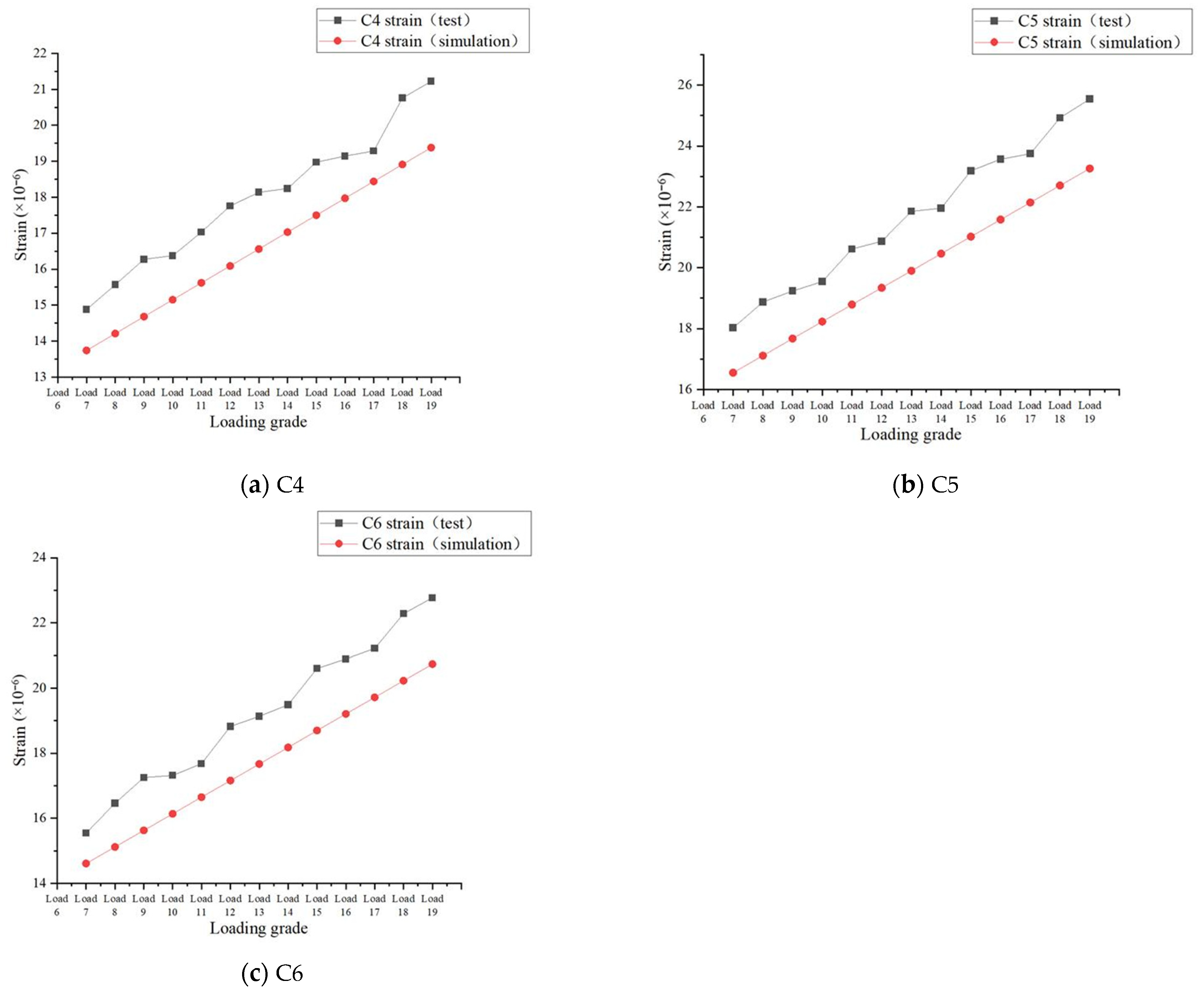
Figure 29.
Comparison between the simulation and the test results of C7 and C8.

Figure 30.
Comparison between the simulation and the test results of W1, W2 and W3.


Table 1.
Maximum stress in each direction.
| Type | Longitudinal (MPa) | Vertical (MPa) | Horizontal (MPa) |
|---|---|---|---|
| Tensile stress | 0.698 | 1.237 | 2.003 |
| Compressive stress | 0.980 | 2.014 | 1.891 |
Table 2.
Similarity constant ratios.
| Physical Parameter | Similarity Constant Ratio | Value |
|---|---|---|
| Length | Sl | 1/2 |
| Area | SA | 1/4 |
| Strain | Sε | 1 |
| Stress | Sσ | 1 |
| Density | Sρ | 1 |
| Surface load | Sp | 1 |
Table 3.
Mix proportions of C30 concrete (kg/m3).
| P·O42.5 Cement | Slag | Fly Ash | Sand | Gravel | Polycarboxylic Acid Water Reducer (Concentration 38.5% Mother Liquor) | Water |
|---|---|---|---|---|---|---|
| 230 | 70 | 80 | 889 | 925 | 1.8 | 170 |
Table 4.
Loading regime of stage 1.
| Loading Grade | Load in Area 1 | Load in Area 2 | |||
|---|---|---|---|---|---|
| Live Load (kN/m2) | Loading Weight (kg) | Live Load (kN/m2) | Load Transmitted from the Prefabricated Flight (kN/m2) | Loading Weight (kg) | |
| Preload | 0.5 | 24.75 | 0.5 | 29.570 | 307.77 |
| Load 1 | 1.5 | 74.25 | 1.5 | 39.070 | 406.64 |
| Load 2 | 2.5 | 123.75 | 2.5 | 48.570 | 505.52 |
| Load 3 | 3.5 | 173.25 | 3.5 | 58.070 | 604.40 |
| Load 4 | 4.5 | 222.75 | 4.5 | 67.570 | 703.28 |
| Load 5 | 5.25 | 259.88 | 5.25 | 74.695 | 777.44 |
| Load 6 | 5.25 | 306.92 | 5.25 | 82.100 | 854.51 |
Disclaimer/Publisher’s Note: The statements, opinions and data contained in all publications are solely those of the individual author(s) and contributor(s) and not of MDPI and/or the editor(s). MDPI and/or the editor(s) disclaim responsibility for any injury to people or property resulting from any ideas, methods, instructions or products referred to in the content. |
© 2024 by the authors. Licensee MDPI, Basel, Switzerland. This article is an open access article distributed under the terms and conditions of the Creative Commons Attribution (CC BY) license (https://creativecommons.org/licenses/by/4.0/).
Share and Cite
MDPI and ACS Style
Wang, Y.; Sheng, D.; Wang, Y. Research on the Performance of Lightweight Prefabricated Concrete Stairs with a Special-Shaped Hollow Landing Slab. Buildings 2024, 14, 1314. https://doi.org/10.3390/buildings14051314
AMA Style
Wang Y, Sheng D, Wang Y. Research on the Performance of Lightweight Prefabricated Concrete Stairs with a Special-Shaped Hollow Landing Slab. Buildings. 2024; 14(5):1314. https://doi.org/10.3390/buildings14051314
Chicago/Turabian StyleWang, Yilin, Dapeng Sheng, and Yu Wang. 2024. "Research on the Performance of Lightweight Prefabricated Concrete Stairs with a Special-Shaped Hollow Landing Slab" Buildings 14, no. 5: 1314. https://doi.org/10.3390/buildings14051314
Note that from the first issue of 2016, this journal uses article numbers instead of page numbers. See further details here.