
Analytical Method for the Deformation-Based Design of Retaining Walls in Asymmetric Excavation

1
College of Engineering, Hangzhou City University, Hangzhou 310015, China
2
Key Laboratory of Safe Construction and Intelligent Maintenance for Urban Shield Tunnels of Zhejiang Province, Hangzhou 310015, China
3
School of Civil Engineering and Architecture, East China Jiaotong University, Nanchang 330013, China
4
Research Centre of Coastal and Urban Geotechnical Engineering, Zhejiang University, Hangzhou 310015, China
*
Author to whom correspondence should be addressed.
Buildings 2024, 14(5), 1321; https://doi.org/10.3390/buildings14051321
Submission received: 7 April 2024
/
Revised: 29 April 2024
/
Accepted: 5 May 2024
/
Published: 7 May 2024
(This article belongs to the Section Construction Management, and Computers & Digitization)
Abstract
:Conventional methods for designing retaining structures are not applicable to asymmetric excavation or deformation-based designs. This study proposes a quadruple-line displacement-dependent earth pressure coefficient model. Based on the proposed model, an analytical solution was developed to facilitate the deformation-based design of the asymmetric length of retaining walls propped at the crest. Furthermore, the effects of the soil internal friction angle, strut stiffness, excavation asymmetry level, and deformation control value on the embedment ratio (Re) of retaining walls were investigated. The results showed that Re determined by the classical equivalent-beam method is unsafe due to its basis on the ultimate-state earth pressure theory. The Re value of the shallower side exhibited greater sensitivity to asymmetric excavation than that of the deeper side. The retaining structure’s required Re decreased with an increase in the excavation asymmetry level. The required Re on either side of the retaining structure decreased as the deformation control values increased. The controlled deformation had a more obvious effect on the Re value of the retaining structure on the deeper side. The proposed method can be used for the deformation-based design of asymmetric wall lengths of retaining structures propped at the crest, considering the different excavation depths on both sides.
1. Introduction
Recently, there has been a significant increase in the construction of urban underground spaces, resulting in an increase in deep excavations with multiple depths [1,2,3,4,5]. Examples include deep excavations for building basements with different floors, combined underground spaces for building basements and underground railway systems, and excavations designed to fulfill specific functional requirements, such as underground air defense. Different excavation depths on either side result in varying earth pressure distributions on the retaining walls, leading to asymmetric internal forces on either side. Consequently, different embedment depths are required on each side, necessitating an analysis of the overall stress on the retaining structure in asymmetric excavation.
However, the current design method (equivalent-beam method) for retaining walls in asymmetric excavation is based on a symmetric unilateral assumption and the ultimate-state earth pressure [6]. This results in a mechanical incompatibility of the axial force, as shown in Figure 1, due to the asymmetric excavation depths. Other design methods, including the beam-on-elastic-foundation model [7,8], the finite-element method [9,10], and the mobilized strength design (MSD) method [11,12,13,14,15,16], require a determined embedment depth in advance for force analysis. In the case of asymmetric excavation, the deformation and stress on either side will interact through the strut [17]. Therefore, it is necessary to develop an overall force-deformation-based design method that can be applied to the asymmetric design of the embedment depths of the retaining walls on either side in asymmetric excavation. In addition, a deformation-based design method is required to meet stricter deformation requirements of excavations to protect existing neighboring structures. Existing analytical and semi-analytical methods for designing the embedment depth of retaining structures [18,19,20,21] primarily concentrate on excavations with a single depth. Gajan [18] presented a method for calculating the embedment depths of cantilever walls and walls propped at crests. Considering the earth pressure distribution mode in a non-ultimate state, Conte et al. [19] developed a deformation-based method for calculating the embedment depth of a cantilevered retaining wall. Nandi and Choudhury [20,21] proposed a deformation-based design method for embedded cantilever retaining walls with and without a surcharge. However, these prior analytical methods are mainly applicable to deformation-based design of cantilever retaining walls and cannot accommodate asymmetric excavation depths.
This study proposes an analytical method for the asymmetric design of the embedment depths of retaining walls on either side of asymmetric excavation. Based on the revision of the earth pressure coefficient corresponding to soil displacement, a simple-to-use quadruple-line displacement-dependent earth pressure coefficient model is introduced to achieve a deformation-based design. The proposed model is validated through a comparison with measured data. Based on the modified earth pressure formula and anti-overturning stability analysis of the overall retaining structure propped at the crest, an analytical solution is proposed for the design of asymmetric wall lengths with different excavation depths on each side. Furthermore, the effects of the internal friction angle of the soil, strut stiffness, excavation asymmetry level, and deformation control value on the embedment ratio of the retaining wall are analyzed. The proposed method can calculate the required asymmetric embedment depth of retaining walls propped at the crest in asymmetric excavation, where the lateral wall displacement should be restricted within a tolerated limit.
2. Assumed Deformation Model
The deformation of the retaining wall induced by excavation manifests as a bulge [22,23], as indicated by the solid curve in Figure 2. In this bulging-type deformation mode, the maximum wall deformation smax typically appears around the excavation base and the wall deformation is close to zero at the wall tip. This wall deformation mode was validated by Kung et al. [22], who collected 28 case histories of wall deformation. An assumed deformation mode was proposed based on this bulging-type deformation, as indicated by the red line in Figure 2, to conveniently calculate the earth pressure on the retaining wall. The smax value was assumed to be located at the excavation base. The deformation above the excavation base was approximated as the rotation-about-a-point-above-the-top (RTT) mode, whereas that below the excavation base was approximated as the rotation-about-the-base (RB) mode.
The assumed deformation model of the retaining structure shown in Figure 2 can then be expressed as follows:
where st is the displacement at the top of the wall, z is the depth, h is the excavation depth, and L is the wall length.
Based on this assumed deformation model, the deformation model for the retaining structure in asymmetric excavation presented in this study can be obtained, as shown in Figure 3. The excavation uses retaining walls propped at the crest, and the strut is hinged onto the retaining walls. The excavation depth on the deeper side is h1, whereas that on the shallower side is h2. With this practical assumption, the wall deformation curve generally exhibits a smaller magnitude compared to a realistic one. Consequently, the calculated active earth pressure on the wall tends to be larger, while the passive earth pressure tends to be smaller, resulting in a more conservative design approach for retaining structures. Additionally, the assumption of the plane strain condition in the proposed method results in a more conservative design.
3. Calculation of Displacement-Dependent Earth Pressure on the Retaining Wall
3.1. Calculation of Displacement-Dependent Earth Pressure
To calculate the earth pressure on the retaining wall, classical methods, such as Coulomb’s [24] theory and Rankine’s [25] theory, have been used to calculate the lateral earth pressure at the ultimate-state condition for hundreds of years. However, in engineering practice, the displacement of retaining walls is usually limited to prevent potential damage to neighboring buildings and geo-structures [26,27,28,29,30]. Therefore, the earth pressures on the retaining walls are likely to be in an intermediate state [31,32,33], which need to be calculated in relation to the displacement.
For the calculation of displacement-dependent earth pressure, some researchers [34,35,36] solved the problem from the perspective of the stress–strain relationship of the soil behind the wall, whereas others [32,37] directly assumed a specific relationship between earth pressure and displacement. However, these theoretical formulas are not readily applicable for the design calculation of retaining walls, owing to the high complexity and challenging nature of determining the parameters involved. Considering the practicality of the design, a quadruple-line relationship between the earth pressure coefficient and soil displacement (Figure 4) was proposed to accommodate the displacement-dependent earth pressure along the wall length [29].
From Figure 4, the active and passive displacement-dependent earth pressure equations can be obtained as follows:
where z is the soil depth; sa and sp are the wall displacements required to reach the ultimate active and passive earth pressure states, respectively; and Ka and K’p are the Coulomb active ultimate earth pressure and revised Coulomb passive ultimate earth pressure of the RB mode [29], respectively, calculated as follows:
where φ is the internal friction angle of the soil and δ is the friction angle between the soil and the retaining wall.
Based on the retaining structure deformation mentioned before, which approximates the deformation as the RTT and RB modes above and below the excavation base, respectively, Equation (1) is substituted into Equations (2) and (3) to analyze the earth pressures on the retaining structure in asymmetric excavation. When the maximum horizontal deformation (smax) of the retaining structure is smaller than the active ultimate displacement sa (i.e., st < smax < sa), the lateral active earth pressure on the retaining wall is expressed as follows:
When st < sa ≤ smax, the active earth pressure should be calculated piecewise, as follows:
When sa ≤ st < smax, the active earth pressure should be calculated piecewise, as follows:
When the maximum horizontal deformation of the retaining wall is less than the passive ultimate displacement (smax < sp), the passive earth pressure can be calculated using the formula for the RB mode proposed by Fan et al. [29]. The formula used is as follows:
When smax ≥ sp, the passive earth pressure should be calculated piecewise, as follows:
3.2. Validation of the Proposed Displacement-Dependent Earth Pressure Model
The model test results from Lu et al. [38] and Fan et al. [17] for the retaining structure propped at the crest were used to validate the proposed displacement-dependent earth pressure model. In the test conducted by Lu et al. [38], the retaining wall length L was 195 cm, the excavation depth h was 90 cm, the unit weight of the soil γ was 16 kN/m3, and the internal friction angle of the soil φ was 31°. According to the test data, sa = 0.5%L and sp = 5%(L − h). A comparison between the proposed earth pressure solution and the test results and Coulomb’s solution is shown in Figure 5. As illustrated in Figure 5, the proposed method presented in this study demonstrates a more precise solution for the nonlinear distribution of active and passive earth pressures, especially for passive earth pressure, compared to Coulomb’s theoretical solution. This is because of the consideration of the retaining wall deformation in the proposed method. The horizontal deformation of the retaining structure in the lower section approaches zero, resulting in a gradual convergence of both the active earth pressure and the passive earth pressure of the section toward the static earth pressure value. The passive earth pressure coefficient is closer to the revised ultimate passive earth pressure coefficient near the excavation base because the retaining wall displacement is larger in that area. Therefore, in the passive zone, the earth pressure exhibits a nonlinear process of increasing and then decreasing, which differs from the calculation of Coulomb’s passive earth pressure based on the ultimate equilibrium state.
In the asymmetric excavation test of Fan et al. [17], the retaining wall length L was 90 cm; the excavation depths h1 and h2 were 50 cm and 30 cm, respectively; γ was 15 kN/m3; and the internal friction angle of the soil φ was 31.6°. Based on the test data, sa was determined as 0.5%L and sp as 5%(L − h). Figure 6 presents a comparison between the proposed earth pressure solution, Coulomb’s solution, and the test results. As illustrated in Figure 6, the proposed method provides a more accurate solution for the nonlinear distribution of active and passive earth pressures compared to Coulomb’s theoretical solution. Additionally, it is observed that Coulomb’s passive solution significantly overestimates the measured data in this case. This is because the retaining wall deformation in this case is relatively small compared to that in Lu et al. [38]. Therefore, the proposed solution is more reasonable for the reason that it considers the deformation value and mode of the retaining structure.
4. Solution for the Deformation-Based Asymmetric Wall Lengths on Both Sides in Asymmetric Excavation
When the overturning stability factor is 1, the corresponding retaining wall length L is the critical retaining wall length against overturning [39]; namely, at the wall tip, the resisting moment owing to the sum of the passive earth pressure and the axial force of the strut is equal to the driving moment owing to the active earth pressure. This condition with moment equilibrium can be formulated as follows:
Using Equation (12), the relationship between the horizontal strut axial force and asymmetric wall lengths L1 and L2 on both sides can be obtained. The piecewise displacement-dependent earth pressure model proposed earlier is used for the moment equilibrium equation. When the maximum horizontal deformation (smax) of the retaining structure is less than the active ultimate displacement sa (st < smax < sa < sp), the calculation is performed as follows:
When st < sa ≤ smax < sp, the calculation is as follows:
When sa ≤ st < smax < sp, the calculation is as follows:
When st < sa < sp ≤ smax, the calculation is as follows:
When sa ≤ st < sp ≤ smax, the calculation is carried out as follows:
In engineering design practice, the displacement of the top of the wall st and the maximum wall displacement smax can be referred to as the allowable wall top displacement control value [Δ]t and the allowable displacement control value [Δ]m for the retaining wall, respectively, which can be determined by referencing the local industry standards (monitoring specifications) for the specific project [40]:
Because the strut is located at the crest, the axial compressed displacement of the strut is the sum of the wall top displacements on the deeper and shallower sides:
The axial force of the strut N can be obtained from the stress–strain relationship as follows:
where αR is the relaxation coefficient of the strut, which can be set at 1.0 for concrete and pre-stressed steel struts and 0.8–1.0 for steel struts without pre-stress; B is the calculated strut length (m); E is the elastic modulus of the strut (kN/m2); A is the cross-sectional area of the strut (m2); S is the horizontal spacing of the strut; and b is the plane calculation width of the model, which is assumed to be 1 m in this study.
From the mechanical compatibility of the overall retaining structure, substituting Equations (13)–(17) and (21) into Equation (22), the asymmetric lengths of the walls on both sides in asymmetric excavation, denoted as L1 and L2, can be obtained:
5. Example Analysis
Taking h1 = 10 m and h2 = 8 m as examples, the soil and strut arrangement parameters specified in Table 1 and Table 2, respectively, were used for analysis. The [Δ]t and [Δ]m values were set at 20 mm and 50 mm, respectively. These values can be determined by referencing the maximum horizontal displacement control value specified in the local industry standards (monitoring specifications) for the specific project [40]. With the design methodology presented before, the asymmetric wall lengths for the deeper and shallower sides were calculated as 14.6 m and 11.4 m, respectively. The distribution of earth pressure on the two sides of the retaining structure was plotted and compared with the theoretical Coulomb solution, as shown in Figure 7.
As shown in Figure 7, the proposed solution for the earth pressure of the active zone on both sides overlaps with Coulomb’s theoretical solution at depths of 0–13.2 m on the deeper side and 0–10.6 m on the shallower side, which is attributed to the deformation of the retaining wall in this section reaching the active ultimate displacement of the soil. The proposed solution marginally exceeds Coulomb’s theoretical solution at depths of 13.2–14.6 m on the deeper side and 10.6–11.4 m on the shallower side. This is because the proposed solution considers the deformation mode of the retaining structure. Specifically, the horizontal deformation of the retaining structure in the lower section approaches zero, leading to a gradual convergence of the active earth pressure of the section toward the value of the static earth pressure. This convergence persists until the active earth pressure value reaches the static earth pressure value at the base of the excavation, owing to zero deformation at the wall tip. The proposed earth pressure in the passive zone also exhibits a small overlapping area on both sides, according to Coulomb’s theoretical solution. This is because the retaining wall deformation in this section causes the soil to reach its passive ultimate displacement. The lower section of the retaining wall exhibits a nonlinear distribution of passive earth pressure along its depth in the proposed solution. The passive earth pressure coefficient is closer to the revised ultimate passive earth pressure coefficient near the excavation base because the retaining wall displacement is larger in that area. At the wall tip, where the retaining wall displacement is zero, the earth pressure coefficient is considered to be the static earth pressure coefficient and the earth pressure is considered static. Therefore, in the passive zone, the earth pressure exhibits a nonlinear process of increasing and then decreasing, which differs from the calculation of Coulomb’s passive earth pressure based on the ultimate equilibrium state. The solution proposed in this study is more reasonable because it considers the deformation value and mode of the retaining structure.
The net pressures were obtained by completing the earth pressure analysis of the active and passive zones on both sides, as shown in Figure 8. The figure shows that for depths of 0–10.4 m on the deeper side and 0–9.1 m on the shallower side, the proposed solution coincides with Coulomb’s solution because the retaining wall deformation reaches the active and passive ultimate displacements. However, for depths less than 10.4 m on the deeper side and 9.1 m on the shallower side, noticeable disparities are observed between the proposed solution and Coulomb’s solution. These differences are attributed to the smaller displacement near the wall tip. Approaching the wall tip, both the passive and active earth pressure coefficients are close to the static earth pressure coefficient and the value of the active earth pressure is larger than that of the passive earth pressure, owing to the larger covering soil thickness, resulting in the net pressure being directed toward the excavated side. The net pressure distribution derived from the proposed solution is similar to the embedment form of the retaining structure proposed by Conte et al. [19], which validates the proposed solution. Therefore, it can be concluded that the movement conditions of the retaining wall have a significant impact on the earth pressure distribution. In addition, the proposed distribution can reflect the nonlinear distribution of the earth pressure, which is more reasonable than the classical Coulomb’s solution.
6. Parametric Study
The primary emphasis in the design of an excavation project is to accurately determine the embedment ratio Re of the retaining structure. An insufficient embedment ratio may result in excavation instability, whereas an excessive embedment ratio increases investment and construction complexity, as well as material waste. The conventional excavation design method cannot reasonably determine the Re value of the retaining structure for asymmetric excavation, as discussed in the Section 1. This study examines the wall length of a retaining structure after conducting an overall force analysis. Based on the definition of Re, which is the ratio of the wall embedment length D below the excavation bottom to the excavation depth h, i.e., Re = D/h = (L − h)/h, the embedment ratios for the deeper and shallower sides of the retaining structure can be obtained as (L1 − h1)/h1 and (L2 − h2)/h2, respectively. In this section, the embedment ratios of both sides are analyzed using the same input parameters as those in Section 5.
6.1. Influence of Internal Friction Angle
In the proposed method, the internal friction angle of the soil directly affects the magnitude of the earth pressure coefficient, which has a significant impact on the earth pressure distribution. Therefore, while keeping the other parameters unchanged, the internal friction angle of the soil was adjusted for the parametric study. As the equivalent-beam method is commonly used for the design and calculation of Re in excavation engineering, the calculation results of Re using the proposed method and the equivalent-beam method were compared and analyzed. As shown in Figure 9, with an increase in φ, Re decreases, and this variation induced by the proposed method demonstrates a similar trend to that of the equivalent-beam method, showing the feasibility of the proposed method. The Re value of the shallower side, as determined using the equivalent-beam method, exceeds that of the deeper side. This is because in the commonly used equivalent-beam method, for load asymmetry, a symmetric design is usually implemented according to the more unfavorable side. Therefore, the wall lengths on both sides are specifically designed and calculated based on the excavation depth of the deeper side, with the shallower side requiring a smaller excavation depth, leading to a higher Re. However, in this study, the calculated Re for the deeper side is larger than that obtained using the equivalent-beam method. This is because the classical equivalent-beam method uses the ultimate equilibrium theory to calculate earth pressure, which fails to consider the deformation control of the retaining structure. Consequently, the equivalent-beam method yields a smaller active earth pressure value and a larger passive earth pressure value, resulting in a smaller calculated Re than the actual critical requirement. This bias may lead to insecurity. The smaller the φ, the less reliable the calculation result of the classical equivalent-beam method. The calculation method proposed in this study can perform an overall force analysis of the retaining structure in asymmetric excavation based on deformation control and is considered safer and more reasonable than the classical equivalent-beam method for designing retaining structures in asymmetric excavation.
6.2. Influence of Strut Stiffness
Keeping the other parameters in Table 1 and Table 2 unchanged and varying the strut stiffness EA within 0.5EA–1.5EA, the influence of strut stiffness on the Re values of both sides can be obtained, as shown in Figure 10. The figure shows that an increase in the strut stiffness results in a decrease in Re on both sides. This phenomenon occurs because of the direct relationship between strut stiffness and axial force, where an increase in the former leads to a corresponding increase in the latter. This subsequently reduces the passive earth pressure from the soil and lowers the required Re. Moreover, the Re value of the deeper side is observed to be consistently greater than that of the shallower side during the variation in strut stiffness. Additionally, the Re value of the deeper side experiences a marginally smaller rate of decrease when subjected to an axial force. This indicates that in the overall analysis of the retaining structure force in asymmetric excavation, the change in strut stiffness has a greater impact on the Re value of the shallower side. The dominant role of the deeper side in asymmetric excavation results in a relatively smaller impact of strut stiffness on the deeper side than on the shallower side.
6.3. Influence of Excavation Depth Differences between Two Sides
Based on the aforementioned analysis, asymmetric excavation is expected to have a more significant impact on the shallower side. Therefore, the Re value of the shallower side was applied to examine the influence of the disparity in the excavation depths between the two sides on Re. The excavation depth of the deeper side h1 was set to 8, 10, and 12 m. The difference in the excavation depth between the two sides was set to 0–0.5h1, from which the excavation depth of the shallower side, h2, can be obtained. The influence of the excavation depth differences between the two sides on the Re value of the shallower side is shown in Figure 11. Notably, in this parametric study, the excavation depth differences between the two sides were considered as the variable, while keeping other parameters, such as the maximum-allowable displacement control value, unchanged. Therefore, in cases where h1 = 8 m and h2 = 10 m, if the excavation depth differences exceed 0.25h1 and 0.4h1, respectively, the deformation control value [Δ]m = 50 mm already surpasses the specified limit corresponding to the excavation depth [40]. Therefore, Re is not calculated in these cases.
As shown in Figure 11, the calculated Re of the shallower side decreases as the excavation depth difference between the two sides (h1 − h2)/h1 increases. In the area of the red box in Figure 11, the maximum deformation value of the retaining wall smax does not reach the passive ultimate displacement sp, and the soil in the passive zone is in a non-ultimate state along the depth of the retaining wall, causing Re to decrease more rapidly than in the other areas. For the three different depths of the deeper side (h1 = 8, 10, and 12 m), as (h1 − h2)/h1 changes from 0 to 0.25h1, 0.4h1, and 0.5h1, the Re value of the shallower side decreases by approximately 0.1–0.3 compared to the unilateral design of the deeper side, represented by points where (h1 − h2)/h1 = 0. This indicates that the overall deformation-based design of the asymmetric excavation on both sides can effectively decrease the embedment ratio of the shallower side and reduce project costs. The proposed approach is more reasonable than the unilateral design based on the deeper side of the specification [6].
6.4. Influence of the Deformation Control Value
By keeping the other parameters unchanged, the Re values of the two sides can be obtained by adjusting the deformation control value, as shown in Table 3 and Figure 12. As shown in Figure 12, altering the maximum-allowable deformation control value of the retaining wall [Δ]m has a more significant influence on the Re values of both sides compared to changing the deformation control value of the wall top, [Δ]t. This is because the variation in [Δ]t primarily affects the magnitudes of the axial force and the active earth pressure, with a lesser effect on the passive earth pressure below the excavation base. Conversely, modifying the value of [Δ]m concurrently influences the magnitude of the active and passive earth pressures, thereby more significantly affecting Re on both sides. Table 3 and Figure 12 show that as [Δ]m increases from 30 mm to 50 mm, the required Re decreases gradually. Specifically, as [Δ]m increases from 30 mm to 35, 40, 45, and 50 mm, the Re value of the deeper side decreases by 20.2%, 32.1%, 40.5%, and 45.2%, respectively. The rate of decrease in Re slows down as [Δ]m and [Δ]t increase. The Re value of the shallower side also tends to decrease gradually. The control displacement of the retaining wall is crucial for determining Re. Therefore, it is highly important to use a deformation-based design method for the retaining structures in excavation engineering.
7. Conclusions
This study presents a deformation-dependent earth pressure model based on the modification of the earth pressure coefficient according to deformation. Based on the proposed deformation-dependent earth pressure model, the maximum-allowable displacements of the retaining walls on both sides were set as the target for deformation control, and a comprehensive deformation-based force analysis of a braced retaining system in asymmetric excavation was performed. Based on the stability equation for overturning, an analytical solution was proposed for the design and calculation of the deformation-based critical retaining wall length on both sides in asymmetric excavation. The validity of the proposed solution was confirmed through comparisons with experimental data and commonly used equivalent-beam methods. Moreover, the influences of the internal friction angle of the soil, strut stiffness, degree of asymmetric excavation, and value of control displacement on the embedment ratio of both sides were studied. The proposed method enables the design of deformation-based asymmetric embedment depth for retaining walls propped at the crest in asymmetric excavation in engineering practice.
The following conclusions are drawn:
- (1)
- An analytical solution was developed for the deformation-based design calculation of the asymmetric length of retaining walls propped at the crest. This solution enables a rational approach for the design of retaining structures in asymmetric excavation, in contrast to the conventional equivalent-beam method. The embedment ratio Re, which is determined using the classical equivalent-beam method, is considered unsafe because of the use of the ultimate-state earth pressure theory. The level of insecurity becomes more severe when the internal friction angle of the soil is small.
- (2)
- In the case of asymmetric excavation, the force of the entire retaining system is primarily influenced by the deeper side, and the Re value of the shallower side exhibits greater sensitivity to asymmetric excavation.
- (3)
- When the excavation depth of the deeper side remains unchanged, a larger difference in excavation depths between the two sides (i.e., a larger degree of asymmetric excavation) results in a lower Re for the shallower side. Compared to the traditional unilateral design for the more unfavorable deeper side of the excavation, the Re value of the shallower side can be reduced by approximately 0.1–0.3. Project costs can be reduced using the proposed design method, making it more economical and reasonable.
- (4)
- As the displacement control value of the retaining structure in asymmetric excavation increases, the Re values of the two sides consistently decrease. The rate of decrease decelerates as the displacement control value increases. Displacement control exerts a more substantial influence on the Re value of the deeper side. The influence of the displacement control value at the wall top, [Δ]t, on the Re values of the two sides is weaker compared to the maximum-allowable displacement control value of the retaining structure, [Δ]m. Adopting the deformation-based design method for the retaining structure is highly significant for the rational design of the retaining wall length, while ensuring engineering safety and cost reductions.
The presented calculation methodology was validated by the authors based on two experimental results (Section 3.2). However, several analytical results were subsequently demonstrated using the proposed approach (points 1, 2, 3, and 4 in the Conclusions section), which is also recommended for further experimental verification.
Author Contributions
Conceptualization, X.F. and C.X.; methodology, X.F.; software, X.F. and G.F.; validation, X.F., L.L. and Q.W.; writing—original draft preparation, X.F.; writing—review and editing, X.F., C.X. and L.L.; funding acquisition, X.F., C.X. and L.L. All authors have read and agreed to the published version of the manuscript.
Funding
This research was funded by the National Key R&D Program of China (grant number 2023YFC3009400), the National Natural Science Foundation of China (grant number 52308379), the Zhejiang Provincial Natural Science Foundation of China (grant numbers LQ23E080002 and LQ22E080009), and the National Science Fund of Jiangxi Province (grant number 20223BBG71018).
Data Availability Statement
The data presented in this study are available from the corresponding author upon request.
Conflicts of Interest
The authors declare no conflicts of interest.
References
- Liu, B.; Zhang, D.; Xi, P. Influence of vehicle load mode on the response of an asymmetrically-loaded deep excavation. KSCE J. Civ. Eng. 2019, 23, 3315–3329. [Google Scholar] [CrossRef]
- Guo, P.; Gong, X.; Wang, Y. Displacement and force analyses of braced structure of deep excavation considering unsymmetrical surcharge effect. Comput. Geotech. 2019, 113, 103102. [Google Scholar] [CrossRef]
- Liu, S.; Yang, J.; Fu, J.; Zheng, X. Performance of a deep excavation irregular supporting structure subjected to asymmetric loading. Int. J. Geomech. 2019, 19, 05019007. [Google Scholar] [CrossRef]
- Ou, X.; Zhang, X.; Fu, J.; Zhang, C.; Zhou, X.; Feng, H. Cause investigation of large deformation of a deep excavation support system subjected to unsymmetrical surface loading. Eng. Fail. Anal. 2020, 107, 104202. [Google Scholar] [CrossRef]
- Zhang, W.; Wu, N.; Jia, P.; Zhou, X.; Li, H.; Wang, G. Study of the mechanical performance of excavation under asymmetrical pressure and reinforcement measures. Arab. J. Geosci. 2021, 14, 1834. [Google Scholar] [CrossRef]
- JGJ120-2012; Technical Specification for Retaining and Protection of Building Foundation Excavations. China Architecture & Building Press: Beijing, China, 2012.
- Ou, C.Y. Deep Excavation: Theory and Practice; Taylor & Francis Group: London, UK, 2006. [Google Scholar]
- Tang, C.; He, S.-Y.; Zhou, W.-H. A beam on elastic foundation method for predicting deflection of braced excavations considering uncertainties. Int. J. Numer. Anal. Methods Geomech. 2023, 47, 533–548. [Google Scholar] [CrossRef]
- Zhang, W.G.; Goh, A.T.C.; Xuan, F. A simple prediction model for wall deflection caused by braced excavation in clays. Comput. Geotech. 2015, 63, 67–72. [Google Scholar] [CrossRef]
- Zhao, B.D.; Zhang, L.L.; Jeng, D.S.; Wang, J.H.; Chen, J.J. Inverse analysis of deep excavation using differential evolution algorithm. Int. J. Numer. Anal. Methods Geomech. 2015, 39, 115–134. [Google Scholar] [CrossRef]
- Osman, A.S.; Bolton, M.D. Ground movement predictions for braced excavations in undrained clay. J. Geotech. Geoenviron. Eng. 2006, 132, 465–477. [Google Scholar] [CrossRef]
- Osman, A.S.; Bolton, M.D. Design of braced excavations to limit ground movements. Proc. Inst. Civ. Eng. Geotech. Eng. 2006, 159, 167–175. [Google Scholar] [CrossRef]
- Lam, S.Y.; Bolton, M.D. Energy conservation as a principle underlying mobilizable strength design for deep excavations. J. Geotech. Geoenviron. Eng. 2011, 137, 1062–1074. [Google Scholar] [CrossRef]
- Dan, K.; Sahu, R. A theoretical study on ground movement prediction for braced excavation in soft clay. Int. J. Geotech. Eng. 2012, 6, 53–64. [Google Scholar] [CrossRef]
- Wang, L.Z.; Liu, Y.J.; Hong, Y.; Liu, S.M. Predicting deformation of multipropped excavations in soft clay with a modified mobilizable strength design (MMSD) method. Comput. Geotech. 2018, 104, 54–68. [Google Scholar] [CrossRef]
- Zheng, G.; He, X.; Zhou, H. A prediction model for the deformation of an embedded cantilever retaining wall in sand. Int. J. Geomech. 2023, 23, 06023001. [Google Scholar] [CrossRef]
- Fan, X.; Xu, C.; Liang, L.; Yang, K.; Chen, Q.; Feng, G.; Zhang, J. Experimental and numerical study of braced retaining piles with asymmetrical excavation. Int. J. Civ. Eng. 2024. [Google Scholar] [CrossRef]
- Gajan, S. Normalized relationships for depth of embedment of sheet pile walls and soldier pile walls in cohesionless soils. Soils Found. 2011, 51, 559–564. [Google Scholar] [CrossRef]
- Conte, E.; Troncone, A.; Vena, M. A method for the design of embedded cantilever retaining walls under static and seismic loading. Géotechnique 2017, 67, 1081–1089. [Google Scholar] [CrossRef]
- Nandi, R.; Choudhury, D. Displacement-controlled approach for the analysis of embedded cantilever retaining walls with a distanced strip surcharge. Comput. Geotech. 2022, 151, 104970. [Google Scholar] [CrossRef]
- Nandi, R.; Choudhury, D. Displacement-controlled analysis of embedded cantilever retaining walls. Int. J. Geomech. 2023, 23, 06023005. [Google Scholar] [CrossRef]
- Kung, G.T.; Juang, C.H.; Hsiao, E.C.; Hashash, Y.M. Simplified model for wall deflection and ground-surface settlement caused by braced excavation in clays. J. Geotech. Geoenviron. Eng. 2007, 133, 731–747. [Google Scholar] [CrossRef]
- Fan, X.Z.; Phoon, K.K.; Xu, C.J.; Tang, C. Closed-form solution for excavation-induced ground settlement profile in clay. Comput. Geotech. 2021, 137, 104266. [Google Scholar] [CrossRef]
- Coulomb, C.A. Essai sur une application des regles des maximis et minimis a quelques problemes de statique relatifs a l’architecture. Mem. l’Acad. R. Divers Savants 1776, 7, 343–387. [Google Scholar]
- Rankine, W.J.M. On the stability of loose earth. Philos. Trans. R Soc. Lond. 1857, 147, 9–27. [Google Scholar]
- Finno, R.J.; Voss, F.T., Jr.; Rossow, E.; Blackburn, J.T. Evaluating damage potential in buildings affected by excavations. J. Geotech. Geoenviron. Eng. 2005, 131, 1199–1210. [Google Scholar] [CrossRef]
- Ou, C.Y.; Hsieh, P.G. A simplified method for predicting ground settlement profiles induced by excavation in soft clay. Comput. Geotech. 2011, 38, 987–997. [Google Scholar] [CrossRef]
- Son, M.; Cording, E.J. Responses of buildings with different structural types to excavation-induced ground settlements. J. Geotech. Geoenviron. Eng. 2011, 137, 323–333. [Google Scholar] [CrossRef]
- Fan, X.; Xu, C.; Liang, L.; Chen, Q.Z.; Deng, J. Analytical solution for displacement-dependent passive earth pressure on rigid walls with various wall movements in cohesionless soil. Comput. Geotech. 2021, 140, 104470. [Google Scholar] [CrossRef]
- Ha, S.J.; Seo, H.; Kim, B. Effects of pulse-like ground motions and wavelet asymmetry on responses of cantilever retaining wall. Soil Dyn. Earthq. Eng. 2023, 166, 107724. [Google Scholar] [CrossRef]
- Bang, S. Active earth pressure behind retaining walls. J. Geotech. Eng. 1985, 111, 407–412. [Google Scholar] [CrossRef]
- Mei, G.; Chen, Q.; Song, L. Model for predicting displacement-dependent lateral earth pressure. Can. Geotech. J. 2009, 46, 969–975. [Google Scholar] [CrossRef]
- Ni, P.P.; Mei, G.X.; Zhao, Y.L. Displacement-dependent earth pressures on rigid retaining walls with compressible geofoam inclusions: Physical modeling and analytical solutions. Int. J. Geomech. 2017, 17, 04016132. [Google Scholar] [CrossRef]
- Mei, G.X.; Chen, R.; Liu, J. New insight into developing mathematical models for predicting deformation-dependent lateral earth pressure. Int. J. Geomech. 2017, 17, 06017003. [Google Scholar] [CrossRef]
- Xie, T.; Luo, Q. Macroscopic embodiment of stress–strain behavior of backfill soil on the displacement-dependent earth pressure curve. Int. J. Geomech. 2018, 18, 04018178. [Google Scholar] [CrossRef]
- Liang, L.; Xu, C.; Fan, X.; Chen, Q. Hyperbolic stress-strain behaviour of sandy soil under plane strain unloading condition and its application on predicting displacement-dependent active earth pressure. Comput. Geotech. 2023, 155, 105219. [Google Scholar] [CrossRef]
- Duncan, J.M.; Mokwa, R.L. Passive earth pressures: Theories and tests. J. Geotech. Geoenviron. Eng. 2001, 127, 248–257. [Google Scholar] [CrossRef]
- Lu, P.; Yan, C.; Gu, X. Sand model test on the distribution of earth pressure. China Civ. Eng. J. 2003, 36, 84–88. [Google Scholar] [CrossRef]
- Zhang, C.; Chen, X.; Fan, W. Overturning stability of a rigid retaining wall for foundation pits in unsaturated soils. Int. J. Geomech. 2016, 16, 06015013. [Google Scholar] [CrossRef]
- GB50497-2019; Technical Standard for Monitoring of Building Excavation Engineering. China Planning Press: Beijing, China, 2019.
Figure 1.
Inapplicability of the equivalent-beam method in asymmetric excavation.

Figure 2.
Deformation mode of a braced retaining structure induced by excavation.

Figure 3.
Deformation model for asymmetric excavation.

Figure 4.
Relationship between earth pressure coefficient k and lateral displacement s. (a) Classical earth pressure theory. (b) Proposed quadruple-line model.
Figure 4.
Relationship between earth pressure coefficient k and lateral displacement s. (a) Classical earth pressure theory. (b) Proposed quadruple-line model.

Figure 5.
Comparison of the proposed earth pressure solution with the test results [38] and Coulomb’s solution.
Figure 5.
Comparison of the proposed earth pressure solution with the test results [38] and Coulomb’s solution.

Figure 6.
Comparison of the proposed earth pressure solution with the test results [17] and Coulomb’s solution.
Figure 6.
Comparison of the proposed earth pressure solution with the test results [17] and Coulomb’s solution.

Figure 7.
Earth pressure distribution on the braced retaining structure in asymmetric excavation.
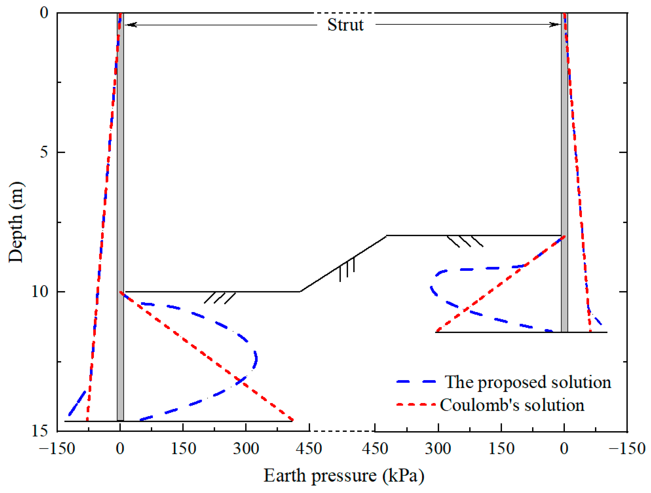
Figure 8.
Net pressure distribution on the braced retaining structure in asymmetric excavation.
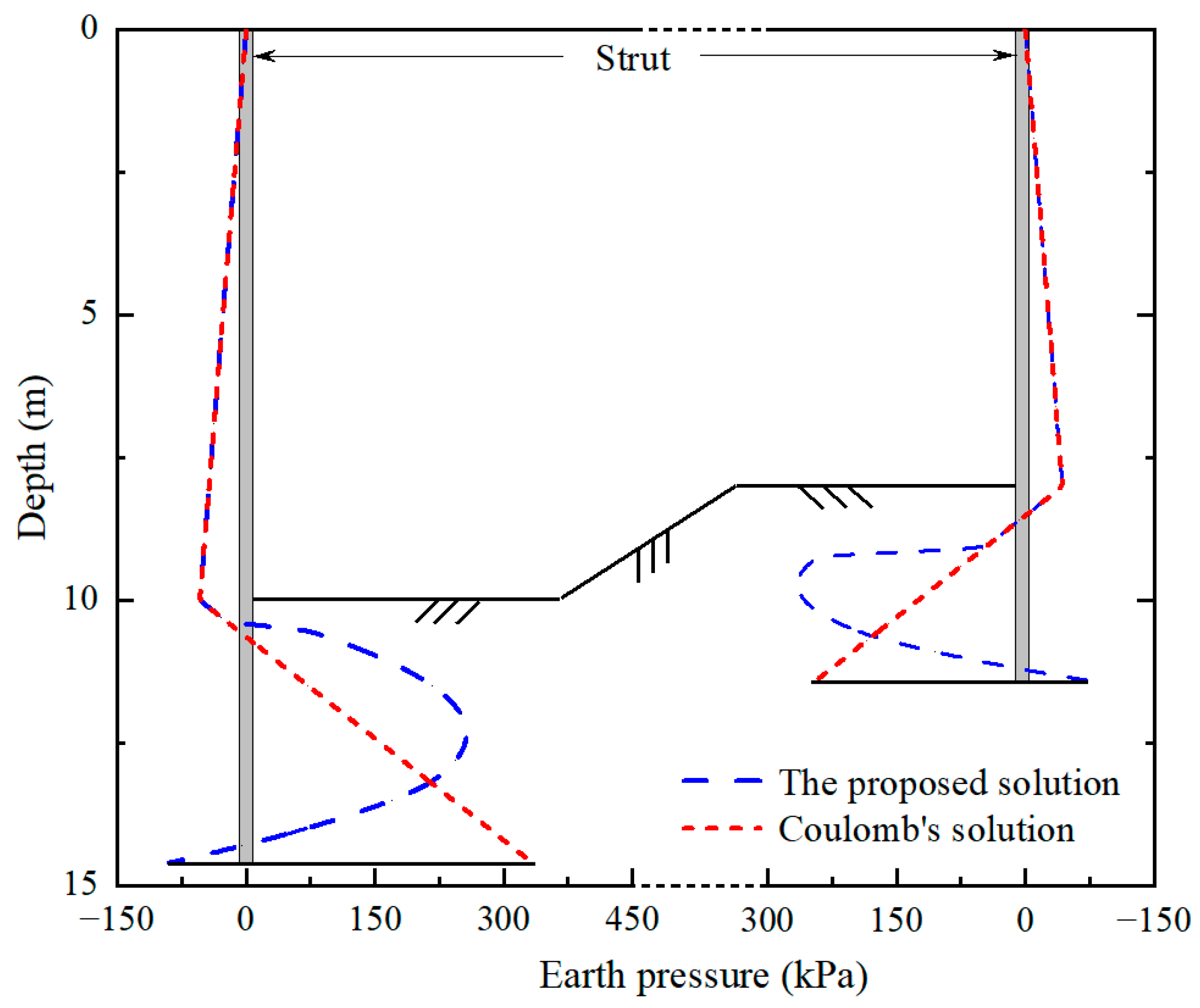
Figure 9.
Comparison of the Re values of both sides calculated in this study and using the classical equivalent-beam method (h1 = 10 m, h2 = 8 m).
Figure 9.
Comparison of the Re values of both sides calculated in this study and using the classical equivalent-beam method (h1 = 10 m, h2 = 8 m).
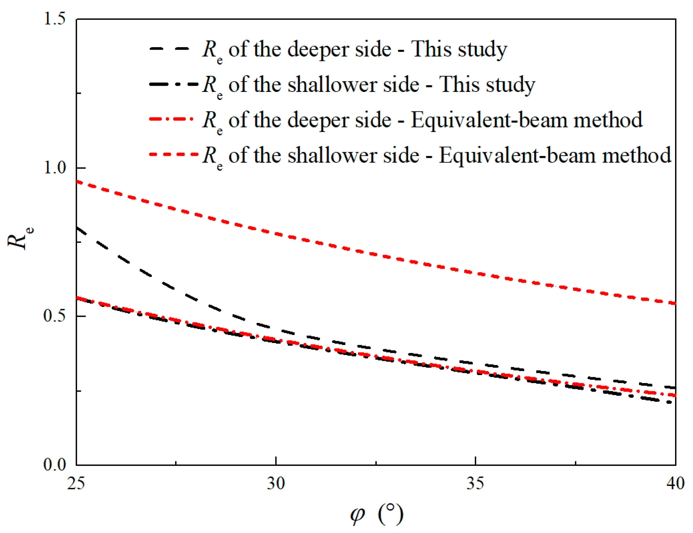
Figure 10.
Influence of strut stiffness on the Re values of both sides (h1 = 10 m, h2 = 8 m).

Figure 11.
Influence of the excavation depth differences between two sides on the Re value of the shallower side.
Figure 11.
Influence of the excavation depth differences between two sides on the Re value of the shallower side.

Figure 12.
Influence of the deformation control values on Re values of both sides.


Table 1.
Soil parameters.
| Parameter | Value | Parameter | Value |
|---|---|---|---|
| (°) | 30 | K0 | 0.50 |
| (kN/m3) | 18 | Ka | 0.30 |
| sa | 1‰L | Kp | 4.98 |
| sp | 1%(L − h) | δ (°) | 15 |
Table 2.
Strut arrangement parameters.
| EA (kN) | B (m) | S (m) |
|---|---|---|
| 1.854 × 10⁶ | 30 | 15 |
Table 3.
Calculation results for cases of different deformation control values.
| Group | [Δ]t/mm | [Δ]m/mm | L1/m | Re of the Deeper Side | L2/m | Re of the Shallower Side |
|---|---|---|---|---|---|---|
| 1 | 20 | 50 | 14.6 | 0.46 | 11.3 | 0.42 |
| 2 | 20 | 45 | 15.0 | 0.50 | 11.3 | 0.42 |
| 3 | 20 | 40 | 15.7 | 0.57 | 11.3 | 0.42 |
| 4 | 20 | 35 | 16.7 | 0.67 | 11.5 | 0.43 |
| 5 | 20 | 30 | 18.4 | 0.84 | 12.2 | 0.52 |
| 6 | 15 | 50 | 14.8 | 0.48 | 11.6 | 0.45 |
| 7 | 10 | 50 | 15.1 | 0.51 | 11.8 | 0.47 |
Disclaimer/Publisher’s Note: The statements, opinions and data contained in all publications are solely those of the individual author(s) and contributor(s) and not of MDPI and/or the editor(s). MDPI and/or the editor(s) disclaim responsibility for any injury to people or property resulting from any ideas, methods, instructions or products referred to in the content. |
© 2024 by the authors. Licensee MDPI, Basel, Switzerland. This article is an open access article distributed under the terms and conditions of the Creative Commons Attribution (CC BY) license (https://creativecommons.org/licenses/by/4.0/).
Share and Cite
MDPI and ACS Style
Fan, X.; Xu, C.; Liang, L.; Feng, G.; Wan, Q. Analytical Method for the Deformation-Based Design of Retaining Walls in Asymmetric Excavation. Buildings 2024, 14, 1321. https://doi.org/10.3390/buildings14051321
AMA Style
Fan X, Xu C, Liang L, Feng G, Wan Q. Analytical Method for the Deformation-Based Design of Retaining Walls in Asymmetric Excavation. Buildings. 2024; 14(5):1321. https://doi.org/10.3390/buildings14051321
Chicago/Turabian StyleFan, Xiaozhen, Changjie Xu, Luju Liang, Guohui Feng, and Qiwei Wan. 2024. "Analytical Method for the Deformation-Based Design of Retaining Walls in Asymmetric Excavation" Buildings 14, no. 5: 1321. https://doi.org/10.3390/buildings14051321
Note that from the first issue of 2016, this journal uses article numbers instead of page numbers. See further details here.