
Mechanical Properties of Folding Arch Frame Joints for Unmanned Arch Erection
1
China Railway 15th Bureau Group Co., Ltd., Shanghai 200070, China
2
China Railway 15th Bureau Group No. 5 Engineering Co., Ltd., Tianjin 300133, China
3
School of Civil Engineering, Lanzhou Jiaotong University, Lanzhou 730070, China
*
Author to whom correspondence should be addressed.
Buildings 2024, 14(5), 1480; https://doi.org/10.3390/buildings14051480
Submission received: 11 April 2024
/
Revised: 14 May 2024
/
Accepted: 17 May 2024
/
Published: 19 May 2024
(This article belongs to the Special Issue Research on Rate-Dependent Mechanical Properties of Ultra-High Strength Concrete)
Abstract
:The application of folding arch frames is deemed crucial for unmanned arch frame erection, with the selection of the joint form being a determining factor in the overall mechanical performance of the folding arch frame, particularly in influencing the primary support safety. In light of the geological conditions of the New Wushaoling Tunnel project, three feasible joint forms for folding arch frames were proposed: buckle, adhesive, and interference-fit joints. Numerical simulations were conducted to analyze the arch’s overall mechanical and the joints’ local mechanical performances, aiming to identify the optimal joint form. On-site construction data were collected, and the effectiveness of unmanned arch frame erection was evaluated. The design requirements for the vertical displacement results of the steel arches with different joints were met. The maximum shear stress of the buckled arch frame was found to be the lowest, whereas that of the interference-fitted arch frame was the highest. The local shear stress of the adhesive joints was the lowest, while that of the interference-fit joint was the highest. Considering the material application limitations and calculation results, buckle joints are recommended. Unmanned arch frame erection, compared with manual arch frame erection, can save 66.6% of human resources and reduce the construction time by 33.3% to 50%. Statistical analysis has confirmed that the quality of automated arch construction can be guaranteed.
1. Introduction
The primary support during tunnel construction traditionally relies on manual arch frame erection. Workers perform the task of steel arch erection under an unsupported surrounding rock, facing risks such as tunnel collapse and rockfalls that may result in casualties. To enhance the safety of the construction personnel and address the inefficiency of manual arch frame erection, unmanned arch frame erection offers a promising alternative. In unmanned arch construction, the choice of connection method for folding steel arches emerges as a significant problem that limits the wider adoption and application of unmanned arch frame erection technology. Therefore, identifying the optimal joint form for folding arch frames is crucial for advancing the development of unmanned arch construction technologies.
Extensive research has been undertaken on unmanned arch erection. Guoan et al. [1] introduced a longitudinal steel plate connection system to tackle challenges associated with soft surrounding-rock construction. Their field test contrasted the steel plate with the conventional steel bar support among steel arch frames. Manchao et al. [2] developed an adaptive arch frame joint for tunnels with significant soft-rock deformation, utilizing energy release theory. The paper details the joint’s functionality across different deformation stages. Guozhong et al. [3] explored the issues related to steel arch frame segment connections for tunnel primary support and suggested enhancements for tunnel steel arch frame connections. Ma et al. [4] demonstrated that incorporating longitudinal connections in tunnel steel arch frames can reduce plastic and shotcrete damage, thus bolstering the primary support’s capacity under comparable stress conditions. Song et al. [5] conducted research on I-beam and hollow-pipe string joints through static and cyclic loading tests, offering an in-depth analysis of connection performance and its failure under various loading scenarios.
Xu et al. [6] introduced a grid steel frame-core tube support system, explaining its structure and assembly methods, and compared the strains between two arch supports: the conventional I-beam arch and their innovative structure. Li et al. [7] conducted an analysis of supports that integrate foot-lock pipes with steel frames, deriving a formula for foot-lock pipe deflection and internal forces that considers force and deformation coordination. They validated their theoretical findings through a practical example. Qiong et al. [8] designed a remote construction system for unmanned steel arch assembly by enhancing a grabbing device in integrated equipment, aiming to reduce the manual installation efforts.
Li et al. [9] investigated the compression-bending properties of casing joints in steel tubular supporting arches for tunnels, analyzing failure modes and Mu-Nu curves to understand bearing capacity. Gao et al. [10] investigated the bearing mechanism of a steel arch–concrete composite initial support system for large tunnels, focusing on multi-arch spatial combination and concrete shotcrete influence, offering design insights. Wu et al. [11] critically reviewed the performance of the yielding supports in squeezing tunnels, summarizing the key yielding elements, historical case studies, and applicability, offering recommendations for future research. Wang and Hu [12] used fuzzy PID control to minimize the forearm vibration in tunnel steel arch-mounting machines, achieving smooth velocity transitions and reducing self-vibration within 3 s for small-angle adjustments. Li et al. [13] suggested BGI for unmanned arch erection, improving tunnel construction in China by automating steel arch installation, anchor pipe construction, and shotcrete, reducing manual labor and ensuring rapid, safe construction. Santos et al. [14] found that embedding expanded polystyrene geofoam in trenches for buried corrugated steel arches reduces earth pressure, deflection, and crown stress, potentially enhancing the stability and cost-effectiveness. Zhang et al. [15] offer a method for deciding when to install initial tunnel support, based on safety and cost considerations, simplifying the construction feedback. Reza et al. [16] tested thinner bolted flange joints for petrochemical piping, finding that they performed well under seismic conditions, indicating their suitability for such applications. Song et al. [17] explored how earthquakes and subsequent fires impact steel connections, finding a reduced load capacity with prior damage, underlining the need to understand the structural behavior in these conditions. Song and Zhu [18] researched how steel arch frames support collapsing tunnels, revealing that they reduce the stress and displacement, with the spacing of impacting forces and bending.
Additional studies on unmanned arch erection construction have explored various angles, including new arch installation trolleys [19,20], prefabricated arch installation machines [21,22,23,24,25], and combined tool trucks for constructing tunnel sections [26,27,28,29].
Despite these investigations, quantitative research focusing on the choice of connections between arch segments remains limited. While there is agreement on the longitudinal connection of steel arch frames, the quantitative analysis of the connection mode between arch frame segments to address the demands of mechanized and unmanned construction requires further attention. The traditional method of connecting steel arch frame segments, primarily through positioning plates and high-strength bolts, is being reevaluated. In light of the unmanned arch erection at the New Wushaoling Tunnel and leveraging the existing tunnel multi-functional operation tool cart and the folding steel arch frame, three novel steel arch frame connection modes have been proposed. These modes were assessed for their mechanical properties through numerical simulation. The numerical analysis results facilitated a comparison of stress states, bearing capacities, and the stability of the steel arch frame under various connection modes, leading to the selection of the optimal connection scheme for the unmanned arch erection construction in the New Wushaoling Tunnel. To supplement this selection, on-site statistical data were analyzed to evaluate the quality, construction efficiency, and manpower savings of unmanned arch erection, thereby providing empirical support for the unmanned construction of tunnel steel arch frames.
2. Comparison and Selection of a Steel Arch Frame Connection Mode in Unmanned Arch Erection
Currently, the installation of steel arch frames in construction primarily relies on manual methods, necessitating workers to perform positioning, installation, and connection tasks within challenging and exposed environments of the surrounding rock [30,31,32,33]. Additionally, the construction process includes the installation of feet-lock pipes. Given that steel arch frames are often installed in areas with unfavorable geological conditions, the surrounding rock in these areas is prone to collapse and fall, presenting considerable safety hazards to on-site workers [34,35]. Moreover, the process of manually making bolt connections to adjacent segments of the steel arch frame further diminishes the overall efficiency of assembly. Therefore, there is an urgent need for a new type of folding steel arch frame that is conducive to mechanized construction to overcome these technical bottlenecks. In the development of this innovative steel arch frame, selecting an appropriate connection mode is of paramount importance. The research into this aspect has highlighted three commonly utilized folding steel arch frame connections at construction sites: buckle joints, adhesive joints, and interference-fit joints. The connection methods for these folding steel arch frames are depicted in Figure 1.
A buckle-joint steel arch frame, designed for mechanized construction, incorporates at least two arch frame units. These adjacent arch frame units are connected in a manner that allows for rotation, with the connecting ends featuring a buckle structure. This structure consists of conical ends on one arch frame unit and an elastic buckle position on the other, facilitated by a cavity and an elastic clamp ring to secure the cone ends. By employing two or more arch frame units, they are hinged together, while the adjacent arch frame units are simultaneously secured by the buckle structure. To further ensure stability, the connecting ends of the arch frame units are also manually bolted. This design not only enhances the installation efficiency of the arch frame units but also significantly reduces the construction effort required from workers.
Compared to other mechanical connection methods, adhesive joint steel arch frames offer significant benefits, including rapid construction, low labor intensity, and straightforward construction technology. This method facilitates quick assembly during installation, ensuring an efficient connection between steel arch frame segments. Adhesive joints distribute stress evenly, effectively preventing stress concentration and thereby safeguarding the joint structure from damage. Their load-bearing capacity rivals that of welding or riveting methods, with the added advantage of a superior seal that obviates the need for additional waterproofing measures. The adhesive joint steel arch frame is particularly valuable in the initial support installation for tunnels. It minimizes the risk to workers near the face of unstable surrounding rock and significantly reduces the labor intensity for installation crews. The adhesive joint is designed at the end of adjacent steel arch frame segments, allowing for flexible rotation and connection of the arch frame units, which facilitates mechanical installation. A robust connection between the arch frame segments is achieved by placing a cone end on one arch frame unit and a corresponding cavity on another to accommodate the cone head. A special adhesive applied inside the cavity ensures the connection. This innovative bonding structure not only enables a hinged rotating connection between the arch frame units but also secures the adjacent units through cementation. With no need for manual bolting at the connecting ends, the installation efficiency of the arch frame units is markedly improved, reducing the construction intensity for operators.
The interference-fit joint is a mechanical fixed installation method that involves fitting shaft components into holes where the shaft size is slightly larger than the hole. This ensures that the connector joint possesses sufficient strength, even with minimal interference. This method streamlines the connection structure by reducing the number of components required in the joint design, thereby simplifying the operation and control during assembly and processing. The reliability of the interference-fit assembly connection is comparable to that of bolt connections, making it well-suited for scenarios that require withstanding impact loads and are challenging to disassemble. In the context of mechanized construction, interference-fit assembly joints meet the necessary requirements and reduce the labor intensity for installation workers. Positioned between two arch units, this design allows adjacent arch units to be folded and connected for rotation. This is achieved through rotating hinge connections utilizing mechanical power, with interference-fit assembly joints installed between the steel arch segments. The overall structure features cylindrical ends with chamfers and accommodating cavities, designed to eliminate the need for manual assembly and the installation of the arch unit by workers. Thus, the installation efficiency of the arch unit is significantly improved, advancing the level of mechanized tunnel construction.
3. Numerical Simulation Study on the Mechanical Properties of Different Joint Forms
3.1. Engineering Background
The entrance of the New Wushaoling Tunnel is located in the town of Dachaigou, Tianzhu County, with its exit in the town of Anyuan. The tunnel reaches a maximum burial depth of 952 m and spans a total length of 17,125 m. An installation test of a prefabricated steel arch was carried out in the entrance section of the New Wushaoling Tunnel, utilizing the long-step construction method. This method features an upper step height of 7.11 m, a lower step height of 3.05 m, and step lengths ranging from 35–50 m. The cross-sectional dimensions of the tunnel are shown in Figure 2.
3.2. Numerical Model Establishment
The upper-stage steel arch was segmented into three parts, with the steel arch connection devices strategically placed at 45° angles on both sides of the tunnel’s centerline. For the modeling process, the load structure method was employed using ABAQUS 2020 finite element software. This approach entailed applying vertical and horizontal surrounding rock pressures directly to the steel arch. Due to the anchoring effect provided by the bolt at the base of the arch, the boundary constraint condition for the arch foot at both ends of the steel arch frame was completely fixed. The steel arch’s grid division approach utilized a structured grid, with the element type designated as C3D8R (a linear reduced integral element featuring eight nodes and a hexahedral shape). The grid size is automatically divided. The typical grid size of a steel frame is 50 × 50 × 22 mm. The typical grid size at the joint is about 3 × 3 × 3 mm, and the grid is encrypted at the connections.
To enhance the reliability of the simulation results, the calculation model was simplified. The simulation of the hinge device connecting the end steel plates in ABAQUS was achieved through the combined connection attribute HINGE. This attribute integrates the translation connection attribute JOIN with the rotation connection attribute REVOLUTE, allowing for no relative translation between two joining points and permitting only relative rotation in a specific direction. For buckle joints, the ends of the segments are precision-engineered to facilitate the connection of steel plates through articulation, with a self-locking mechanism achieved by installing two high-strength conical ends on the outer arc side of one steel plate and an accommodating cavity equipped with a spring clasp on the other steel plate. The material used for the conical end buckle joints is carbon structural steel, with a tensile strength of 800 MPa and a yield strength of 640 MPa. The function of the spring buckles is simplified in the model to restrict the conical end, effectively mirroring the operational mechanism of the connecting device.
For adhesive joints, a high-strength epoxy resin adhesive is pre-applied to the end plate of the steel arch. The epoxy resin adhesive can offer a tensile strength of up to 30 MPa and a shear strength of up to 35 MPa. During the assembly of the steel arch segments, the end plate is securely bonded. The model assumes that the adhesive’s bonding strength remains intact under the surrounding rock pressure, effectively binding and constraining the contact surfaces between the connecting plates. This approach simulates the use of high-strength adhesives and facilitates the analysis of the stress characteristics of the steel arches.
In the case of interference-fit joints, a cylindrical end with a chamfer on the end plate of a steel arch unit is mechanically inserted into a pre-designed holding cavity. This process utilizes the elastic deformation of the cavity to achieve a secure connection. The end of the joint is tightly bound to the contact surface within the cavity, mimicking the interference connection and enabling the analysis of the mechanical characteristics of the steel arch. The unmanned folding arch frame model, along with the different forms of joint local structures, is depicted in Figure 3.
3.3. Load Parameters
According to the geological exploration report for the entrance section of the New Wushaoling Tunnel, the inlet section is classified as Grade V soft surrounding rock. Utilizing the damage stage method recommended by the current Code for the Design of Railway Tunnels, the vertical and horizontal surrounding rock pressures were determined to be 259.2 kPa and 103.7 kPa, respectively. The material parameters for the model I-beam are detailed in Table 1. The locking of the buckle ring on the conical ends is achieved through “Tie” constraints. The contact type between connection plates is “hard” contact. This type ignores the tangential friction and only considers normal contact relationships, allowing for separation after contact.
4. Numerical Simulation Results of the Mechanical Properties of Steel Frames with Different Types of Joint Forms
4.1. Mechanical Properties of Steel Arches under Different Connection Modes
A comparative analysis focusing on the deformation of folding steel arches employing various connection methods is depicted in Figure 4. Under the influence of the surrounding rock pressure, the displacement distribution trend of steel arches remains consistent across different connection modes. The vertical displacement at the top of the steel arch reaches its maximum value and gradually diminishes toward both sides. When adhesive joints are utilized between the sections of the arch frame, the vertical displacement of the steel arch is the smallest, measuring 65.0 mm. For arch frames connected by buckle joints, adhesive joints, and interference-fit joints, the vertical displacements recorded are 70.6 mm, 70.4 mm, and 70.5 mm, respectively. This indicates that adhesive joints are more effective in controlling the deformation of the steel arch within the segment connections.
The comparative analysis of the principal stresses in steel arches using different connection methods reveals significant insights. As depicted in Figure 5, under the influence of varying connection methods and the surrounding rock pressure, the maximum principal stress within the steel arch frame is predominantly compressive, while the minimum principal stress is notably tensile. Stress concentration is primarily observed at the arch foot position. Therefore, when installing the steel arch in a tunnel, it is essential to reinforce the arch foot position to prevent damage at this critical juncture. Even when employing a joint form suitable for unmanned arch construction, the location of the stress concentration in the steel arch remains unchanged, still manifesting at the arch foot position. This indicates that the method of connection between the steel arch segments does not alter the position of the stress concentration within the arch.
When employing a buckle as the connection method between I-beam segments, the maximum compressive stress recorded is 51.6 MPa, and the maximum tensile stress is 34.8 MPa. For adhesive joints, the corresponding stresses are 74.9 MPa (compressive) and 28.2 MPa (tensile), while the interference-fit joint bears a maximum compressive stress of 43.9 MPa and a maximum tensile stress of 83.4 MPa. Notably, the adhesive joint is prone to brittle fracture as its failure mode. According to the first strength theory, the steel arch’s maximum tensile stress is 83.4 MPa. Hence, the stability of the steel arch can be ensured as long as the adhesive’s bonding tensile strength exceeds this maximum tensile stress. The failure modes of the other joints align with the plastic yield theory. Based on the third strength theory, the maximum shear stresses for the buckle connection and the interference-fit connection are 86.4 MPa and 127.3 MPa, respectively. Analysis reveals that the maximum shear stress for the interference-fit connection assembly surpasses the shear yield strength of a No.16 I-beam by 125 MPa, indicating that the buckle connection, with its minimized maximum shear stress, offers a safer structural option.
4.2. Mechanical Properties of Local Joint Positions under Different Connection Methods
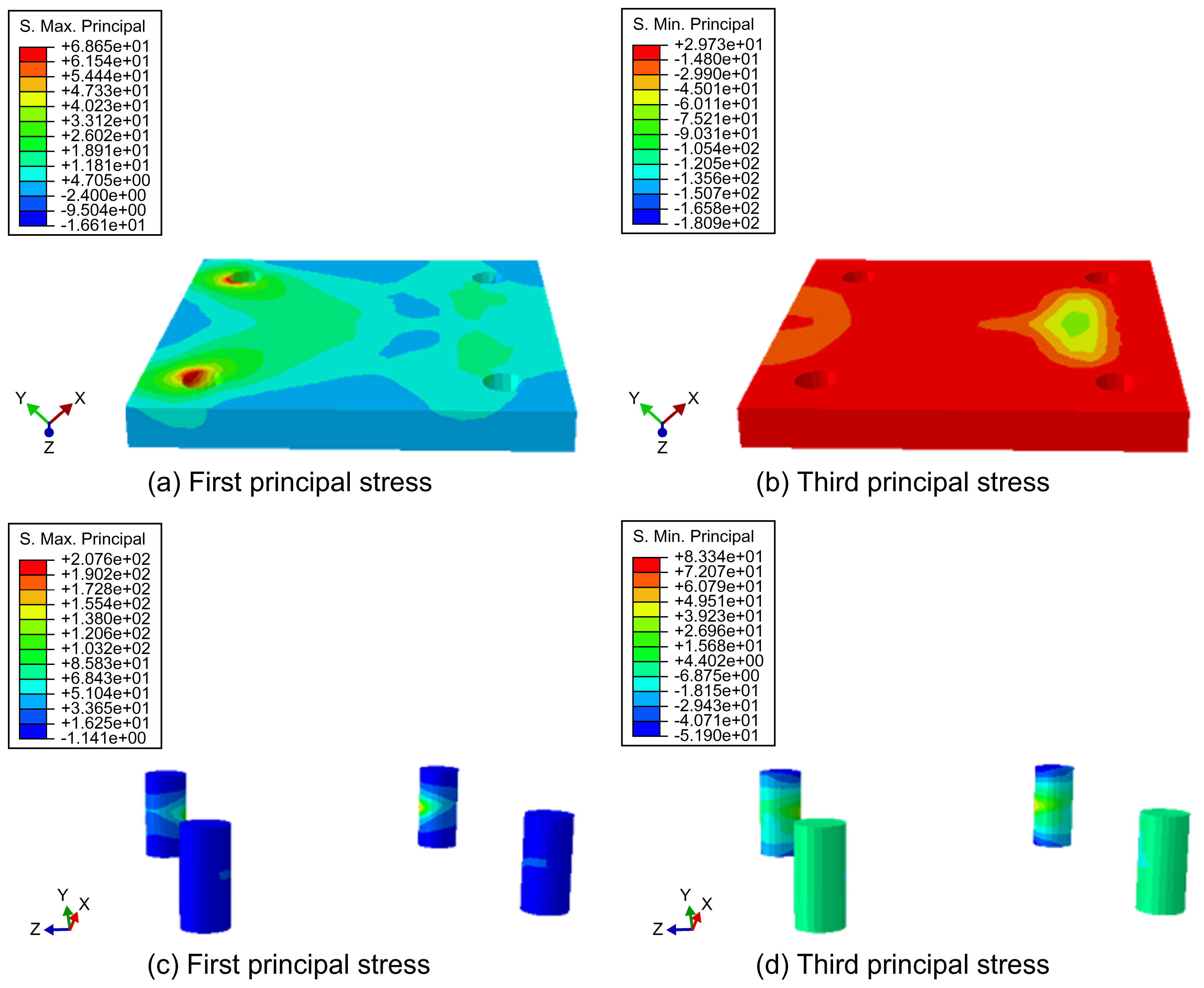
Utilizing the strength theory of material mechanics, a comparative analysis was performed on steel arch joints featuring various joint forms. The mechanical performance outcomes for the buckle joint are shown in Figure 6.
When employing a buckle connection, the maximum tensile stress observed on the elastic cone head is 166.0 MPa, which represents a decrease of 138.3 MPa compared to bolted connections. The area of stress concentration is primarily located at the connection point between the cone head and the positioning steel plate. The maximum compressive stress recorded is 52.8 MPa. According to the theory of maximum shear stress, the maximum shear stress experienced by the elastic cone head connected via the buckle is 218 MPa, which is below the designed shear strength of 250 MPa, indicating that the joint is safely within the acceptable stress limits.
The interference-fit joint, as depicted in Figure 7, features an accommodating cavity at the steel plate end. This cavity is constrained by the clamping force generated through the interference-fit assembly method, effectively limiting the deformation at both ends of the steel plate. The stress concentration for the interference-fit assembly steel arch primarily occurs in the middle of the cylindrical end, with the maximum tensile stress reaching 207.6 MPa—positioned between the bolted connection and the buckle connection stress levels. According to the theory of maximum shear stress, the maximum shear stress for the interference-fit cylindrical–conical heads is 259.6 MPa, which surpasses the design strength, indicating a potential risk under extreme stress conditions. The interference-fit joint demands high precision in the dimensional accuracy of the structural components. Moreover, the assembly process necessitates external extrusion to insert the end into the cavity, posing certain challenges in the context of tunnel field construction due to these stringent requirements and the complexity of the installation process.
4.3. Comparative Analysis of Mechanical Properties of Different Joint Forms
The mechanical properties of folded arch frames employing various joint forms are detailed in Table 2. A comparison of the vertical displacement angle across the arch frames indicates that all three joint forms satisfy the maximum displacement limit requirements. Regarding the maximum stress experienced by the arch frames, the interference-fit type exhibits the highest maximum shear stress, surpassing the shear designed strength of the I16 I-beam, whereas the buckle joint arch demonstrates the lowest maximum shear stress. Specifically, the maximum shear stress for the buckle joint was 218 MPa, below the joint’s maximum designed shear strength of 250 MPa. For adhesive joints, commonly used adhesives such as Araldite (2015) can offer a tensile strength of up to 30 MPa and a shear strength of up to 35 MPa. However, adhesive joints face challenges in fulfilling the design requirements due to the complexities involved in their application. Factors such as the surface treatment of the steel arch joint, the adhesive application method, and the adhesive’s curing degree significantly influence the ultimate strength of the joint. Therefore, after considering all the pertinent factors, including the construction convenience and mechanical performance, the buckle-joint connection method emerges as the preferable choice.
5. Case Study of Unmanned Arch Erection in the New Wushaoling Tunnel
5.1. Application Example of Unmanned Arch Erection in the New Wushaoling Tunnel
The New Wushaoling Tunnel, extending 17.125 km above the existing line on the Lanwu Second Line, is pivotal for the Lanzhou–Zhangjiakou Third and Fourth Railways. Undertaken by the China Railway 15th Bureau, the entrance section spans 8021 m, with Grade IV and V rocks comprising 87.6% of the geological profile. The project benefits from seven active working fronts, facilitated by strategically positioned inclined shafts.
In light of the structural dimensions critical for arch erection and the practical feasibility of the construction approach, an innovative trial of “unmanned” arch erection was initiated in the entrance work zone of the New Wushaoling Tunnel. Situated at an altitude of 2800 m, the entrance work area’s surrounding rock predominantly falls within grades III and IV, with a primary composition of sandstone lithology. The site maintains operational stability, free from concerns of falling debris or water ingress. Utilizing the benching tunneling method, the construction features included an upper step height of 7.11 m and a lower step height of 3.05 m, with step lengths ranging between 35 and 50 m. Advancements were made at a rate of 2–2.4 m per cycle, with the erection of arch frames using 16 and 18 I-shaped steel models, occurring at an average pace of two frames every three cycles, each accomplished within a two-day period.
From October to November 2020, the construction process within the tunnel was meticulously executed, undergoing continuous exploration, enhancement, and refinement. This iterative process culminated in the successful on-site application of the final construction method, leading to a substantial improvement in the efficiency of arch erection. As a result, the workforce required for arch erection was significantly reduced from nine to three workers, and the installation time for one arch frame was decreased from 1.5–2 h to just 1 h per frame.
Through repeated cycles of experimentation, application, innovation, and refinement in managing the unmanned processes of arch erection, drilling, anchoring, and injection, this construction method has achieved remarkable advancements. These improvements have been pivotal in enhancing its practical application, offering a stark contrast to traditional methods that depend heavily on manual labor and workbenches. This innovative approach has proven to be superior in terms of safety, construction efficiency, and economic benefits. The next phase focuses on the dissemination and implementation of this method, aiming to deliver substantial economic and social advantages to both projects and enterprises.
5.2. Quality Analysis of Unmanned Arch Erection in the New Wushaoling Tunnel
After the welding of the arch and the securing of its feet, conducting a meticulous inspection and acceptance of the arch frame installation quality became a crucial responsibility for the on-site technicians and supervisors. Our attention was particularly focused on evaluating the key indicators such as arch spacing, lateral position deviation, and inclination. We conducted separate assessments for 50 arch frames installed manually and those deployed via unmanned trolleys. The findings underscored that the unmanned arch erection construction achieved a perfect 100% qualification rate for arch spacing deviation, with an average deviation of 40 mm. In comparison, manual arch erection construction also boasted a 100% qualification rate, albeit with a slightly better average deviation of 25 mm. For lateral position deviation, both unmanned and manual arch erection methods reached a 100% qualification rate, with average deviation values of 9 mm and 11 mm, respectively. In the inclination analysis, unmanned arch erection construction attained a commendable 96% qualification rate, with an average inclination of 0.5°, whereas the manual arch erection construction showed a slightly superior performance, with a validity rate of 98% and an average inclination of 0.4°.
A comprehensive statistical analysis was carried out on the settlement and convergence measurements across 40 sections within the unmanned arch erection segment. The statistical results are shown in Table 3. This analysis revealed that the cumulative maximum value of settlement deformation reached 41.1 mm, and the cumulative maximum value of peripheral convergence was 43.6 mm. Similarly, 40 cross-sections were analyzed for sections erected manually under identical surrounding rock conditions, showing that the cumulative maximum value of settlement deformation was 47.5 mm, and the cumulative maximum value of peripheral convergence was 48.2 mm.
These findings highlight that, in terms of controlling the arch frame spacing and inclination, the precision of unmanned arch erection currently falls short of manual arch erection. However, when it comes to the accuracy of lateral position control, unmanned arch erection demonstrates superiority. Moreover, the lower cumulative maximum values for settlement and convergence observed in the unmanned arch erection sections, compared to those in the manual erection sections, suggest that unmanned arch erection maintains, if not enhances, the quality of arch construction.
5.3. Benefit Analysis of Unmanned Arch Erection in the New Wushaoling Tunnel
The adoption of unmanned arch erection construction has dramatically reduced the workforce needed for arch frame construction from nine individuals to a lean team comprising one operator and two workers. This shift significantly reduces the labor intensity, as machinery takes over the tasks previously performed manually. With seven working faces and a construction period of 20 months, this innovative approach has led to a monthly workforce reduction of 840 individuals. This equates to a substantial saving of 66.6% in human resources compared to the traditional manual arch erection construction plan, which will significantly reduce costs. Moreover, by implementing this method, the safety risks associated with collapses and falling blocks are effectively mitigated, further enhancing the safety and efficiency of construction projects.
The deployment of unmanned arch erection construction has marked a significant improvement in construction efficiency over the traditional manual method. The time required to install a single arch frame has been halved, dropping from 1.5–2 h per frame to just 1 h. With the construction progressing at an average rate of two 1.6 m cycles, this equates to a time saving of 1.5 h per cycle. Applied to a tunnel extending 8000 m, the total time saved amounts to 7500 h, which translates to 312 d or an average saving of 45 d per working face across the seven faces. In comparison to manual arch erection construction, this innovative method results in a construction time reduction of 33.3% to 50%. The efficiency gains are detailed in Table 4, showcasing the considerable advantages in work efficiency brought about by the unmanned construction approach.
6. Conclusions
This study focuses on the construction of unmanned arch erection under the load conditions in the New Wushaoling Tunnel. Through numerical simulation, we analyzed three different joint forms of the arch frame—buckle, adhesive, and interference-fit joints—and assessed their local mechanical characteristics. Additionally, the on-site application of unmanned arch erection in the New Wushaoling Tunnel was explored and analyzed, leading to the following conclusions:
- (1)
- Under identical load conditions, the maximum vertical displacements for all three types of joint forms were similar and met the requirements for tunnel construction. In terms of the maximum stress experienced by the arch frame, the buckle-joint arch frame exhibited the lowest maximum shear stress, while the interference-fit joint arch frame showed the highest. Regarding the local shear stress of the joints, the adhesive joint arch frame had the lowest shear stress, and the interference-fit joint arch frame had the highest.
- (2)
- Taking into account the overall mechanical performance of the arch frame, the local mechanical performance of the joints, the performance limitations of bonding materials, and construction difficulties, we recommend the use of buckle joints for connecting folding arch frame joints in unmanned arch erection.
- (3)
- A statistical analysis of the on-site construction at the New Wushaoling Tunnel reveals that unmanned arch erection employing buckle joints offers significant advantages over manual arch erection. The findings indicate that the construction quality of arch erection is maintained while achieving a 66.6% reduction in human resources and a 33.3% to 50% decrease in the construction time.
- (4)
- This study was conducted under the specific load and surrounding rock conditions of the New Wushaoling Tunnel, with uniform joint positions. Future research aims to broaden the scope, analyzing the local mechanical properties of arch frames and joints under varied working conditions, as well as the impact of different joint layout positions on their mechanical properties. The goal is to develop optimized construction techniques for various joint forms.
Author Contributions
Software, S.L.; investigation, S.L., W.L., T.Y. and D.L.; writing—original draft preparation, S.L.; writing—review and editing, D.L.; supervision, C.H.; project administration, W.L., T.Y. and Y.X.; funding acquisition, C.H. All authors have read and agreed to the published version of the manuscript.
Funding
This research was funded by the Research and Development Projects of Science and Technology of China Railway Construction Co., Ltd. and the China Railway 15th Bureau Group Co., Ltd., grant numbers N2020G040, 2018-C09, and 2017A1.
Data Availability Statement
The raw data supporting the conclusions of this article will be made available by the authors on request.
Conflicts of Interest
Authors Changfu Huang, Shaohua Li, Wenbing Li, Tiejun Yao and Yong Xiao were employed by the companies China Railway 15th Bureau Group Co., Ltd. and China Railway 15th Bureau Group No. 5 Engineering Co., Ltd. The remaining authors declare that the research was conducted in the absence of any commercial or financial relationships that could be construed as a potential conflict of interest.
References
- Li, G.; Wang, Y.; Nie, Y. Study on longitudinal connection support structure of steel plate between steel arches of soft rock tunnel. Highway 2022, 67, 411–418. (In Chinese) [Google Scholar]
- He, M.; Wang, B.; Tao, Z.; Qiao, Y.; Xiao, Y. Axial compression behavior of adaptive steel arch joint for large-deformation tunnels. Chin. J. Highw. Transp. 2021, 34, 1–10. (In Chinese) [Google Scholar] [CrossRef]
- Yue, G. Some suggestions on the connection of steel arch frame in tunnel construction. Shandong Ind. Technol. 2015, 23, 86–87. (In Chinese) [Google Scholar] [CrossRef]
- Ma, K.; Zhang, J.; Zhang, J.; Wang, Z.; Feng, J. Longitudinal connection effect on initial support steel frames in tunnels—Take the traffic tunnels as examples. Undergr. Space 2022, 7, 608–622. [Google Scholar] [CrossRef]
- Song, Q.Y.; Heidarpour, A.; Zhao, X.L.; Han, L. Performance of flange-welded/web-bolted steel I-beam to hollow tubular column connections under seismic load. Thin Walled Struct. 2017, 116, 250–264. [Google Scholar] [CrossRef]
- Xu, F.; Li, S.; Zhang, Q.; Li, L.; Shi, S.; Zhang, Q. A new type support structure introduction and its contrast study with traditional support structure used in tunnel construction. Tunn. Undergr. Space Technol. 2017, 63, 171–182. [Google Scholar] [CrossRef]
- Chen, L.J.; Zhang, Y.L.; Ma, Z.Y. Analytical approach for support mechanism of feet-lock pipe combined with steel frame in weak rock tunnels. KSCE J. Civ. Eng. 2016, 20, 2965–2980. [Google Scholar] [CrossRef]
- Ni, P. Research and application of new type of tunnel supporting equipment, steel arch installation trolley. China Plant Eng. 2020, 18, 12–13. (In Chinese) [Google Scholar]
- Yan, Q. A remote unmanned construction system for steel arch erection developed by Japan Toda Construction Corporation. Tunn. Constr. 2021, 41, 387. (In Chinese) [Google Scholar]
- Li, W.; Yang, N.; Mei, Y.; Zhang, Y.; Wang, L.; Ma, H. Experimental investigation of the compression-bending property of the casing joints in a concrete filled steel tubular supporting arch for tunnel engineering. Tunn. Undergr. Space Technol. 2020, 96, 103184. [Google Scholar] [CrossRef]
- Gao, X.; Luan, Y.; Hu, C.; Lu, W.; Sun, H.; Liu, B.; Zhou, L. Study on bearing mechanism and coupling mechanism of steel arch-concrete composite structure of initial support system of large section tunnel. Geotech. Geol. Eng. 2019, 37, 4877–4887. [Google Scholar] [CrossRef]
- Wu, K.; Shao, Z.; Qin, S.; Wei, W.; Chu, Z. A critical review on the performance of yielding supports in squeezing tunnels. Tunn. Undergr. Space Technol. 2021, 115, 103815. [Google Scholar] [CrossRef]
- Wang, Z.Y.; Hu, S.C. Research on fuzzy PID control of forearm of tunnel steel arch mounting machine. J. Phys. Conf. Ser. 2019, 1187, 032072. [Google Scholar] [CrossRef]
- Li, D.; Lei, X.; Zhang, G.; Cao, M. The Study on the Construction Method of Bolting-Grouting Integrated Operation for Unmanned Arch Erection. 2021. Available online: https://www.researchsquare.com/article/rs-812381/v1 (accessed on 16 May 2024).
- Santos RR, V.; Kang, J.; Park, J.S. Effects of embedded trench installations using expanded polystyrene geofoam applied to buried corrugated steel arch structures. Tunn. Undergr. Space Technol. 2020, 98, 103323. [Google Scholar] [CrossRef]
- Zhang, Y.J.; Su, K.; Zhu, H.Z.; Qian, Z.D.; Wu, H.G. Installation time of an initial support for tunnel excavation upon the safety factors of surrounding rock. Appl. Sci. 2020, 10, 5653. [Google Scholar] [CrossRef]
- Reza, M.S.; Bursi, O.S.; Paolacci, F.; Kumar, A. Enhanced seismic performance of non-standard bolted flange joints for petrochemical piping systems. J. Loss Prev. Process Ind. 2014, 30, 124–136. [Google Scholar] [CrossRef]
- Song, Q.Y.; Heidarpour, A.; Zhao, X.L.; Han, L.H. Post-earthquake fire performance of flange-welded/web-bolted steel I-beam to hollow column tubular connections. Thin-Walled Struct. 2017, 116, 113–123. [Google Scholar] [CrossRef]
- Song, X.; Zhu, J. Analysis of Supporting Mechanism of Steel Arch Frame in Tunnel Collapse. In IOP Conference Series: Earth and Environmental Science; IOP Publishing: Bristol, UK, 2020; Volume 455, p. 012159. [Google Scholar]
- Guo, J.B.; Chen, J.; Liu, J.Z.; Niu, J.C. Multifunctional integration equipment design and construction technology research. Adv. Mater. Res. 2013, 650, 359–363. [Google Scholar] [CrossRef]
- Cheng, J.; Gong, Y.D.; Liu, Y.M. Investigation on key technology of virtual assembly and construction for tunnel boring machine. Appl. Mech. Mater. 2011, 71–78, 3375–3378. [Google Scholar] [CrossRef]
- Wang, Q.; Luan, Y.; Jiang, B.; Li, S.; He, M.; Sun, H.; Qin, Q.; Lu, W. Study on key technology of tunnel fabricated arch and its mechanical mechanism in the mechanized construction. Tunn. Undergr. Space Technol. 2019, 83, 187–194. [Google Scholar] [CrossRef]
- Wang, Q.; Qin, Q.; Jiang, B.; Xu, S.; Zeng, Z.; Luan, Y.; Liu, B.; Zhang, H. Mechanized construction of fabricated arches for large-diameter tunnels. Autom. Constr. 2021, 124, 103583. [Google Scholar] [CrossRef]
- He, Y.; Yang, M.; Xu, Z.; Li, S.; Zhang, B. Design of tunnel steel arch looping manipulator with multiple actuators in limited space. Sci. Prog. 2023, 106, 368504231180025. [Google Scholar] [CrossRef] [PubMed]
- Zhang, H.; Sun, J.; Ma, H.; Chen, S.; Huang, M. Development and application of mechanized matching equipment for high-speed railway tunnel construction. Procedia Manuf. 2019, 32, 952–959. [Google Scholar] [CrossRef]
- Gao, J.; Lin, X. Study on supporting technology for mechanized construction of high-speed railway tunnel. In Proceedings of the International Conference on Education Science and Economic Management (ICESEM 2017), Xiamen, China, 14–15 October 2017; pp. 411–414. [Google Scholar] [CrossRef]
- Krauze, K.; Bołoz, Ł.; Mucha, K.; Wydro, T. The mechanized supporting system in tunnelling operations. Tunn. Undergr. Space Technol. 2021, 113, 103929. [Google Scholar] [CrossRef]
- Kang, B. A new type of steel rib installing machine used in tunneling. Suidao Jianshe/Tunn. Constr. 2011, 31, 624–628. [Google Scholar]
- Miliziano, S.; de Lillis, A. Predicted and observed settlements induced by the mechanized tunnel excavation of metro line C near S. Giovanni station in Rome. Tunn. Undergr. Space Technol. 2019, 86, 236–246. [Google Scholar] [CrossRef]
- Lin, P.H.; Tserng, H.P.; Lin, C.C. Automated construction of the Paghuashan tunnel for Taiwan High Speed Rail (THSR) project. Autom. Constr. 2006, 15, 627–639. [Google Scholar] [CrossRef]
- Wu, Y.; Tian, C.; Xu, P.; Zhao, Z.; Zhang, J.; Wang, S. Design optimization method of feet-lock steel pipe for soft-rock tunnel based on load-deformation coordination. Appl. Sci. 2022, 12, 3866. [Google Scholar] [CrossRef]
- Sun, H. Study on Stability Bearing Mechanism and Key Technologies of Assembly Confined Concrete Support for Large Section Tunnel; Shandong University: Jinan, China, 2019. (In Chinese) [Google Scholar]
- Zhang, G.; Li, D.; Lei, X. Folding steel arch frame applicable to mechanized construction of tunnels and its key techniques. Tunn. Constr. 2022, 42, 445–450. (In Chinese) [Google Scholar]
- National Railway Administration of the People’s Republic of China. Code for Design of Railway Tune: TB 10003–2005; China Railway Publishing House: Beijing, China, 2001. (In Chinese)
- Xia, Y.; Wang, Y. Mechanical Calculation of Tunnel Structure; People’s Transportation Publishing House: Beijing, China, 2012. (In Chinese) [Google Scholar]
Figure 1.
Connection method of folding steel arch frames.
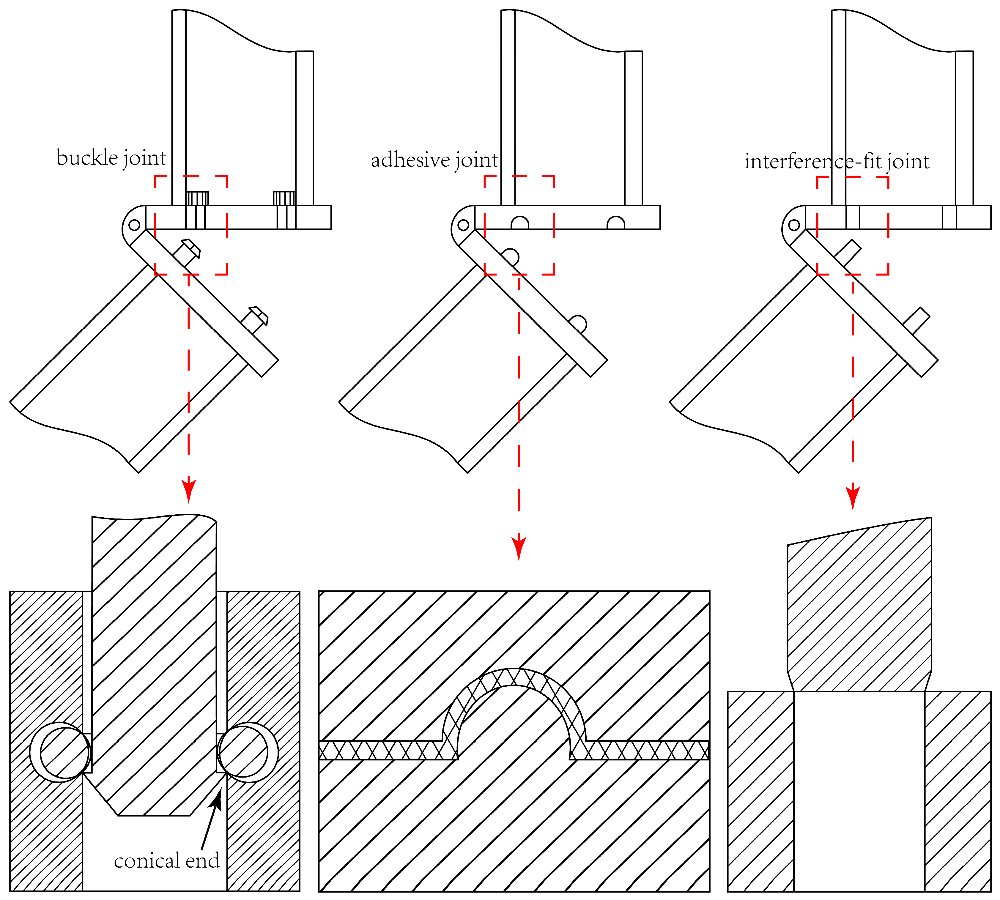
Figure 2.
Tunnel section dimensions (cm).

Figure 3.
Unmanned arch frame model and different forms of joint local structures.
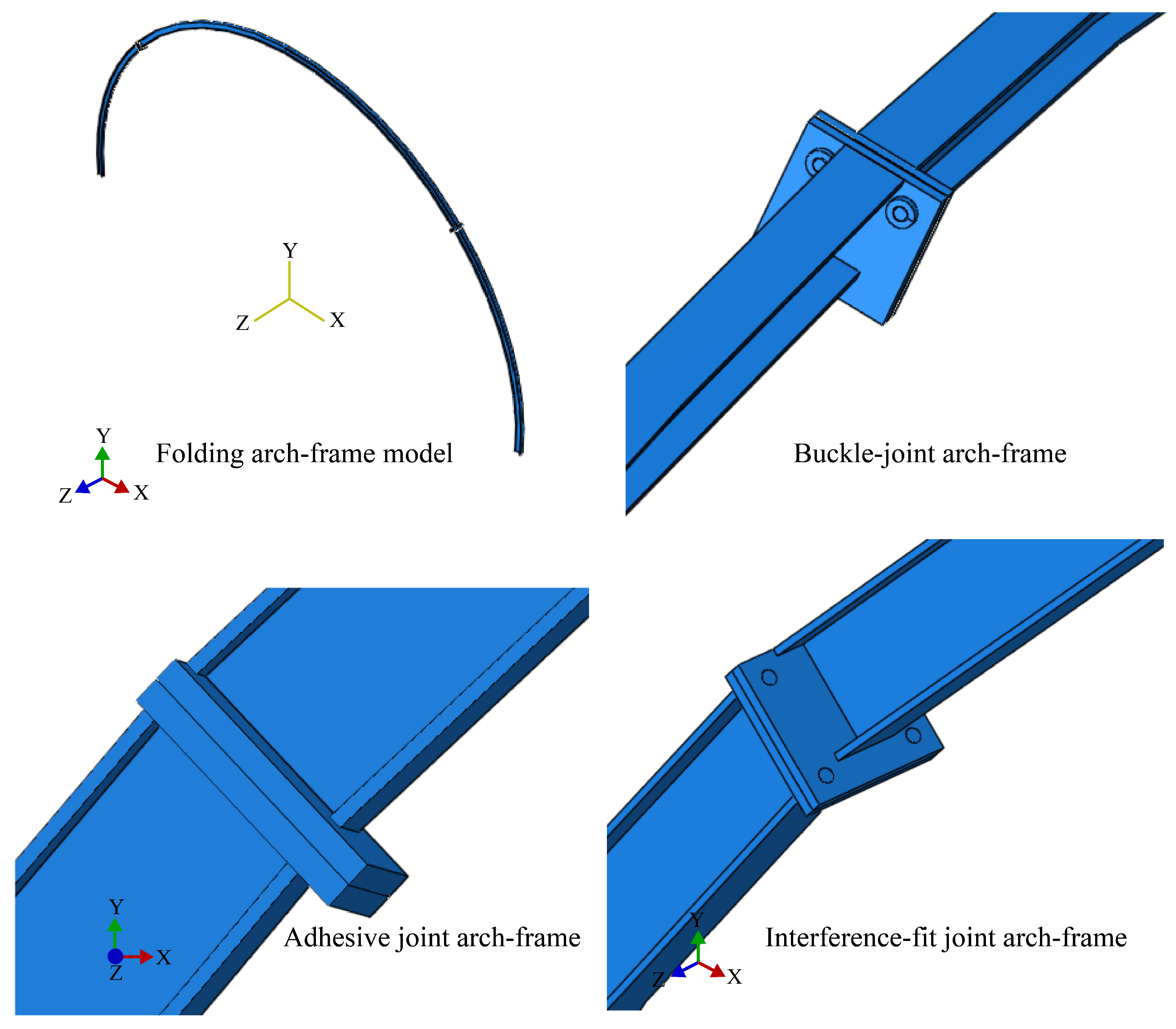
Figure 4.
Displacement (mm) of steel arch.

Figure 5.
Main stress (MPa) analysis of steel arches with different connection forms.

Figure 6.
Local principal stress (MPa) of buckle joints.

Figure 7.
Local principal stress (MPa) of an interference-fit joint.

Table 1.
Material parameters of the model I-beam.
| Material Name | Elastic Modulus E (MPa) | Poisson’s Ratio μ | Yield Strength (MPa) |
|---|---|---|---|
| I-beam 16 | 210 × 103 | 0.3 | 235 |
Table 2.
Comparison of mechanical properties of folding arches with different joint forms.
| Joint Form | Buckle | Adhesive | Interference-Fit |
|---|---|---|---|
| Vertical displacement of arches (mm) | 70.6 | 70.4 | 70.5 |
| Maximum compressive stress of an arch frame (MPa) | 51.6 | 74.9 | 43.9 |
| Maximum tensile stress of an arch frame (MPa) | 34.8 | 28.2 | 83.4 |
| Maximum shear stress of an arch frame (MPa) | 86.4 | 103.1 | 127.3 |
| Maximum shear stress at the joint (MPa) | 218 | 103.1 | 259.6 |
Table 3.
Quality statistics of unmanned arch erection and manual arch erection.
| No. | Deviation in Spacing from the Previous Arch Frame (mm) | Lateral Position Deviation (mm) | Inclination (°) | |||
|---|---|---|---|---|---|---|
| Unmanned Arch Erection | Manual Arch Erection | Unmanned Arch Erection | Manual Arch Erection | Unmanned Arch Erection | Manual Arch Erection | |
| 1 | 41 | 19 | 6 | 3 | 0.7 | 0 |
| 2 | 14 | 30 | 10 | 4 | 0.3 | 0.4 |
| 3 | 60 | 22 | 8 | 10 | 0.7 | 0 |
| 4 | 6 | 30 | 12 | 2 | 0.8 | 0.8 |
| 5 | 27 | 31 | 8 | 16 | 0.2 | 0 |
| 6 | 42 | 27 | 12 | 19 | 0.2 | 0.2 |
| 7 | 29 | 49 | 18 | 0 | 0.8 | 0.4 |
| 8 | 15 | 40 | 4 | 16 | 0.7 | 0.3 |
| 9 | 27 | 19 | 6 | 17 | 0 | 0.6 |
| 10 | 54 | 34 | 12 | 18 | 0.7 | 0.7 |
| 11 | 10 | 7 | 11 | 11 | 0.9 | 0.5 |
| 12 | 47 | 13 | 4 | 18 | 0.9 | 0.2 |
| 13 | 45 | 11 | 18 | 7 | 0.7 | 0.8 |
| 14 | 65 | 3 | 1 | 3 | 0.9 | 0.7 |
| 15 | 10 | 22 | 3 | 11 | 0.7 | 0.6 |
| 16 | 31 | 24 | 7 | 8 | 0.1 | 0 |
| 17 | 40 | 42 | 2 | 5 | 0.2 | 0.3 |
| 18 | 65 | 31 | 12 | 14 | 0.2 | 0.8 |
| 19 | 44 | 6 | 7 | 9 | 0.3 | 0.2 |
| 20 | 42 | 43 | 21 | 17 | 1.2 | 0.6 |
| 21 | 59 | 43 | 19 | 13 | 0.3 | 0.7 |
| 22 | 27 | 17 | 6 | 17 | 0.7 | 0.7 |
| 23 | 46 | 22 | 6 | 18 | 1.6 | 0.8 |
| 24 | 45 | 19 | 9 | 14 | 0.7 | 0.8 |
| 25 | 52 | 40 | 6 | 12 | 0.3 | 0.3 |
| 26 | 22 | 0 | 13 | 9 | 0.3 | 1.4 |
| 27 | 53 | 9 | 10 | 8 | 0.5 | 0.3 |
| 28 | 16 | 13 | 8 | 3 | 0.2 | 0.4 |
| 29 | 3 | 11 | 14 | 15 | 0.8 | 0.4 |
| 30 | 43 | 10 | 4 | 2 | 0.2 | 0.8 |
| 31 | 26 | 1 | 7 | 14 | 0.8 | 0.1 |
| 32 | 35 | 40 | 19 | 16 | 0.2 | 0.7 |
| 33 | 34 | 49 | 4 | 16 | 0.3 | 0 |
| 34 | 59 | 49 | 7 | 15 | 0.1 | 0.7 |
| 35 | 43 | 16 | 19 | 4 | 0.4 | 0.6 |
| 36 | 45 | 49 | 7 | 5 | 0.1 | 0.1 |
| 37 | 50 | 25 | 7 | 2 | 0.7 | 0.2 |
| 38 | 31 | 36 | 12 | 3 | 0.1 | 0 |
| 39 | 64 | 21 | 16 | 11 | 0.4 | 0.3 |
| 40 | 36 | 19 | 2 | 17 | 0.8 | 0.6 |
| 41 | 64 | 12 | 12 | 17 | 0.6 | 0.1 |
| 42 | 69 | 39 | 5 | 5 | 0.4 | 0.3 |
| 43 | 40 | 20 | 2 | 19 | 0.5 | 0.1 |
| 44 | 64 | 24 | 13 | 6 | 0.4 | 0.2 |
| 45 | 18 | 48 | 1 | 6 | 0.5 | 0.3 |
| 46 | 67 | 8 | 7 | 4 | 0.5 | 0.1 |
| 47 | 7 | 11 | 4 | 8 | 0.9 | 0.3 |
| 48 | 64 | 29 | 18 | 18 | 0.6 | 0.8 |
| 49 | 49 | 47 | 8 | 8 | 0.2 | 0.9 |
| 50 | 61 | 0 | 10 | 15 | 0.5 | 0.9 |
| Average value | 40 | 25 | 9 | 11 | 0.5 | 0.4 |
| Pass rate | 100% | 100% | 100% | 100% | 96% | 98% |
Table 4.
Comparison of process time between unmanned arch erection and manual arch erection.
| Process Name | Unmanned Arch Erection Construction Duration (min) | Process Name | Manual Arch Erection Construction Duration (min) |
|---|---|---|---|
| Preparation time | 20 | Preparation time | 20 |
| Arch frame installation | 25 | Arch frame installation | 45 |
| Drilling, installation, and grouting of locking anchor pipes | 15 | Drilling, installation, and grouting of locking anchor pipes | 25 |
| Welding steel mesh and connecting bars | 20 | Welding steel mesh and connecting bars | 20 |
| Equipment demobilization | 10 | Equipment demobilization | 10 |
Disclaimer/Publisher’s Note: The statements, opinions and data contained in all publications are solely those of the individual author(s) and contributor(s) and not of MDPI and/or the editor(s). MDPI and/or the editor(s) disclaim responsibility for any injury to people or property resulting from any ideas, methods, instructions or products referred to in the content. |
© 2024 by the authors. Licensee MDPI, Basel, Switzerland. This article is an open access article distributed under the terms and conditions of the Creative Commons Attribution (CC BY) license (https://creativecommons.org/licenses/by/4.0/).
Share and Cite
MDPI and ACS Style
Huang, C.; Li, S.; Li, D.; Li, W.; Yao, T.; Xiao, Y. Mechanical Properties of Folding Arch Frame Joints for Unmanned Arch Erection. Buildings 2024, 14, 1480. https://doi.org/10.3390/buildings14051480
AMA Style
Huang C, Li S, Li D, Li W, Yao T, Xiao Y. Mechanical Properties of Folding Arch Frame Joints for Unmanned Arch Erection. Buildings. 2024; 14(5):1480. https://doi.org/10.3390/buildings14051480
Chicago/Turabian StyleHuang, Changfu, Shaohua Li, Dewu Li, Wenbing Li, Tiejun Yao, and Yong Xiao. 2024. "Mechanical Properties of Folding Arch Frame Joints for Unmanned Arch Erection" Buildings 14, no. 5: 1480. https://doi.org/10.3390/buildings14051480
Note that from the first issue of 2016, this journal uses article numbers instead of page numbers. See further details here.