Article

Compliance Assessment of the Spatial Averaging Method for Magnetic Field Leakage from a Wireless Power Transfer System in Electric Vehicles

1
Department of Electrical and Mechanical Engineering, Nagoya Institute of Technology, Nagoya 466-8555, Japan
2
Center of Biomedical Physics and Information Technology, Nagoya Institute of Technology, Nagoya 466-8555, Japan
*
Author to whom correspondence should be addressed.
Appl. Sci. 2024, 14(7), 2672; https://doi.org/10.3390/app14072672
Submission received: 28 February 2024 / Revised: 13 March 2024 / Accepted: 20 March 2024 / Published: 22 March 2024
(This article belongs to the Special Issue Trends and Prospects in Applied Electromagnetics)

Abstract

:
Wireless power transfer (WPT) via magnetic resonance offers efficient electrical power transfer, making it an increasingly attractive option for charging electric vehicles (EVs) without conventional plugs. However, EV charging requires a transfer power in order of kW or higher, resulting in a higher-leaked magnetic field than conventional wireless systems. The leaked magnetic field is nonuniform, and the assessment in terms of the limit prescribed in the guideline is highly conservative because it assumes that a person standing in free space is exposed to a uniform field. In such cases, an assessment should be performed using the limits of the internal electric field, as it is more relevant to the adverse health effects, whereas its evaluation is time-consuming. To mitigate this over-conservativeness, international product standards introduce a spatial averaging method for nonuniform exposure assessment. In this study, we investigate assessment methods, especially for measurement points of nonuniform magnetic field strength leaked from the WPT system. Various spatial averaging methods are correlated with the internal electric field derived from electromagnetic field analysis using an anatomically based human body model. Our computational results confirm a good correlation between the spatially averaged magnetic and internal electric fields. Additionally, these methods provide an appropriate compliance assessment with the exposure guidelines. This study advances our understanding of the suitability of spatial averaging methods for nonuniform exposure and contributes to the smooth assessment in WPT systems.

1. Introduction

Wireless power transfer (WPT) technology relies on the principle of magnetic resonant coupling between two coils, enabling the efficient transmission of electrical power over distances ranging from several tens of centimeters to a few meters [1,2,3,4,5]. This technology is increasingly gaining interest as a streamlined method for charging electric vehicles (EVs) without conventional plugs [6]. However, EV charging requires a significant amount of power, reaching several kilowatts, leading to the leakage of strong electromagnetic fields during charging [7]. Concerns about the potential adverse effects for WPT continue to exist, which require further investigation [8].
The International Commission on Non-Ionizing Radiation Protection (ICNIRP) [9,10,11] and IEEE International Committee on Electromagnetic Safety Technical Committee 95 [12,13] have published international guidelines and standards (hereafter referred to as “guidelines”) limiting exposures to electromagnetic fields for human protection. These guidelines were designed to protect humans from electrostimulation up to 5–10 MHz and heating above 100 kHz. In these guidelines, the operational threshold for adverse health effects is identified [9,10,11,12]. A reduction (safety) factor [11], basic restriction (BR) [9,10], or dosimetric reference limit [12] (hereafter referred to as BR), which is the electrical quantity related to the health effect, is then derived. For practical assessment, permissible external field strength (hereafter referred to as reference level (RL)) [10] or exposure RL is derived under a worst-case exposure scenario. In the IEEE C95.6-2002 standard [13], the RL, permissible external field strength is derived based on an analytical formula using homogeneous ellipsoidal induction models, which differ between the limb and trunk [13].
International standards for product conformity [14], such as International Electrotechnical Commission (IEC) 61980-1 [15], SAE J2954 [16], and ISO 19363 [17], have been established for WPT in EVs, all of which consider the international exposure guidelines. Computational assessments using human body models have been widely used, including international standardization, because in vivo measurements cannot be performed for the assessment of an induced electric field (e.g., IEC 61980 and SAE J2954). Numerous studies have pointed out the limitation of RL in highly nonuniform environments, such as those emitted from WPT [18,19,20,21]. These results consistently showed that, although the spatial peak magnetic fields at the human body parts exceeded RL, the internal electric fields in the human body were one or two orders of magnitude smaller than the limit of induced physical quantities (see Section 2).
The IEC Technical Committee 106 is an international standardization body that provides compliance assessment methods corresponding to international exposure guidelines/standards. The spatially averaged method defined in IEC 62110 was discussed and extended to assess nonuniform fields [22]. The spatial averaging for the magnetic field strength measured (computed) at some points confirms compliance with RL. The assessment of the spatial averaging method is also included in IEC TR 62905 and IEC PAS 63184 [23,24], wherein various measurement points inside and outside the vehicle are considered.
Several studies have evaluated the location of the magnetic field measurement point in realistic vehicle models [25,26,27,28,29,30,31,32]. As summarized in Section 2, recent studies conducted measurements at designated test points near the vehicle and within the driver’s seat. However, the relationship between these measurement points and the internal electric field, which should be assessed computationally, has not been clarified. Appropriate measurement locations that can effectively capture their coupling quantities have not been considered in the current product standards. In addition, the exposure scenarios are different for different studies, and thus, straightforward comparison was difficult.
At the IEC JWG 63184 meeting, the methods for assessing EV WPT are discussed. For practical assessment, the correlation between the spatially averaged magnetic field strength and permissible exposure levels defined by ICNIRP and IEEE is required for justification. However, in [18], this correlation was only discussed between the spatially averaged magnetic field value and internal electric fields assuming a standing posture. Additionally, there has been no study discussed measurement point for compliance assessment to relate the induced electric field and magnetic field in the cabin for realistic postures such as those of a driver situated inside the vehicle. Scientific data considering the scenarios discussed in the standardization meeting would provide insight for reliable measurement procedure.
This study aims to clarify the measurement (evaluation) points for nonuniform magnetic field strength leaked from the WPT system for a realistic EV cabin environment. To provide the rationale for the averaging points, we considered different spatial averaging methods to correlate with the internal electric field, which is the metric in the human exposure guidelines.

2. Related Studies

2.1. Evaluation of Leaked Magnetic Field

Laakso validated the leaked magnetic field from WPT coil for a simplified vehicle model [33]. Che et al. evaluated the conformity at several measurement points inside and outside the vehicle according to the electromagnetic field test procedure in SAE J2954 [25]. Mohamed et al. conducted testing on a WPT system installed in a heavy-duty electric shuttle [26]. El-Shahat evaluated the external magnetic field from different WPT coils and derive a distance compliant with the ICNIRP guidelines [27]. The magnetic field inside and outside the vehicle cabin has been measured [28]. The magnetic field leaked from the wireless power transfer system is analyzed for heavy duty vehicles [29].

2.2. Computational Dosimetric Study for EV WPT Systems

Numerous compliance assessments have been conducted for exposure resulting from the WPT system. For example, Laakso et al. evaluated the compliance of three human body models beside a vehicle at different human–vehicle angles [18]. Shimamoto et al. considered various postures, such as lying on the ground with the right arm extended toward the coils, to consider worst-case scenarios [19]. Wen et al. predicted the magnetic field leakage generated from parallel WPT systems operating with a phase difference, including assessing the internal electric field and the specific absorption rate in a human body near these systems [34]. De Santis et al. investigated the influence of vehicle materials and human body posture on compliance assessment in compact EVs [21,35,36]. Liorni et al. developed and validated a numerical model of inductive power transfer systems in a heavy vehicle and compared the exposure of passengers in public vehicles with light vehicles [37]. Lan et al. investigated the effect of ferrite materials, such as loudspeakers and electromotors, on the magnetic field distribution inside the vehicle [38]. Wang et al. conducted uncertainty analysis on dosimetric measures, i.e., quantified the impact of different parameters on power absorption [39]. In most studies, the number of scenarios and conditions considered were less than 25 cases, except for [18] (144 cases) and [34] (120 cases). To discuss the measurement methods in the product safety standardization, enough number of cases should be considered to ensure the safety based on the human exposure guidelines [9,10,11].

2.3. Exposure Assessment Method for Nonuniform Magnetic Field

Several studies have investigated methodologies for a realistic and comprehensive assessment of nonuniform magnetic fields resulting from the WPT system. Wake et al. derived coupling factors for EVs and home appliances with WPT to assess compliance with BR equivalently in terms of the measured external field strengths. They also compared these factors across multiple institutions [40]. Chakarothai et al. proposed an experimental approach for determining the internal electric field without prior knowledge of the WPT system’s design using measured magnetic near-field data [41]. Miwa et al. assessed adherence to international standards using a coupling factor, focusing on the exposure of human subjects positioned in both the driver’s seat and the rear passenger compartment of a vehicle [20]. Park et al. examined WPT using the minimum accessible distances in compliance with RL in instances of proximity exposure, considering various exposure patterns [42]. Ahn et al. proposed an improved coupling factor calculation method for removing computational artifacts to achieve uniform assessment results in various human body models [43]. These studies assessed compliance procedures under these specific conditions, making it challenging to make overarching generalizations.

2.4. Comparison of Exposure Assessment in Human Exposure Inside and Outside the Vehicle

As listed in above subsections, several studies have been conducted to assess the relationship between the leaked magnetic field and induced electric field. The frequency for WPT has been now standardized at 85 kHz [16]. The limit of induced electric field (BR) and external magnetic field (RL) in the international guidelines are (11.5 V/m, 21 A/m) and (17.8 V/m, 163 A/m) for ICNIRP and IEEE, respectively. Thus, their relationship and overconservativeness are assessed in different manners. Table 1a,b lists the key computational results in previous studies for scenarios outside and inside the vehicles. In these studies, the number of vehicle models was one. For proper comparison, the coupling factor [44] was derived.

3. Models and Methods

Our computational approach to compute the external magnetic field and induced electric field (Section 3.3), as well as human body models (Section 3.1), is the same as in our previous studies [19,20]. Our approach is briefly summarized below.

3.1. Human Body Models

In this study, we employed an anatomical human body model TARO developed at the National Institute of Information and Communications Technology (NICT) [45]. The height and mass of the model is 173.2 cm and 65 kg, respectively. The number of tissues considered in TARO is 51. The voxel resolution of the human model was set at 2.0 mm. Two distinct postures were considered for the models, including the original standing posture and a seated posture simulating a driver’s position, as illustrated in Figure 1. The seated model was created utilizing software provided by NICT [46]. The posture of the driving seat has been generated considering [47].

3.2. Exposure Scenarios

SAE J2954 [16] recommends three standard power levels: WPT1 at 3.7 kW, WPT2 at 7.7 kW, and WPT3 at 11 kW. In this study, the WPT system integrated into the vehicle adhered to the specifications outlined in SAE J2954 at 3.7 kW (WPT1). Note that the computational results are scalable to other transfer power. Figure 2 shows a detailed schematic of the WPT coils. The transmitting coil was rectangular, with a length of 580 mm and a width of 420 mm following to SAE J2954 [16]. It consisted of 15 turns, with a width of 3 mm. The receiving coil was a 320 mm square. It equipped with 20 turns and had a width of 2 mm. The distance between the top of the transmitting coil and the bottom of the receiving coil was 150 mm, which is in accordance with WPT1. The two coils were assumed to be composed of a perfect conductor for conservative assessment. The thicknesses of shield plate and ferrite core are 2 mm and 3 mm, respectively. The transmitter and receiver current sources I1 and I2, were set to 16 and 17 A, respectively, to achieve a transmitting power of 3.7 kW. The phase difference of the currents between the transmitting and receiving coils was 90°. The frequency of the WPT system was 85 kHz. The following relationship holds for current source I1 and I2 [48].
I 2 j L 1 L 2 I 1
where L1 and L2 represent the inductance of the transmitter and receiver coils, respectively. Note that the assumption of coil material as perfect conductor would result in a slightly larger leaked magnetic field of 1% or less, under the condition that the transmitting power is fixed at 3.7 kW [49].
Figure 3 shows a vehicle model and two realistic exposure scenarios for the assessment. The simplified vehicle’s geometry was developed using the Toyota Motor Corporation’s Prius model and was positioned in free space. Note that the effect of the ground and surrounding objects marginally influences the magnetic field where the quasi-magnetostatic approximation is valid. The receiving coil was positioned beneath the center of the vehicle body. Misalignment between the receiving and transmitting coils were chosen as 75 mm and 100 mm in the x and y directions, respectively, following SAE J2954 [16]. We considered two vehicle body materials, including iron and carbon fiber-reinforced plastic (CFRP). The relative permittivity, permeability, and conductivity values for iron and CFRP were 1, 4000, and 10.3 × 10⁶ S/m and 1, 1, and 0.25 × 10⁶ S/m, respectively. The thicknesses of iron and CFRP were 0.5 and 2.0 mm, respectively. In this study, two scenarios discussed in IEC JWG 63184 were considered. In the first scenario, a human body model stands outside the vehicle body where the highest exposure to the magnetic field from the WPT system was computed. Meanwhile, the human body in the second scenario was located in the driver’s seat, where the distance from the floor to the driver’s buttocks was 200 mm. Note that the position of the human body in the vehicle cabin has been standardized for such purposes [23,24,50].

3.3. Computational Methods

In a frequency range lower than the MHz range, it is feasible to utilize a quasi-static approximation to calculate the internal electric field within biological tissue [51,52,53]. In the regime in which the quasi-static approximation is valid, the conduction current in the body is dominant rather than the displacement current. This assumption causes the external electromagnetic fields to be decoupled into electric and magnetic fields. Additionally, the external magnetic field can be assumed to be unperturbed by the presence of the human body.
The magnetic field leaked from the WPT system was computed using a commercial electromagnetic simulator (HFSS, Ver. 2023 (R1), ANSYS, Canonsburg, PA, USA) without considering the human body model. The magnetic field was extracted from HFSS in several rectangular volumes with a grid resolution of 50 mm × 50 mm × 50 mm. These data were used to construct a magnetic vector potential with a grid resolution of 2 mm × 2 mm × 2 mm.
The next step involves computing the internal electric field by substituting the vector potential distribution into an electromagnetic solver developed at the Nagoya Institute of Technology [54]. The solver used to compute the internal electric field is based on the scalar-potential finite-difference (SPFD) method [55].
The SPFD method discretizes the human model using cubical voxels and generates simultaneous linear equations for all contacts, with the electric scalar potential as an unknown variable. The internal electric field is then computed through matrix calculation. To accelerate computation, the geometric multigrid method is employed as a preconditioner [54]. In the SPFD method, tissue conductivities in the human body model are taken from a technical report in [56], which is consistent with [57,58]. In addition, the leaked magnetic field from WPT coil has been validated for the simplified vehicle model with same computational approach [33]. Our computational approach here has been validated by intercomparison [40].

3.4. Compliance Assessment Procedure

Several product assessment standards and technical reports define spatial averaging methods for exposure to nonuniform magnetic fields. The spatial averaging method involves averaging the magnetic field strength measured (computed) at specific spatial points. For instance, IEC TR 62905 [23] specified the measurement of magnetic fields on a plane located 20 cm from three points at different heights (0.5, 1, and 1.5 m) for humans standing by the side of the vehicle. This reference is derived from IEC 62110 [22]. IEC PAS 63184 [24] extended this by including the closest accessible point to the three points. IEC PAS 63184 also outlined the measurement of the magnetic field at the center position of the floor flat surface and the points at the center position of the headrest, backrest, and seat for sitting on the driver’s seat.
We outlined three definitions for each posture, as shown in Table 2 and Figure 4. In Definition 1 for outside the vehicle, the measurement point was defined at the heights of 0.5, 1.0, and 1.5 m from the ground based on IEC TR 62905. In Definition 1 for inside the vehicle, the measurement heights are 0.5, 1.0, and 1.2 m from the floor, corresponding to the cushion, chest, and head of the seat, respectively. In Definition 2, the closest accessible point was incorporated into Definition 1 based on IEC PAS 63184, considering the foot. In Definition 3, the measurement point was defined at the heights of the closest accessible point and two points, each 25 cm higher from it, aiming to be more stringent than Definitions 1 and 2. The measurement points of 0.35, 0.6, 1.0, and 1.2 were defined along a 15-degree angle of the seat to align with the central axis of the human body, considering the human body model sits in the driver’s seat in a realistic posture.
Using these definitions, we calculated the spatial average of the magnetic fields (Have) and compared them with the limit prescribed in the exposure guidelines [7,9]. In this study, we compared the ratio of Have to RL (HRL) and that of the maximum internal electric field (Emax) to BR (EBR). The spatial averaged method was evaluated using the following equation:
a c = ( E max E BR ) / ( H ave H RL )
where ac represents an index of the conformity ratio of external magnetic and internal electric fields to the guideline. If ac is less than 1, it indicates that the assessment based on the spatial average of the magnetic field in the corresponding definition is more stringent than that based on the maximum electric field.
The magnetic field strength was computed in the domain averaged over 100 cm2, assuming the 100 cm2 loop antenna prescribed in the IEC standard [44,59]. This averaging area was considered as a postprocessing step for the computed field distribution.
In the evaluation of the internal electric field in anatomical models, the skin-to-skin contact is not negligible [12], which is inherent to the discretization of a real human model into a finite-resolution model. This computational weakness results in a higher internal electric field at the corresponding part. Therefore, the electric field at skin-to-skin contact was excluded, as mentioned in IEEE C95.1 standard [12]. Different postprocessing method has been proposed to reduce numerical artifacts. This study employed the peak voxel value for 99.9th percentile values for body parts in the anatomical human body as a conservative approach. We express the external magnetic and internal electric fields in root-mean-square values for comparison with international standards.

4. Results

In this section, the internal electric field computation has been evaluated for exposure scenarios in which the human stands outside and sits inside the vehicle (Section 4.1 and Section 4.2). Then, we have evaluated the averaging method of magnetic field for the scenario outside (Section 4.3) and inside the vehicle (Section 4.4 and Section 4.5). For the exposure scenario inside the vehicle, the correlation between the averaged magnetic field and internal electric field is evaluated to provide the scientific rationale for the measurement point in the standardization.

4.1. Distribution of Magnetic Field Outside and Inside the Vehicle

Figure 5 and Figure 6 show the magnetic field strength distributions outside and inside the vehicle, as viewed from the side of the vehicle, for different vehicle body materials. The computational domain is illustrated in Figure 3. As shown in Figure 5, there was no significant difference in the distribution between iron and CFRP outside the vehicle. In contrast, the magnetic field inside the vehicle was scarcely distributed for a body made of iron due to the shielding effect shown in Figure 6. In the case of the CFRP body, the magnetic field generated by the WPT system leaks directly into the cabin beneath the floor.

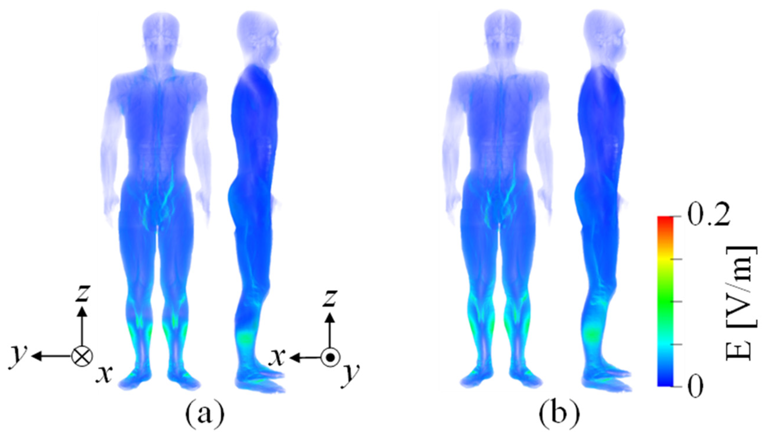
4.2. Internal Electric Field in the Human Body

Figure 7 and Figure 8 show the distributions of the internal electric field in the human body models corresponding to outside and inside the vehicle for different vehicle body materials, respectively. As shown in Figure 7, the maximum internal electric field was observed in the lower limb near the WPT system for both materials when humans were standing outside the vehicle. The 99.9th percentile values of the electric field were 0.05 V/m. Figure 8 shows that the electric field was primarily induced in the torso and head due to the magnetic field leakage from the window, albeit with a 99.9th percentile value of 1.6 × 10⁻³ V/m. In contrast, a high internal electric field was distributed in the buttocks for the CFRP body, with the 99.9th percentile value of 0.20 V/m.

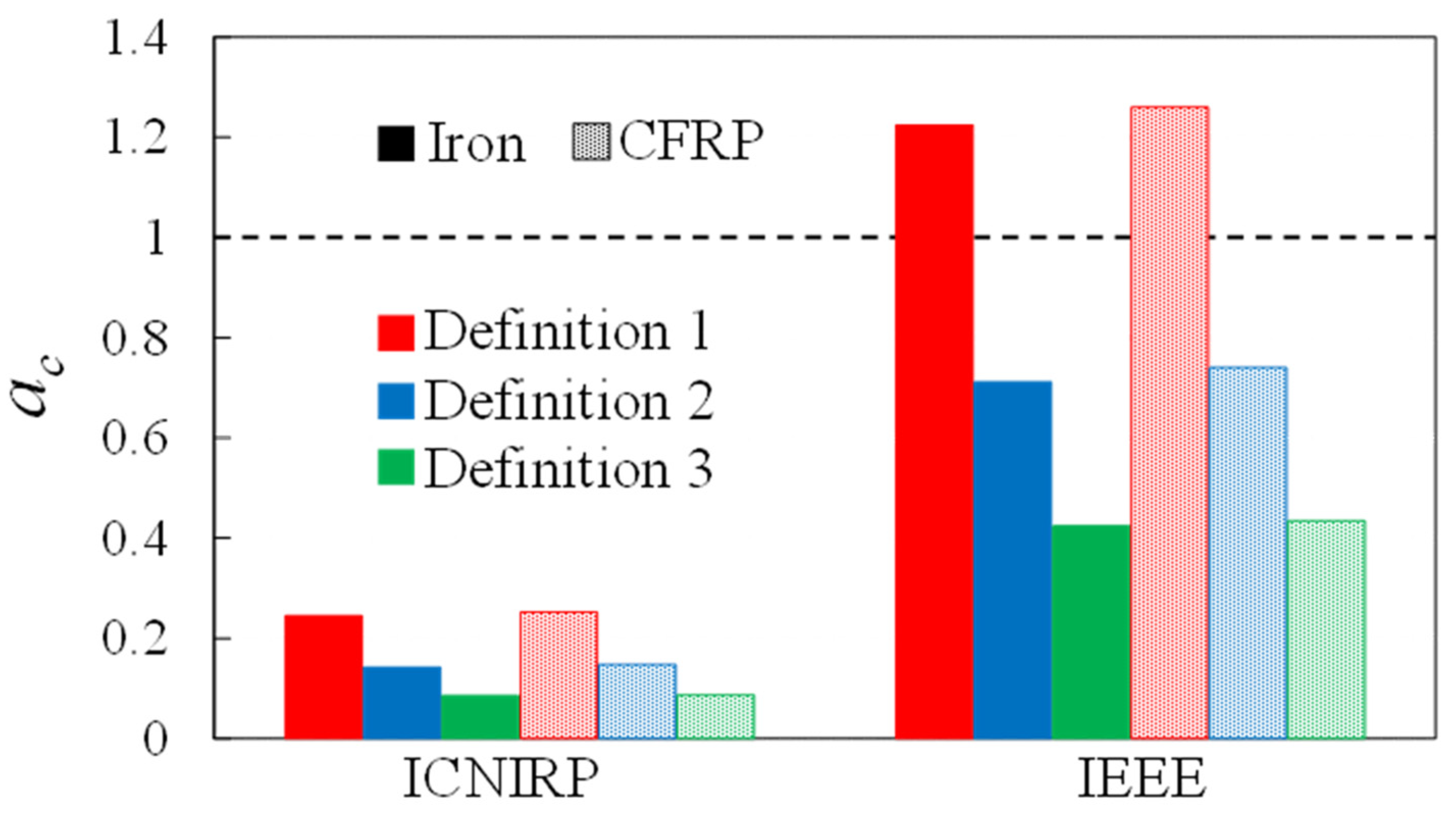
4.3. Assessment with Spatial Averaged Magnetic Field Outside the Vehicle

The relationship between the external magnetic and internal electric fields was evaluated outside the vehicle [18]. The averaged magnetic field strength (Have) was calculated based on the measurement points and averaging scenario defined in Table 2. Table 3 presents the magnetic field strength outside the vehicle at the measurement points and Have for vehicle body with different materials. As shown in Table 3, the magnetic field strengths for different materials are consistent. Figure 9 shows the conformity assessment in each definition against the ICNIRP guidelines and IEEE standard in terms of ac outside the vehicle. As shown in the figure, the stringer assessment methods were in the order of Definitions 3, 2, and 1 because a high magnetic field was distributed near the ground. All definitions exhibited a conservativeness with more than a margin of a factor of four with respect to the ICNIRP guidelines, whereas only Definition 1 was an unconservative assessment for the IEEE standard. The magnetic field limits for the ICNIRP guidelines and IEEE standard are 21 and 163 A/m for public exposure.

4.4. Correlation between Emax and Have Inside the Vehicle Made of CFRP

The average of three or more measurement points can provide a reliable estimate of the internal electric field when the human body model stands by the side of the vehicle [18]. However, we did not consider a scenario in which a person sat in the driver’s seat [18]. We evaluated the relationship between the external magnetic and internal electric fields for different vehicle seat positions. The seat position was varied by ys = ±100 mm (in 20-mm increments) in the y-direction based on the adjustment range of a typical seat. This section focuses on the CFRP body since the magnetic field was almost shielded for an iron body.
Figure 10a shows the relationship between the average magnetic field strength within the volume containing the human body model and the internal electric field. The average magnetic field was determined by calculating the arithmetic mean of the absolute magnetic field values over the whole body. The correlation has been evaluated in terms of coefficient of determination (R2) [60,61] assuming the linear relationship. If they are correlated linearly, the induced electric field can be equivalently evaluated in terms of average magnetic field without detailed computation. There was a strong correlation between the whole-body Have and the internal electric field. Figure 10b shows the relationship between the magnetic field strength at a single measurement point defined in Table 2 and the internal electric field. As shown in Figure 10b, good correlations were observed at specific points, such as 0.1, 0.5, and 1.2 m. However, there was no consistent trend for the other measurement points. Figure 10c shows the relationship between the average magnetic and internal electric fields at three or four points outlined for each definition. As shown in Figure 10c, the average magnetic field reasonably correlates with the internal electric field across all definitions. In Definitions 2 and 3, Emax reached its peak because the exposure area from the buttocks to the feet approaches a certain level when the seat is moved backward.

4.5. Assessment with Spatial Averaged Magnetic Field Inside the Vehicle

Table 4 presents the magnetic field strength inside the vehicle at the measurement points and Have for different materials (ys = 0). As shown in Table 4, the magnetic field strength within the iron body was two orders of magnitude lower than that within the CFRP body. Figure 11 shows the conformity assessment in each definition for the ICNIRP guidelines and IEEE standard in terms of ac inside the vehicle (ys = 0). As shown in the figure, all definitions in the case of the iron body exhibited a conservativeness with more than a margin of a factor of four with respect to the ICNIRP guidelines, whereas they were either comparable or unconservative with respect to the IEEE standard. In contrast, for the CFRP body, Definition 1 provided a level of protection equivalent to the ICNIRP guidelines. Definitions 2 and 3 displayed a conservativeness with more than a margin of a factor of 3.4 with respect to the ICNIRP guidelines. In the IEEE standard, Definitions 1 and 2 were unconservative, whereas Definition 3 exhibited a conservativeness with more than a margin of a factor of 1.2.
Figure 12 shows the assessment of each definition for compliance with the ICNIRP guidelines and IEEE standard using ac when the vehicle seat position was changed in the front–back direction (ys = ±100 mm). As shown in Figure 12, the variation in ac in the case of the iron body remained relatively insignificant due to the weak nonuniformity of the magnetic field distribution. In contrast, for the CFRP body, ac varied from approximately −0.1% to 3%, −27% to 36%, and −21% to 18% in Definitions 1, 2, and 3, respectively, regardless of the target guidelines. The variability in Definitions 2 and 3 is influenced by the observation that the variation in Have considering the measurement point at the lower limb is larger than that of Emax appearing at the buttocks. However, by adding a reduction factor smaller than two, such an effect of variations is sufficiently avoided.

5. Discussion

This study evaluated compliance assessment using the spatial averaging method as a scheme to evaluate human exposure to nonuniform fields at low frequencies. The evaluation index for this method was the spatially averaged magnetic field strength at three or four heights from the ground or floor and the internal electric field in the anatomical human model placed near or inside the vehicle.
As shown in Figure 5 and Figure 6, the distributions of the magnetic field were not significantly different between iron and CFRP outside the vehicle. However, the magnetic field was scarcely distributed for a body made of iron placed inside the vehicle. This is because the conductive chassis shields the magnetic field. In contrast, the magnetic field generated by the WPT system for a body made of CFRP leaks directly into the cabin beneath the floor. This resulted in a marginal difference in the internal electric field in the human body outside the vehicle because of the body material, but a significant difference inside the vehicle.
We calculated the magnetic field averaged over the heights defined in this study and compared it with the ICNIRP guidelines and IEEE standard in terms of ac. When ac is less than one, the BR would still be satisfied even with an increased coil output, provided that Have of the definition satisfies the RL. Laakso et al. reported a ratio of the internal electric field to the three-point average magnetic field strength of 0.20 V/A with three human body models at several angles outside the vehicle [18], which is close to 0.13 V/A obtained for a similar averaging definition in this study. These values are close but somewhat different from other studies (see Table 1), which is attributable to different postures and target areas discussed in previous studies. Note that the discussion here follows the discussion for the product safety standard (See Section 3.4). As shown in Figure 9, Definition 1 provided a conservative assessment of the ICNIRP guidelines with each body material. However, Definition 1 did not meet the requirements of the IEEE standard, whereas Definitions 2 and 3 were satisfied. This is because RL prescribed in the IEEE standard are relatively tolerant of a permissible external magnetic field. Using Definition 1 and following the ICNIRP guidelines, the maximum permissible transferred power for outside the vehicle made of iron and CFRP was 196 and 191 kW, respectively. Moreover, it was 884 and 871 kW using Definition 2 and the IEEE standard, respectively.
The whole-body Have, H at specific points, and three- or four-point Have provided good correlation for the scenario inside the vehicle, whereas no consistent trend was discernible for the other one-point measurement points (Figure 10). This can be attributed to the difficulty of capturing the electric field at a single point in a highly nonuniform environment with a realistic human body shape, such as the driver’s posture. Additionally, measuring the magnetic field over the volume of the human body is practically difficult. Therefore, the spatially averaged method is a good index to reasonably simplify the compliance assessment procedure inside the vehicle. As shown in Figure 11, all definitions for the iron body provided a sufficiently conservative assessment of the ICNIRP guidelines, whereas they were either comparable or unconservative with respect to the IEEE standard. In contrast, for the CFRP body, Definition 1 provided an equivalent level of protection in the ICNIRP guidelines. However, Definitions 1 and 2 did not meet the requirements of the IEEE standard, whereas Definition 3 met this requirement. When the vehicle seat position was changed in the front–back direction, the absolute changes in ac with respect to the ICNIRP guidelines were quite small, and the impacts on the conformity assessment were marginal (Figure 12). However, some reduction factors may need to be applied to Definition 1 for the iron body and Definition 3 for the CFRP body as they may not meet the IEEE standard. Even considering additional reduction factor, its magnitude is two, which is much smaller than the one order of magnitude or more, which is inherent to apply the RL in the exposure guidelines to nonuniform field exposure such as electric vehicle (Section 2). Although it is necessary to introduce an additional reduction factor for the IEEE standard, Definition 1 for the ICNIRP guidelines is satisfied. Using Definition 2, following the ICNIRP guidelines and IEEE standard, the maximum permissible transferred power for inside the vehicle made of CFRP was 62 and 241 kW, respectively.

6. Conclusions

The current product safety standards for WPT have not well considered the induced electric field in the human body for compliance assessment, which is more essential metric for human protection. Instead, the external magnetic field is used for practical purpose. To fill this gap, different scenarios were considered to correlate the induced electric field and external magnetic field in realistic scenarios. As the exposure scenarios can be limited around the vehicle cabin, different practical definitions were considered for assessment. From our finding, compliance assessment with exposure guidelines can be performed using appropriate definitions and averaging of magnetic field under realistic conditions discussed in the product safety standards. Spatial averaging of the magnetic field rather than single-point measurement is appropriate when considering the correlation with the internal electric field. In general, conservativeness is confirmed for most definitions considered here. If it is not satisfied, some adjustments should be introduced, such as an additional reduction factor of two to comply with the IEEE standard. Overconservativeness (by the one order of magnitude or more) may be avoided unlike the measurement of peak magnetic field for nonuniform field exposures.

Author Contributions

Conceptualization, A.H., S.K. and K.M.; methodology, K.M.; software, M.O. and K.M.; validation and formal analysis, M.O. and K.M.; investigation, K.M., M.O., S.K. and A.H.; writing—original draft preparation, M.O., A.H. and K.M.; writing—review and editing, K.M., M.O., S.K. and A.H.; visualization, M.O. and K.M.; supervision, A.H. All authors have read and agreed to the published version of the manuscript.

Funding

This research received no external funding.

Institutional Review Board Statement

Not applicable.

Informed Consent Statement

Not applicable.

Data Availability Statement

Raw data in this study are available based on reasonable request. The data are not publicly available due to the restricted use of anatomically based models.

Conflicts of Interest

The authors declare no conflicts of interest.

References

  1. Karalis, A.; Joannopoulos, J.D.; Soljačić, M. Efficient Wireless Non-Radiative Mid-Range Energy Transfer. Ann. Phys. 2008, 323, 34–48. [Google Scholar] [CrossRef]
  2. Vishnuram, P.; Panchanathan, S.; Rajamanickam, N.; Krishnasamy, V.; Bajaj, M.; Piecha, M.; Blazek, V.; Prokop, L. Review of Wireless Charging System: Magnetic Materials, Coil Configurations, Challenges, and Future Perspectives. Energies 2023, 16, 4020. [Google Scholar] [CrossRef]
  3. Mohamed, A.A.S.; Shaier, A.A.; Metwally, H.; Selem, S.I. An Overview of Dynamic Inductive Charging for Electric Vehicles. Energies 2022, 15, 5613. [Google Scholar] [CrossRef]
  4. Mohanarangam, K.; Palagani, Y.; Choi, J.R. Evaluation of Specific Absorption Rate in Three-Layered Tissue Model at 13.56 MHz and 40.68 MHz for Inductively Powered Biomedical Implants. Appl. Sci. 2019, 9, 1125. [Google Scholar] [CrossRef]
  5. Zhou, Y.; Liu, C.; Huang, Y. Wireless Power Transfer for Implanted Medical Application: A Review. Energies 2020, 13, 2837. [Google Scholar] [CrossRef]
  6. Chen, X.L.; Umenei, A.E.; Baarman, D.W.; Chavannes, N.; De Santis, V.; Mosig, J.R.; Kuster, N. Human Exposure to Close-Range Resonant Wireless Power Transfer Systems as a Function of Design Parameters. IEEE Trans. Electromagn. Compat. 2014, 56, 1027–1034. [Google Scholar] [CrossRef]
  7. Yang, Y.; El Baghdadi, M.; Lan, Y.; Benomar, Y.; Van Mierlo, J.; Hegazy, O. Design Methodology, Modeling, and Comparative Study of Wireless Power Transfer Systems for Electric Vehicles. Energies 2018, 11, 1716. [Google Scholar] [CrossRef]
  8. Brecher, A.; Arthur, M.D. Review and Evaluation of Wireless Power Transfer (WPT) for Electric Transit Applications; U.S. Department of Transportation: Washington, DC, USA, 2014. [Google Scholar]
  9. ICNIRP Guidelines for Limiting Exposure to Time-Varying Electric and Magnetic Fields (1 Hz to 100 kHz). Health Phys. 2010, 99, 818–836. [CrossRef]
  10. ICNIRP Guidelines for Limiting Exposure to Electromagnetic Fields (100 kHz to 300 GHz). Health Phys. 2020, 118, 483–524. [CrossRef]
  11. ICNIRP Principles for Non-Ionizing Radiation Protection. Health Phys. 2020, 118, 477–482. [CrossRef]
  12. IEEE Std C95.1-2019; IEEE Standard for Safety Levels with Respect to Human Exposure to Electric, Magnetic, and Electromagnetic Fields, 0 Hz to 300 GHz. IEEE: Piscataway Township, NJ, USA, 2019.
  13. IEEE C95.1-2005; IEEE Standard for Safety Levels with Respect to Human Exposure to Electromagnetic Fields, 0–3 kHz. Institute of Electrical and Electronics Engineers: Piscataway Township, NJ, USA, 2002; ISBN 0738133892.
  14. Grazian, F.; Shi, W.; Dong, J.; van Duijsen, P.; Soeiro, T.B.; Bauer, P. Survey on Standards and Regulations for Wireless Charging of Electric Vehicles. In Proceedings of the 2019 AEIT International Conference of Electrical and Electronic Technologies for Automotive (AEIT AUTOMOTIVE), Turin, Italy, 2–4 July 2019; pp. 1–5. [Google Scholar]
  15. IEC 61980-1; Electric Vehicle Wireless Power Transfer (WPT) Systems—Part 1: General Requirements. International Electrotechnical Commission: Geneva, Switzerland, 2020.
  16. SAE J2954; Wireless Power Transfer for Light-Duty Plug-In/Electric Vehicles and Alignment Methodology. SAE International: Warrendale, PA, USA, 2016.
  17. ISO 19363; Electrically Propelled Road Vehicles—Magnetic Field Wireless Power Transfer—Safety and Interoperability Requirements. International Organization for Standardization: Beijing, China, 2020.
  18. Laakso, I.; Hirata, A. Evaluation of the Induced Electric Field and Compliance Procedure for a Wireless Power Transfer System in an Electrical Vehicle. Phys. Med. Biol. 2013, 58, 7583–7593. [Google Scholar] [CrossRef]
  19. Shimamoto, T.; Laakso, I.; Hirata, A. In-Situ Electric Field in Human Body Model in Different Postures for Wireless Power Transfer System in an Electrical Vehicle. Phys. Med. Biol. 2015, 60, 163–173. [Google Scholar] [CrossRef]
  20. Miwa, K.; Takenaka, T.; Hirata, A. Electromagnetic Dosimetry and Compliance for Wireless Power Transfer Systems in Vehicles. IEEE Trans. Electromagn. Compat. 2019, 61, 2024–2030. [Google Scholar] [CrossRef]
  21. De Santis, V.; Giaccone, L.; Freschi, F. Influence of Posture and Coil Position on the Safety of a WPT System While Recharging a Compact EV. Energies 2021, 14, 7248. [Google Scholar] [CrossRef]
  22. IEC 62110; Electric and Magnetic Field Levels Generated by AC Power Systems—Measurement Procedures with Regard to Public Exposure. IEC: Geneva, Switzerland, 2009.
  23. IEC TR 62905; Exposure Assessment Methods for Wireless Power Transfer Systems. IEC: Geneva, Switzerland, 2018.
  24. IEC PAS 63184; Assessment Methods of the Human Exposure to Electric and Magnetic Fields from Wireless Power Transfer Systems—Models, Instrumentation, Measurement and Numerical Methods and Procedures (Frequency Range of 1 kHz to 30 MHz). IEC: Geneva, Switzerland, 2021.
  25. Che, K.; Yu, J.; Yang, P.; Wei, M.; Liu, S.; Li, D. Limits of Electromagnetic Environment for Electric Vehicle Wireless Power Transfer. In Proceedings of the Asia-Pacific Power and Energy Engineering Conference, APPEEC, Xi’an, China, 17–19 April 2021; IEEE Computer Society: Washington, DC, USA, 2021. [Google Scholar]
  26. Mohamed, A.S.A.; Meintz, A.; Schrafel, P.; Calabro, A. In-Vehicle Assessment of Human Exposure to EMFs from 25-kW WPT System Based on Near-Field Analysis. In Proceedings of the 2018 IEEE Vehicle Power and Propulsion Conference (VPPC), Chicago, IL, USA, 27–30 August 2018; pp. 1–6. [Google Scholar]
  27. El-Shahat, A.; Danjuma, J.; Abdelaziz, A.Y.; Abdel Aleem, S.H.E. Human Exposure Influence Analysis for Wireless Electric Vehicle Battery Charging. Clean Technol. 2022, 4, 785–805. [Google Scholar] [CrossRef]
  28. Liu, S.; Li, D.; Chen, C.; Jia, W.; Che, K.; Yu, J. Electromagnetic Field Safety Analysis of a 7.7 kW Wireless Power Transfer System for Electric Vehicles. Prog. Electromagn. Res. M 2023, 117, 1–12. [Google Scholar] [CrossRef]
  29. David, A.; Tiemann, M.; Clemens, M.; Schmuelling, B. Magnetic Field Analysis of 50 kW Wireless Power Transfer System for Heavy Duty Vehicles. IEEE Trans. Magn. 2023, 60, 3306809. [Google Scholar] [CrossRef]
  30. Park, S.W. Influence of Fields and SAR Evaluation for 13.56 MHz EV Resonance-Based Wireless Power Charging Systems. Microw. Opt. Technol. Lett. 2017, 59, 937–941. [Google Scholar] [CrossRef]
  31. Elnail, K.E.I.; Huang, X.; Xiao, C.; Tan, L.; Haozhe, X. Core Structure and Electromagnetic Field Evaluation in WPT Systems for Charging Electric Vehicles. Energies 2018, 7, 1734. [Google Scholar] [CrossRef]
  32. Hirata, A.; Diao, Y.; Onishi, T.; Sasaki, K.; Ahn, S.; Colombi, D.; De Santis, V.; Laakso, I.; Giaccone, L.; Wout, J.; et al. Assessment of Human Exposure to Electromagnetic Fields: Review and Future Directions. IEEE Trans. Electromagn. Compat. 2021, 63, 1619–1630. [Google Scholar] [CrossRef]
  33. Laakso, I.; Hirata, A.; Fujiwara, O. Computational Dosimetry for Wireless Charging of an Electrical Vehicle. Int. Symp. Electromagn. Compat. 2014, 202–205. [Google Scholar]
  34. Wen, F.; Huang, X.L. Human Exposure to Electromagnetic Fields from Parallel Wireless Power Transfer Systems. Int. J. Environ. Res. Public Health 2017, 14, 157. [Google Scholar] [CrossRef]
  35. De Santis, V.; Giaccone, L.; Freschi, F. Chassis Influence on the Exposure Assessment of a Compact EV during WPT Recharging Operations. Magnetochemistry 2021, 7, 25. [Google Scholar] [CrossRef]
  36. De Santis, V.; Campi, T.; Cruciani, S.; Laakso, I.; Feliziani, M. Assessment of the Induced Electric Fields in a Carbon-Fiber Electrical Vehicle Equipped with a Wireless Power Transfer System. Energies 2018, 11, 684. [Google Scholar] [CrossRef]
  37. Liorni, I.; Bottauscio, O.; Guilizzoni, R.; Ankarson, P.; Bruna, J.; Fallahi, A.; Harmon, S.; Zucca, M. Assessment of Exposure to Electric Vehicle Inductive Power Transfer Systems: Experimental Measurements and Numerical Dosimetry. Sustainability 2020, 12, 4573. [Google Scholar] [CrossRef]
  38. Lan, J.; Hirata, A. Effect of Loudspeakers on the in Situ Electric Field in a Driver Body Model Exposed to an Electric Vehicle Wireless Power Transfer System. Energies 2020, 13, 3635. [Google Scholar] [CrossRef]
  39. Wang, T.; Yu, Q.; Li, B.; Lv, G.; Wu, Y.; Guan, S. Uncertainty Quantification of Human Electromagnetic Exposure From Electric Vehicle Wireless Power Transfer System. IEEE Trans. Intell. Transp. Syst. 2023, 24, 8886–8896. [Google Scholar] [CrossRef]
  40. Wake, K.; Laakso, I.; Hirata, A.; Chakarothai, J.; Onishi, T.; Watanabe, S.; De Santis, V.; Feliziani, M.; Taki, M. Derivation of Coupling Factors for Different Wireless Power Transfer Systems: Inter-and Intralaboratory Comparison. IEEE Trans. Electromagn. Compat. 2017, 59, 677–685. [Google Scholar] [CrossRef]
  41. Chakarothai, J.; Wake, K.; Arima, T.; Watanabe, S.; Uno, T. Exposure Evaluation of an Actual Wireless Power Transfer System for an Electric Vehicle with Near-Field Measurement. IEEE Trans. Microw. Theory Tech. 2018, 66, 1543–1552. [Google Scholar] [CrossRef]
  42. Park, S. Evaluation of Electromagnetic Exposure during 85 kHz Wireless Power Transfer for Electric Vehicles. IEEE Trans. Magn. 2018, 54. [Google Scholar] [CrossRef]
  43. Ahn, J.; Hong, S.E.; Kim, H.; Song, K.; Choi, H.D.; Ahn, S. Improved Calculation Method of Coupling Factors for Low-Frequency Wireless Power Transfer Systems. Int. J. Environ. Res. Public Health 2022, 19, 44. [Google Scholar] [CrossRef]
  44. IEC 62233; Measurement Methods for Electromagnetic Fields of Household Appliances and Similar Apparatus with Regard to Human Exposure. IEC: Geneva, Switzerland, 2005.
  45. Nagaoka, T.; Watanabe, S.; Sakurai, K.; Kunieda, E.; Watanabe, S.; Taki, M.; Yamanaka, Y. Development of Realistic High-Resolution Whole-Body Voxel Models of Japanese Adult Males and Females of Average Height and Weight, and Application of Models to Radio-Frequency Electromagnetic-Field Dosimetry. Phys. Med. Biol. 2004, 49, 1. [Google Scholar] [CrossRef]
  46. Nagaoka, T.; Watanabe, S. Voxel-Based Variable Posture Models of Human Anatomy. Proc. IEEE 2009, 97, 2015–2025. [Google Scholar] [CrossRef]
  47. Reed, M.P.; Manary, M.A.; Flannagan, C.A.C.; Schneider, L.W. Effects of Vehicle Interior Geometry and Anthropometric Variables on Automobile Driving Posture. Hum. Factors 2000, 42, 541–552. [Google Scholar] [CrossRef]
  48. Hori, Y.; Yokoi, Y. Wireless Power Transfer and Infrastructure Construction for Electric Vehicle (Popular Edition); CMC Publishing Co., Ltd.: Tokyo, Japan, 2011. (In Japanese) [Google Scholar]
  49. Kim, H.; Song, C.; Kim, D.-H.; Jung, D.H.; Kim, I.-M.; Kim, Y.-I.; Kim, J.; Ahn, S.; Kim, J. Coil Design and Measurements of Automotive Magnetic Resonant Wireless Charging System for High-Efficiency and Low Magnetic Field Leakage. IEEE Trans. Microw. Theory Tech. 2016, 64, 383–400. [Google Scholar] [CrossRef]
  50. IEC 62764-1; Measurement Procedures of Magnetic Field Levels Generated by Electronic and Electrical Equipment in the Automotive Environment with Respect to Human Exposure—Part 1: Low-Frequency Magnetic Fields. IEC: Geneva, Switzerland, 2022.
  51. Hirata, A.; Ito, F.; Laakso, I. Confirmation of Quasi-Static Approximation in SAR Evaluation for a Wireless Power Transfer System. Phys. Med. Biol. 2013, 58, N241. [Google Scholar] [CrossRef]
  52. Barchanski, A.; De Gersem, H.; Gjonaj, E.; Weiland, T. Impact of the Displacement Current on Low-Frequency Electromagnetic Fields Computed Using High-Resolution Anatomy Models. Phys. Med. Biol. 2005, 50, N243. [Google Scholar] [CrossRef]
  53. Van Oosterhout, K.; Paulides, M.; Pflug, H.; Beumer, S.; Mestrom, R. An Approximate Electromagnetic Model for Optimizing Wireless Charging of Biomedical Implants. IEEE Trans. Biomed. Eng. 2022, 69, 1954–1963. [Google Scholar] [CrossRef]
  54. Laakso, I.; Hirata, A. Fast Multigrid-Based Computation of the Induced Electric Field for Transcranial Magnetic Stimulation. Phys. Med. Biol. 2012, 57, 7753–7765. [Google Scholar] [CrossRef]
  55. Dawson, T.W.; Stuchly, M.A. Analytic Validation of a Three-Dimensional Scalar-Potential Finite-Difference Code for Low-Frequency Magnetic Induction. Appl. Comput. Electromagn. Soc. J. 1996, 11, 72–81. [Google Scholar]
  56. Gabriel, S.; Lau, R.W.; Gabriel, C. The Dielectric Properties of Biological Tissues: III. Parametric Models for the Dielectric Spectrum of Tissues. Phys. Med. Biol. 1996, 41, 2271. [Google Scholar] [CrossRef] [PubMed]
  57. Sasaki, K.; Porter, E.; Rashed, E.A.; Farrugia, L.; Schmid, G. Measurement and Image-Based Estimation of Dielectric Properties of Biological Tissues—Past, Present, and Future. Phys. Med. Biol. 2022, 67, 14TR01. [Google Scholar] [CrossRef] [PubMed]
  58. Wake, K.; Sasaki, K.; Watanabe, S. Conductivities of Epidermis, Dermis, and Subcutaneous Tissue at Intermediate Frequencies. Phys. Med. Biol. 2016, 61, 4376. [Google Scholar] [CrossRef]
  59. Yamazaki, K. Assessment Methods for Electric and Magnetic Fields in Low and Intermediate Frequencies Related to Human Exposures and the Status of Their Standardization. IEEJ Trans. Fundam. Mater. 2019, 139, 649–656. [Google Scholar] [CrossRef]
  60. Sachs, L. Applied Statistics: A Handbook of Techniques; Springer Science & Business Media: Berlin, Germany, 2012. [Google Scholar]
  61. Chicco, D.; Warrens, M.J.; Jurman, G. The Coefficient of Determination R-Squared Is More Informative than SMAPE, MAE, MAPE, MSE and RMSE in Regression Analysis Evaluation. PeerJ Comput. Sci. 2021, 7, e623. [Google Scholar] [CrossRef] [PubMed]
Figure 1. Japanese adult male model TARO: (a) standing and (b) sitting postures.
Applsci 14 02672 g001
Figure 2. Schematic of WPT coils (unit: mm): (a) transmitting coils, (b) receiving coils, and (c) positions.
Applsci 14 02672 g002
Figure 3. Cross-section of the vehicle model (unit: mm): (a) side view and (b) top view. ys represents the distance in the front–back direction starting from the seat position of the vehicle.
Applsci 14 02672 g003
Figure 4. Measurement points outlined in each definition for outside and inside the vehicle body (unit: m).
Applsci 14 02672 g004
Figure 5. Distributions of the magnetic field outside the vehicle with different materials: (a) iron and (b) CFRP.
Applsci 14 02672 g005
Figure 6. Distributions of the magnetic field inside the vehicle with different materials: (a) iron and (b) CFRP.
Applsci 14 02672 g006
Figure 7. Internal electric field distributions in standing human body model outside the vehicle with different materials: (a) iron and (b) CFRP.
Applsci 14 02672 g007
Figure 8. Internal electric field distributions in human body model inside the vehicle sitting on the driver’s seat for different materials: (a) iron and (b) CFRP.
Applsci 14 02672 g008
Figure 9. Assessment of three definitions for the ICNIRP guidelines and IEEE standard in terms of ac outside the vehicle with different materials.
Applsci 14 02672 g009
Figure 10. Correlation between the maximum internal electric field and magnetic field strength for different vehicle seat positions: (a) whole-body Have, (b) 1-Point H, and (c) 3 or 4-Point Have. R2 represents the coefficient of determination. (a) was evaluated in the volume where the human body model exists in realistic posture (the number of voxels was 8,193,397).
Applsci 14 02672 g010
Figure 11. Assessment of three definitions for the ICNIRP guidelines and IEEE standard in terms of ac inside the vehicle with different materials.
Applsci 14 02672 g011
Figure 12. Variation of the compliance assessment for each definition when the vehicle seat position was changed in the front–back direction with the vehicle body made of (a) iron and (b) CFRP.
Applsci 14 02672 g012
Table 1. Comparison of the related research (a) outside and (b) inside the vehicle.
(a)
Year2015 [19]2017 [40]2018 [41]2022 [43]
Considered exposure scenarioStanding near to a vehicle model.Standing 650 mm away from coils.Standing near the coil, human-coil distance is 235 mm *.Standing near to a vehicle mimic steel plate *.
Operating frequency [kHz]858512585
Transferred power [kW]777.77.7
Exposed magnetic field strength (max) [A/m]56.7
excluding the region under the vehicle
N/A28N/A
Maximum electric field [V/m]0.4 (ankle)N/A0.42 (leg)N/A
Coupling factor [44] for the ICNIRP guidelines [V/A]0.013
(99.9th percentile)
0.038–0.054 ** for different coil positions of a vehicle model0.027
(averaged over 2 × 2 × 2 mm3 cube and 99.9th percentile)
0.018
(99.9th percentile)
(b)
Year2018 [36]2019 [20]2020 [38]
Considered exposure scenariodriving passenger.driving passenger and other passenger.driving passenger.
Operating frequency [kHz]858585
Transferred power [kW]7.73.73.7
Exposed magnetic field strength (max) [A/m]347.416.3
(driver’s buttocks)
23.6
(passenger’s feet)
46.5
Maximum electric field [V/m]19.9 (feet)0.53
(driver’s buttocks)
0.35
(passenger’s feet)
0.61 (buttocks)
Coupling factor [44] for the ICNIRP guidelines [V/A]0.105
(averaged over 2 × 2 × 2 mm3 cube)
0.060 (driver)
0.027 (passenger)
(99.9th percentile)
0.024
(averaged over 2 × 2 × 2 mm3 cube and 99.9th percentile)
* Ferrite tiles and a metal plate as a vehicle body are considered. ** No clear definition for the method processing the electric field induced in the body.
Table 2. Definition of the heights of magnetic field strength measurement used for averaging.
DefinitionsHeights from The Ground [m]Heights from The Floor [m]
1: TR 629050.5, 1.0, 1.50.5, 1.0, 1.2
2: Maximum point + PAS 631840.06, 0.5, 1.0, 1.50.1, 0.5, 1.0, 1.2
3: Every 25 cm from
maximum point
0.06, 0.31, 0.560.1, 0.35, 0.6
Table 3. Heights of magnetic field strength measurement points and average magnetic field strength averaged for each definition with outside the vehicle body made of (a) iron and (b) CFRP.
(a)
SettingMagnetic Field Strength [A/m]
Measurement PointsHave
Definition 10.5 m1.0 m1.5 m-0.40
0.780.280.13
Definition 20.06 m0.5 m1.0 m1.5 m0.68
1.540.780.280.13
Definition 30.06 m0.31 m0.56 m-1.15
1.541.230.67
(b)
SettingMagnetic Field Strength [A/m]
MeasurementPointsHave
Definition 10.5 m1.0 m1.5 m-0.41
0.820.270.13
Definition 20.06 m0.5 m1.0 m1.5 m0.69
1.550.820.270.13
Definition 30.06 m0.31 m0.56 m-1.18
1.551.270.72
Table 4. Heights of magnetic field strength measurement points and average magnetic field strength averaged for each definition with inside the vehicle body made of (a) iron and (b) CFRP.
(a)
SettingMagnetic Field Strength [A/m]
Measurement PointsHave
Definition 10.5 m1.0 m1.2 m-0.015
0.0150.0170.013
Definition 20.1 m0.5 m1.0 m1.2 m0.013
0.0090.0150.0170.013
Definition 30.1 m0.35 m0.6 m-0.012
0.0090.0110.016
(b)
SettingMagnetic Field Strength [A/m]
Measurement PointsHave
Definition 10.5 m1.0 m1.2 m-0.40
0.940.150.11
Definition 20.1 m0.5 m1.0 m1.2 m1.25
3.810.940.150.11
Definition 30.1 m0.35 m0.6 m-2.14
3.812.030.60
Disclaimer/Publisher’s Note: The statements, opinions and data contained in all publications are solely those of the individual author(s) and contributor(s) and not of MDPI and/or the editor(s). MDPI and/or the editor(s) disclaim responsibility for any injury to people or property resulting from any ideas, methods, instructions or products referred to in the content.

