Article

Study and Experiment on Screen Surface Homogenization Technology of Dislodged Material Based on Longitudinal Flow Threshing

College of Agricultural Engineering and Food Science, Shandong University of Technology, Zibo 255200, China
*
Author to whom correspondence should be addressed.
Agriculture 2024, 14(5), 731; https://doi.org/10.3390/agriculture14050731
Submission received: 16 April 2024 / Revised: 1 May 2024 / Accepted: 3 May 2024 / Published: 8 May 2024
(This article belongs to the Section Agricultural Technology)

Abstract

:
Aiming at the problems of uneven distribution of dislodged material on the screen surface of longitudinal axial flow grain combine harvester, a large difference in material clearing time, and large clearing loss, a dislodged material homogenizing device that can realize dislodged material return and homogenization at the rear of longitudinal axial flow was developed. (1) The structure and motion parameters of the reflux plate were determined, and simulation tests were carried out to verify them; (2) A test bench was set up, and the Box-Behnken test method was adopted to determine the influence law of each factor on the operating effect and the optimal parameter combination, and the results showed that the tilt angle of the return plate, motor speed, and amplitude had a significant influence on the distribution uniformity of the material on the screen surface; it was determined that the optimal combination of the angle of the return plate configuration was 28.7°, the speed of the motor was 247 r/min, the amplitude of the return plate was 18.3 mm, and the seed contamination rate was 0.48%. The optimum combination was determined to be 28.7°, 247 r/min, 18.3 mm, and 0.48% impurity rate; (3) under the conditions of the field test validation, the validation error is less than 5%, proving that it can effectively improve the performance of the clearing and reduce the rate of impurity content.

1. Introduction

With the increased demand for large-feeding grain harvesting equipment, longitudinal flow threshing has become the preferred threshing method for large-feeding grain harvesters due to its ability to reduce threshing intensity, prolong threshing time, and ensure the quality of the operation [1,2], but due to the influence of its layout and structure, its discharged material in the direction of the width of the screen surface of the scavenger sieve has a serious unevenness, which seriously affects the operating effect of the scavenging system; coupled with the fact that the longitudinal flow In addition, the threshing end of the detritus, the distance from the light debris discharge outlet is very close, resulting in an increase in the cleaning loss [1], so the study of the technology to improve the large feed capacity cleaning screen screen load uniformity and improve the cleaning screen tail entrainment loss has become the key to improve the quality of operation of longitudinal axial flow grain harvester [3,4,5,6,7].
In order to solve the problem of uneven distribution of discharged material on the surface of the sieve, scholars at home and abroad have carried out a lot of research, mainly including Professor Wang Wanzhang [2] of Henan Agricultural University has used the EDEM simulation method to explore the movement law of grains in the threshing chamber, and clarified the distribution model of the discharged material in the direction of the width of the sieve in the longitudinal flow, which proves that there is indeed a problem of uneven distribution of discharged material on the surface of sieve in the case of longitudinal flow threshing and that there is a problem of uneven distribution of discharged material on the surface of the sieve. Professor Xu Lizhang [3] of Jiangsu University developed a deflector-type reflux device for the uneven distribution of discharged material in the sieve surface of longitudinal flow threshing, which not only realizes the reflux of discharged material from the back of the drum to the middle of the front of the sieve but also realizes the load equalization of discharged material in the width of the sieve surface with the help of the guide of the deflector plate; Jin Chengqian’s [4] team used the threshing drum with the reverse rotating concave plate sieve technology to achieve a more even distribution of discharged material in the width of the sieve. Rotating concave plate sieve technology, based on realizing 360° degradation of oilseed rape, effectively improves the distribution of discharged material in the direction of the width of the cleaning sieve, and makes useful exploration for reducing the loss of cleaning; based on the above theoretical research, Weichai LOVOL Intelligent Agricultural Science and Technology Co., Ltd. adopts the structure of ejector plate added on the side wall of the cleaning chamber, and with the help of interaction between discharged material and the ejector plate, it realizes the adjustment of the discharged material to the middle of both sides and some extent, it improves the quality of the sieve. Adjustment, to a certain extent, improved the uniformity of the load distribution on the screen surface; to solve the problem of increased damage caused by the direct discharge of the discharged material at the rear of the threshing drum, the way of lengthening the tail sieve is adopted to extend the cleaning distance of the discharged material at the rear of the threshing drum, which effectively reduces the entrainment loss in the process of cleaning; and John Deer, Claas, and other foreign agricultural machinery companies [8,9,10,11,12,13,14], more than the use of the concave plate and cleaning sieve between the additional longitudinal vibration of the deflector plate type of return plate, not only to achieve the threshing drum rear discharged to the cleaning sieve in front of the middle of the return but also to complete the discharged in the separation of the sieve width of the direction of the uniform regulation.
In summary, although the former has recognized the longitudinal flow threshing there is the problem of uneven distribution of discharged material on the surface of the cleaning sieve as well as large cleaning loss also carried out a variety of explorations on the improvement of load equalization methods, but the improvement effect is still relatively limited [15,16,17,18,19,20,21,22], so in the country, when we speed up the development and popularisation of large-feeding cereal harvester centred on longitudinal flow threshing, it becomes the key to break the bottleneck problem to enhance the research on load distribution technology on the screen surface of the discharged material based on the longitudinal flow threshing. This paper focuses on the uneven distribution of the threshing material on the sieve surface of longitudinal flow grain combine harvester, the big difference in the material cleaning time, and the big cleaning loss, etc., and develops a kind of threshing material homogenising device that can realise the return and homogenisation of the threshing material at the rear of the longitudinal flow, and the structural dimensions, the configuration angle and the power parameter of the device are designed. The device differs from the traditional longitudinal vibration of the reflux device by adopting transverse vibration to achieve the purpose of increasing the efficiency of transverse homogenisation of the material and reducing the load on the surface of the scavenger screen. The effectiveness of the device was proved by simulation tests, bench tests and field tests.

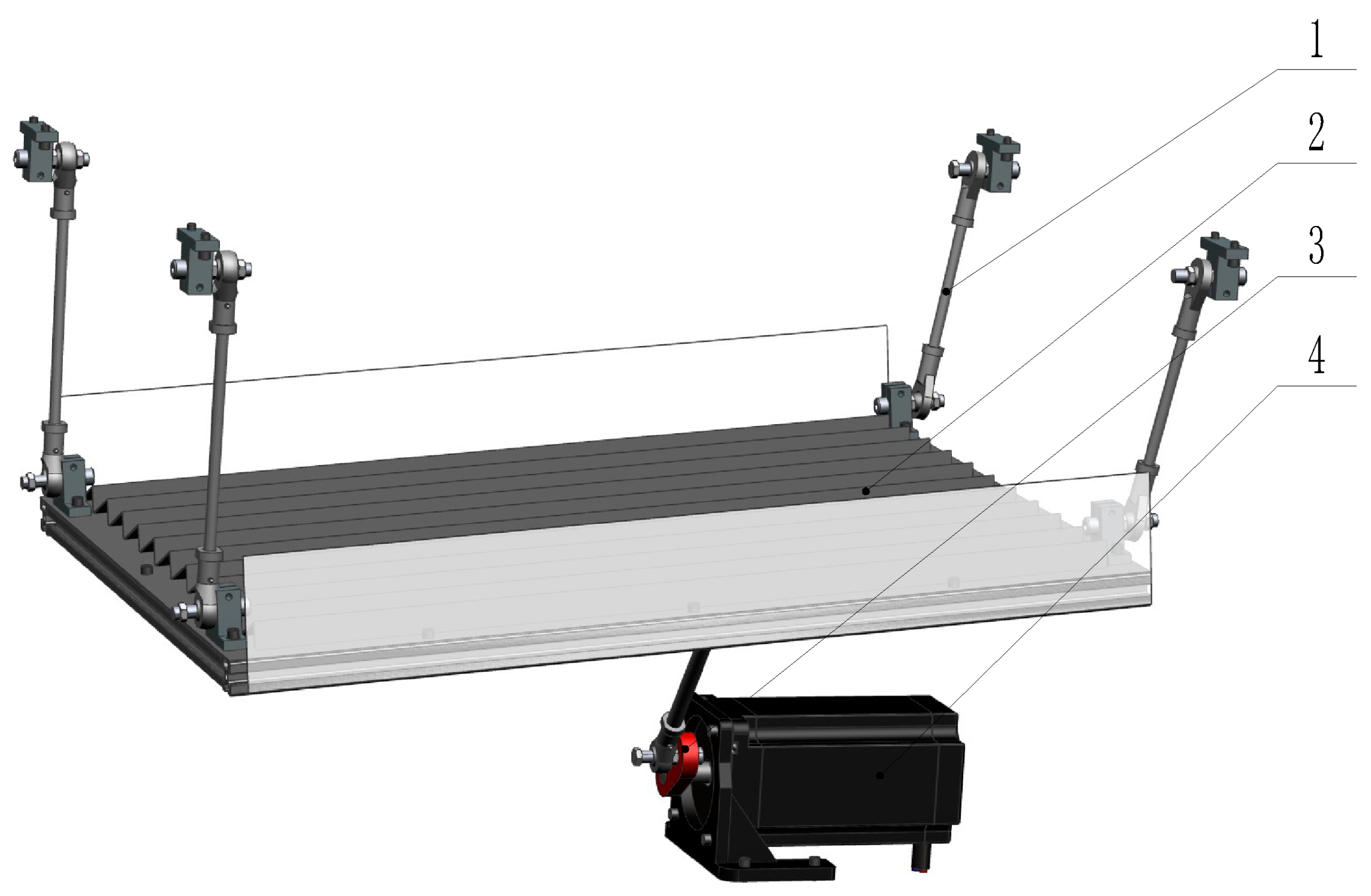
2. Structure and Working Principle of Longitudinal Axial Flow Stripper Reflux Homogenizing Device

In order to solve the problem of uneven distribution of discharged material screen surface load brought about by longitudinal flow threshing and the large entrainment damage caused by direct discharge of discharged material at the rear of the threshing drum, the team developed a discharged material screen surface load uniformity test bed based on longitudinal flow threshing, as shown in Figure 1, which mainly consists of stepped reflux plate, feeding device, blower, and clearing sieve, etc. The test bed was designed to be used as a test bed to test the performance of the threshing cylinder.
To ensure the consistency of all the discharges on the reflux plate, the reflux plate is connected to the frame with four equal-length, same-phase, and parallel booms; to realize the movement of the discharges on the reflux plate, the reflux plate is driven by crank linkage mechanism, which realizes the downward and lateral movement of the discharges in the vibration process of the reflux plate, the structure of the device is shown in Figure 2.
The working principle of the reflux homogeneous test bench is as follows: the reflux plate in front of the low back high in the crank linkage mechanism under the drive to do the left and right reciprocating movement, the realization of the dislodged material to do the longitudinal and transverse composite movement, that is, for the transverse, is located in the reflux plate side of the dislodged material with the reflux plate of the reciprocating movement, when the reflux plate to the left, dislodged material due to the inertia effect of the right side of the reflux plate movement; when the reflux plate to the right movement, the dislodged material Due to inertia, although there is a tendency to move to the left, but by the step structure of the reflux plate, can only be stagnant, so that after many cycles of reciprocating movement, to realize the left side of the dislodged material to the right, to achieve the effect of dislodged material in the screen surface of the sieve uniform distribution; for the longitudinal direction, due to the reflux plate before the front of the low after the high, so the dislodged material in the left and right at the same time, with the help of gravity along the reflux plate forward motion, to achieve The discharged material is returned from the end of the cleaning sieve to the middle and front part of the cleaning sieve, so as to achieve the purpose of even distribution of reflux and avoiding the discharged material at the back of the threshing drum to be discharged directly, which leads to the increase of the cleaning loss.

3. Determination of the Main Parameters of the Reflux Load Homogenizing Device

3.1. Determination of Reflux Plate Inclination Angle

The reflux plate is the core component to ensure that the discharged material is uniformly distributed on the screen surface of the cleaning sieve [23,24,25,26,27,28,29,30], not only to realize the uniform distribution of the discharged material along the width direction of the screen surface but also to realize the forward movement of the discharged material at the back of the threshing drum, to avoid the increase of cleaning loss caused by the discharged material at the back of the drum discharged directly, so the discharged material in the return plate is subjected to stress analysis as shown in Figure 3.
The smaller the inclination angle of the reflow plate, the smaller the downward movement speed of the discharged material on the reflow plate, although it can prolong the time of homogenization of the discharged material on the reflow plate and improve the uniformity of the transverse distribution of the discharged material on the screen surface, it may increase the risk of the accumulation of the discharged material on the reflow plate, or even clogging; on the contrary, if the inclination angle of the reflow plate is too large, the larger the speed of the discharged material in the downward movement of the reflow plate, and the reduced time of the discharged material’s rightward movement on the reflow plate, thus greatly affecting the uniformity of the lateral distribution of the discharged material on the screen surface. On the contrary, if the inclination angle of the return plate is too big, the speed of downward sliding movement of dislodged material on the return plate will be bigger, and the time of rightward movement of dislodged material on the return plate will also be reduced, which will have a great influence on the uniformity of transverse distribution of dislodged material on the sieve surface [31,32].
Assuming that the weight of the dislodged object is mg, the support force of the return plate on the dislodged object is N1, the angle of inclination of the return plate is β , and the friction force generated by the forward sliding of the dislodged object is F, we have:
The support force is:
N 1 = m g cos β
The friction force is:
F = tan φ m g cos β
Obviously, it is necessary to ensure that the dislodged material slides steadily along the surface of the reflux plate:
m g sin β F = tan φ m g cos β
The simplification yields:
β > φ
That is, the minimum inclination angle β of the return plate should be greater than the friction angle φ of the dislodged material with the return plate, i.e., according to the friction angle of the dislodged material with the return plate, the β take 26 ° ~ 33 ° .

3.2. Determination of Step Plate Spacing

In order to investigate the effect of the step plate spacing on the motion of the dislodged material, the force analysis of the dislodged material on the reflux plate; to simplify the analysis process, ignoring the effect of the angle of the step plate on the transverse movement of the dislodged material, take the dislodged material is in the plane of the reciprocating motion on the movement of the analysis of its motion, as shown in Figure 4.
Assuming the gravity force of the dislodged object mg, the support force of the reflux plate N2, and due to the inertia force F2 and the friction force fN2 of the dislodged object moving back and forth on the reflux plate, the equation of motion of the reflux plate is assumed to be x = A sin ω t , then the inertia force of the material moving with the return plate is:
F a = m g A ω 2 sin ω t
Friction is: F f = f N 2 = f m g .
Then the material is subjected to a combined force in the horizontal direction:
F = F f + F a = f m g m g A ω 2 sin ω t
The acceleration is:
a = F m g = f A ω 2 sin ω t
Obviously, the acceleration is not only changing in magnitude but also in direction, i.e., the dislodged material forms a reciprocating motion on the surface of the reflux plate.
Since the return plate is reciprocating under the action of the crank linkage mechanism, its equation of motion is x = A sin ω t , so the period of its reciprocal motion is:
T = 2 π ω
Due to the sinusoidal motion of the material on the surface of the reflux plate, the speed of the motion is x = A ω cos ω t , for the convenience of calculation, the point where the material velocity is 0 is selected as the starting motion position, x = A ω cos ω t = 0 .
Solve for t = 2 k π ± π 2 ω ( k = 1 , 2 , , n ).
So the motion displacement of the material in one vibration cycle is:
x = π 2 ω 3 π 2 ω v t d t = π 2 ω 3 π 2 ω ( a t + v 0 ) d t
In order to facilitate the calculation, combined with the dislodged object at the speed of 0 when the inertia force is the largest, so take the inflection point of the reciprocating motion of the dislodged object as the starting position, that is, v0 = 0.
Substitution of Equation (7) into Equation (9), we get:
x = π 2 ω 3 π 2 ω ( f A ω 2 sin ω t ) t d t = 1 2 f t 2 | π 2 ω 3 π 2 ω A ( ω T cos ω t sin ω t ) | π 2 ω 3 π 2 ω
That is, for each vibration, the displacement of the dislodged material on the return plate along the width of the screen is:
x = f π 2 ω 2 + f A
Consider that the dislodged material is moving back and forth across the reflux plate at t = [ π 2 ω , 3 π 2 ω ] , the dislodgement moves in a negative direction along the x-axis; Then t = [ 3 π 2 ω , 5 π 2 ω ] must be along the x-axis positively. Therefore, in order to realize the transverse movement of the dislodged material from left to right, the surface of the reflux plate is designed as the stepped plate structure shown in Figure 5, so as to ensure the smoothness of the movement of the material to the right and the blockage of the movement to the left, and to achieve the movement of the material to the right in the process of sliding down along the reflux plate, i.e., to improve the homogeneity of the dislodged material in the distribution on the surface of the reflux plate.
Let the angle between the hypotenuse of the stepped plate and the base plate be α , the spacing is W, the height is h, as shown in Figure 5.
Clearly, the theoretical spacing of the stepped plates is X = f π 2 ω 2 + f A .
In order to ensure the stability of the lateral movement of the dislodged material on the reflux plate, it was determined that the W = k X , Here k is the lateral movement coefficient, which is taken as k = 0.8–0.9, i.e., the displacement of the plate object to the right, X, is slightly greater than the width, W, of the stepped plate.
Further, assuming that the radius of the concave plate of the longitudinal flow threshing device is R, the number of steps n required for the material to move from the leftmost to the rightmost is:
n = int ( 2 R X ) + 1
That is, the step spacing is:
W = 2 R n = 2 R int ( 2 R X ) + 1 = 2 R int ( 2 R f π 2 ω 2 + f A )

3.3. Determination of Step Plate Height

As shown in Figure 5, in order to stagnate the leftward movement of the dislodged material with the reciprocating motion of the reflux plate, a stepped plate structure with a blocking effect is used. Obviously, the smaller the height of the ladder plate, the smoother the movement of the board to the right, but the poorer the ladder plate’s blocking effect; the greater the height of the ladder plate, although it can improve the ladder plate’s blocking effect on the board, but the smoothness of the board’s rightward movement of the board is worse.
Considering that harvesters are designed according to the feeding quantity, i.e., assuming that the feeding quantity of the harvester is q, and the wheat-to-grain ratio of the crop is k0, for longitudinal axial flow threshing harvesters, most of the grains are generally threshed in the first 1/3 of the threshing drum, i.e., only 1/3 of the grains in the rear 2/3 of the length of the drum are threshed, so assuming that the time for the grains to pass through the threshing drum is t, then the separation of the grain from the rear part of the threshing drum at time t The amount of dislodged material is:
Q z = 1 3 k 0 q t
Consider the longitudinal flow threshing device drum front 1/3 part, the lower part is equipped with a vibration deflector, so do not consider the drum front 1/3 of the dislodged material of the bias distribution problem, and the rear 2/3 part due to the direct fall in the clearing sieve and the total amount of Qz, if all of them are uniformly distributed in the reflux plate (the limit of the distribution of the amount of), according to the width of the return plate is equal to the diameter of the cylinder 2R, the length of the L, the dislodged material volumetric density is ρ , the thickness of the material layer δ is:
δ = Q z ρ 2 R L = k 0 q t 6 ρ R L
So the height h of the stepped plate is:
h = k 1 δ = k 0 k 1 q t 6 ρ R L
Here k1 is the obstruction coefficient of the ejected object. To ensure that the stepped plate effectively blocks the left movement of the object on the plate, k1 is taken as 1.1~1.3.

3.4. Determination of Reflux Plate Length

Considering that the longer the length of the return plate, the greater the distance of the dislodged material at the back of the drum can be returned forward, i.e., the longer that part of the dislodged material is separated on the screen surface, which is conducive to reducing the scavenging loss; however, excessive length not only leads to a complex structure, but also forms a pile-up of the dislodged material in the longitudinal direction of distribution, therefore, in order to determine the reasonable length of the return plate, the dislodged material distribution law test of longitudinal flow threshing was carried out, and a longitudinal flow threshing drum was The longitudinal flow threshing drum was set up below the receiving box as shown in Figure 6, and the receiving box was divided into 6 areas in the transverse and longitudinal directions, the longitudinal areas were numbered 1–6, i.e., counting the number of discharged material in columns 1–6 of the receiving box, and transverse areas were numbered a-f, i.e., counting the number of discharged material in rows 1–6 of the receiving box, and the curves of the test results were shown in Figure 6a,b.
From the experimental results, it is clear that the distribution of dislodged material in the longitudinal and transverse directions of the sieve surface for longitudinal axial flow threshing is indeed uneven. For the longitudinal direction, although the discharged material is concentrated in the first 1/3 of the sieve surface, which is consistent with the research result that the airflow action area is concentrated in the first 1/3 of the upper sieve surface, and although the content of the rear part becomes less, the direct discharge will increase the loss of clearing; and also consider that if the discharged material of 2/3 of the back of the threshing drum is directed to the first 1/3 of the upper sieve surface (which is approximated to be equal to the longitudinal direction of the drum 1/3), then it may result in the accumulation of discharged material in the middle of the back. Therefore, it is initially determined that the length of the return plate is the middle position of 2/3 of the length of the back of the drum, that is:
l = 1 / 3 L
Considering also the law of transverse distribution of dislodged material in the presence of longitudinal flow threshing, combined with the distribution of dislodged material over the length of the return plate, it is obvious that it is sufficient to realize that the distribution area of dislodged material on the left side can be moved to the right side where there is no dislodged material, as shown in Figure 7.
Assuming that G1 is the leftmost point of the back end of the reflux plate, G1G2G3G4 is the left side of the dislodged material accumulation area. Therefore, in order to ensure that the dislodged material on the reflux plate can be maximized in the shortest possible time to the right side of the uniform distribution, it is only necessary that the material at the point of G1 can be moved to the rightmost side of the reflux plate, i.e., the material walks through the longest trajectory G1G5, the trajectory and the left side of the boundary of the angle of G1G3 is θ , then:
tan θ = n W L
Based on the fact that the time for the dislodgement to move from the uppermost to the lowermost part of the return plate is equal to the time for the dislodgement to move from the leftmost to the rightmost part of the return plate, due to its sliding force:
F = m g sin β tan φ m g cos β
So the acceleration is:
a = F m = g sin β g tan φ cos β
Assuming that the initial velocity of the ejected object at that position is 0, the time tz for the ejected object to move from the top to the bottom is:
t z = 2 L a = 2 L g sin β g tan φ cos β
For the transverse direction, the transverse movement of the dislodged material is realized because the dislodged material can only rely on the reciprocating motion of the return plate. It is known from the previous section that the time taken for one reciprocation of the reflux plate is [ π 2 ω , 3 π 2 ω ] = π ω , there are n + 1 stepped plates on the reflux plate, so the time of lateral movement of the dislodged material is th, and:
t h = π ω ( n + 1 )
According to t z = t h :
2 L g sin β g tan φ cos β = ( n + 1 ) π ω
To wit:
L = ( n + 1 ) 2 π 2 2 ( g sin β g tan φ cos β )
Calculated by substituting the relevant parameters, L = 510~600 mm.

3.5. Determination of Return Plate Motor Speed

As before, in order to ensure that the dislodged material in the reflux plate maintains the same movement, the reflux plate is hooked up to four equal-length, same-phase, and parallel booms so that it makes a fixed-plane motion; furthermore, in order to simplify the small reflux plate in the vertical direction of the movement of the connecting rod is used in the connecting rod length is much longer than the length of the crank so that the reflux plate in the crank linkage mechanism driven by the crank linkage mechanism can be approximated to think of the reflux plate in the crank linkage mechanism under the action of the OM line for the direction of reciprocating motion, 2 r (r for the crank radius, shown in Figure 8) for the stroke of the linear reciprocating motion.
For the convenience of analysis, take the crank rotation center O as the coordinate origin, take the OM direction as the positive direction of the x-axis, take the perpendicular to the OM line upward as the y-axis direction, and take the negative direction of the crank and x-axis coincidence position as the crank starting position, then the motion of the dislodged object on the return plate is:
Displacement:
x = r cos ω t
Speed:
x = d x / d t = r sin ω t
Acceleration:
x = r ω 2 cos ω t
where r is the crank radius; ω is the crank slewing speed; and t is the time.
From the above acceleration equation, in t = [ 0 , π 2 ] [ 3 π 2 , 2 π ] time, the acceleration x″ is negative, the direction to the left; in t = [ 0 , π 2 ] [ 3 2 π , 2 π ] time, the acceleration x″ is positive, the direction to the right, the inertia force S and the direction of the acceleration is opposite.
In order to analyze the motion law of the dislodged object on the reflux plate, take the acceleration of the dislodged object as positive, i.e., when t = [ 0 , π 2 ] [ 3 2 π , 2 π ] , and analyze the force on the dislodged object at any position of the reflux plate, as shown in Figure 8, at this time the dislodged object is subjected to the force of gravity mg, the supporting force of the reflux plate N, the force of inertia S, and the friction between the dislodged object and the reflux plate F, where:
Inertial forces:
S = m r ω 2 cos ω t
Friction:
F = N tan φ
For calculation purposes, the effect of the inclination of the return plate on its positive pressure is not considered
F r o m { x = 0 y = 0 t o { S cos ( ε α ) + m g sin α = F N = S sin ( ε α ) + m g cos α
When the crank OA is located in quadrants I and IV, the acceleration x″ is positive and the direction is to the right, at this time the dislodged object is subjected to the force of gravity mg, the surface of the reflux plate on its support N, the inertia force is S = m r ω 2 cos ω t , friction is F = N tan φ , of which:
N = m g cos α + S sin ( α + ε )
Let the acceleration of the material extending the surface of CD be d 2 ξ C D d t 2 , then:
m d 2 ξ C D d t 2 = S cos ( α + ε ) m g sin α F
Simplified and obtained:
cos φ cos ( α + ε + φ ) d 2 ξ C D d t 2 = r ω 2 cos ω t g sin ( α + φ ) cos ( α + ε + φ )
Let cos φ cos ( α + ε + φ ) = σ , then the formula m d 2 ξ C D d t 2 = S cos ( α + ε ) m g sin α F can be written as:
1 σ d 2 ξ C D d t 2 = r ω 2 cos ω t g sin ( α + φ ) cos ( α + ε + φ )
When r ω 2 cos ω t > g sin ( α φ ) cos ( α + ε φ ) , since d 2 ξ C D d t 2 > 0 , the material slides to the left of the extended plate surface, when cos ω t = 1, the limiting angular velocity of the material sliding to the left can be obtained, namely:
ω 2 r g > sin ( α + φ ) cos ( α + ε + φ )
Let ω 2 r g = K , sin ( α + φ ) cos ( α + ε + φ ) = K 1 , K > K 1 is the condition for the material to slip to the left.
This in turn leads to the crank limit speed at which the material slips to the right, i.e.,:
n 1 = 30 π g sin ( α + φ ) cos ( α + ε + φ )
Similarly, it can be obtained that when the crank is in quadrants II and III, the index K 2 of the return plate motion for the material sliding to the right is:
K 2 = sin ( φ α ) cos ( α + ε φ )
That is, the material can slide to the right only when K > K 2 .
When N 0 , it means that the material is thrown up, and the condition that the material is thrown up can be found from N = m g cos α S sin ( α + ε ) :
ω 2 r g > cos α cos ( α + ε )
Let cos α cos ( α + ε ) = K 0 , then there is K > K 0 for the material to be thrown up.
Therefore, the movement state of the material on the reflux plate depends on the relationship between the movement index K of the reflux plate and K 1 and K 2 . The purpose of setting up the reflux plate is to equalize the material piled up on the left side of the plate surface to the right, and the surface of the reflux plate is equipped with a stepped plate to prevent the material moving to the right from moving to the left again, K > K 1 > K 2 is used.
Through the above analysis, it can be seen that when the rotational speed is 225~275 r/min, the material can cross the step plate in the reciprocating movement of the return plate to realize the movement of the material in the shaking plate, which can effectively solve the problem of accumulating the drum dislodged material.

4. EDEM-Based Simulation of Optimised Tests

Due to the unique structure of the stepped plate in the stepped reflux plate, which needs to be fixed by welding, the fabrication cycle is long and the production cost is high, resulting in the difficulty of the test in the bench; and the bench test is affected by the feeding device, which makes it difficult to simulate the distribution law of the dislodged material in the longitudinal flow. In order to speed up the research progress and shorten the test cycle, we choose to use EDEM simulation to explore the influence of the reflux plate on the distribution law of the dislodged material, in order to verify the previous design.

4.1. Model and Material Properties

It is known that the components of the exudate are mainly kernels, cob and bracts, in the simulation analysis to simplify the processing, and only the kernels and cob simulation analysis, the establishment of the corresponding particles model, the BulkMaterial module is applied in the modelling, the results of the resulting model are shown in Figure 9 and Figure 10 below, the maize kernel is 12 mm long, 8 mm wide, 5 mm thick, the length of the cob is 50 mm, and the radius is 10 mm. The contact parameters between the corn kernel and the stepped plate are shown in Table 1 below and the mechanical properties of different materials are shown in Table 2.
Unless otherwise stated, the parameters related to model and material properties set during simulation are consistent with Table 1 and Table 2.

4.2. Reflux Plate Simulation Model

In the study in order to analyse the changes in the distribution of dislodged material after the change of the angle α of the step plate in the reflux plate, the simulation study was carried out for the reflux homogeneous device, and the model established is shown in Figure 11, and the inclination angle α of the step plate set in the single-factor analysis was 26°, 28°, 30°, 32°, and was marked by the ordinal number as 1, 2, 3, and 4 for the sake of convenience in describing.
Through the UG12.0 software modeling, this device is simplified to form the length and width of 600 mm × 540 mm of the return plate plate, above the return plate, set up 6 columns of 480 mm long, 80 mm wide particle plant, particle plant from the return plate 100 mm, 6 columns of particle plant corresponds to the longitudinal axis of the flow of the roller transverse 1–6 columns of field test data; in the corresponding position of the clearing sieve set up long 600 mm long and 600 mm wide receiving box is set at the position corresponding to the clearing screen, and the distance from the return plate is 180 mm. The simplified homogeneous device model is converted into STL format and imported into EDEM 2020 software, and the simulation model of the return plate is shown in Figure 12.
Set the motion of the reflux plate as “Sinusoidal Translation”, the frequency is 4.2 Hz, the vertical amplitude is 13 mm, the target time step is 0.01 s, the vibration start time is 1 s, the total time is 10 s, the total mass of the material is 2000 g, the flow rate is 200 g/s. The total mass of the seeds was 2000 g and the flow rate was 200 g/s.
The seed mass as well as the generation rate of the seed pellet plant is shown in Table 3.
The tramp mass and generation rate of the tramp particle plant are shown in Table 4.

4.3. Effect of Stepped Plate Angle on the Distribution of Exudates

The transverse region was divided in the EDEM 2020 software, as shown in Figure 13 below, and the region was averaged into six zones in the transverse direction during the simulation analysis, and the coordinates of the measured region in the X-direction were [500, 150], in the Y-direction were [1100, 700], and in the Z-direction were [300, 610], all in mm.
In order to compare the effects of the programmes, statistical analysis was performed to determine the mass of the exudate within the six zones in the lateral direction, denoted as Ai, corresponding to the following expression:
B i = A i A × 100 %
A is the quantity of all the exudates in the six regions, Bi is the ratio of the quantity of exudates in each region, and the relevant data were input into origin for visualisation to plot the Bi curve as shown below.
Specifically analysing the data in Figure 14, it can be found that when the angle of the stepper plate is 28°, the lateral uniformity effect is better than that of 26°; when this parameter is in the interval of 30° and 32°, the uniformity of transverse dislodgement is close to the situation; in addition, according to the analysis of the previous section, it can be seen that the angle of 32° will have a negative impact on the conveying efficiency and the corresponding uniformity effect is basically similar to the angle of the stepper plate of 30°, so 28° is relatively suitable for the stepped plate angle. Therefore, 28° is a relatively suitable angle for the ladder plate.

4.4. Optimisation of Stepped Plate Angle Parameters

In the study, in order to compare the homogeneity effect of each programme, the standard deviation of the ratio of the number of dislodged material in each area of the transverse direction was set as an evaluation index, and the smaller the standard deviation, the better the homogeneity was considered. The expression for the standard deviation of discharged material is:
σ = s q r t [ i = 1 6 ( B i B ¯ ) 2 / 6 ]
In the formula
σ —Standard deviation of the percentage of the number of dislodged material in the transverse region;
B i —Percentage of number of horizontal regions;
B ¯ —Mean number of volume shares;
The simulation results were exported to the simulation data, and the distribution of the exudates is shown in Figure 15.
The standard deviation of the rejects for each scenario is shown in Figure 16.
The standard deviation of the distribution of the dislodged material in the design scheme is calculated, and the optimal scheme is the standard deviation of 1.62 for a stepped plate at 28°, i.e., the best homogeneous distribution of the dislodged material is achieved when the angle of the stepped plate is 28°, which is an improvement of 40% in comparison with the other schemes.

5. Bench Test

5.1. Test Conditions

The test was carried out in the team’s self-developed longitudinal flow threshing based screen load homogenisation test bed for discharged material, as shown in Figure 17. The main testing equipment used to test the homogenisation effect of maize kernels included: receiving box (100 mm × 100 mm × 100 mm), electronic stopwatch of type J9-2, electronic crane scale of type HCS-50 and electronic balance of type JJ3000.
Its main technical parameters are shown in Table 5 below.
The mass ratio of the test material composition is shown in Figure 18.

5.2. Test Factors and Indicators

The previous theoretical analysis shows that the tilt angle, vibration amplitude, and motor speed of the stepped reflux plate in the process of reflux homogenization are the key factors determining the effect of homogenized reflux, so through theoretical analysis, the tilt angle of the stepped reflux plate, vibration amplitude, and motor speed are selected as the test factors. The levels of orthogonal test factors are as follows: 26°~32° reflux plate inclination angle, 15 mm~21 mm vibration amplitude, and 225 r/min~275 r/min motor speed.
Due to the increase of the stepped return plate, in the longitudinal direction of the drum, located in the back section of the drum of the dislodged material cleaning time is relatively longer, in the radial direction of the drum, due to the stepped return plate extended drum radial reciprocating movement, so that the return flow of the dislodged material is relatively uniformly back to the screen surface of the cleaning sieve so that the cleaning sieve screen surface pressure is relatively reduced to increase the efficiency of the cleaning. Therefore, the seed impurity rate was selected as the test index, a certain quality of sample seeds was taken out from the receiving box, from which the impurities (spindle, bracts, and leaves, etc.) were selected, and the total mass of sample seeds and the mass of impurities were weighed respectively, and the seed impurity rate was calculated by the formula:
Z = m z m h × 100 %
In the formula
Z —seed impurity rate, expressed as a percentage, %;
m z —mass of impurities, measured in grams, g.
m h —mixed seed mass, measured in grams, g.

5.3. Test Methods

Before each group of tests, the use of electronic scales will be weighed out of the material in proportion to the reflux device feed box, the use of the device to simulate the back section of the drum out of the material falling, out of the material first fell to the reflux plate, after the reflux plate after the uniform distribution of the out of the material fell to the surface of the sieve for cleaning, after the cleaning scattered to the arrangement of the sieve below the receiving box.
The Box-Behnken response surface method [33,34,35] was applied in this experimental study while referring to the results obtained in the previous article, three factors were selected as the independent variables, including the tilt angle of the return plate, the motor speed and the vibration amplitude of the return plate, and the dependent variable was the impurity rate of the grain, and then a three-factor, three-level orthogonal test was carried out by the research objectives, and the factors were coded for ease of processing, and the obtained results were as shown in Table 6, with all the factors coded at three levels of −1 (low), 0 (medium) and 1 (high). All the test factors were coded as −1 (low), 0 (medium), and 1 (high) levels, and the coded values indicated the level of each factor, and the factors were adjusted in the process of the test, and the mean value was taken in three repetitions, and the evaluation index was set as the standard deviation of the quality ratio of the extracted material.

5.4. Analysis of Test Results

The design of the experimental program and data analysis in this subsection were completed with the help of tools provided by Design-Expert 8.0 software. In this experiment, the main focus was on the seed impurity rate as the test assessment index. A total of 17 tests were carried out, of which 12 groups were analyzing factorization points and the rest were zero points. In order to minimize the deviation of the test results from the actual values, the zero-point test was repeated several times. The finalized test program and results are shown in Table 7 (X1, X2, and X3 are the coded values of return plate tilt angle, motor speed and return plate vibration amplitude, respectively).
The data related to the tests were entered into Design-Expert for processing, and the results of the calculations are summarized in Table 8 below.
These data were analysed by quadratic multiple regression to obtain the final quadratic multiple correlation equation with the following expression:
Y = 1.57 0.51 X 1 + 0.22 X 2 0.19 X 3 + 0.085 X 1 X 2 0.29 X 1 X 3 + 0.58 X 2 X 3 + 0.73 X 1 2 + 0.93 X 2 2 + 0.74 X 3 2
where X 1 is the tilt angle; X 2 is the motor speed; and X 3 is the amplitude.
Based on the results obtained above, it can be found that factors X 1 , X 2 , and X 3 significantly affect the rate of seed impurity content, and the level of significance of these three factors is ranked, and the descending order results are vibration frequency X 2 , tilt angle X 1 , and amplitude X 3 .
Further, the effect of the interaction of these factors on this indicator is analyzed through the response surface method, in which one of the factors is set fixed and then the effect of the remaining two factors is analyzed.
1. When the tilt angle of the return plate was 29°, the effects of motor speed and vibration amplitude on the seed impurity rate were obtained, as shown in Figure 19. With the increment of motor speed, the seed impurity rate showed a trend of decreasing and then increasing. This is because the motor speed has a significant effect on the uniformity of reflux reject distribution. In the case of low motor speed, the acceleration of the material is small, resulting in increased difficulty of the material to cross the stepped plate, which causes the material to pile up on one side, resulting in poor uniformity of the rejects of the reflux plate, which leads to an increase in the load on the sieve surface of the cleaning sieve, and the excessive sieve surface load leads to the difficulty of cleaning the rejects of the reflux plate, which results in a high rate of impurity content. As the motor speed increases, the acceleration of the material increases, the movement speed of the material on the surface of the reflux plate increases, and the uniformity of the reflux discharged material becomes better, which leads to a smaller load on the screen surface of the cleaning sieve, and the efficiency of the cleaning is improved, and the impurity rate of the grains is reduced. However, as the motor speed is further increased, too high a speed will cause the material to cross two or even three-step plates at a time, so that the movement stroke of the material in the reflux plate is too long, resulting in a concentrated accumulation of the material on one side of the reflux plate, or even causing a blockage, resulting in a further increase in the impurity rate of the seeds.
With the increase of the amplitude of the reflux plate, the impurity rate of the seeds appeared obvious changes, specifically manifested as the first decline and then increase. The reason for this phenomenon is that the larger the amplitude, the higher the efficiency of the material crossing the stepped plate, so that the material piled up on one side can quickly move to the other side, greatly reducing the thickness of the material piled up on the left side, thus improving the uniformity of the discharged material. However, too high an amplitude will lead to an increase in the amplitude of the movement of the material, resulting in a poor homogenization effect of the refluxed discharged material, increasing the screen surface load, reducing the cleaning efficiency, and leading to an increase in the impurity rate. In serious cases, the material may even be vibrated out of the reflux plate, resulting in seed loss.
2. When the speed of the return plate motor is 250 r/min, the effects of the tilt angle of the reflux plate and the vibration amplitude on the homogenization effect of the refluxed rejects were obtained, as shown in Figure 20. With the increase of the inclination angle of the reflux plate, the impurity rate of the seeds showed a trend of decreasing first and then increasing. This is because the inclination angle of the reflux plate has a significant effect on the homogeneity of material distribution. When the inclination angle increases, the smoothness of the reflux dislodged material sliding down from the reflux plate increases, thus reducing the residence time of the material on the reflux plate, making the homogeneous distribution time of the material on the reflux plate shorter, and avoiding the accumulation of the material. However, when the inclination angle of the reflux plate continues to increase, the movement distance of the material on the reflux plate is further shortened, resulting in the material sliding down from the reflux plate without being sufficiently homogenized, thereby causing the homogenization time of the refluxed dislodged material to be reduced, the homogeneity of the refluxed dislodged material to deteriorate, and the load on the screen surface to be increased, resulting in the increase in the rate of impurity content of the seed grains.
The size of the reflux plate amplitude does have a significant effect on the homogeneity of the material, and within a certain range, as the amplitude of the reflux plate increases, the efficiency of the material crossing the stepped plate increases, which enables the material piled up on one side to move quickly to the other side, and this rapid movement greatly reduces the thickness of the material piled up on the left side, thereby improving the homogeneity of the refluxed dislodgement material. However, when the amplitude is too large, the material may accumulate on the other side of the reflux plate and the reflux rejects are not evenly distributed. In this case, the clearing effect of the reflux rejects is not good, and with too large an amplitude, the seeds may even be vibrated out of the reflux plate, increasing the impurity content of the seeds.
3. When the vibration amplitude of the reflux plate is 18 mm, the influence of the tilt angle of the reflux plate and the vibration frequency on the impurity rate of the seeds is obtained, as shown in Figure 21. With the increase of the inclination angle of the reflux plate, the impurity rate of the seeds decreased and then increased. This is because the tilt angle of the reflux plate has a significant effect on the uniformity of material distribution. When the inclination angle increases, the smoothness of the seeds sliding down from the reflux plate increases, which reduces the residence time of the material on the reflux plate, making the movement distance of the material on the reflux plate shorter, and avoiding the accumulation of the material. However, when the inclination angle of the reflux plate continues to increase, the movement distance of the material on the reflux plate is further shortened, resulting in the reflux dislodged material sliding down from the reflux plate without being sufficiently homogenized, thereby reducing the homogeneity of the refluxed dislodged material, and the load on the screen surface increases, resulting in the impurity rate of the seed grains increasing again.
With the increase in motor speed, the seed impurity rate showed a tendency to decrease and then increase. This is because the motor speed has a significant effect on the uniformity of the distribution of the stripped material. When the motor speed is low, the acceleration of the material is small, resulting in increased difficulty for the material to cross the step plate, which causes the material to pile up on one side. This will cause the uniformity of the dislodged material from the return plate to deteriorate, forming a distribution law of high on the left side and low on the right side, which will increase the load on the screen surface of the left side of the cleaning sieve, and reduce the cleaning efficiency. On the contrary, too high rotational speed will make the material cross two or even three stepped plates at a time, resulting in the accumulation of material on the reflux plate, and serious cases, it may even lead to a clogging phenomenon. In this case, the distribution pattern of the reflux dislodged material will show the pattern of high on the left side, low in the middle, and high on the right side, which will also increase the load of the cleaning screen and lead to an increase in the impurity rate of the seeds.

5.5. Optimization of Parameters

After the above study, in order to determine the optimal combination of factors and parameters, the regression equations were analyzed to obtain a nonlinear planning model as shown below.
{ min Y ( X 1 , X 2 , X 3 ) s . t { 26 ° X 1 32 ° 225   r / min X 2 275   r / min 15   mm X 3 21   mm
According to the obtained rounding optimization results, it was concluded that when the tilt angle of the return plate was 28.7°, the motor speed was 247 r/min, and the vibration amplitude was 18.3 mm, the homogenization effect was optimal, and the rate of seed impurity content was 0.48%.
In order to verify whether the optimization analysis results are correct or not, the impurity rate was examined under the optimal parameter combination and repeated six times under the same conditions to reduce the interference of error factors, and the results obtained were sorted out as shown in Table 9, according to which it can be found that the impurity rate of the seeds was 0.48%, and the results of the round-robin optimization were credible.

6. Field Trial Validation

In order to further verify the adaptability of the design of the reflux homogenizing device and to determine the optimal parameter combination of the designed stepped reflux plate in the field operation process, the field test of the reflux homogenizing device was carried out based on the completion of the theoretical design of the reflux homogenizing device, the trial production of the test bed and the bench test.
The terrain of the test site is flat, the crop growth is uniform, no falling phenomenon, the planting row spacing of corn plants is 560~600 mm, with an average value of 590 mm, and the average plant height is 2097.5 mm, the corn cob is full, with no obvious sagging, the water content of corn kernels is 25.8~26.5%, and the soil is dominated by subclass tidal soil, and the test specimen is shown in Figure 22.
According to GBT21962-2020 [36] corn harvester test method, the test corn field area is taken as 20 m × 20 m, and the forward speed of the harvester is kept at 0.48 m/s during the test. With other factors remaining unchanged, the parameters of the reflux homogenizing device are adjusted, and the pre-optimization data are divided into two groups with the optimized data, the original scheme (reflux plate tilt angle of 29°, motor speed of 250 r/min, reflux plate amplitude 18 mm), optimization scheme (reflux plate tilt angle 28.3°, motor speed 247 r/min, reflux plate amplitude 18.3 mm), the two schemes were repeated three times to verify the test, and after the end of the test, a certain amount of maize kernels were taken out of the granary in the test bag, and the kernels and impurities (bracts, stalks, broken cores) were selected from the sample, weighed with electronic scales, and weighed separately. The kernels, and impurities (bracts, stalks, broken cores) in the samples were selected and weighed with electronic scales to calculate the impurity content rate, and the test results are shown in Table 10.
Through the field test verification, the test results are basically consistent with the pre-test results, and the error between the optimization test results and the test verification results is less than 5%, indicating that the optimal parameter combinations obtained from the optimization model are more accurate.

7. Conclusions

  • Aiming at the problems of uneven distribution of dislodged material on the screen surface of longitudinal flow grain combine harvester, a large difference in material clearing time, and large clearing loss, a dislodged material homogenizing device that can realize reflux and homogenization of dislodged material at the rear of longitudinal flow has been developed. The structure and motion parameters of the reflux plate were determined, and simulation tests were carried out to verify the optimal parameters of the angle of the stepped plate.
  • The relevant test bench was set up, and the Box-Behnken test method was adopted to determine the influence law of each factor on the operating effect and the optimal parameter combination, and the results showed that the tilting angle of the reflux plate, the motor speed and the amplitude had a significant influence on the distribution uniformity of the material on the screen surface; the optimal parameter combination was determined to be the angle of the reflux plate configuration at 28.7°, the motor speed at 247 r/min, and the seed inclusion rate of 0.48% at an amplitude of 18.3 mm. The optimum combination of parameters was determined to be 28.7°, 247 r/min, 18.3 mm, and 0.48% of impurity rate.
  • Under this condition, field tests were carried out to verify the results, which were basically consistent with the results of the previous tests, and the error between the optimized test results and the verification results was less than 5%, which proved that it could effectively improve the performance of scavenging and reduce the rate of impurity content.

Author Contributions

Methodology, J.M. (Jiarui Ming); Software, J.Y. and Y.C.; Data curation, D.Y., J.M. (Jie Ma) and Y.W.; Writing—original draft, J.M. (Jiarui Ming); Writing—review & editing, D.G.; Visualization, Q.H.; Supervision, D.G. All authors have read and agreed to the published version of the manuscript.

Funding

This research was supported by the Natural Science Foundation of Shandong Province 623 (ZR2022ME064). This research was supported by the national key research and development plan 624 (2021YFD20000502).

Institutional Review Board Statement

Not applicable.

Data Availability Statement

Data is contained within the article.

Conflicts of Interest

The authors declare no conflicts of interest.

References

  1. Li, X.P.; Zhang, W.T.; Xu, S.D. Low-Damage Corn Threshing Technology and Corn Threshing Devices: A Review of Recent Developments. Agriculture 2023, 13, 1006. [Google Scholar] [CrossRef]
  2. Fu, J.W.; Xie, G.; Ji, C. Study on the Distribution Pattern of Threshed Mixture by Drum-Shape Bar-Tooth Longitudinal Axial Flow Threshing and Separating Device. Agriculture 2021, 11, 756. [Google Scholar] [CrossRef]
  3. Yue, D.; Wang, Q.H.; He, Q.H. A Study of the Distribution of the Threshed Mixture by a Double Longitudinal Axial Flow Corn Threshing Device. Agriculture 2024, 14, 166. [Google Scholar] [CrossRef]
  4. Hao, J.F.; Han, Z.D.; Liu, G.M. Research Status and Development Trend of Cleaning Device of Corn Thresher. J. Anhui Agric. 2016, 44, 322–324+330. [Google Scholar] [CrossRef]
  5. Hao, F.P.; Chen, Z. Actuality of Domestic and Foreign Corn Harvester. Agric. Mech. Res. 2007, 10, 206–208. [Google Scholar]
  6. Cui, T.; Fan, C.L.; Zhang, D.X. Research Progress of Maize Mechanized Harvesting Technology. J. Agric. Mach. 2019, 50, 1–13. [Google Scholar]
  7. Chen, Z.; Hao, F.P.; Wang, F.D. Development of Technology and Equipment of Corn Harvester in China. J. Agric. Mach. 2012, 43, 44–50. [Google Scholar]
  8. Wang, W.Z.; Liu, W.W.; Yuan, L.H. Calibration of discrete element parameters of wheat plantsat harvest period based on EDEM. J. Henan Agric. Univ. 2021, 55, 64–72. [Google Scholar] [CrossRef]
  9. Zhou, Y. Design and Test of Automatic Equidistribution Device for Tangential and Longitudinal Flow Grain-MOG Mixture. Bachelor’s Thesis, Jiangsu University, Jiangsu, China, 2019. [Google Scholar]
  10. Zhang, M.; Jin, C.; Liang, S.; Tang, Q.; Wu, C. Parameter optimization and experiment on air-screen cleaning device of rapeseed combine harvester. Trans. Chin. Soc. Agric. Eng. 2015, 31, 8–15. [Google Scholar]
  11. Li, M.M. Unusual Unseen Harvesting Shows Its Promise—Krasse LEXION 770 Combine Harvester Helps 2012 Autumn Harvest in 852 Farms. Agric. Mach. 2012, 86–89. [Google Scholar] [CrossRef]
  12. CaseIH. Case AF4000 Series Axial Drum Combine Harvester, Multi-Purpose. Agric. Mach. 2020, 20. [Google Scholar] [CrossRef]
  13. Claas. All-round Harvesting King—CLAAS LEXION 700 Series Combine Harvester. Agric. Mach. 2015, 51. [Google Scholar]
  14. Wang, Y.H. High-performance Kubota PRO488 combine harvester. Agric. Mach. 2002, 42. [Google Scholar]
  15. Li, B.H.; Yi, S.J.; Jiang, N. Axial flow threshing and separating device discharged material along the drum tangential distribution law. Mod. Agric. 2005, 10, 31–32. [Google Scholar]
  16. Guo, Y.; Li, Y.M.; Li, H.C. The Radial Distribution Regularities of Emerging Object with Longitudinal Axial Flow Threshing and Separating Device. Res. Agric. Mech. 2011, 33, 110–112. [Google Scholar] [CrossRef]
  17. Geng, D.Y.; He, K.; Wang, Q. Design and Experiment on Transverse Axial Flow Flexible Threshing Device for Corn. J. Agric. Mach. 2019, 50, 101–108. [Google Scholar]
  18. Fu, W.; Yang, L.D.; He, R. Analysis and Improvement of Oscillating Plate of Grain Combine Harvester Journal of Shihezi University. Natureal Sci. 2012, 30, 249–251. [Google Scholar] [CrossRef]
  19. Fan, C.L.; Cui, T.; Zhang, D.X. Design and Experiment of Double-layered Reverse Cleaning Device for Axial Flow Combine Harvester. J. Agric. Mach. 2018, 49, 239–248. [Google Scholar]
  20. Cheng, C.; Fu, J.; Chen, Z. Optimization Experiment on Cleaning Device Parameters of Corn Kernel Harvester. J. Agric. Mach. 2019, 50, 151–158. [Google Scholar]
  21. Ma, Z.; Li, Y.M.; Xu, L.Z. Discrete-element method simulation of agricultural particles’ motion in variable-amplitude screen box. Comput. Electron. Agric. 2015, 118, 92–99. [Google Scholar] [CrossRef]
  22. Wang, D.J.; Choe, J.S. Development Status and Trend of Large Feed Grain Axial Threshing Equipmen. Agric. Technol. Equip. 2017, 330, 81–84. [Google Scholar]
  23. Zhao, H.S.; Bao, Y.X.; Chen, S.Y.; Yang, X.X. Current situation and development tendency of high-frequency vibration screen technology and equipments at home and abroad. Min. Mach. 2011, 39, 83–88. [Google Scholar] [CrossRef]
  24. Zhang, Y.F.; Lai, Y.J.; Zhang, K.; Sun, J.J. Research on The Axial Direction Distribution Regularities of Emerging Object with Axial Flow Threshing Installation. J. Heilongjiang Bayi Agric. Reclam. Univ. 2006, 18, 34–36. [Google Scholar]
  25. Zhang, J. Numerical Simulation and Experiment of Cranklink Organization Vibration Screener Based on Discrete Element Method. Bachelor’s Thesis, Northwest A & F University, Yangling, China, 2018. [Google Scholar]
  26. Xia, X.H.; Jin, W.M.; Zhang, Z.L. Simulation research, application status and development trend ofvibrating screen. J. Cent. South Univ. Sci. Technol. 2020, 51, 2689–2706. [Google Scholar]
  27. Wang, Z.H.; Wang, G.Y.; Liu, W.W. Present status and developing tendency of vibration screen. J. Shenyang Arch. Civ. Eng. Inst. 1999, 15, 78–82. [Google Scholar]
  28. Wang, L.J.; Li, R.; Yu, Y.T. Design and Test of Double-layer Non-parallel Vibrating Screens. J. Agric. Mach. 2019, 50, 130–139. [Google Scholar]
  29. Wang, L.J.; Duan, L.K.; Zheng, Z.H. Optimization and Experiment on Driving Mechanism of Vibrating Screen with Three Translations and Two Rotations. J. Agric. Mach. 2018, 49, 138–145. [Google Scholar]
  30. Xu, J.; Xiong, L.B.; Chen, P.L. The Design of a New Type Grain Lateral Vibration Plane Screen. Res. Agric. Mech. 2006, 110–111+114. [Google Scholar]
  31. Shen, D.C.; Hao, X.L.; Hu, D.S. The Considerable Problem When Design Oscillating Grain Pan. J. Jiamusi Inst. Technol. 1993, 11, 213–216. [Google Scholar]
  32. Yi, S.J.; Tao, G.X.; Mao, X. Comparative experiment on the distribution regularities of threshed mixtures for two types of axial flow threshing and separating installation. Trans. CSAE 2008, 24, 154–156. [Google Scholar]
  33. Geng, D.Y.; Zhang, D.L.; Wang, X.Y. New Agricultural Mechanics; Defense Industry Press: Beijing, China, 2011. [Google Scholar]
  34. Xu, X.H.; He, M.Z. Experimental Design with Design-Expert, SPSS Applications; Science Press: Beijing, China, 2010. [Google Scholar]
  35. Wang, Y.F.; Wang, C.G. The Application of Response Surface Methodology. J. CUN Nat. Sci. Ed. 2005, 14, 5. [Google Scholar]
  36. GB/T 21962-2020; Corn Combine Harvester. State Administration for Market Supervision and Administration, China National Standardization Administration: Beijing, China, 2020.
Figure 1. Schematic diagram of the structure of the test bench for uniformly distributed reflux of extracted materials based on longitudinal flow threshing. (1). Feed box. (2). Return plate. (3). Electronic control system. (4). Cleaning sieve. (5). Receiving box.
Agriculture 14 00731 g001
Figure 2. Structure diagram of stepped reflux plate cleaning device. (1). Boom. (2). Stepped return plate. (3). Crank rocker mechanism. (4). Motor.
Agriculture 14 00731 g002
Figure 3. Schematic diagram of reflux board configuration angle. mg—Weight of ejected material. N1—The support force of the reflux plate on the ejected material. F—The frictional force generated by the forward sliding of the ejected object. β —Reflux plate inclination angle.
Agriculture 14 00731 g003
Figure 4. Stress Analysis Diagram of Screen Material. N2—the support force of the reflux plate. F2—the inertia force. fN2—the friction force.
Agriculture 14 00731 g004
Figure 5. Ladder plate structure.
Agriculture 14 00731 g005
Figure 6. Schematic diagram of axial and longitudinal distribution of drum dislodged material.
Agriculture 14 00731 g006
Figure 7. Analysis of the trajectory of the material on the reflux plate.
Agriculture 14 00731 g007
Figure 8. Reflow plate motion analysis.
Agriculture 14 00731 g008
Figure 9. Corn Grain Model.
Agriculture 14 00731 g009
Figure 10. Corn cob model.
Agriculture 14 00731 g010
Figure 11. Schematic diagram of the inclination angle of the stepped board.
Agriculture 14 00731 g011
Figure 12. Ladder board simulation model. (1). Pellet plant. (2). Step plate. (3). Calculation area. (4). Catch box. (5). Simulated particles.
Agriculture 14 00731 g012
Figure 13. Horizontal area division setting.
Agriculture 14 00731 g013
Figure 14. Mass ratio of lateral protrusion distribution.
Agriculture 14 00731 g014
Figure 15. Horizontal statistics of ejected materials.
Agriculture 14 00731 g015
Figure 16. Comparative standard deviation test for exudates.
Agriculture 14 00731 g016
Figure 17. Test rig for screen load homogenization of discharged material for threshing in longitudinal axial flow. (1). Feed box. (2). Return plate. (3). Electronic control system. (4). Cleaning sieve. (5). Receiving box.
Agriculture 14 00731 g017
Figure 18. Mass ratio of each component in the extracted material.
Agriculture 14 00731 g018
Figure 19. Analysis of the effects of the interaction of motor speed and vibration amplitude.
Agriculture 14 00731 g019
Figure 20. Analysis of the effect of the interaction between the tilt angle and vibration amplitude of thereflux plate.
Agriculture 14 00731 g020
Figure 21. Analysis of the effect of the interaction between the tilt angle of the reflux plate and the motor speed.
Agriculture 14 00731 g021
Figure 22. Field experiment.
Agriculture 14 00731 g022
Table 1. Contact Parameters of Different Materials.
Contact ParameterCoefficient of RestitutionCoefficient of Static FrictionCoefficient of Rolling Friction
Corn kernels/
corn kernels
0.30.50.01
Corn kernels/
step plates
0.30.380.01
Corn kernels/
step plates
0.290.380.01
Maize kernel/
cob
0.20.60.01
Corn kernels/
corn kernels
0.30.70.01
Table 2. Mechanical Properties of Different Materials.
MaterialsSorghumStep Plates
Poisson’s ratio0.30.24
Shear modulus/Pa1.0 × 1077.9 × 107
Densities/kg·m−39007850
Table 3. Grain Particle Factory.
Column 1Column 2Column 3Column 4Column 5Column 6
Seed quality (g)506.8352.4204167.2183.2203.2
Rate of seed production (g/s)101.3670.4840.2433.4436.6440.64
Table 4. Miscellaneous Particle Factory.
Column 1Column 2Column 3Column 4Column 5Column 6
Trash mass (g)54.865.655.652.821.635.2
Rate of generation of impurities (g/s)10.6613.1213.0410.564.326.74
Table 5. Main technical parameters of corn cleaning and uniform distribution test bench.
Sports EventWork Unit
(One’s Workplace)
Parameters
L × W × Hmm1540 × 640 × 1000
Motor power of cleaning sieveKW2.2
Motor power of reflux plateKW3
Cleaning sieve sizemm540 × 1200
Reflux plate sizemm480 × 560
Fan speedr/min900~1500
Dimensions of collection unit (L × W)mm600 × 400
Table 6. Factors and coding of experiment.
EncodingsFactors
Tilt   Angle   X 1 Motor   Speed   X 2 /r/min Amplification   X 3 /mm
−12622515
02925018
13227521
Table 7. Test design scheme and results.
Serial NumberTilt Angle X1Motor Speed X2Amplification X3Seed Impurity Rate Y/%
1−1−102.41
21−103.27
3−1103.01
41104.21
5−10−12.63
610−13.05
7−1012.44
81014.03
90−1−13.58
1001−12.54
110−112.78
120114.07
130001.56
140001.55
150001.57
160001.58
170001.62
Table 8. Analysis of variance results of grain impurity content.
Source of VariationThe Sum of the Squared Deviations from the Mean(Number of) Degrees of FreedomMean SquareFp
model13.6391.5149.3<0.0001 **
X 1 2.0712.0767.4<0.0001 **
X 2 0.410.413.040.0086 **
X 3 0.2910.299.40.0182 *
X 1 X 2 3 × 10−213 × 10−20.940.3644
X 1 X 3 0.3410.3411.140.0125 *
X 2 X 3 1 × 10−311.3644.180.0003 **
X 1 2 2.2212.2272.24<0.0001 **
X 2 2 3.6513.6518.79<0.0001 **
X 3 2 2.3312.3375.76<0.0001 **
residual0.2273 × 10−2
lost proposal0.2130.0744.330.0016
pure error6 × 10−341.5 × 10⁻³
inaccuracies13.8516
Note: ** means that the test factor is significant at the 0.01 level of significance; * means that the test factor is significant at the 0.05 level of significance.
Table 9. Validation test results.
Serial NumberSeed Impurity (%)
10.48
20.51
30.49
40.52
50.47
60.48
Table 10. Field test results.
Test NumberOriginal Program Impurity Rate
(%)
Optimization Plan Impurity Rate (%)
11.580.48
21.570.45
31.620.52
average value1.590.48
Disclaimer/Publisher’s Note: The statements, opinions and data contained in all publications are solely those of the individual author(s) and contributor(s) and not of MDPI and/or the editor(s). MDPI and/or the editor(s) disclaim responsibility for any injury to people or property resulting from any ideas, methods, instructions or products referred to in the content.

