
Analysis of Causes and Protective Measures against Corrosion Perforation in the Shell-Side Outlet Flange of a Sour Water Steam Heater
1
Sinopec Zhongke (Guangdong) Refining and Chemical Co., Ltd., Zhanjiang 524076, China
2
Guangdong Provincial key Laboratory of Petrochemical Equipment Fault Diagnosis, Guangdong University of Petrochemical Technology, Maoming 525000, China
3
School of Materials and Chemical Engineering, Xi’an Technological University, Xi’an 710021, China
*
Authors to whom correspondence should be addressed.
Coatings 2024, 14(3), 306; https://doi.org/10.3390/coatings14030306
Submission received: 8 February 2024
/
Revised: 22 February 2024
/
Accepted: 28 February 2024
/
Published: 1 March 2024
(This article belongs to the Special Issue Corrosion/Wear Mechanisms and Protective Methods)
Abstract
:Heat exchangers, as essential devices for facilitating heat transfer, have found a variety applications in various industries. However, the occurrence of corrosion-related failures in real-world scenarios remains a prevalent problem that can lead to catastrophic incidents. This paper investigates the problem of corrosion perforation on the outlet flange of a heat exchanger in a sour steam stripper from a petrochemical company. Failure analysis was performed using physical testing and chemical analysis, metallographic examination, microscopic observation, and energy spectrum analysis. Intergranular corrosion experiments and flow calculations were performed to verify the analysis. The results indicate that the main cause of the flange corrosion perforation was the formation of a highly concentrated NH4HS aqueous solution during the cooling process of the NH3, H2S, and water vapor in the fluid passing through the heat exchanger, and the velocity was too high, which triggered alkali-sour water washout corrosion. To prevent the recurrence of similar corrosion perforations, recommendations for material and process optimization are proposed to effectively reduce the safety production risks in refinery units and provide valuable information for the safe long-term operation of a sour steam stripper.
1. Introduction
China relies heavily on imports for 80% of its crude oil, and a significant portion of the imported oil is of poor quality, containing high levels of sulfur, nitrogen, and chlorine [1]. The constantly changing compositions of these feedstocks results in significant variations in operating conditions, leading to localized corrosion and equipment leakage [2]. Corrosion is widely recognized as a critical issue, with annual losses reaching billions of dollars [3,4]. The replacement and repair of equipment in various industries is often required due to corrosion. In petrochemical refineries, corrosion is a major cause of plant shutdowns [5].
Sour water vapor recovery units play an important role in the petroleum refining industry as environmental protection equipment specifically designed for the treatment of sour water generated by various refining processes [6]. The process principle and flow involve the use of steam-heating to promote the hydrolysis of ammonium sulfide molecules in sulfur-containing wastewater to H2S and NH3. By continuously withdrawing H2S from the top of the tower and NH3 from the side stream, the continuous hydrolysis of ammonium sulfide molecules is maintained. At the same time, the H2S and NH3 molecules in the liquid phase continuously enter the gas phase and separate, facilitating the continuous production of the single-tower side-stream stripping process [7]. The stripped gas containing H2S and NH3 is sent to a sulfur recovery unit for sulfur production to meet environmental requirements [8]. The purified water after treatment can be used for processes such as crude oil desalination and water injection in various units, thereby achieving the goals of reducing overall water consumption and minimizing wastewater discharge [9].
However, the operation of sour steam recovery systems can be severely compromised by corrosion when processing sour water. For example, heat exchanger failures due to corrosion are quite common and have significant impacts on the safe operation and energy efficiency of sour steam recovery systems [10,11]. Based on the design of such systems [10,12], various major incidents such as scaling, leakage, perforations, and even fractures are common during the actual operation of heat exchangers [13,14]. Statistical data show that corrosion-related failures account for a significant proportion of heat exchanger accidents. Heat exchanger equipment accounts for approximately 20%–30% of the total equipment in the petrochemical industry [10]. Heat exchanger failures can result in significant financial losses, environmental contamination, and other serious consequences. Consequently, corrosion on heat exchanger tubes poses a significant challenge to petrochemical plants because perforations in the tubes lead to the leakage of cooling fluid into the process fluid. This contamination of the process fluid causes significant damage and product loss [3].
Numerous studies have documented the occurrence of heat exchanger failures due to primary corrosion mechanisms such as uniform corrosion [15]. For example, Prithiraj et al. demonstrated pitting and intergranular corrosion on carbon steel and stainless steel in the presence of a mixed industrial bacterial culture commonly found in industrial heat exchangers [16]. A study by Wang et al. investigated the cause of cracking failure in AISI 304 stainless steel heat exchanger tubes after eight months of service. It was found that the occurrence of intergranular and transgranular cracks could be attributed to the presence of copper ions, elevated temperatures, and mechanical stresses. To address this issue, the authors suggested using duplex stainless-steel grade 2205 as a replacement for the SS304. The researchers found that heat exchanger tubes made of Grade 2205 duplex stainless steel did not fail under the same operating conditions [17]. Dan et al. improved the toughness and corrosion resistance of 2205 duplex steel by investigating the inhibition of brittle intermetallic compounds by low-temperature nitriding [18]. Deen et al. observed the failure of a 316L plate heat exchanger due to pitting corrosion, which they attributed to the breakdown of the passive oxide film caused by high chloride levels in the cooling water [19]. Consequently, the control of corrosion in heat exchangers is critical to system operation. Research has shown that several mechanisms can significantly affect the performance of a heat exchanger, with corrosion failure being the most significant [3,7]. The causes of corrosion failure include stress cracking [20], erosion [21], and intergranular corrosion [22]. These phenomena can have detrimental effects on heat exchangers and even lead to catastrophic failures [14,23]. Heat exchangers serve as essential equipment in the manufacturing process of sour vapor recovery systems and play a critical role in the recovery of H2S and liquid ammonia [3]. The persistence of corrosion failures is a major challenge for heat exchanger systems and a common problem in their design and operation [24].
Although many types of studies have been conducted on exchanger failures, each type of equipment has its own failure situation due to the different operating conditions and working media of the equipment [1,3,25]. The heat exchanger investigated in this study was used in the sour vapor recovery system of a petrochemical company, and after one year of operation, corrosion perforation was observed in its outlet flange (DN150*SCH10S, δ = 3.5 mm). The flange was made of 2507 duplex stainless steel. This heat exchanger was a third-stage side-gas cooler in the stripping tower of the sour steam recovery unit. The tube-side medium was circulating water and the shell-side medium was NH3, H2S, and H2O gas. The operating temperature was approximately 35 °C, the pressure was approximately 0.39 MPa, and the flow rate was approximately 1796 nm3/h, as shown in Table 1. The overall shape of the heat exchanger is shown in Figure 1, and the corrosion perforation occurred in the shell outlet flange, as indicated by the yellow arrow in Figure 1a. Disassembly of the heat exchanger revealed that both the buckle plate and the tube bundle at the shell outlet had obvious scour marks, as shown by the arrows in Figure 1b.The flange had only been in service for approximately one year, but the corrosion rate was as high as 3–4 mm/y. In contrast, the corrosion rates for the carbon steel short tubes and flanges at the exchanger outlet were approximately 1–2 mm/y, while the corrosion rate for the austenitic stainless-steel weld was approximately 2–3 mm/y. We did not find any significant corrosion thinning in the 316L elbow parts after taking thickness measurements.
In order to ensure the normal operation of the equipment and avoid the many adverse effects caused by flange corrosion perforations, it is necessary to determine the causes of flange corrosion perforations. Therefore, sectional samples were taken at the flange corrosion site and then analyzed for fracture. By analyzing the fracture morphology, stress conditions, chemical composition, metallographic structure, and fracture characteristics of the cracked area, combined with the operating conditions of the heat exchanger and the composition of the medium, the cause of the cracking was identified. Corresponding countermeasures were proposed to prevent the recurrence of similar accidents.
2. Materials and Methods
2.1. Materials
The test specimens for this study were obtained from corroded and new flanges from a refinery in China. The chemical compositions were analyzed by a spectrograph method [26], and the flanges are listed in Table 2. The analysis results showed that the chemical compositions of the corrosion flanges and the new flanges met the requirements of the S2507 duplex steel standard, except for the silicon composition.
2.2. Visual Examination
Figure 2 shows the macroscopic morphology of the corroded flange, revealing the uniform corrosion thinning within the flange. The neck of the flange (near the weld, shown by the red arrow in Figure 2a,b,d) had thinned to less than 1 mm, and the austenitic stainless-steel weld connected to the flange had also experienced significant corrosion thinning, with a remaining thickness of approximately 1 mm. Corrosion evidence could also be observed on the inner surface of the elbow (see Figure 2a). From the macroscopic corrosion morphology, it could be seen that the corrosion of the heat exchanger shell outlet tube was uniform, with the severity ranking as follows: 2507 duplex stainless steel > austenitic stainless-steel weld > carbon steel short tube and flange > 316L elbow. Therefore, in this study, flanges were sampled and analyzed as the object of study(see Figure 2b–d). Figure 2c,d are partially enlarged views of Figure 2b.
2.3. Physical and Chemical Testing
Hardness and Charpy impact tests were performed on specimens taken from the corroded flange and the new flange, and the test temperature was 25 °C. The specimen location is shown in the red box in Figure 1b, where the size of the Charpy specimen was 10 mm × 10 mm. To ensure the accuracy of the data, there were three Charpy specimens and the hardness test was performed five times. The load for the hardness test was 750 N and the dwell time was 10 s.
The analysis results showed that the hardness of both the corroded flange and the new flange was approximately 260 HBW, which met the standard requirement of ≤300 HBW for S2507 duplex stainless steel [27]. The impact energy values for the corroded flange and the new flange were 230 Akv/J and 270 Akv/J, respectively, indicating that the flange materials had good toughness [28].
Samples were taken for metallographic organization analysis, as shown in the red box in Figure 1b, while samples from different batches of new flanges were taken for comparison and tested according to the method in GB/T13298-2015 [29]. Duplex stainless steel has the most appropriate ratio of ferritic and austenitic, approximately half each, and neither material can exceed 65% to ensure the comprehensive performance of the duplex steel. If the ratio of the two phases is out of proportion, the corrosion resistance in some media will be reduced. Figure 3a shows that the metallographic organization of the corroded flange consisted of α-ferrite + γ-austenite + δ-ferrite + Widmanstatten structures + sigma phase(the elongated dark phase is the sigma phase). The ratio of α-ferrite to γ-austenite was 45:55, which met the requirement for the proportion of a duplex stainless-steel structure. However, there were larger numbers of δ-ferrite and Widmanstatten structures and a small amount of σ-phase, which did not meet the requirements of duplex steel organization [30]. Figure 3b shows that the metallographic organization of the new flange consisted of α-ferrite + γ-austenite, with a ratio of α-ferrite to γ-austenite of 50:50, which met the requirement for the proportion of duplex stainless-steel structure.
To verify the presence of sigma phase, electron metallography was performed using a scanning electron microscope, and an energy spectrum analysis was performed to obtain the values of Fe and Cr, as shown in Figure 4. The results of the energy spectrum analysis showed that the value of Cr was significantly higher than the matrix content. Sigma phase is a kind of intermetallic phase that often appears in high-alloy steel, and a small amount of sigma phase in steel will make the toughness and plasticity of the steel drop sharply, while the precipitation of sigma phase makes its surrounding poor in chromium and molybdenum, thus reducing the steel’s corrosion resistance [31]. Because the working condition of the flange was 35 °C, the sigma phase should have been produced in the manufacturing process of the flange, and some research has shown [32] that duplex stainless steel (in a solid solution state, hot rolled state, or cold rolled state) precipitates sigma phase when it is heated or slowly cooled at temperatures ranging from approximately 600 to 1000 °C. Therefore, the sigma phase produced by an improper heat treatment will have an accelerated corrosion effect on a flange.
To further analyze the characteristics and causes of corrosion, the inner surface of the flange was subjected to scanning electron microscopy analysis. Figure 5a shows the microstructure of the corroded inner surface of the flange, where distinct grains and grain boundaries can be observed, indicating that the corrosion of the 2507 duplex stainless steel was intergranular selective corrosion, with preferential corrosion occurring at the grain boundaries and γ-austenite phase. The area analyzed by energy dispersive spectroscopy is shown in Figure 5c, and the results are shown in Table 3, which indicate that the corrosion products on the inner surface of the flange were mainly composed of elements such as carbon (C), oxygen (O), iron (Fe), chromium (Cr), nickel (Ni), molybdenum (Mo), and sulfur (S).The sulfur contents detected were 2.73 wt% and 6.05 wt%, with no chlorine (Cl) element detected. Therefore, the major corrosion product was sulfide. Figure 5b shows the microstructure of the corroded weld, which was similar to the corrosion morphology of the corroded flange. Clear grains and grain boundaries could also be observed, indicating that the corrosion of the austenitic weld associated with the flange was intergranular selective corrosion, with preferential corrosion occurring at the grain boundaries and in the austenite phase.
2.4. Intergranular Corrosion Test
Intergranular corrosion tests were performed on the corroded flange and new flange specimens according to the test method specified in GB/T4334-2020, Corrosion of Metals and Alloys—Intergranular Corrosion Test for Austenitic and Ferritic-Austenitic (Duplex) Stainless Steels—Ferric Chloride Solution Method (F Method) [33], under the conditions shown in Table 4. We employed the chemical immersion intergranular corrosion test method, that is, the specimen was immersed in a certain state of the solution to maintain a certain period of time, and through the test and before and after the test, the specimen changed to characterize the material intergranular corrosion sensitivity. The evaluation indicators are generally the following three: ① the corrosion rate, through the test and before and after the test, as the change in the mass of the specimen and the exposed area to be calculated; ② the corrosion depth, determined using a specimen cross-section after grinding and polishing and the use of metallurgical microscopy to examine the surface of the specimen’s corrosion depth for the intergranular corrosion; ③ the bending morphology, where the specimen is bent and observation of the bending parts of the external surface morphology is conducted. The results of the tests are shown in Figure 6, where no intergranular corrosion was observed in either the corroded flange or the new flange specimens. No cracking was observed after bending, indicating a low susceptibility to intergranular corrosion in the flange materials.
2.5. Flow Accounting
According to the recommendations in API932B [34], for a given NH4HS concentration, the higher the velocity, the more severe the corrosion. To slow corrosion, the process often limits the velocity to a certain maximum value. For example, the maximum is 6.1 m/s for carbon steel systems and 9.1 m/s for alloy systems, while the recommended flow rate for duplex steels is between those of carbon and alloy steels.
The operating conditions of the corrosion flange were taken as the operating pressure P = 0.39 Mpa, the operating temperature = 35 °C, the flow rate Q = 1796 Nm3/h, and the flange inner diameter Di = 161 mm, and the heat exchanger outlet velocity was calculated according to Formulas (1) and (2).The result of calculation was 7.2 m/s. The connection of the heat exchanger outlet flange is shown in Figure 1, and the velocity of 7.2 m/s is for the carbon steel (ferritic), as the 2507 duplex steel (ferritic + austenitic) material is relatively high, which would accelerate the scouring corrosion of the NH4HS aqueous solution.
where V is the velocity in m/s, Q is the heat exchanger outlet flow rate in Nm3/h, Q1 is the working flow rate in Nm3/h, r is the inside diameter of the flange in mm, P0 is the standard atmospheric pressure in MPa, P is the working pressure in MPa, T is the absolute temperature in K, and t is the working temperature in °C.
3. Results and Discussion
The chemical composition of the corrosion flanges conformed to the S2507 duplex steel standard, except for the silicon content. The hardness of the corrosion flanges also met the requirements of the S2507 duplex steel standard. At the same time, the flange material had good toughness. Although δ-ferrite, Widmanstatten structures, and sigma phase were present in the microstructure, no intergranular corrosion was observed in the intergranular corrosion test, indicating a low susceptibility to intergranular corrosion. Therefore, the presence of δ-ferrite, Widmanstatten structures and sigma phase in the microstructure of the corroded flange was not the primary cause of corrosion, but the presence of σ phase accelerated the corrosion of the flange. Due to the instability of the phase interface between the σ-phase and the substrate, the corrosion would preferentially start from the defects at this phase interface, but the σ-phase was rich in Cr and Mo elements that have better corrosion resistance, and the corrosion could only gradually develop to the Cr-poor region around the σ-phase and even gradually dissolve. When the area around σ phase is corroded, some fine particles of the σ phase fall off very easily, showing corrosion holes.
According to the characteristics of intergranular and austenite preferential corrosion and the corrosion products mainly composed of sulfides, as well as the high NH3 content in the sour aqueous media(pH levels of 9–10 were detected in the outlet separator V108 of E107-II), it was concluded that the corrosion of the flange and weld was due to NH3-dominated NH4HS aqueous solution jet impingement corrosion (NH3-dominated alkaline water corrosion). The main reason for this type of corrosion is that when fluid containing NH3, H2S, and water vapor passes through the cooling process of E107-II, the water vapor condenses into liquid water in the lower part of the E107 shell side, absorbing NH3 and H2S from the fluid and forming a high concentration of NH4HS aqueous solution. The import and export media through the shell process of the heat exchanger were analyzed, and the composition of each medium is shown in Table 5 [35,36,37]. Alkaline-sour water corrosion refers to the corrosion of metallic materials in a sour water environment containing ammonium hydrogen sulfide (NH4HS), and its corrosive reaction can be expressed as NH4HS + H2O + Fe→FeS + NH3·H2O + H2.
Experimental corrosion studies have shown [38,39,40] that the main influencing factors of alkali-sour water corrosion include pH, NH4HS concentration, flow rate (shear stress), hydrogen sulfide partial pressure, metal material composition, etc. In general, the corrosion rate increases with increases in NH4HS concentration, flow rate (shear stress), and hydrogen sulfide partial pressure. The effect of pH is more complicated. As shown in Figure 7, when the pH is in the range of 7–9, the corrosion in alkaline-sour water corrosion is dominated by H2S, and the corrosion rate decreases with increases in pH. When the pH is in the range of 9–11, the corrosion in alkaline-sour water corrosion is dominated by NH3, and the corrosion rate increases with increases in pH [38]. In addition, the corrosion resistance of the metal material varies under the two corrosion modes of H2S-dominated corrosion and NH3-dominated corrosion.
The corrosion experiments have shown that under the NH3-dominated corrosion mode, the corrosion of metallic materials has the following characteristics:
- (1)
- Under all reference conditions, the corrosion rate of carbon steel is generally less than 0.64 mm/y.
- (2)
- When the concentration of NH4HS is 25 wt% and the flow rate is 24 m/s, the corrosion rate of 316L exceeds 1 mm/y, which is twice the corrosion rate of carbon steel under the same conditions.
- (3)
- Alloys 2205 and 2507 have similar corrosion curves to 316L. Under the most severe conditions (an NH4HS concentration of 25%, a flow rate of 24 m/s, and PNH3 = 620 kPa absolute), the corrosion rate of alloys 2205 and 2507 exceeds 1.5 mm/y, which is 1.5 times that of 316L under the same conditions and 3 times that of carbon steel.
- (4)
- Under the most severe conditions (an NH4HS concentration of 25%, a flow rate of 24 m/s, and PNH3 = 620 kPa absolute), the corrosion rate of alloys 825 and C-276 is less than 0.05 mm/y.
- (5)
- Nickel-based alloys have shown excellent corrosion resistance in highly alkaline NH4HS solutions.
Based on the above data, the corrosion resistance ranking of commonly used metal materials under an NH3-dominated corrosion mode is as follows: 2507 < 316L< carbon steel < 825 < C276. This ranking is consistent with the corrosion behavior of E107-II carbon steel pipes, austenitic welds, 2507 flanges, and 316L elbows, which further confirms that the corrosion of E107-II carbon steel pipes is dominated by NH3 in alkali-sour water corrosion.
4. Conclusions and Recommendations
Based on the above analysis, the main cause of the rapid corrosion of the E107-II shell-side outlet flanges and welds is the transport of NH3, H2S, and water-vapor-rich fluids through the cooling section of the E107-II. The water vapor condenses to liquid water in the lower part of the E107 shell side and absorbs NH3 and H2S from the fluid, forming a highly concentrated NH4HS water solution. Secondary factors include a higher flow velocity and the presence of δ-ferrite, Widmanstatten structures, and σ-phase in the flange metal microstructure, which can accelerate corrosion and lead to perforations in the flanges over time. Therefore, the following preventive measures can be taken:
- (1)
- In NH3-dominated NH4HS water-solution corrosion environments, it is not recommended to use 300 series austenitic stainless-steel materials (such as 304, 316L, etc.) and duplex stainless steels (such as 2205, 2507, etc.). It is recommended to use carbon steel with enhanced supervision or to upgrade to corrosion-resistant materials such as alloys 825, C-276, etc.
- (2)
- Depending on the processing capacity of the equipment and the amount of gas, it is recommended to increase the diameter of the E107-II shell-side outlet pipe accordingly to reduce the flow velocity.
Author Contributions
Conceptualization, H.L.; methodology, H.L.; validation, W.L.; formal analysis, W.L. and Z.D.; investigation, H.L. and Z.D.; resources, Z.D.; data curation, W.L.; writing—original draft preparation, H.L. and W.L.; writing—review and editing, H.L. and Z.D.; visualization, W.L.; supervision, H.L.; project administration, Z.D.; funding acquisition, Z.D. All authors have read and agreed to the published version of the manuscript.
Funding
This work was supported by the Open Fund of Guangdong Provincial Key Laboratory of Petrochemical Equipment Fault Diagnosis (no. 702/91720214).
Institutional Review Board Statement
Not applicable.
Informed Consent Statement
Not applicable.
Data Availability Statement
Data are contained within the article.
Conflicts of Interest
Author Haiming Liang was employed by the company Sinopec Zhongke (Guangdong) Refining and Chemical Co., Ltd. The remaining authors declare that the research was conducted in the absence of any commercial or financial relationships that could be construed as a potential conflict of interest.
References
- Ou, G.; Gu, Y.; Yu, C.; Jin, H. Failure analysis of ammonium chloride salt coagulation corrosion of U-tube heat exchanger in diesel hydrogenation unit. Eng. Fail. Anal. 2022, 137, 106264. [Google Scholar] [CrossRef]
- Jin, H.; Chen, X.; Ren, J.; Wu, X.; Zheng, Z.; Ou, G.; Ye, Y. Modeling of multiphase flow in an air-cooling system using the CFD-FSCA approach. Braz. J. Chem. Eng. 2018, 35, 1051–1061. [Google Scholar] [CrossRef]
- Rezaei, M.; Mahidashti, Z.; Eftekhari, S.; Abdi, E. A corrosion failure analysis of heat exchanger tubes operating in petrochemical refinery. Eng. Fail. Anal. 2021, 119, 105011. [Google Scholar] [CrossRef]
- Juchno, W. Global Cost of Corrosion Over $2 Trillion. Cool. J. Serv. Glob. Automot. Ind. Heat Transf. Ind. 2018, 61, 14. [Google Scholar]
- Ma, S.-Y.; Bi, T.-T.; Gong, Y.; Yang, Z.-G. Failure analysis on abnormal leakage of shell and tube heat exchanger in specialty chemical plant. Eng. Fail. Anal. 2023, 143, 106859. [Google Scholar] [CrossRef]
- Li, Y.; He, C.; Chen, C.; Liu, F.; Shi, Q. Molecular investigation into the transformation of recalcitrant dissolved organic sulfur in refinery sour water during stripping process. Pet. Sci. 2024, online. [Google Scholar] [CrossRef]
- Zhu, M.; Sun, L.; Ou, G.; Wang, K.; Wang, K.; Sun, Y. Erosion corrosion failure analysis of the elbow in sour water stripper overhead condensing reflux system. Eng. Fail. Anal. 2016, 62, 93–102. [Google Scholar] [CrossRef]
- Zahid, U. Techno-economic evaluation and design development of sour water stripping system in the refineries. J. Clean. Prod. 2019, 236, 117633. [Google Scholar] [CrossRef]
- Abolghasem, K.; Mehrabani-Zeinabad, A.; Beheshti, M. Development of a novel processing system for efficient sour water stripping. Energy 2017, 125, 449–458. [Google Scholar]
- Zhao, H.; Yue, Q.; Xie, F.; Wang, D.; Sun, D.; Wu, M.; Pan, Y.; Yang, S. Analysis of heat exchanger corrosion failure in 800,000 light hydrocarbon plant in Liaohe Oilfield. Eng. Fail. Anal. 2023, 151, 107348. [Google Scholar] [CrossRef]
- Lachowicz, M.M. A metallographic case study of formicary corrosion in heat exchanger copper tubes. Eng. Fail. Anal. 2020, 1111, 104502. [Google Scholar] [CrossRef]
- Wang, B.; Arsenyeva, O.; Zeng, M.; Klemeš, J.J.; Varbanov, P.S. An advanced Grid Diagram for heat exchanger network retrofit with detailed plate heat exchanger design. Energy 2022, 248, 123485. [Google Scholar] [CrossRef]
- Diaz-Bejarano, E.; Coletti, F.; Macchietto, S. Modeling and prediction of shell-side fouling in shell-and-tube heat exchangers. Heat Transf. Eng. 2018, 40, 845–861. [Google Scholar] [CrossRef]
- Babuška, I.; Silva, R.S.; Actor, J. Break-off model for CaCO3 fouling in heat exchangers. Int. J. Heat Mass Transf. 2018, 116, 104–114. [Google Scholar] [CrossRef]
- Jin, H.-Z.; Gu, Y.; Ou, G.-F. Corrosion risk analysis of tube-and-shell heat exchangers and design of outlet temperature control system. Pet. Sci. 2021, 18, 1219–1229. [Google Scholar] [CrossRef]
- Prithiraj, A.; Otunniyi, I.O.; Osifo, P.; van der Merwe, J. Corrosion behaviour of stainless and carbon steels exposed to sulphate—Reducing bacteria from industrial heat exchangers. Eng. Fail. Anal. 2019, 104, 977–986. [Google Scholar] [CrossRef]
- Wang, X.; Yang, Z.; Wang, Z.; Shi, Q.; Xu, B.; Zhou, C.; Zhang, L. The influence of copper on the stress corrosion cracking of 304 stainless steel. Appl. Surf. Sci. 2019, 478, 492–498. [Google Scholar] [CrossRef]
- Dan, N.E.; Bin Hussain, P.; Shaik, N.B.; Bakthavatchalam, B.; Mohapatra, R.K.; Behera, A. Improved Surface Morphology and Corrosion Resistance Performance of 2205 Duplex Stainless Steel by Low Temperature Gas Nitriding. J. Bio- Tribo-Corros. 2022, 8, 100. [Google Scholar] [CrossRef]
- Deen, K.; Virk, M.; Haque, C.; Ahmad, R.; Khan, I. Failure investigation of heat exchanger plates due to pitting corrosion. Eng. Fail. Anal. 2010, 17, 886–893. [Google Scholar] [CrossRef]
- Corleto, C.R.; Argade, G.R. Failure analysis of dissimilar weld in heat exchanger. Case Stud. Eng. Fail. Anal. 2017, 9, 27–34. [Google Scholar] [CrossRef]
- Klein, U.; Zunkel, A.; Eberle, A. Breakdown of heat exchangers due to erosion corrosion and fretting caused by inappropriate operating conditions. Eng. Fail. Anal. 2014, 43, 271–280. [Google Scholar] [CrossRef]
- Yang, B.; Huai, X.; Zhao, Y.; Xiu, M. Failure analysis on outer tube breaks of a double-sleeve rapid cooling heat exchanger. Eng. Fail. Anal. 2023, 153, 107540. [Google Scholar] [CrossRef]
- Nicacio, J.A.P.; Oliveira, F.C.; Dumont, M.R. Failure analysis and electrochemical testing of ammonium chloride corrosion in a heat exchanger in a diesel hydrotreating unit of a petroleum refinery. Eng. Fail. Anal. 2023, 156, 107758. [Google Scholar] [CrossRef]
- Fan, Z.D.; Du, J.S.; Zhang, Z.B.; Ma, Y.C.; Cao, S.Y.; Niu, K.; Liu, C.X. Internal leakage of plate heat exchangers caused by cooperation of pitting, crevice corrosion, and fretting. Eng. Fail. Anal. 2019, 96, 340–347. [Google Scholar] [CrossRef]
- Liu, Y.; Qu, Y.; Chang, F.; Li, S. Failure analysis of heat exchange tubes in hydrogenation unit. Eng. Fail. Anal. 2021, 129, 105718. [Google Scholar] [CrossRef]
- GB/T 11170-2008; Stainless Steel-Determination of Multi-Element Contents—Spark Discharge Atomic Emission Spectrometric Method (Routinemethod). Standardization Administration of China: Beijing, China, 2008.
- GB/T 231.1—2018; Metallic Materials—Brinell Hardness Test—Part 1: Test Method. Standardization Administration of China: Beijing, China, 2018.
- GB/T 229.1—2007; Metallic Materials—Charpy Pendulum Impact Test Method. Standardization Administration of China: Beijing, China, 2007.
- GB/T 13298—2015; Inspection Methods of Microstructure for Metal. Standardization Administration of China: Beijing, China, 2015.
- Elhoud, A.; Ezuber, H.; Deans, W. Influence of cold work and sigma phase on the pitting corrosion behavior of 25 chromium super duplex stainless steel in 3.5% sodium chloride solution. Mater. Corros. 2010, 61, 199–204. [Google Scholar] [CrossRef]
- Maehara, Y.; Masao, K.; Fujino, N. Precipitation of σ Phase in a 25Cr-7Ni-3Mo Duplex Phase Stainless Steel. Trans. Iron Steel Inst. Jpn. 1983, 23, 240–246. [Google Scholar] [CrossRef]
- Maehara, Y.; Fujino, N.; Kunitake, T. Effects of Plastic Deformation and Thermal History on σ Phase Precipitation in Duplex Phase Stainless Steels. Trans. Iron Steel Inst. Jpn. 1983, 23, 247–255. [Google Scholar] [CrossRef]
- GB/T 4334-2020; Corrosion of Metals and Alloys—Intergranular Corrosion Test for Austenitic and Ferritic-Austenitic (Duplex) Stainless Steels—Ferric Chloride Solution Method (F Method). Standardization Administration of China: Beijing, China, 2020.
- API RP 932-B-2019; Design, Materials, Fabrication, Operation, and Inspection Guidelines for Corrosion Control in Hydroprocessing Reactor Effluent Air Cooler (REAC) Systems. American Petroleum Institute (API): Washington, DC, USA, 2019.
- GB/T 8570-2008; Determination of Liquefied Anhydrous Ammonia. Standardization Administration of China: Beijing, China, 2008.
- HJ/T 195-2005; Water Quality—Determination of Ammonia-Nitrogen Gas-Phase Molecular Absorption Spectrometry. Ministry of Ecology and Environment of the People’s Republic of China: Beijing, China, 2005.
- SY/T 6537-2016; Analysis Methods of Gas and Solution for Natural Gas Treating Plant. National Energy Administration: Beijing, China, 2016.
- Bastos, P.D.; Bastos, A.C.; Ferreira, M.G.; Santos, M.A.; Carvalho, P.J.; Crespo, J.G. A corrosion evaluation of mild carbon steel in reclaimed refinery stripped sour water. J. Environ. Manag. 2020, 272, 111080. [Google Scholar] [CrossRef] [PubMed]
- Zúñiga, E.E.; Rodríguez, M.V.; Chavarín, J.U.; Cruz, V.R. Corrosion of Carbon Steel in Sour Water From the Oil Industry: The Effect of Temperature. Int. J. Electrochem. Sci. 2011, 6, 5016–5030. [Google Scholar] [CrossRef]
- Obot, I.B.; Sorour, A.A.; Verma, C.; Al-Khaldi, T.A.; Rushaid, A.S. Key parameters affecting sweet and sour corrosion: Impact on corrosion risk assessment and inhibition. Eng. Fail. Anal. 2023, 145, 107008. [Google Scholar] [CrossRef]
- Srinivasan, S.; Lagad, V.; Kane, R.D. Evaluation of Prediction Tool for Sour Water Corrosion Quantification and Management in Refineries. In Proceedings of the CORROSION 2009, Atlanta, GA, USA, 22–26 March 2009. [Google Scholar]
Figure 1.
The overall shape of the heat exchanger. (a) macroscopic morphology and corrosion sites; (b) corrosion morphology of the tube bundle and tube sheet at the outlet.
Figure 1.
The overall shape of the heat exchanger. (a) macroscopic morphology and corrosion sites; (b) corrosion morphology of the tube bundle and tube sheet at the outlet.

Figure 2.
Corrosion macromorphology: (a) inner wall morphology; (b) 2507 duplex steel flange; (c) mechanical break; and (d) corrosion thinning perforations.
Figure 2.
Corrosion macromorphology: (a) inner wall morphology; (b) 2507 duplex steel flange; (c) mechanical break; and (d) corrosion thinning perforations.
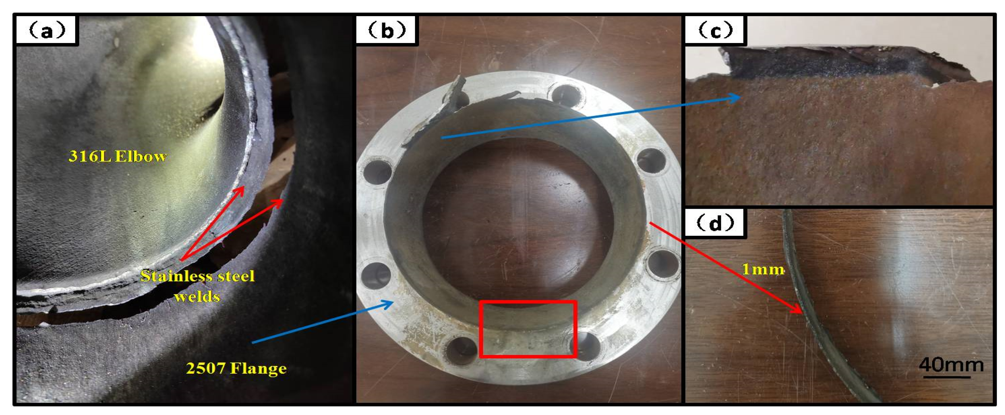
Figure 3.
Metallographic organization: (a) corroded flange; and (b) new flange.
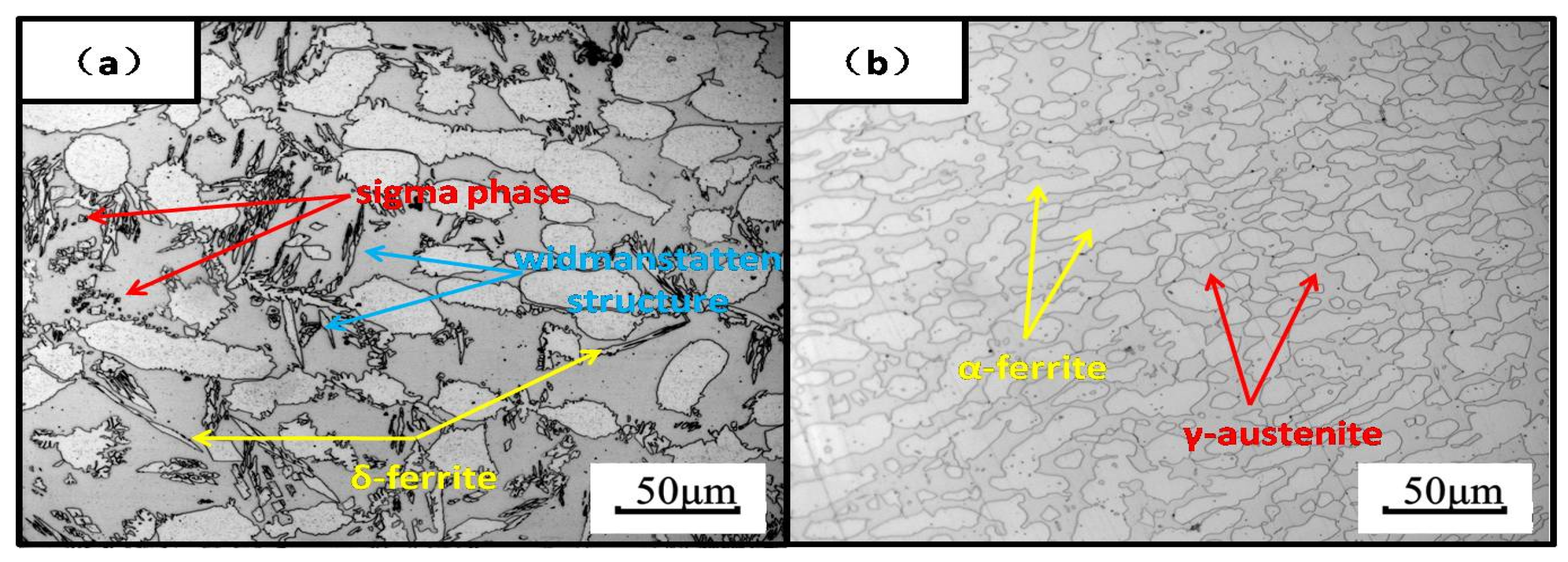
Figure 4.
Electron metallographic and spectroscopic results.

Figure 5.
Micro-morphology and energy spectrum: (a) flange corrosion site; (b) weld corrosion site; and (c) energy spectrum region.
Figure 5.
Micro-morphology and energy spectrum: (a) flange corrosion site; (b) weld corrosion site; and (c) energy spectrum region.

Figure 6.
Bending test results after the intergranular corrosion test: (a) corroded flange; and(b) new flange.
Figure 6.
Bending test results after the intergranular corrosion test: (a) corroded flange; and(b) new flange.

Figure 7.
Effect of pH on thecorrosion of NH4HS [41].
Figure 7.
Effect of pH on thecorrosion of NH4HS [41].


Table 1.
Heat exchanger-related parameters.
| Design Pressure (MPa) | Design Temperature (°C) | Operating Pressure (MPa) | Operating Temperature (°C) | ||||
|---|---|---|---|---|---|---|---|
| Shell Range | Tube Range | Shell Range | Tube Range | Shell Range | Tube Range | Shell Range | Tube Range |
| 0.83 | 0.67 | 183 | 80 | 0.39 | 0.3 | 35 | 30 |
Table 2.
Chemical composition analysis results (wt.%).
| Element | C | Si | Mn | P | S | Cr | Mo | Ni | N |
|---|---|---|---|---|---|---|---|---|---|
| Corroded flanges | 0.024 | 0.56 | 0.92 | 0.035 | 0.001 | 24.57 | 3.59 | 6.94 | 0.26 |
| New flanges | 0.025 | 0.55 | 0.93 | 0.034 | 0.001 | 24.66 | 3.55 | 6.98 | 0.25 |
| S2507 | ≤0.03 | ≤0.08 | ≤1.20 | ≤0.035 | ≤0.020 | 24.00~26.00 | 3~5 | 6~8 | 0.24~0.32 |
Table 3.
Energy spectrum results (wt%).
| Element | C | O | Na | Si | P | Mo | S | Ca | Cr | Mn | Fe | Ni | K |
|---|---|---|---|---|---|---|---|---|---|---|---|---|---|
| 1 | 29.55 | 15.19 | 0.87 | 0.35 | 0.51 | 3.8 | 2.73 | 0.47 | 10.88 | 0.65 | 32.55 | 2.44 | - |
| 2 | 35.92 | 13.88 | 0.67 | 0.37 | 0.56 | 4.34 | 6.05 | - | 7.48 | 0.67 | 27.63 | 1.99 | 0.46 |
| 3 | 16.97 | 4.36 | - | 0.83 | - | 2.72 | - | - | 20.04 | 1.1 | 48.66 | 5.32 | - |
Table 4.
Intergranular corrosion test conditions.
| Test Sample | Number of Samples | Sample Size (mm) | Test Solution | Sensitization System | Testing Time/h | Bending Angle/° |
|---|---|---|---|---|---|---|
| Corrosion flange | 4 | 58×20×3 | Cu-CuSO4−35%H2SO4 (microboil) | 700 °C Holding 30 min, water cooling | 20 | 90 |
| New flange | 4 | 80×16×3 |
Table 5.
Heat exchanger shell stroke inlet and outlet media compositions (%).
| Medium | NH3 | H2S | CO2 | H2O | Hydrocarbons |
|---|---|---|---|---|---|
| Crude ammonia (inlet) | 80.86 | 8.94 | 0 | 10.20 | 0 |
| Crude ammonia (exits) | 95.04 | 3.92 | 0 | 1.04 | 0 |
| Condensate (exits) | 36.74 | 24.56 | 0 | 38.70 | 0 |
Disclaimer/Publisher’s Note: The statements, opinions and data contained in all publications are solely those of the individual author(s) and contributor(s) and not of MDPI and/or the editor(s). MDPI and/or the editor(s) disclaim responsibility for any injury to people or property resulting from any ideas, methods, instructions or products referred to in the content. |
© 2024 by the authors. Licensee MDPI, Basel, Switzerland. This article is an open access article distributed under the terms and conditions of the Creative Commons Attribution (CC BY) license (https://creativecommons.org/licenses/by/4.0/).
Share and Cite
MDPI and ACS Style
Liang, H.; Duan, Z.; Li, W. Analysis of Causes and Protective Measures against Corrosion Perforation in the Shell-Side Outlet Flange of a Sour Water Steam Heater. Coatings 2024, 14, 306. https://doi.org/10.3390/coatings14030306
AMA Style
Liang H, Duan Z, Li W. Analysis of Causes and Protective Measures against Corrosion Perforation in the Shell-Side Outlet Flange of a Sour Water Steam Heater. Coatings. 2024; 14(3):306. https://doi.org/10.3390/coatings14030306
Chicago/Turabian StyleLiang, Haiming, Zhihong Duan, and Weiming Li. 2024. "Analysis of Causes and Protective Measures against Corrosion Perforation in the Shell-Side Outlet Flange of a Sour Water Steam Heater" Coatings 14, no. 3: 306. https://doi.org/10.3390/coatings14030306
Note that from the first issue of 2016, this journal uses article numbers instead of page numbers. See further details here.