
Review of the Progress of Energy Saving of Hydraulic Control Systems
by
Ruichuan Li
1,
Yisheng Zhang
1,
Zhen Feng
2,
Jikang Xu
3,*,
Xiaowei Wu
4,
Mengnan Liu
5,
Yuhai Xia
6,
Qiyou Sun
1 and
Wentao Yuan
1 1
School of Mechanical Engineering, Qilu University of Technology (Shandong Academy of Sciences), Jinan 250353, China
2
Department of Mechanical & Electrical Engineering, Rizhao Polytechnic, Rizhao 276800, China
3
College of Mechanical & Electrical Engineering, Qingdao Agricultural University, Qingdao 266109, China
4
Weichai Lovol Intelligent Agricultural Technology Co., Ltd., Weifang 261200, China
5
State Key Laboratory of Intelligent Agricultural Power Equipment, Luoyang 471000, China
6
Shandong Institute of Machinery Design & Research, Jinan 250353, China
*
Author to whom correspondence should be addressed.
Processes 2023, 11(12), 3304; https://doi.org/10.3390/pr11123304
Submission received: 23 October 2023
/
Revised: 3 November 2023
/
Accepted: 22 November 2023
/
Published: 27 November 2023
(This article belongs to the Special Issue Advanced Simulation and Experiment Methods of Flow Instability in Hydraulic Machinery)
Abstract
:In many different industrial domains, hydraulic control systems are extensively utilized. This paper examines the current state of research and the trajectory of energy-efficient hydraulic control system development. Initially, a quick introduction to the control principles of hydraulic control systems is given. Secondly, hydraulic control systems are classified, the factors affecting the energy consumption of hydraulic control systems are analyzed, and the method of reducing its influence on hydraulic control systems is given. Subsequently, research concerning energy conservation is compiled based on the classification of hydraulic control systems. In this paper, the circuit structure of two control modes of a hydraulic control system (valve control system and pump control system) and their related control algorithms (fuzzy PID control, adaptive robust control) for reducing system energy consumption are studied. In summary, the evolution of energy-efficient hydraulic control system approaches is forecasted and projected, offering some pointers for advancing hydraulic control system study and implementation in the industrial future.
1. Introduction
With the rapid development of the global economy and the continuous improvement of human living standards and quality of life, human demand for energy is also rising at an alarming rate. More than three-quarters of the world’s population lives in countries where the rate of ecological degradation exceeds the rate of self-renewal, and the issue of sustainable energy supply has become and will remain a hot topic for a long time. Due to its many applications in the fields of aviation, aerospace, ships, weapons, engineering machinery, and other related industries, hydraulic control systems have grown in importance as a technical force in the advancement of machinery and equipment development. They offer the advantages of high power, fast response, high precision, and large rigidity [1,2].
Hydraulic control system development has been a protracted process. Additionally, hydraulic control systems are continuously evolving and improving thanks to the tireless work of numerous academics and specialists. The water clock, the earliest hydraulic servo system ever created by humans, was created in 240 BC by an Egyptian, beginning the history of hydraulic control technology. However, in the long historical period that followed, hydraulic control technology remained sluggish until the late 18th and early 19th centuries, when there were some major advances. Hydraulic control technology advanced rapidly on the eve of World War II in response to the demands of industrial development; many of the early control valve concepts and patents came from this period. The first hydraulic servo systems with single-stage open-loop control valves controlled by solenoids debuted around the close of World War II. In the early 1950s of the 20th century, a fast-responding permanent magnet torque motor appeared, which was combined with a spool valve to form an electro-hydraulic servo valve. At the end of the 1950s of the 20th century, electro-hydraulic servo valves with nozzle baffles as the pilot stage appeared, which further improved the control performance. Since then, various new structures of electro-hydraulic servo valves have been introduced one after another, and their performance is becoming increasingly superior. Algorithms including adaptive fuzzy PID control, robust control, and composite control have progressively been applied to hydraulic control systems since the 20th century as a result of the advancement of electronic components and artificial intelligence. Hydraulic control technology has become the basic technical composition of modern mechanical equipment and devices, the basic technical element of modern control engineering, and an important means of industrial and national defense automation, and the degree of application of hydraulic control technology has become an important symbol to measure the level of industrialization of a country [3,4,5,6,7].
Hydraulic control systems adjust the flow direction, pressure, and flow of the oil in hydraulic control systems, so that the actuator and its driven working mechanism obtain the required direction of movement, thrust (torque), and movement speed. The accuracy of hydraulic control systems is typically difficult to guarantee because of nonlinear factors such as leakage, contaminants, processing mistakes, and component degradation [8,9,10]. This paper analyzes the development process and research significance of hydraulic control systems, studies the progress of two control methods of a hydraulic control system and related intelligent control algorithms for reducing energy consumption, analyzes the causes of energy loss of hydraulic control system, and summarizes the relevant research of domestic and foreign scholars on solving the energy loss of hydraulic control systems. Finally, on the basis of the above research, the development trend of hydraulic control systems is predicted, and their development prospect is prospected. Based on the assumption that a hydraulic control system’s control accuracy must be guaranteed, the research presented in this paper has some relevance for lowering a hydraulic control system’s energy consumption and can be used as a guide for improving hydraulic circuits and control strategies.
2. Working Principle of Hydraulic Control System
Hydraulic control systems are a feedback control system that uses hydraulic components as control and execution components, and hydraulic oil as the working medium for energy transmission. The movement of hydraulic actuators refers to the system output (including displacement, velocity, acceleration, and force), which is transmitted to the controller through feedback components. The input signal of the control component is adjusted according to the error size, so that the system output can automatically, quickly, and accurately track the system input instructions. Hydraulic control systems are classified into pump-controlled hydraulic control systems and valve-controlled hydraulic control systems based on their various control modes and valve components [11,12,13].
2.1. The Working Principle of the Valve Control System
By regulating the hydraulic valve’s (proportional, servo, and other) valve opening, the valve control system regulates the actuator’s speed. The control components of valve control systems are generally servo valves or proportional valves, as they can reach and maintain any intermediate valve core position. This can control the size of the throttling gap, thereby controlling the flow through the throttling gap. This type of valve, especially the servo valve, often works together with the bypass valve to form a series of connected throttling control system structure. There are two types of throttle control methods in valve control systems. One is the series throttle control method, where a portion of the flow generated by the quantitative pump is returned to the oil tank through the overflow valve. Another method is parallel throttle control, where a portion of the flow generated by the quantitative pump enters the hydraulic receiver through the throttle valve, and in this case, the safety valve does not work. Therefore, not all of the oil output from the quantitative pump is used to control the speed of the actuator, resulting in lower system efficiency and higher system heat generation. This makes valve control systems generally only applicable in scenarios where the speed of the actuator changes significantly and the control accuracy requirements are not high [14,15,16,17].
The valve control system adjusts and controls parameters such as pressure, flow rate, and direction of the hydraulic system by controlling the switch state of the hydraulic valve. Figure 1 shows the control block diagram of a typical electro-hydraulic proportional valve control hydraulic system. The electro-hydraulic proportional valve control system here outputs a current signal from the control system center, adjusts the servo valve opening through the action of a servo amplifier, sets the required pressure for the hydraulic system, and transmits it to the control system center through a pressure sensor. The control system center collects the actual output pressure, corrects it by comparing and analyzing it with the previously set values. Then, the obtained correction signal is analyzed as the stable output pressure of the system to ensure that the control system reaches the required pressure for the hydraulic system [18,19,20].
Figure 2 shows the schematic diagram of the electro-hydraulic proportional valve-controlled hydraulic system. The operator first sets the system oil pressure target value, and the hydraulic oil in the tank is output by the oil pump. Currently, the directional valve is positioned correctly among the three locations. The main purpose of this is to convert the hydraulic energy of the hydraulic oil in the hydraulic cylinder into mechanical energy, and then use a pressure sensor to measure the hydraulic oil pressure of the system. Under the action of an A/D converter, the analog signal is converted into a digital signal and transmitted to the system. The system obtains a set of values by subtracting the target value of oil pressure from the obtained digital signal value. The difference in the obtained signal is converted and transmitted to the electro-hydraulic proportional relief valve, and the valve opening of the relief valve is adjusted to adjust the amount of hydraulic oil entering the hydraulic cylinder, thereby accurately controlling the internal oil pressure of the jack. The fundamental functions of the entire hydraulic system are to regulate the hydraulic cylinder’s displacement by the amount of oil it receives, alter the proportional relief valve’s opening area through the input current signal, and, in the end, use the cylinder’s displacement to calculate the system pressure [21,22].
2.2. The Working Principle of the Pump Control System
Volume control is another name for the pump-controlled hydraulic control system. Each actuator receives the same amount of oil input thanks to the pump-controlled hydraulic control system, which regulates actuator movement by varying the displacement of the hydraulic variable pump. Pump-controlled hydraulic control systems, as opposed to valve-controlled hydraulic control systems, use hydraulic variable displacement pumps to control actuator components, which reduces the number of hydraulic valves and the configuration of hydraulic pipelines. This improves system efficiency and considerably lowers energy losses associated with overflow throttling loss, hydraulic oil leakage, and frictional heat. The inherent frequency of the pump control system is therefore substantially lower than that of the valve control system under identical circumstances, which causes the pump control system to respond slowly. With steady or little load variations, the pump-controlled hydraulic synchronous system may achieve very tiny errors and has a high volumetric efficiency. Table 1 shows the differences between pump control systems and valve control systems [23,24,25,26,27,28]. The main difference between valve control systems and pump control systems is that the control components of valve control systems are generally proportional valves or servo valves, while the control components of pump control systems are hydraulic variable displacement pumps.
The pump control system adjusts and controls the pressure, flow, and direction parameters of the hydraulic system by controlling the operating status and flow rate of the hydraulic variable pump. Figure 3 shows the control block diagram of a typical electro-hydraulic proportional pump control hydraulic system. Compared with the electro-hydraulic proportional valve-controlled hydraulic system, the electro-hydraulic proportional pump control system here has an additional feedback path, and the sensor can collect the pressure and flow parameters in the system in real time, so that the system can change the instructions of the command device according to the working conditions, and can find problems and abnormalities in the system in time to improve the system efficiency [29,30].
The pump control system realizes the adjustment and control of the pressure, flow, direction and other parameters of hydraulic control systems by controlling the operating state and flow of the hydraulic variable pump. Pump control systems typically consist of hydraulic variable pumps, hydraulic valves, actuators, and controllers. The principle of a typical pump control system is shown in Figure 4. In a pump-controlled system, the hydraulic variable displacement pump is responsible for providing hydraulic energy, pumping the hydraulic oil from the hydraulic tank and delivering it to the hydraulic valve through the line. Based on the input of a control signal, the hydraulic valve modifies the actuator’s movement state by controlling the hydraulic pump’s flow and start/stop functions. The actuator can be a hydraulic cylinder or a hydraulic motor that enables linear or rotary motion through the action of hydraulic oil. The controller is responsible for receiving and processing input control signals and sending control commands to hydraulic valves and hydraulic pumps to realize automatic control of the system [31,32,33].
3. Factors Affecting Power Loss in Hydraulic Control Systems and Energy-Saving Measures
The purpose of energy conservation is to improve energy utilization, reduce energy waste, and ensure the required energy output with the least amount of energy input. Efficiency is the main indicator of energy utilization during system operation, which is the ratio of system output power to input power [34,35]. When the effectiveness of the hydraulic system is enhanced by the efficiency of the prime mover powering the hydraulic pump, the overall effectiveness of hydraulic control systems becomes:
η = ηeηcηtηm
In the equation, ηe is the efficiency of the prime mover, and its value is the output power of the prime mover. That is, the ratio of the output power of the hydraulic pump to the input power.
ηc is the efficiency of conversion, it represents the ratio between the output power and the input power of the energy conversion element in hydraulic control systems, that is, the efficiency of the energy conversion element itself, such as a hydraulic cylinder or hydraulic motor.
ηt is transmission efficiency, liquid flow can cause energy loss, which is partly necessary for the hydraulic system to achieve control functions, such as pressure loss at valve ports such as throttle valves and directional valves. The other part is unnecessary additional losses, such as pressure loss caused by wall friction resistance when liquid flows in a long straight pipeline; but, it is often difficult to completely separate the two, and the transmission efficiency comprehensively considers the degree of total loss of the two types of pressure during the liquid transmission process.
ηm is the matching efficiency, which is the ratio of the input power required by the actuator to the output power of the hydraulic pump after removing transmission losses.
From the calculation formula of the total efficiency of hydraulic control systems, it can be seen that the energy loss generated by hydraulic control systems [36,37,38,39] mainly includes the following four aspects of energy loss:
- (1)
- Energy conversion loss
Energy conversion loss refers to the loss caused by energy conversion components in hydraulic control systems during energy conversion, including mechanical friction loss, pressure loss, and volume loss. For example, a hydraulic pump converts the mechanical energy input from the prime mover into the hydraulic energy output. During the energy conversion process, there is mechanical friction loss on the shaft and volume loss caused by internal leakage of the pump. The hydraulic motor converts the input hydraulic energy into the output mechanical energy, and there are also mechanical friction losses on the output shaft of the hydraulic motor and volume losses caused by internal leakage of the motor during the conversion process. The energy conversion loss is not only related to the type of energy conversion element, but also to factors such as operating conditions and wear.
- (2)
- Energy transmission loss
Energy transmission loss refers to the energy loss generated by the hydraulic working medium during transmission throughout the entire hydraulic system, namely flow loss. It depends on the structure and layout of other components besides energy conversion components, such as the structure of control components, the type and layout of auxiliary components such as accumulators, the connection method of pipelines between each component, and the type, quantity, size, etc. of joints and pipelines.
- (3)
- Energy-matching loss
Energy-matching loss is the energy loss caused by the mismatch between the energy provided by the power source (usually an electric motor) of a hydraulic control system and the energy required by the load. Due to the complex working conditions of hydraulic control systems, the output power of the motor cannot be stabilized within the optimal economic range, resulting in high energy issues. In addition, due to power fluctuations, it is difficult for the electric motor to match the power demand of the hydraulic pump in real-time. When the output power of the electric motor exceeds the required power of the hydraulic system, excess energy is wasted through overflow and thermal energy; when the power output from the motor is lower than the power required by hydraulic control systems, the torque output of the motor is lower than the torque required by the hydraulic pump for normal operation, which will lead to a decrease in the speed of the motor, thereby increasing the energy consumption of hydraulic control systems.
- (4)
- Energy loss caused by impact
The impact pressure may reach 3–4 times the normal working pressure, causing damage to components, pipelines, instruments, etc. in the system; the impact pressure generated by the impact causes the pressure relay to missignal, interferes with the normal operation of the hydraulic system, and affects the stability and reliability of the hydraulic system, causing vibration and noise, loosening of connections, oil leakage, changing pressure regulation by pressure valves, and changing flow regulation by flow valves; this affects the normal operation of the system.
For the four types of energy losses mentioned above, the energy consumption of the system can be reduced by using the following methods [40,41,42,43,44]:
- (1)
- Improving the efficiency of hydraulic components and reducing energy loss in controlling them
This can mainly be achieved by improving the quality of components and developing new energy-saving components. For example, by optimizing the design of electromagnets that drive electromagnetic directional valves to reduce the power consumption of electrical control components, by optimizing the flow channels of various hydraulic valve ports to reduce the pressure loss of oil flowing through the valve ports, and by designing reasonable clearance to reduce leakage, energy-saving methods can be achieved.
- (2)
- Improve the matching relationship of energy
This is mainly achieved by reducing the friction torque of the output shaft of the prime mover to improve the power-matching relationship between the two, in order to improve the operational efficiency of the prime mover. Reducing the excess power between hydraulic pumps and the loads includes reducing pressure excess and flow excess. Reducing excess pressure can be achieved by trying to match the supply pressure of the hydraulic pump with the required load force, and reducing excess flow can also be achieved by trying to match the supply flow of the hydraulic pump with the required flow of the load.
- (3)
- Reduce pressure loss during transmission
Pressure loss is usually caused by viscous friction, vortex formation, and sudden changes in flow direction and cross-sectional area, including pressure loss in hydraulic pipelines and pressure loss at pipe joints. Pipeline pressure loss can be reduced by selecting a reasonable inner diameter pipeline to reduce pipeline heating and thus reduce pressure loss; reducing the pressure loss along the way can be achieved by making the structural design of the entire hydraulic system as compact as possible and minimizing the length of the pipeline.
- (4)
- Reduce the vibration generated during equipment startup
① Add a more suitable coupling between the active and driven shafts of the equipment. A coupling is a mechanical component used to connect the active and driven shafts in different mechanisms and rotate them together, transmitting motion and torque. In addition to transmitting motion, the coupling can also compensate for the displacement (including axial displacement, radial displacement, angular displacement, or comprehensive displacement) between two shafts due to inaccurate manufacturing and installation, deformation during operation, or thermal expansion, alleviating impact and vibration absorption, and playing an overload protection role to achieve stable motion transmission.
② Reduce interference from proportional valves. Hysteresis is an important static indicator of proportional valves, and the presence of hysteresis can reduce the repetitive accuracy of open-loop control systems. For closed-loop control systems, excessive hysteresis of the proportional valve can lead to system vibration and closed-loop control failure. The hysteresis loop mainly comes from the frictional force between the valve core and valve body, as well as static hydraulic force. For direct drive valves driven by proportional electromagnets, the hysteresis and friction hysteresis of proportional electromagnets are also important sources of hysteresis in proportional valves. The following methods can reduce the hysteresis of the proportional valve: reasonable clearance and shape accuracy of the valve core and valve hole. Choose a reasonable working air gap and non-working air gap size for proportional electromagnets, and control the coaxiality between the iron core and guide sleeve. The use of valve core displacement closed loop can significantly reduce the hysteresis of the proportional valve (<1%). The open-loop control proportional valve superimposes chatter on the coil driving the current. Here is the Summary of factors affecting power loss and energy-saving measures (Table 2).
4. Current Status of Energy-Saving Research on Hydraulic Control Systems
The above energy loss analysis shows that a portion of the energy loss is caused by the system’s own structure, such as motor transmission efficiency loss, hydraulic pump efficiency loss, and hydraulic pipeline loss. This part can only be reduced as much as possible by improving the product structure design. Another part is the energy loss caused by the complex and variable operating conditions, such as hydraulic control system overflow loss, pressure loss, etc., which make it difficult for the engine output power to fully match the load demand. This part can be achieved by optimizing the control strategy of the system to achieve the required state for operation [45,46].
At present, there are two main types of hydraulic control systems: the valve control system and the pump control system. The valve control system has the advantages of good dynamic characteristics and fast response speed, but due to the use of throttling control, overflow and throttling losses are large, resulting in low energy efficiency; in high-power systems, valve control systems require a large number of valve groups for system control, resulting in significant throttling losses. The improvement methods of valve control systems mainly focus on two aspects: the improvement of hydraulic circuits and the optimization of control strategies. For the problems of low system efficiency, system connection loss, and load step disturbance in hydraulic control systems, these types of problems are mainly caused by the components of the system itself. They can be improved by optimizing the hydraulic circuit to reduce the impact of these problems on system performance; for the problems of motor load fluctuation, time delay, and nonlinearity caused by unknown initial values in hydraulic control systems, these types of problems can be solved by changing the control strategy of the original system [47,48].
The pump control system belongs to the volume control system, and the output flow of the pump is matched with the working pressure, without throttling and overflow losses. Therefore, the transmission efficiency is high, but there are problems such as slow dynamic response and poor low-speed characteristics. The improvement methods of the pump control system mainly focus on two aspects: the improvement of the hydraulic circuit and the optimization of the control strategy. For the problems of asymmetric flow and nonlinearity in hydraulic control systems, which are caused by defects in the system composition, improvements can be made by optimizing the hydraulic circuit to reduce the impact of these problems on system energy loss; for problems such as low steering accuracy, tracking of system uncertainty, external load disturbance, and nonlinear flexible transmission laws in hydraulic control systems, these problems are caused by the algorithm of control system components and can be solved by changing the control strategy of the original system [49,50].
4.1. Current Research Status of Energy-Saving Circuits and Structures in Hydraulic Control Systems
The traditional approach to various power losses in hydraulic control systems is mainly focused on improving the circuit and structure of hydraulic control systems. The valve control system in hydraulic control systems suffers energy loss due to throttling losses, while the pump control system suffers energy loss due to problems such as slow dynamic response and poor low-speed characteristics caused by nonlinearity in the system.
4.1.1. Current Research Status of Energy-Saving Circuits and Structures in Valve Control Systems
In order to maintain high efficiency and achieve rapid adjustment of the high-power hydraulic speed control system under load step disturbances, Sato et al. [51] proposed a bypass valve-controlled hydraulic motor speed control system (as shown in Figure 5). This system achieves rapid adjustment through valve-controlled leakage, which increases the damping of the system and improves its stability. However, the system has problems such as poor speed stiffness and high energy consumption; Sheng et al. [52] improved the bypass valve-controlled hydraulic motor speed control system by adding independent oil supply energy to the valve-controlled branch. The bypass servo valve is always in the state of replenishing oil to the system. Compared to not adding independent oil supply energy, the system’s response speed was improved by 1.2 s, the system’s efficiency was increased by 24.5%, and the system’s energy saving was 36.7%.
In response to the issues of high noise and high energy consumption generated by heavy-duty construction machinery during operation, Bury et al. [53] conducted research on the transmission in valve control systems. Through simulation and experimental methods, it was found that by appropriately adjusting the parameters of the control signal provided to the proportional spool valve coil, the high load time of the hydraulic pump can be reduced, moreover, the maximum pressure value at the inlet of the hydraulic motor during startup can also be modified by adjusting the shape of the proportional spool valve control signal. It can also reduce the noise generated by the transmission during startup, prevent excessive wear of hydraulic components, enable construction machinery to quickly reach working conditions, increase normal operation time of construction machinery, reduce system energy loss, and effectively improve the efficiency of heavy-duty construction machinery. During the steering process of the loader, the hydraulic pump supplies oil to the steering system separately. Due to the fact that the working power of the steering is much lower than that of the lifting and turning bucket, the hydraulic pump is in a partial load condition, and the excess flow returns to the oil tank through the overflow valve, resulting in significant overflow loss; the oil provided by the hydraulic pump is distributed to the steering hydraulic cylinder through the steering valve, and the steering valve often uses a rotary valve with more throttling ports to achieve high-precision steering, resulting in a large amount of throttling loss. And the steering condition is the most frequent operating condition during the working process of the loader. Improving the energy efficiency of the steering system is one of the main methods to reduce the energy loss of the loader hydraulic system [54,55]. Dell et al. conducted research on the steering system of loaders, replacing the original steering valve with four electric proportional valves. By collecting real-time steering wheel torque and hydraulic cylinder pressure signals during the steering process to control the opening and closing of the hydraulic valve, the overflow loss that existed during the steering process was eliminated and the throttling loss was reduced. Compared with traditional steering systems, the energy loss was reduced by 2.3 times, improving the machine’s productivity by 22.6%; not only does it reduce the energy consumption of the steering system, but it also improves the stability during the steering process [56,57]. Zhao et al. [58] proposed a valve-controlled hydraulic energy-saving system based on a hydraulic transformer to address the problem of low energy utilization efficiency in the valve-controlled hydraulic system of hydraulic excavators and studied its energy-saving effect. They studied the energy consumption of valve-controlled hydraulic systems and valve-controlled hydraulic energy-saving systems based on hydraulic transformers in AMESim and AMESim MATLAB environments, respectively, and compared and analyzed the energy utilization efficiency and energy-saving effect of the valve-controlled hydraulic system and the valve-controlled hydraulic energy-saving system. After simulation verification, the simulation results displayed that the valve-controlled hydraulic energy-saving system using hydraulic transformers as the main control component has good dynamic performance, and the energy utilization rate is significantly improved compared to the valve-controlled hydraulic system. The system saves 35.63% of energy, and the energy-saving effect is excellent.
Hydraulic control systems have the advantages of high load, high stiffness, high power to weight ratio, and high technological maturity. Based on the above advantages of hydraulic control systems, hydraulic brakes are still the mainstream of anti-skid brake control hydraulic actuation for military and civilian aircrafts. The performance of the anti-slip braking system directly affects the aircraft’s rapid response, safe return, takeoff, and sustained combat capabilities, thereby affecting the overall performance of the aircraft. Due to the short duration of the aircraft landing process (about 20 s), the anti-slip braking system must be safe, reliable, and responsive to ensure that the aircraft can brake safely. When vibration occurs in the aircraft brake control system, it can cause discomfort to the driver and passengers, and in severe cases, damage to the landing gear and serious safety accidents [59,60]. Regarding this issue, Q Cao et al. [61] established a finite element model of aircraft brake discs and analyzed their instability frequency. Most of the research on aircraft brake vibration both domestically and internationally focuses on friction between dynamic and static brake discs, brake system control rate, and anti-slip system chatter. However, there is little research on the characteristics, vibration, and vibration suppression methods of the brake pressure servo valve actuator system in wheel brake devices. Zhang [62] revealed the mechanism behind nonlinear self-excited oscillation in the brake pressure servo valve control cylinder system, clarified the influence of key parameters in the system on the dynamic behavior of nonlinear self-excited oscillation, and proposed effective vibration suppression measures for the brake pressure servo valve control cylinder system. Based on the fundamental principle of completely eliminating the positive feedback phenomenon of oil return, a new type of two-stage brake pressure servo valve structure was optimized. The experimental results showed that under various operating conditions, the fluctuation range of the brake pressure output by the new valve only needs to be within 0.1 MPa, and the system has no resonance.
Wrat G et al. [63] addressed the low efficiency of hydraulic systems caused by throttling, overflow, and other issues in linear actuators commonly found in construction machinery. Therefore, they implemented energy-saving position control using two different hydraulic circuits and compared their efficiency. The first hydraulic circuit uses a conventional proportional directional control valve for position control, while the second hydraulic circuit adopts an innovative solution of flow control valves and evaluates the efficiency of the system by creating artificial leaks at both ends of the actuator. During the control process, the additional flow of the pump can be discharged through the flow control valve, reducing energy loss and improving the efficiency of the electro-hydraulic servo system. The experimental results show that the circuit using flow control valves saves 8.5% energy compared to the traditional circuit using proportional directional control valves. For the energy-saving analysis of the system, in addition to analyzing the circuit structure, it should also be analyzed from the perspective of connection loss and angle fittings. Karpenko et al. [64] studied the pipeline system through simulation, using equivalent length straight pipes, pipes connected to 45-degree angle fittings, and pipes connected to 90-degree angle fittings to compare with their corresponding K-shaped pipes. The simulation results show that the pipeline connected by 90-degree fittings has the highest power loss, with a power loss range of 5.22–10.3–16.261 W; the power loss of the pipeline connected to the 45-degree angle fitting is the second, with a power loss range of 3.81–10.3–13.438 W; the power loss of equivalent length straight tubes is not significant, and the range of power loss is 1.52–10–3–11.177 W; this indicates that reducing the use of bent pipes can reduce the energy loss of the system.
4.1.2. Current Research Status of Energy-Saving Circuits and Structures in Pump Control Systems
The pump control system mainly faces problems such as imbalanced flow and nonlinearity. Scholars have optimized the pump-controlled asymmetric cylinder system for issues such as asymmetric flow caused by the difference in hydraulic cylinder area, starting from the hydraulic circuit. Ma et al. [65] proposed two schemes: using a hydraulic transformer and using two variable displacement pumps driven by coaxial to compensate for the asymmetric flow caused by the difference in hydraulic cylinder area. Rahmfeld et al. [66] conducted in-depth research on a pump control system that uses hydraulic control one-way valves to compensate for asymmetric flow and designed a hybrid pump control system for the entire excavator. The load potential energy was recovered through an auxiliary pump/motor coaxial connected to a closed hydraulic pump and torque coupling. Compared with the original system, the system’s energy consumption was reduced by 50%. Ni et al. [67] proposed a new linear driving principle that combines closed pump control rotation with mechanical linear conversion. Through theoretical analysis and simulation, this method allows the variable displacement pump to operate at large displacement, medium to high speed, and the system can maintain high efficiency over a large load range, with an efficiency of 60%−68%. However, this method has not been experimentally verified. Zhang et al. [68] designed a new type of three-port hydraulic pump, changing the flow distribution window of the hydraulic pump from 2 to 3. The flow distribution window was used to balance the asymmetric flow of the system, and the hydraulic pump was used to drive the excavator bucket rod, achieving good control characteristics and energy-saving effects. Wang et al. [69] proposed the circuit principle of using a hydraulic transformer and two hydraulic pumps driven by a shaft to compensate for the asymmetric flow of the differential cylinder. The differential flow is balanced by a hydraulic transformer, and this system uses a large number of hydraulic pumps with complex structures and high installation costs. Chen et al. [70] used two variable displacement pumps driven in parallel to compensate for the asymmetric flow of the hydraulic cylinder and added an accumulator to balance the load weight and recover gravitational potential energy. Yao et al. [71] proposed an open-pump control principle that uses two coaxial-driven open hydraulic pumps to control the two chambers of the hydraulic cylinder and uses the displacement of the hydraulic pump to balance asymmetric flow. Wang et al. [72] designed a three-port pump-controlled asymmetric cylinder system, as shown in Figure 6. The new three-port pump balances the asymmetric flow of the hydraulic cylinder through a flow plate, without one-way throttling loss and unbalanced flow loss. Compared with the symmetric pump control system, the three-port pump control system can save 18.6% of energy, reduce energy loss by 32.43%, and achieve good energy-saving effects.
In response to the problem of asymmetric flow in the pump-controlled differential cylinder system, Gao et al. [73] used a hydraulic-controlled one-way valve to balance the asymmetric flow and applied it to the differential cylinder control circuit in engineering machinery. A variable pump control scheme is proposed for the hydraulic cylinder circuit in engineering machinery, where each variable pump is driven by the engine through different reducers. This scheme opens up a new way for the hydraulic pump to directly control the multi-actuator hydraulic circuit. The system principle is shown in Figure 7. Because the engine is driven by a reducer with a certain speed ratio, this scheme can only control the differential cylinder by changing the displacement of the variable displacement pump.
For the pump-controlled differential cylinder system, due to the uneven flow rate between the two chambers, Gao and Huang [74,75] proposed an asymmetric axial piston pump with three suction and discharge ports (as shown in Figure 8), which can compensate for the uneven flow rate between the two chambers. In order to further improve the energy efficiency of the pump-controlled differential cylinder system, the system is subjected to energy recovery and reuse. Add an accumulator to the system to achieve the recovery and reuse of gravitational potential energy. Wang et al. [76] established a mathematical model for the potential energy recovery process based on theoretical analysis by studying the potential energy recovery efficiency of the asymmetric pump control differential cylinder system and analyzed the influence of accumulator pressure on energy recovery efficiency; establish a physical simulation model for the potential energy recovery system and conduct simulation research on the potential energy recovery process. The results show that compared with ordinary airbag-type accumulators, using a constant pressure accumulator for energy recovery can avoid the possibility of asymmetric pumps transitioning from motor operating conditions to pump operating conditions during the potential energy recovery process, resulting in the inability to recover residual energy; when the load is 10 kN, the maximum energy-saving efficiency of using a constant pressure accumulator can reach 29.8%.
For the unbalanced flow rate of the system, Christopher et al. [77] used an auxiliary pump and accumulator to compensate through a hydraulic control one-way valve, and the system schematic is shown in Figure 9. The boom oil cylinder and the stick oil cylinder are directly controlled by two servo variable displacement pumps, which are driven by the engine through the shaft. Research has shown that the operating performance of loaders is good. Experimental studies have been conducted on loaders under both no-load and load conditions, and the full load acceleration is about 80% of the no-load acceleration, which is more than 30% energy-saving compared to valve control systems. In order to improve the control performance of the system, a two position two-way solenoid valve is added to each of the two chambers of the differential cylinder, which increases the complexity and energy consumption of the system.
To simplify the system principle, reduce installation costs, and automatically compensate for flow asymmetry caused by differential cylinder area difference, Zhang et al. [78] proposed a new hydraulic pump with a flow distribution principle. The pump has three oil ports, which are respectively connected to the rod chamber, rodless chamber, oil tank, or accumulator of the differential cylinder. Changing the area ratio of the flow distribution window corresponding to the three oil ports can automatically compensate for the asymmetric flow caused by the difference in area of the differential cylinder. The system principle is shown in Figure 10. At present, the flow rate of the pump in this system is controlled by changing the speed of the electric motor. For variable speed and constant displacement control, it has been applied in injection molding machines, and the control of the hydraulic pump displacement is still in the preliminary research stage.
In response to the problems of large inertia, slow system response, dead zone, and nonlinearity in the large closed-loop variable frequency control system, Xu et al. [79] and others studied the energy consumption characteristics of variable frequency volumetric speed control hydraulic elevators. By detecting the current value provided by the control board when the one-way valve is opened in the upstream stage, the leakage amount of the pump is determined, and then compensated in the program to obtain good control performance. In terms of energy consumption, compared to variable frequency valve-controlled variable speed hydraulic elevators, the average energy-saving rate of variable frequency volume-controlled hydraulic elevators should reach at least 70% [80].
4.2. Current Research Status of Energy-Saving Control Strategies for Hydraulic Control Systems
With the emergence of more hydraulic control technologies and the increasing emphasis on energy conservation in society, more attention is being paid to using advanced control methods to solve the problem of high energy consumption in electro-hydraulic servo systems. Domestic and foreign scholars have conducted various studies on energy-saving in electro-hydraulic servo systems [81].
4.2.1. Research Status of Energy-Saving Control Strategies for Valve Control Systems
The throttling loss of the valve control system during operation can cause the output power to not match the actual working conditions. There is still great room for improvement in the control performance of valve control systems. In order to improve energy efficiency, as the valves in the valve control system are directly driven by circuits, better control strategies are applied to the valve control system to match the output power of the system with actual working conditions, thereby achieving the goal of energy conservation [82,83].
The key to solving the problem of low cotton-picking efficiency caused by the operation of the cotton-picking head motor of the cotton-picking machine under load fluctuations is to study the constant speed control method of the valve-controlled motor hydraulic system. By solving this problem, the cotton-picking machine can achieve energy-saving and environmental protection during the cotton picking process. In response to the issues raised above, a single control strategy cannot effectively solve this problem. Mao et al. [84] proposed a fuzzy adaptive PID control strategy without manual intervention, which effectively improved the response speed and anti-interference ability of the valve control system. Jiang et al. [85] proposed an intelligent control method based on fuzzy neural network control of motor speed, which effectively improves the adaptive ability and robustness of valve-controlled motor systems. Dang et al. [86] used a robotic arm as the research object and adopted a fuzzy PID control method to improve the dynamic response ability and tracking characteristics of the valve-controlled motor system. Li et al. [87] established a simulation model to improve the control performance of the valve-controlled motor system by combining the anti-saturation PID control of variable structure and fuzzy PID control. Wang et al. [88] established a mathematical model for the speed control problem and improved the model by using the PID control strategy to improve the speed control accuracy of the valve-controlled vane air motor system. Yan et al. [89] proposed a dual channel equivalent cross-coupling synchronization control strategy for valve-controlled dual motor synchronization and combined it with PID control correction to improve response speed and stability accuracy. Yan [90] compared and analyzed the application effect of PID control and pole placement method in valve-controlled motor systems, as well as the influence of the pole position of the state observer on the dynamic characteristics of the system. Lei et al. [91] used PID and parameter self-tuning fuzzy PID control strategies to achieve constant speed control of hydraulic motors for electro-hydraulic proportional valve-controlled hydraulic motor systems. Simulation results showed that the fuzzy PID control effect was better. From the above analysis, it can be seen that for valve-controlled motor speed control systems, PID or its improved control algorithms are often used to improve the control effect to achieve the goal of energy conservation. Liu et al. [92] proposed a method based on load feedforward compensation and self disturbance rejection composite control of speed, which reduces the response time of the system by 23.3% under constant load step input; under the action of sudden load, the maximum overshoot of the motor output speed decreased by 66.7% and the stability time decreased by 59.6%. In response to issues such as power output fluctuations in the valve control system, Tian [93] conducted research on the control performance of the valve control motor speed control system using two control methods: ordinary PID control and neural network PID control. The results showed that compared to the ordinary PID control system, the overshoot of the neural network PID control system was reduced from 15% to 8%, and the adjustment time of output power was reduced from 1.75 s to 1.5 s. The control curve was smoother, and the power output was stable, effectively achieving the goal of energy conservation.
In response to the nonlinear problem caused by unknown initial control variables in hydraulic systems, Guan [94] proposed a nonlinear adaptive controller to compensate for nonlinear uncertain parameters, and ultimately achieved good control results. Xiong [95] proposed a data-driven adaptive control method based on an extended state observer to address the inherent nonlinear characteristics and structural uncertainty issues in valve-controlled electro-hydraulic servo rotary systems. Using optimal theory, he proposed a time-varying parameter update algorithm and a data-driven adaptive control law. The tracking error convergence of the system was verified. In response to the problem of backlash nonlinearity in the valve-controlled hydraulic motor system of rocket weapons, Zhao [96] designed an adaptive robust control algorithm to compensate for backlash nonlinearity and improve system performance. For the problem of dynamic asymmetry in the valve-controlled asymmetric cylinder electro-hydraulic position servo system, Mu [97] designed an adaptive control system based on Lyapunov stability theory and applied it to the valve-controlled asymmetric cylinder electro-hydraulic position servo system. When the step response time of the system is shortened to 100 ms of the model response time, a constant external interference is applied to the system, and the system can quickly make adjustments and has high robustness.
4.2.2. Current Research Status of Energy-Saving Control Strategies for Pump Control Systems
The nonlinearity and uncertainty of the pump control system during operation can lead to a mismatch between the power source and the actual working conditions. The efficiency of the power source is only about 75%, and there is still great room for improvement in the control performance of the hydraulic system. In order to improve energy efficiency, as the pumps in the pump control system are directly driven by circuits, better control strategies are applied to the pump control system to match the power source of the system with the actual working conditions, thus achieving the goal of energy conservation.
In response to the problems of high energy consumption and low steering accuracy in traditional agricultural machinery hydraulic systems, Wang et al. [98] proposed to use the difference between the target displacement value of the cylinder and the actual displacement value of the cylinder as the input of the PID controller. By controlling the opening of the electromagnetic proportional valve through the PID controller, the control accuracy and response characteristics of the tractor hydraulic system are improved. Wen et al. [99] proposed a dual closed-loop PID road-sensing system control strategy, which significantly improves the smoothness of the hydraulic system’s step response torque input and the following performance of the triangular input, reducing the system’s response time. Diao et al. [100] used a fuzzy immune PID controller to control the tractor’s wire-controlled steering, achieving a response time of 0.272 s under step response. Ma et al. [101] proposed the use of a deep plowing fuzzy PID automatic control strategy. Through simulation, it can be seen that the proposed control strategy can improve the control accuracy of the tractor electro-hydraulic suspension system under deep plowing conditions.
In response to the tracking problem of nonlinearity and uncertainty in hydraulic servo pump control systems, Li et al. [102] combined the time optimal and the Lyapunov function and proposed an improved second-order approximate time optimal control algorithm. By using this control algorithm, while ensuring robustness, the response speed of the second-order sliding mode can be significantly improved and chattering can be effectively suppressed. In response to the nonlinearity and time delay of the variable speed pump control hydraulic system of the boom, Huang [103] designed a BP neural network PID controller for the variable speed pump control hydraulic system of the boom. The maximum displacement tracking error of the system is 0.92 mm, and the error is within 1 mm. However, using only ordinary PID control, the maximum error of the system is 3.39 mm, and the error is 2.11 mm. From this, it can be seen that the system control effect using BP neural network PID controller is significantly superior to ordinary PID control.
In order to improve the control effect of the hydraulic system of engineering vehicles during the construction process, Kan et al. [104] proposed a hybrid fuzzy PID control algorithm. The common components in the mechanical hydraulic system of engineering vehicles were selected and the pump-controlled motor speed control system was used to construct a mathematical model for it. Simulation experiments were conducted using MATLAB (https://www.mathworks.com). The results showed that during the initial acceleration stage and the load action stage, the fuzzy PID control strategy is used to improve the control process of the system, and the maximum overshoot of the two levels is reduced by 48.05% and 40.01%, respectively, and reduced the time required to reach a stable state by 20.18% and 26.71%, respectively. Zhang et al. [105] proposed a direct drive dual pump-controlled three-chamber cylinder system based on speed feedforward and fuzzy PID composite control to address the potential energy loss of the boom during the working process of hydraulic excavators and applied the proposed system to the excavator boom. The results show that compared to the direct drive pump-controlled differential cylinder system, the proposed system reduces peak power by 25.12% and saves energy by 33.11%; at the same time, the designed controller controls the displacement tracking error to 3%, which has a faster response speed, smaller overshoot, and higher position tracking accuracy compared to traditional PID and speed feedforward PID.
5. Discussion
The nonlinear and time-varying properties of hydraulic control systems make the adoption of suitable control algorithms a crucial area of research. Although each has pros and cons, common advanced control methods include fuzzy control, fuzzy PID control, adaptive control, and neural network control. It is frequently not possible to obtain good control outcomes using a single control algorithm for hydraulic control systems that are nonlinear, readily disturbed, and time-varying. To obtain effective control effects, several researchers have therefore organically merged multiple control methods. As hydraulic control systems progress toward reduced energy consumption, minimal leakage, minimal noise, maximum responsiveness, and immunity to interference, more demands have been placed on control methodologies and hydraulic constituents. High precision is a prerequisite for hydraulic control systems, which also need to have quick response times, robust anti-interference capabilities, and overshoot tolerance. When the system is exposed to external disturbances, the chosen control method can guarantee that the system has a satisfactory control effect.
A pump control system has the benefit of great volumetric efficiency and can achieve high synchronization precision under steady or slight load variations. In situations with large dynamic loads or load changes, the pump control system has difficulty achieving high synchronization accuracy in practice due to its slow response. The valve control system has the advantage of fast dynamic response, so under dynamic load conditions, using a valve control system can ensure high synchronization accuracy, but the efficiency of the valve control system is low. The single use of valve control systems or pump control systems cannot meet the growing demands of industrial production in hydraulic control systems. Recently, several researchers have looked at the application of new synchronous systems that exactly combine the benefits of valve control and pump control by using valve control compensation as the primary way. This guarantees the system’s excellent synchronization precision as well as its overall high efficiency.
The future development trend of hydraulic control systems is to improve and optimize the performance of valve control systems and pump control systems, thus reducing system energy loss. Pump valve composite control systems are still a relatively new kind of hydraulic control system, with few studies on them. In the future, as more scholars conduct relevant research on pump valve composite control systems, pump valve composite control systems will occupy a place in hydraulic control systems.
6. Conclusions
Hydraulic control systems are the core of hydraulic synchronous motion mechanical equipment, which determine the functionality and technical performance of the mechanical equipment. By improving the power-matching degree of hydraulic control systems, the energy loss of hydraulic control systems can be reduced and the energy-saving level can be improved. However, the valve control system and pump control system introduced in this article can only achieve local power matching, and the overall power matching and coordinated control of the engine hydraulic pump load system has not yet been achieved. At present, the global power-matching technology is still immature, and the main difficulty lies in achieving power matching and coordination between the engine hydraulic pump and the hydraulic pump load. By adding more energy-saving or better control performance components to the circuit structure of hydraulic control systems, reducing mechanical vibration during system startup, and reducing the use of bends, selecting appropriate control algorithms to control hydraulic valves or pumps can reduce power loss during transmission.
Author Contributions
Conceptualization, R.L. and Y.Z.; methodology, Z.F. and J.X.; software, Y.Z.; investigation, Y.Z.; resources, R.L.; data curation, Z.F. and J.X.; writing—original draft preparation, Y.Z.; writing—review and editing, R.L.; visualization, Y.X. and X.W.; supervision, M.L.; project administration, Q.S.; W.Y.; funding acquisition, R.L. All authors have read and agreed to the published version of the manuscript.
Funding
This research was funded by Key R&D plan of Shandong Province, grant number 2021CXGC010813; Key R&D plan of Shandong Province, China, grant number 2022CXGC020702; Key R&D plan of Shandong Province, China, grant number 2021CXGC010207; Key R&D plan of Shandong Province, China, grant number 2022SFGC0201; Major national agricultural projects, China, grant number NK202216010103.
Data Availability Statement
Not applicable.
Acknowledgments
We would like to thank my tutor, Ruichuan Li, for all his support and guidance. Yisheng Zhang would like to thank my colleagues for their care and help in my daily work.
Conflicts of Interest
Xiaowei Wu was employed by the company Weichai Lovol Intelligent Agricultural Technology Co., Ltd., Mengnan Liu was employed by the company State Key Laboratory of Intelligent Agricultural Power Equipment, the remaining authors declare that the research was conducted in the absence of any commercial or financial relationships that could be construed as a potential conflict of interest.
References
- Wang, C. Hydraulic Control System, 3rd ed.; China Machine Press: Beijing, China, 2011; pp. 60–65. [Google Scholar]
- Yang, N.; Li, B.; Xu, W.B.; Zhang, J.R. Present Status and Development Trend of Energy Saving and Emission Reduction of Construction Machinery. Mach. Des. Manuf. 2021, 1, 300–304. [Google Scholar]
- Zhang, R.X. Design and Research on Hydraulic Control System of 50 kg High Speed Impact Testing Machine. Master’s Thesis, Shenyang University of Technology, Shenyang, China, 28 May 2022. [Google Scholar]
- Ding, R.; Zhang, J.; Xu, B.; Cheng, M. Programmable hydraulic control technique in construction machinery: Status, challenges and countermeasures. Autom. Constr. 2018, 95, 172–192. [Google Scholar] [CrossRef]
- Qin, X.H.; Qi, T.T. Application of servo valves in hydraulic systems. Equip. Manag. Maint. 2022, 17, 121–123. [Google Scholar]
- Yu, Z.P.; Han, W.; Xu, S.Y.; Xiong, L. Review on hydraulic pressure control of electro-hydraulic brake system. J. Mech. Eng. 2017, 53, 1–15. [Google Scholar] [CrossRef]
- Wang, Y.X.; Jing, H.R.; Zhang, D.X.; Cui, T.; Zhong, X.J.; Yang, L. Development and performance evaluation of an electric-hydraulic control system for subsoiler with flexible tines. Comput. Electron. Agric. 2018, 151, 249–257. [Google Scholar] [CrossRef]
- Xu, B.; Shen, J.; Liu, S.; Su, Q.; Zhang, J. Research and development of electro-hydraulic control valves oriented to industry 4.0: A review. Chin. J. Mech. Eng. 2020, 33, 29. [Google Scholar] [CrossRef]
- Jin, F.Y.; Luo, Y.Y.; Zhao, Q.; Cao, J.L. Energy loss analysis of transition simulation for a prototype reversible pump turbine during load rejection process. Energy 2023, 284, 129216. [Google Scholar] [CrossRef]
- Li, R.C.; Yuan, W.T.; Ding, X.K.; Xu, J.K.; Sun, Q.Y.; Zhang, Y.S. Review of Research and Development of Hydraulic Synchronous Control System. Processes 2023, 11, 981–1013. [Google Scholar] [CrossRef]
- Shanbhag, V.V.; Meyer, T.J.; Caspers, L.W.; Schlanbusch, R. Failure monitoring and predictive maintenance of hydraulic cylinder—State-of-the-art review. IEEE/ASME Trans. Mechatron. 2021, 26, 3087–3103. [Google Scholar] [CrossRef]
- Kong, X.D.; Cai, B.P.; Liu, Y.H.; Zhu, H.M.; Liu, Y.Q.; Shao, H.D.; Yang, C.; Li, H.J.; Mo, T.Y. Optimal sensor placement methodology of hydraulic control system for fault diagnosis. Mech. Syst. Signal Process 2022, 174, 109069. [Google Scholar] [CrossRef]
- Venkaiah, P.; Sarkar, B.K. Electrohydraulic proportional valve-controlled vane type semi-rotary actuated wind turbine control by feedforward fractional-order feedback controller. Proc. Inst. Mech. Eng. Part I J. Syst. Control. Eng. 2022, 2, 318–337. [Google Scholar] [CrossRef]
- Sun, J.Q.; Zhang, P.Z.; Cao, X.F.; Zhai, L.J.; Han, N. Characteristic Analysis and Position Control of Valve Controlled Asymmetric Cylinder System. Mach. Tools Hydraul. 2022, 50, 29–34. [Google Scholar]
- Manring, N.D.; Fales, R.C. Hydraulic Control Systems, 1st ed.; John Wiley & Sons: Hoboken, NJ, USA, 2019; pp. 72–84. [Google Scholar]
- Qi, W.; Yang, B.; Chao, Y. Research on Hydraulic Servo Valve Control Based on Fuzzy RBF. J. Phys. Conf. Ser. 2022, 2417, 012029. [Google Scholar] [CrossRef]
- Jin, X.; Chen, K.; Zhao, Y.; Ji, J.T.; Pang, J. Simulation of hydraulic transplanting robot control system based on fuzzy PID controller. Measurement 2020, 164, 108023. [Google Scholar] [CrossRef]
- Pu, H.Y.; Jiang, G.; Hao, X.A.; Zou, H.F.; Liu, S.S.; Chen, Q.P.; Xu, W.G. Compound Control Strategy of Valve-controlled Asymmetric Cylinder Based on Variable Fuzzy PID Controller. Hydraul. Pneum. 2022, 46, 82–89. [Google Scholar]
- Liu, N.; Wang, F. Analysis and Countermeasures About Cavitation in Valve-controlled-asymmetrical-cylinder System. Hydraul. Pneum. 2021, 45, 177–182. [Google Scholar]
- Deng, W.X.; Yao, J.Y.; Wang, Y.Y.; Yang, X.W.; Chen, J.H. Output feedback backstepping control of hydraulic actuators with valve dynamics compensation. Mech. Syst. Signal Process 2021, 158, 107769. [Google Scholar] [CrossRef]
- Chu, X.L.; Guan, Y.B. New valve control system for forging hydraulic press. Mech. Des. 2023, 40, 168–172. [Google Scholar]
- Shen, J.J.; Tang, Z.; Wang, B.Q.; Jia, F. Constant Speed Control of Snow Removal and Salt Sprinkle Truck Based on Optimized Fuzzy Adaptive PlD. Hydraul. Pneum. 2021, 45, 177–182. [Google Scholar]
- Wang, C.W.; Quan, L.; Zhang, S.J.; Meng, H.J.; Lan, Y. Reduced-order Model Based Active Disturbance Rejection Control of Hydraulic Servo System with Singular Value Perturbation Theory. ISA Trans. 2017, 68, 455–465. [Google Scholar] [CrossRef]
- Xu, S.W. Development of Pump-Controlled-System Abroad. Hydraul. Pneum. Seals 2010, 30, 1–4. [Google Scholar]
- Liu, L.; Deng, Q.; Tang, D.W. Research on Sliding Mode Control Strategy for Electro-hydraulic Position Servo System of Valve-controlled Asymmetric Hydraulic Cylinder. Eng. Mach. 2023, 54, 78–81. [Google Scholar]
- Yang, X.W.; Xiong, Q.Q.; Yang, T. The Simulation Analysis for Dynamical Characteristics of the Hydraulic System Controlled by Electro-Hyaraulic Based on Power Graph and Simulink. Mech. Des. Manuf. 2019, 12, 128–130. [Google Scholar]
- Feng, L.J. Research on Nonlinear Models and Control Techniques for Valve-Controlled Servo Systems. Ph.D. Thesis, Beijing Jiaotong University, Beijing, China, 13 September 2021. [Google Scholar]
- Qin, N.; Ma, N.; Xu, B.; Zhang, Q. Design and energy efficiency analysis of valve controlled Hydraulic and electric compound drive excavator turn system. J. Mech. Eng. 2023, 21, 54–55. [Google Scholar]
- Helian, B.B.; Lu, L.T.; Chen, Z.; Yao, B. Trajectory Tracking Control of a Direct-drive Variable Speed Pump Control System with a Non-linear Model Compensation. Hydraul. Pneum. 2021, 45, 1–6. [Google Scholar]
- Liu, X.T.; Zhang, S.Z.; Zhang, L.; Zhang, X.F. Dynamic Characteristics and Compound Control of Tirple-pump Direct Driven Hydraulics. Modul. Mach. Tool Autom. Manuf. Tech. 2021, 12, 101–104. [Google Scholar]
- Bian, Y.M.; Yin, J.G.; Yang, J.X.; Xu, B.M. Study of Gear Pump/Motor Efficiency for Variable-Speed Pump-Controlled-Motor System. In Proceedings of the 2019 International Conference on Advances in Construction Machinery and Vehicle Engineering, Changsha, China, 14–16 May 2019. [Google Scholar]
- Han, Y.; Zou, B.Y. Stability Control and Simulation of Motor Speed in Pump-Control-Motor Hydraulic System. Mach. Tools Hydraul. 2023, 23, 1–9. [Google Scholar]
- He, J.J.; Zhang, C.; Tang, C.Q.; Li, K.; Xie, S. Study on Independent Variable Speed Pump Control System of truck Crane. M&E Eng. Technol. 2022, 51, 28–31. [Google Scholar]
- Chen, W. Research on Hybrid Pressure Compensation Hydraulic Control System. Master’s Thesis, Guizhou University, Guizhou, China, 10 June 2021. [Google Scholar]
- Kang, J. Research on Power Matching Control of Hydraulic Excavator Power System. Master’s Thesis, Dallian University of Technology, Dalian, China, 9 June 2022. [Google Scholar]
- Yin, X. Analysis and Energy Saving Research on the Slewing System of Large Hydraulic Excavator. Master’s Thesis, China University of Mining & Technology, Xuzhou, China, 9 June 2020. [Google Scholar]
- Li, Z.H.; Khajepour, A.; Song, J.C. A comprehensive review of the key technologies for pure electric vehicles. Energy 2019, 182, 824–839. [Google Scholar] [CrossRef]
- Peng, H.Q. Study of Performance and Energy Consumption for Valve-controlled Asymmetric Cylinder. Ind. Saf. Environ. Prot. 2018, 44, 93–96. [Google Scholar]
- Tan, L.S.; He, X.Y.; Xiao, G.X.; Jiang, M.J.; Yuan, Y.L. Design and energy analysis of novel hydraulic regenerative potential energy systems. Energy 2022, 249, 123780. [Google Scholar] [CrossRef]
- Jia, J.L.; Zhu, G.Y.; Zhang, C.C.; Shen, Y.B.; Zhang, C. Research on Energy Conservation of Self-discharging Pilot Hydraulic Control System. Constr. Mach. Equip. 2022, 53, 110–114. [Google Scholar]
- Song, J.; Yin, M.Y.; Meng, J.X.; Wang, W.F.; Kong, X.D.; Ai, C. Analysis of Pressure Loss in Hydraulic System of Excavator with Positive Flow Control. Hydraul. Pneum. 2020, 6, 12–21. [Google Scholar]
- Yu, Y.X.; Do, T.; Park, Y.; Ahn, K. Energy saving of hybrid hydraulic excavator with innovative powertrain. Energy Convers. Manag. 2021, 244, 114447. [Google Scholar] [CrossRef]
- Wu, Y.H.; Zhang, H.J.; Guo, J. Energy Saving Control of Metal Powder Press Hydraulic System Based on AMESim. Hydraul. Pneum. 2022, 50, 161–165. [Google Scholar]
- Lin, T.L.; Lin, Y.Z.; Ren, H.L.; Chen, H.B.; Li, Z.S.; Chen, Q.H. A double variable control load sensing system for electric hydraulic excavator. Energy 2021, 223, 119999. [Google Scholar] [CrossRef]
- Wang, W.P. Research on Boom Potential Energy Recovery System of Large Hydraulic Excavator Based on Gas-Hydraulic Balance Unit. Ph.D. Thesis, China University of Mining & Technology, Xuzhou, China, 9 June 2018. [Google Scholar]
- Shen, Y.H.; Niu, T.W.; Liu, Z.X. Analysis of Energy Saving of Distributed-Drive Articulated Vehicle Based on Electro-Hydraulic Hybrid Steering System. J. South China Univ. Technol. (Nat. Sci. Ed.) 2022, 50, 84–92. [Google Scholar]
- Zhang, J.Y. Design and Research of Hydraulic Control System for Die Cushion of 500 kN Press. Master’s Thesis, Shenyang University of Technology, Shenyang, China, 28 May 2022. [Google Scholar]
- Zhang, X.W.; Gong, Q. Analyze and Verify Energy Saving Technology of Shield Propulsion Hydraulic System. Hydraul. Pneum. 2022, 46, 158–164. [Google Scholar]
- Zhang, Y.B. Study on Energy Saving System Design and Energy Saving Efficiency of Pump Controlled Hydraulic Die-cushion. Master’s Thesis, Yanshan University, Qinhuangdao, China, 23 May 2022. [Google Scholar]
- Yang, M.K.; Chen, G.X.; Lu, J.X.; Yu, C.; Yan, G.S.; Ai, C.; Li, Y.W. Research on energy transmission mechanism of the electro-hydraulic servo pump control system. Energies 2021, 16, 4869. [Google Scholar] [CrossRef]
- Sato, S.; Kobayashi, K.; Watanabe, S. A parallel drive control system of a hydraulic motor using pump control and valve control. In Proceedings of the 2nd International Conference on Fluid Power, Hangzhou, China, 20–22 March 1989; pp. 40–45. [Google Scholar]
- Sheng, W.X.; Wang, S.A.; Lin, Y.Q. A new solution to improve the performance of hydraulic speed servo systems. Mach. Tool Hydraul. 1993, 2, 69–72. [Google Scholar]
- Bury, P.; Stosiak, M.; Urbanowicz, K.; Kodura, A.; Kubrak, M.; Malesińska, A. A Case Study of Open- and Closed-Loop Control of Hydrostatic Transmission with Proportional Valve Start-Up Process. Energies 2022, 15, 1860. [Google Scholar] [CrossRef]
- Bai, W.X. Comparative Analysis of Energy-saving Characteristics of Fixed-Variable and Bi-Variable Hydraulic Systems of Wheel Loader. Master’s Thesis, Jilin University, Changchun, China, 30 May 2021. [Google Scholar]
- Wang, X.Y.; Yang, J.; Quan, L.; Zhang, X.G.; Wang, J. A Novel High-Efficiency Wheel Loader Power Steering System with Fault-Tolerant Capability. IEEE/ASME Trans. Veh. Technol. 2018, 67, 9273–9283. [Google Scholar] [CrossRef]
- Dell’Amico, A.; Krus, P. Modeling, simulation, and experimental investigation of an electrohydraulic closed-center power steering system. IEEE/ASME Trans. Mechatron. 2015, 20, 2452–2462. [Google Scholar] [CrossRef]
- Dell’Amico, A. Pressure Control in Hydraulic Power Steering Systems; Linköping University Electronic Press: Linköping, Sweeden, 2013. [Google Scholar]
- Zhao, C.H.; Guo, Y. Research on Energy-saving of Hydraulic Excavator Based on Hydraulic Transformer. Mach. Tool Hydraul. 2021, 49, 157–161. [Google Scholar]
- Zhou, Y.F.; Liu, Z.P.; Han, Y.G.; Niu, Z.J. Technical research on brake pressure control of airplane anti-skid brake system. Aviat. Precis. Manuf. Technol. 2020, 56, 44–48. [Google Scholar]
- Xie, Y.; Ma, L.R.; Wei, M.J.; Liu, S.Q. Simulation and Analysis of Vibration of Hydraulic Brake System Based on Fluent. Hydraul. Pneum. 2020, 3, 158–162. [Google Scholar]
- Cao, Q.; Ouyang, H.; Friswell, M.; Mottershead, J. Linear eigenvalue analysis of the disc-brake squeal problem. Int. J. Numer. Methods Eng. 2004, 61, 1546–1563. [Google Scholar] [CrossRef]
- Zhang, Q.W. Research on System Dynamic Characteristics and Vibration Suppress Methods of Aircraft Braking Hydraulic System. Ph.D. Thesis, Yanshan University, Qinhuangdao, China, 23 December 2020. [Google Scholar]
- Wrat, G.; Bhola, M.; Ranjan, P.; Mishra, S.K.; Das, J. Energy saving and Fuzzy-PID position control of electro-hydraulic system by leakage compensation through proportional flow control valve. ISA Trans. 2020, 101, 269–280. [Google Scholar] [CrossRef]
- Karpenko, M.; Stosiak, M.; Šukevičius, Š.; Skačkauskas, P.; Urbanowicz, K.; Deptuła, A. Hydrodynamic Processes in Angular Fitting Connections of a Transport Machine’s Hydraulic Drive. Machines 2023, 11, 355. [Google Scholar] [CrossRef]
- Ma, Y.B.; Zhao, B.; Hao, Y.X. Characteristics Analysis of Asymmetric Pump-controlled Single-rod Hydraulic Cylinder System. Hydraul. Pneum. 2020, 8, 167–175. [Google Scholar]
- Rahmfeld, R.; Ivantysynova, M. Displacement Controlled Linear Actuator with Differential Cylinder-A Way to Save Primary Energy in Mobile Machines. In Proceedings of the 5th International Conference on Fluid Power Transmission and Control, Hangzhou, China, 6–8 April 2001. [Google Scholar]
- Ni, H.; Ge, L.; Quan, L. Efficiency Characteristics of Hydraulic Rotary Mechanical Linear Actuator Controlled by Closed Pump. Hydraul. Pneum. 2022, 46, 67–73. [Google Scholar]
- Zhang, X.G.; Qian, L.; Yang, Y.; Wang, C.B.; Yao, L.W. Theoretical Analysis and Experimental Research on Characteristics of Parallel Three Assignment Windows Axial Piston Pump. J. Mech. Eng. 2011, 47, 151–157. [Google Scholar] [CrossRef]
- Wang, C.B. The Simulation and Test Study on the System of Constant Speed Servo Pump-Controlled Differential Cylinder. Hydraul. Pneum. Seal. 2014, 8, 12–14. [Google Scholar]
- Chen, M.D.; Zhao, D.X.; Ni, T. Boom energy-saving system with closed oil in hydraulic excavator. J. Jilin Univ. (Eng. & Technol. Ed.) 2012, 42, 1140–1144. [Google Scholar]
- Yao, J.; Wang, P.; Dong, Z.S.; Kong, X.D. Coupling Characteristics of Independent Volume-in and Volume-out Control for Open Circuit Pump-controlled Asymmetric Cylinder Systems. China Mech. Eng. 2017, 28, 1639–1645. [Google Scholar]
- Wang, B.; Li, Y.H.; Zhao, B.; Ge, L.; Quan, L. Comparative Study on Energy Efficiency Characteristics of Pump-controlled Asymmetric Hydraulic Cylinder Systems. Hydraul. Pneum. 2018, 10, 8–14. [Google Scholar]
- Gao, Y.S.; Quan, L.; Zhao, B.; Wang, A.H.; Lv, Z.F. Technology to Recover and Utilize the Energy of the Working Devices for Construction Machinery: State of the Art. Hydraul. Pneum. 2019, 10, 1–10. [Google Scholar]
- Gao, Y.S.; Cheng, J.; Huang, J.H.; Quan, L. Simulation Analysis and Test of Variable-displacement Asymmetric Axial Piston Pump. J. Mech. Eng. 2018, 54, 215–224. [Google Scholar] [CrossRef]
- Huang, J.H.; He, W.; Hao, H.M.; Quan, L. Analysis of Control Characteristics of Variable-displacement Asymmetric Axial Piston Pump. Trans. Chin. Soc. Agric. Mach. 2019, 50, 368–376. [Google Scholar]
- Wang, M.; Gao, Y.S.; Zhao, X.X.; Li, X. Theoretical Study on Potential Energy Recovery of Asymmetric Pump-Controlled System. Mach. Tools Hydraul. 2022, 50, 215–224. [Google Scholar]
- Christopher, W.; Shinok, L.; Monika, I. Active vibration damping for an off-road behicle with displacement controlled actuators. IJFP 2009, 22, 5–16. [Google Scholar]
- Zhang, X.G. The Theory and Experiment Studies on Three Assignment Windows Axial Piston pump Assignment. Ph.D. Thesis, Taiyuan University of Technology, Taiyuan, China, 1 November 2011. [Google Scholar]
- Xu, B.; Yang, H.Y. Summarization on VVVF Controlled Hydraulic Elevator System. China Mech. Eng. 2001, 12, 1082–1087. [Google Scholar]
- Xu, B.; Zhang, B.; Lin, J.J. Energy Consumption Characteristics of VVVF Controlled Hydraulic Elevators. J. Mech. Eng. 2006, 2, 137–141. [Google Scholar] [CrossRef]
- Wang, W.P.; Cheng, C.; Zou, W.; Lu, X.N. Integrated energy saving and position tracking controller for the hydraulic lifting servo system. ISA Trans. 2022, 119, 196–207. [Google Scholar] [CrossRef]
- Wang, W.P.; Du, W.F.; Cheng, C.; Lu, X.N.; Zou, W. Output feedback control for energy-saving asymmetric hydraulic servo system based on desired compensation approach. Appl. Math. Model. 2022, 101, 360–379. [Google Scholar] [CrossRef]
- Lv, H. Research on Energy-saving Characteristics of Hybrid Hydraulic Excavator. Master’s Thesis, Taiyuan University of Technology, Taiyuan, China, 13 June 2021. [Google Scholar]
- Mao, Y.L. Speed Control of Valve-controlled Motor Based on AMESim and Simulink Simulation. Electromech. Eng. Technol. 2020, 49, 93–95. [Google Scholar]
- Jiang, S.Y.; Liu, Y.J. Intelligent control on valve-controlled motor speed servo system. Adv. Mater. Res. 2014, 47, 1543–1546. [Google Scholar] [CrossRef]
- Dang, B.B.; Zhao, T.S.; Zheng, W.; Li, S.X. Application of Fuzzy Control Based on PLC in Valve Controlled Motor System. Constr. Mach. Technol. Manag. 2018, 31, 61–64. [Google Scholar]
- Li, S.S.; He, X.H.; Wang, Q.; Zhang, T. Characteristics of Proportional Valve Controlling Motor System of an Electronically Controlled Hydraulic-drive Vehicle. Hydraul. Pneum. 2020, 5, 145–150. [Google Scholar]
- Wang, C.T.; Lu, D.; Qian, P.F.; Xia, P.; Xie, F.W.; Zhang, B. Modeling and Constant Rotational Speed Control of Valve Controlled Vane Pneumatic Motor. Hydraul. Pneum. 2018, 10, 29–34. [Google Scholar]
- Yan, J.X.; Zhao, Y.G.; Wang, Y.L.; Li, Q.; Chen, T. Modeling and Simulation of Electro-hydraulic Walking Control System for Double Track Robot. Mach. Tool Hydraul. 2019, 47, 120–124. [Google Scholar]
- Yan, Z. Research on Dynamic Characteristics of Angular Displacement Servo System of Valve Control Hydraulic Motor. Hydraul. Pneum. 2020, 6, 43–51. [Google Scholar]
- Lei, X.S.; Hou, S.; Qin, X.; Wang, Y.F.; Meng, F.H.; Wang, K. Electro-Hydraulic Proportional Valve-controlled Hydraulic Motor System of Fuzzy PID Constant Speed Control. Fluid Power Transm. Control 2016, 1, 42–46. [Google Scholar]
- Liu, Z.R.; Muhetar, K. Load Feedforward and Feedback Constant Speed Control of Cotton Picking Head Hydraulic System. Mach. Tool Hydraul. 2021, 49, 130–134. [Google Scholar]
- Tian, Y. The Identification of Electro-Hydraulic Proportional Valve-Controlled Motor System and The Study of Constant Power Control Strategy. Master’s Thesis, Chang’an University, Xi’an, China, 6 May 2014. [Google Scholar]
- Guan, C.; Pan, S. Adaptive sliding mode control of electro-hydraulic system with nonlinear unknown parameters. Control Eng. Pract. 2008, 16, 1275–1284. [Google Scholar] [CrossRef]
- Xiong, Z.M. Data-driven Adaptive Control Method and Application. Master’s Thesis, Qingdao University of Science & Technology, Qingdao, China, 8 April 2022. [Google Scholar]
- Zhao, X.L. Design and Control of Rotary Drive of Rocket Weapons. Master’s Thesis, Nanjing University of Science & Technology, Nanjing, China, 23 March 2020. [Google Scholar]
- Mu, D.J.; Wang, J.X. Research on Self-Adaptive Control Strategy of Position Servo System. Ind. Control Comput. 2017, 30, 55–58. [Google Scholar]
- Wang, J.; Lu, Z.X.; Chang, J.X.; Li, M.J. Design and test of tractor’s hydraulic steering by-wire system. Chin. J. Agric. Mech. 2013, 34, 188–192. [Google Scholar]
- Wen, A.M.; Wu, J.G.; Liu, Y.G.; Mei, S.K.; Lu, Z.X. Study on road feeling control strategy of tractor hydraulic steering by-wire system. China J. Agric. Mech. 2015, 36, 156–159. [Google Scholar]
- Diao, X.Y.; Lu, Z.X.; Mei, S.K.; Gong, J.H.; Zhong, W.J. Co-simulation on hydraulic steer-by-wire system of tractor. Res. Agric. Mod. 2015, 36, 315–320. [Google Scholar]
- Ma, Y.; Li, R.C.; Xu, J.K.; Liu, Z.; Zhao, P.; Liu, Y.J. Study on the Fuzzy PID Auto-control Strategy for Tractor Tillage Depth. Agric. Mech. Res. 2019, 41, 241–247. [Google Scholar]
- Li, Y.H.; Yang, L.M.; Zhang, Z.H. Study on Second-order Sliding Mode Control Law for Electro-hydraulic Servo System. J. Mech. Eng. 2005, 3, 72–75. [Google Scholar] [CrossRef]
- Huang, H.J. Research on Variable Speed Pump-Controlled System and Application in Electric Drive Excavator. Master’s Thesis, Fujian University of Technology, Fujian, China, 28 June 2020. [Google Scholar]
- Kan, Y.J.; Su, J.; Ding, X.L. Research on Hydraulic Control Strategy of Engineering Vehicle Based on Fuzzy PID Control. J. Lanzhou Univ. Arts Sci. (Nat. Sci. Ed.) 2022, 36, 78–82. [Google Scholar]
- Zhang, S.Z.; Zhang, X.F.; Zheng, X.P.; Liu, X.H.; Liu, Y. Direct-driven Pump-controlled Three-chamber Cylinder System Using Feedforward Fuzzy PID Control. Hydraul. Pneum. 2023, 47, 79–87. [Google Scholar]
Figure 1.
Control block diagram of valve-controlled hydraulic system.

Figure 2.
Principle of electro-hydraulic valve control system.

Figure 3.
Hydraulic schematic diagram of pump control system.

Figure 4.
Principle of valve control system.

Figure 5.
Speed regulation system of bypass valve-controlled hydraulic motor.
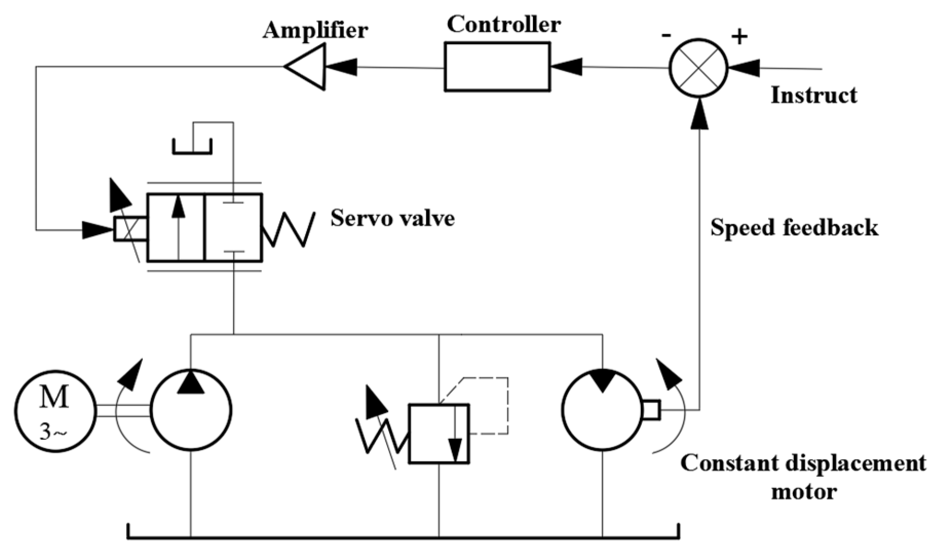
Figure 6.
Three-port pump-controlled asymmetric cylinder system.

Figure 7.
Variable displacement pump-controlled differential cylinder system.

Figure 8.
Asymmetric pump-controlled potential energy recovery system.

Figure 9.
Pump-controlled differential cylinder system compensated by hydraulic control check valve of loader.
Figure 9.
Pump-controlled differential cylinder system compensated by hydraulic control check valve of loader.

Figure 10.
The three-port pump directly controls the differential cylinder system.


Table 1.
Comparison between valve control system and pump control system.
| Valve Control System | Pump Control System | |
|---|---|---|
| Main Control Components | Proportional Valve, Servo Valve | Variable Displacement Pump |
| Characteristic | 1. The system must have an air circulation circuit to prevent equipment overload; 2. When the system is idling, there must be an unloading circuit; 3. When the system is overloaded, excess hydraulic oil will flow back to the oil tank through the safety valve or overflow valve, consuming a large amount of energy and causing the system to heat up; 4. In the valve control system, there is internal leakage loss of the valve and resistance loss caused by hydraulic oil passing through the valve. The more valves are used, the greater the leakage and resistance loss. | 1. When the equipment is started, the variable displacement pump is in the zero-flow position, so there is no unloading circuit, and the system will not overload during startup; 2. When the equipment is in standby, the pump can return to the zero-flow position, thereby reducing the no-load energy loss of the system; 3. When the system pressure reaches the set value, excess hydraulic oil does not overflow from the overflow valve, and the system safety protection is achieved by reducing the pump flow output; 4. When the system needs to accelerate or decelerate, it can be achieved by increasing or decreasing the pump flow output to achieve speed regulation, without the need for throttle valve speed regulation; 5. The pump control system reduces valve leakage and resistance loss due to the reduction in the control valves. |
| Advantage | Good dynamic characteristics, low cost, excellent control precision, quick reaction time, and simplicity of use | The system has high efficiency, low heat generation, low energy loss, relatively simple control principle, low noise, easy maintenance, and convenient installation |
| Disadvantage | Low system efficiency, high system heat generation, and complex control principles | Poor dynamic characteristics, low control accuracy, and high cost |
Table 2.
Summary of factors affecting power loss and energy-saving measures.
| Energy Conversion Loss | Energy Transmission Loss | Energy-Matching Loss | Energy Loss Caused by External Shocks | |
|---|---|---|---|---|
| Reason | The loss of energy conversion components in hydraulic control systems during energy conversion | The energy loss generated by the transmission of hydraulic working medium throughout the entire hydraulic system | The energy loss caused by the mismatch between the energy provided by the power source and the energy required by the load | The impact pressure may reach 3–4 times the normal working pressure, causing damage to components, pipelines, instruments, etc. in the system |
| Classification | Mechanical friction loss, pressure loss, and volume loss | flow loss | Local pressure loss and frictional pressure loss | |
| Measure | By improving component quality and developing new energy-saving components | Reduce the friction torque of the output shaft of the prime mover and improve the power-matching relationship between the two | By designing the structure of hydraulic components reasonably, the usage of bent pipe joints is reduced; make the structural design of the entire hydraulic control system as compact as possible | Add a more suitable coupling between the active and driven shafts of the equipment; reduce interference from proportional valves |
Disclaimer/Publisher’s Note: The statements, opinions and data contained in all publications are solely those of the individual author(s) and contributor(s) and not of MDPI and/or the editor(s). MDPI and/or the editor(s) disclaim responsibility for any injury to people or property resulting from any ideas, methods, instructions or products referred to in the content. |
© 2023 by the authors. Licensee MDPI, Basel, Switzerland. This article is an open access article distributed under the terms and conditions of the Creative Commons Attribution (CC BY) license (https://creativecommons.org/licenses/by/4.0/).
Share and Cite
MDPI and ACS Style
Li, R.; Zhang, Y.; Feng, Z.; Xu, J.; Wu, X.; Liu, M.; Xia, Y.; Sun, Q.; Yuan, W. Review of the Progress of Energy Saving of Hydraulic Control Systems. Processes 2023, 11, 3304. https://doi.org/10.3390/pr11123304
AMA Style
Li R, Zhang Y, Feng Z, Xu J, Wu X, Liu M, Xia Y, Sun Q, Yuan W. Review of the Progress of Energy Saving of Hydraulic Control Systems. Processes. 2023; 11(12):3304. https://doi.org/10.3390/pr11123304
Chicago/Turabian StyleLi, Ruichuan, Yisheng Zhang, Zhen Feng, Jikang Xu, Xiaowei Wu, Mengnan Liu, Yuhai Xia, Qiyou Sun, and Wentao Yuan. 2023. "Review of the Progress of Energy Saving of Hydraulic Control Systems" Processes 11, no. 12: 3304. https://doi.org/10.3390/pr11123304
Note that from the first issue of 2016, this journal uses article numbers instead of page numbers. See further details here.