
Hollow Fiber Membrane Modification by Interfacial Polymerization for Organic Solvent Nanofiltration


1
Oil & Gas Treatment Division, Research & Development Center, Saudi Aramco, Dhahran 34472, Saudi Arabia
2
Ordine Regionale dei Chimici e Fisici della Campania, 80138 Naples, Italy
*
Authors to whom correspondence should be addressed.
Processes 2024, 12(3), 563; https://doi.org/10.3390/pr12030563
Submission received: 14 February 2024
/
Revised: 7 March 2024
/
Accepted: 8 March 2024
/
Published: 13 March 2024
(This article belongs to the Special Issue Recent Advances in Processing Technologies for Substance Extraction, Separation, and Enrichment)
Abstract
:Hollow fiber (HF) organic solvent nanofiltration (OSN) membranes have recently attracted significant interest in the field of membrane technology. Their popularity stems from comparative advantages, such as high packing density, fouling resistance, and easier scalability for larger applications, unlike flat-sheet/spiral-wound OSN membranes, which may present challenges in these aspects. The combination of interfacial polymerization (IP) and HF configuration has opened up new opportunities for developing advanced membranes with enhanced separation performance that can be tailored for various OSN applications. The objective of this review is to discuss the latest advancements in developing thin film composite (TFC) HF membranes, with a focus on the IP method. Novel materials and processes are discussed in detail, emphasizing the fabrication of greener, interfacially polymerized HF OSN membranes. In addition, the commercial viability and limitations of TFC HF membranes are highlighted, providing perspectives on future research directions.
1. Introduction: Setting the Scene
Organic solvents are critical components in a wide range of industries, such as agriculture, pharmaceuticals, oil, petrochemicals, electronics, cosmetics, and food and beverage production [1]. They are predominantly used across all stages of a product’s lifecycle due to their ability to dissolve, extract, and facilitate chemical reactions. In these processes, solvents are often required for purification. Particularly in the pharmaceutical and fine chemicals industry, a significant volume of organic solvents is utilized, sometimes constituting as much as 90% of the total chemical consumption on a mass basis [2,3]. The extensive use of organic solvents underscores the necessity for efficient separation methods. However, the standard methods for chemical separations in the industry are distillation, evaporation, and liquid-liquid extraction. Notably, membrane-based processes, such as organic solvent nanofiltration (OSN), also known as organophilic nanofiltration (oNF) or solvent-resistant nanofiltration (SRNF), can save up to 90% of the energy consumed by chemical separations [3,4].
Membrane separation operations, such as reverse osmosis (RO), microfiltration (MF), ultrafiltration (UF) and nanofiltration (NF), electrodialysis (ED), dialysis (D), pervaporation (PV), gas separation (GS), membrane distillation (MD), electro-osmosis (EO), and forwarded osmosis (FO) (Table 1), are largely used in many different applications [5]. The OSN process, as a pressure-driven membrane process (Table 1), requires an external hydraulic pressure to make the separation among the components of the feed. Depending on the operating pressure, two different types of processes can be distinguished, i.e., OSN, which uses relatively low pressures (<30 bar) for the separation of solutes with molecular weights in the range of 150–1000 g mol−1, and organic solvent reverse osmosis (OSRO), where the required operating pressure to separate solutes with molecular weights <150 gmol−1 is higher than 30 bar [6,7]. Moreover, organic solvent forward osmosis (OSFO) (Table 1) has been demonstrated recently [8] as a promising technology for solvent recovery, as it possesses a reasonable solvent flux, low reverse solute flux, and requires no external pressure. Indeed, the solvent, due to its chemical potential gradient between the two membrane sides, spontaneously flows from the feed solution to the draw solution, thus concentrating the feed solution.
The OSN process consumes less energy, by an order of magnitude, compared to the traditional thermal separations, owing to its operation at lower temperatures [9,10]; hence, there is no need for phase change, such as vaporization and/or condensation steps, to perform the separation [11]. Additionally, OSN membranes provide more selective separation, being particularly beneficial for complex mixtures and facilities with space constraints due to their smaller footprint, along with preserving the quality of heat-sensitive molecules.
There are primarily three configurations for OSN membranes: flat-sheet (FS), hollow fiber (HF), and tubular configurations, as shown in Figure 1 [12]. FS configuration is the simplest form of an OSN membrane, often used in lab-scale experiments and small-scale applications [13]. The popularity of FS OSN membranes in academia can be attributed to being simpler to fabricate, handle, and characterize in lab settings compared to the other configurations. Flat sheets of membrane material can be stacked/layered in a plate-and-frame module or wound around a central tube, resembling a spiral-wound (SW) module, to maximize the filtration area. On the other hand, a hollow fiber (HF) configuration consists of thin, hollow strands of membrane material with an internal diameter typically less than 1 mm [14]. A similar configuration is a tubular configuration, which is larger in diameter compared to the HF configuration (i.e., internal diameter > 1 mm) [15]. They are often used in microfiltration (MF) and ultrafiltration (UF) applications, but have also been used recently to develop ceramic membranes with MoS2 selective layers [16] and polymeric selective layers [17] for OSN applications. While FS OSN membranes are more reported in the literature, there has been recently a substantial research interest in HF OSN membranes due to their self-supporting structure and high surface area-to-volume ratio, enabling dense packaging in a single module and allowing ease of scalability and separation efficiency in processing large volumes of solvent [18,19].
HF OSN membranes can be classified based on their structure/morphology into integrally skinned asymmetric (ISA) and composite membranes. ISA OSN membranes are typically fabricated using phase inversion and crosslinking methods to be stable in a range of organic solvents. They are characterized by a monolithic structure, consisting of a dense top layer (selective layer) and a porous sublayer (support layer), which are made from the same material. ISA OSN membranes are widely studied in academia and commercialized in SW module configuration from, e.g., Evonik (Essen, Germany), GMT Membrantechnik (Rheinfelden, Germany) (the parent company is Borsig GmbH, Berlin, Germany) and SolSep BV (Apeldoorn, The Netherlands). However, crosslinking the ISA HF membranes, to enable adequate chemical stability and molecular sieving in the nanoscale range, increases the solvent transport resistance through its thick structure and reduces the flux/permeance. On the other hand, composite OSN membranes can be prepared by coextrusion, dip coating, spray coating, grafting, introducing nanomaterials and interfacial polymerization. Even though in co-extrusion processes, a coating layer forms in situ onto a support membrane in a one-step process, its major challenge concerns the delamination of the two layers because the dope solution undergoes phase separation at both the inner and outer surfaces. Instead, the IP process allows the preparation of thin film composites (TFCs) with independently optimized layered structures, although commonly resulting in better adhesion between the support and the top layer. A thin selective layer is made of one material at the interface between two immiscible liquids, supported by a porous layer made of another material (relatively cost-effective), for mechanical support. Because of this, IP is a major breakthrough compared to the above mentioned processes.
Numerous review articles have been published on the latest material developments, fabrication methods and post-treatment methods, with a focus on FS OSN membranes [13,20,21,22,23] and their industrial applications [24,25]. Additionally, there are extensive reviews covering HF NF membranes for aqueous solutions and gas separation, which also briefly explore OSN as a potential application [14,26,27]. Fewer review articles have been published on HF OSN membranes in comparison, which mainly discuss in detail crosslinking and its methods [10], as well as polybenzimidazole (PBI) HF membranes [19]. One cannot find a recent review specifically addressing HF OSN membranes, including their material development, fabrication, and treatment methods [12]. This review aims to highlight the current research advancements in the fabrication of TFC HF membranes, with a focus on interfacial polymerization and the use of bio-based materials. It also aims to discuss the challenges encountered in OSN technology, its commercial viability, and future perspectives.
2. Separation Performance of HF OSN Membranes
2.1. Separation Mechanism: The Swelling Challenge
While both OSN and NF membranes for aqueous solutions share the fundamental principle of size-exclusion separation, the specifics of their separation mechanisms differ significantly, due to the distinct properties of organic solvents and aqueous solutions [28]. The pore size of OSN membranes is typically tailored to the size and shape of the solutes, as the size exclusion is the dominant separation factor [11]. However, the separation mechanism can involve a combination of size exclusion, solubility-diffusion, and possibly adsorptive and electrostatic interactions between charged solutes and the membrane selective layer. The solvent/membrane interactions are more pronounced in the separation performance of polymeric OSN membranes than the solute/solvent interactions [23]. The solubility and swelling behavior of polymers in solvents are often predicted using the Hildebrandt and Hansen solubility parameters [29,30]. In general, membranes are less chemically stable in solvents with solubility parameters similar to the polymer, leading to solvation and possible swelling or dissolution. Conversely, membranes show better chemical stability in non-solvents, which have dissimilar solubility parameters and interact less with the polymer. Indeed, OSN membranes often suffer severe swelling and solvation when being exposed to harsh organic solvents, which cause alterations of membrane characteristics and filtration performance [31,32,33]. Ebert and Cuperus [34] reported that polymeric chains in dense polymeric membranes move further apart during swelling, thus increasing the free volume; the membrane becomes more open (Figure 2a). On the other hand, when a porous membrane swells, the pores become narrower. The membrane becomes less open, which results in higher rejections and the deterioration of flux.
However, it is important to emphasize that swelling can work in different manners, influencing membrane performance differently, depending on factors such as solvent/membrane interactions, the pressure applied, and the crosslinking of the membrane material. These issues are well described by Tarleton et al. [35], who tested cellulose fiber/PAN/PDMS composite membranes (Figure 3).
Tarleton et al. [35] assessed the swelling of four membranes, as reported in Figure 3, across the pressure range of 0–2000 kPa (Figure 4). All of the tested membranes showed a reduction in swelling with increased pressure. This reduction, attributed to membrane compaction, reduces the phenomenon, even though in different ways, dependent upon factors such as the starting thickness of PDMS and the degree of crosslinking.
For membrane materials that are different from rubbery polymers such as PDMS, but are instead based on glassy polymers with high glass transition temperatures, such as polybenzimidazole (PBI) and polyimides (PI), which have high strength, the challenge is their brittleness when being fabricated into self-support hollow fiber membranes [36,37]. The mechanical strength of hollow fiber membranes under high pressure operations has been increased by various cross-linking modifications and fabrication approaches [38,39,40,41,42,43,44]. Among cross-linking modifications, one by Chen et al. [44] is worthy of mention, being a green approach: it doesn’t use toxic organic solvents such as hexane, but rather a potassium persulphate (K2S2O8) water solution at room temperature, as discussed below, in Section 4.5, “Alternative fabrication methods”. The approach was successfully employed to modify PBI hollow fibers with superior separation performance for OSN applications [45]. Regarding fabrication approaches, braid-reinforced hollow fibers offer a solution to increase mechanical strength and extend the useful lifetime of hollow fiber membranes [46,47]. Zhao et al. [48] reported braid-reinforced PBI hollow fibers (Figure 5) as solvent-resistant membranes for OSN applications with the aid of the aforementioned green cross-linking method based on the (K2S2O8) water solution [10,44].
2.2. Performance Characterization
The performance of OSN membranes (or OSN process) can be evaluated in terms of productivity and separation efficiency. Productivity indicates how fast the separation can be achieved and expressed as flux or permeance. The permeance can be calculated using Equation (1), in which the permeate volume (V) is divided by the membrane effective area (A), time (t), and the transmembrane pressure (ΔP). Separation efficiency indicates how well separation can be achieved and is commonly denoted as the rejection or removal efficiency as percentage of the solutes rejected by the membrane. Rejection can be calculated using Equation (2) based on permeate concentration (Cp) and feed concentration (Cf).
The molecular weight cut-off (MWCO) is defined as the molecular weight of a solute to be rejected at least 90% by the membrane, as shown in Figure 6a, which is often used as a metric to estimate the molecular sieving property of the HF membrane. Various types of dyes, food additives and APIs with different molecular weights (e.g., 100–1000 g mol−1) are used as “markers” or “solutes” to determine the MWCO of HF OSN membranes. However, the types of solutes and solvents used for performance screening in the OSN membrane literature are not standardized. However, it is recommended that solutes with similar physicochemical properties and different molecular sizes be used to determine the MWCO, such as a homologous series of alkenes, polystyrene oligomers, and poly(propylene glycols) (PPGs) [28,49]. Moreover, regarding solvent selection, it is recommended to test at least one solvent from each class, such as apolar solvents (hexane, heptane, toluene), polar protic solvents (isopropanol, methanol, ethanol), mild polar aprotic solvents (acetone, acetonitrile, ethyl acetate), and harsh polar aprotic solvents (DMSO: dimethyl sulfoxide, DMF: N,N-dimethylformamide, THF: tetrahydrofuran) [28]. However, alkenes have limited solubility in polar solvents, especially those with higher molecular weights [50]. PPGs are also utilized but pose detection challenges, and they are not as well established in the literature compared to other markers [51]. On the contrary, polystyrene oligomers are commonly used due to their solubility in many organic solvents and commercial availability, although lower molecular weight variants can be expensive [52].
For the OSN process, there are mainly two process configurations (dead-end and cross-flow configurations) to test the separation performance of the HF OSN membranes. The cross-flow configuration is more relevant industrially and the most reported in academia [53], as depicted in Figure 6b, since it minimizes concentration polarization on the membrane surface, allowing continuous operation and steady-state conditions to be reached.
![Processes 12 00563 g006]()
Figure 6.
(a) Simulated MWCO curves of different membrane (dash lines) are compared to the desired sharp MWCO curve of 100% rejection (solid line). Reprinted with permission from Ref. [11]. Copyright 2014, American Chemical Society. (b) Schematic illustration of laboratory scale cross-flow filtration set-up. Reproduced under CCBY 4.0 from Ref. [54].

3. Fabrication of Interfacially Polymerized HF OSN Membranes
3.1. Interfacial Polymerization Fundamentals
The IP process begins with the fabrication of the porous support, which will provide the mechanical stability of the TFC membrane, followed by the dispersion of two immiscible monomer phases, often referred to as the aqueous and organic phases. These monomers possess complementary reactive groups that can undergo a rapid and selective reaction when brought into contact at the interface, as shown in Figure 7. One of the significant advantages of IP is its ability to independently optimize the support layer to be mechanically robust and highly permeable, along with tailoring the selectivity and thickness of the top layer. The selective layer can be optimized by adjusting the reaction conditions, such as concentration and type of monomers, reaction time, and temperature, and by modifying the support layer. Common reactive groups of monomers include amines, phenols, and acid chlorides. A comprehensive review of the IP method and advancements in monomers is conducted by Li et al. [23].
The IP process for fabricating the TFC HF membrane is described in Figure 8. First, the HF support is stored in a water bath (Bath 1). The porous support then contacts the 1st solution, which contains reactive monomer 1. Depending on the contacting time and the viscosity and surface tension of the solution, the penetration depth of the solution into the porous support can vary. It needs to be controlled well to manage the thickness of the selective layer. The saturation degree can be controlled by increasing or decreasing the immersion time of the support in the reactive solution 1. More specifically, the immersion time is controlled by adjusting the motor speed M1 and the number of loops in Bath 2. Depending on the speed of M1, the tension controller (R1) controls the motor speed of the support bobbin (M2). Removing the excess reactive solution from the membrane surface is one of the most challenging steps, and it can be achieved by an air blower (AB). At a fixed coating speed, adjusting the air flow rate and pressure can completely remove any excess. The saturated porous support with solution 1 then comes into contact with the 2nd solution, which contains reactive monomer 2. Then, the reaction between monomers 1 and 2 occurs at the pores’ openings, starting to form the selective layer. Herein, the reaction rate of the monomers is controlled by kinetics and then slowed down by diffusion [55]. The selective layer could hinder reactive monomer diffusion and inhibit further growth, namely the self-sealing process [56]. The resultant fibers pass through this drying tower (DT), where the solvent is dried, and the selective layer is thermally crosslinked. The drying tower consists of several heating guns and temperature sensors to monitor and control the drying temperature. Besides the heating gun, infrared (IR) and/or ultraviolet (UV) light can be employed. The tower length and the temperature profile can determine the drying speed. Finally, the TFC HF membrane is collected on the bobbin in Bath 4. The collecting speed is controlled by a second tension controller (R2) and bobbin-connected motor (M3).
3.2. Porous Support
To develop the optimal structure for an interfacial polymerized OSN HF membrane, the design should include a porous support that is both solvent-resistant and mechanically robust, capable of withstanding high pressures while maintaining high permeance. Additionally, it should feature a selective layer with nanofiltration-sized pores to ensure efficient solute rejection. This can be achieved by initially fabricating a UF membrane to act as the support layer, and subsequently applying a thin polyamide selective layer. The optimum porous support (including both ISA and composite morphologies) should have the following features, as mentioned by Chung’s group: (i) a no-defect and uniform top layer, (ii) optimized pore size with a narrow distribution, (iii) minimum filtration resistance (i.e., high solvent permeance), and (iv) adequate mechanical stability under high pressures [57]. Additionally, the porous support must be chemically stable in harsh organic solvents, and this is usually achieved by integrally crosslinking the membrane matrix (refer to Section 3.4.1 for a discussion on this matter).
Polymeric membranes, such as polyimide (PI) [57,58,59,60,61], polyacrylonitrile (PAN) [62], polyvinylidene fluoride (PVDF) [63], polypropylene (PP) [32], and polytetrafluoroethylene (PTFE) [64] are widely used to fabricate the porous support due to their cost-effectiveness and ease of synthesis. Phase inversion/separation is still the most common method to fabricate these polymers onto HF porous support. Phase inversion is simply described as a process where a solvent–polymer solution, often referred to as a dope solution, solidifies from a liquid phase to a solid phase. This phase transformation can be achieved by various techniques, including thermally induced phase separation (TIPS), non-solvent induced phase separation (NIPS), adsorption of non-solvent vapor (VIPS), and evaporation-induced phase separation (SIPS) [65]. NIPS is the most reported technique for the fabrication of ISA HF porous support via liquid-liquid demixing, usually using water and mild or harsh polar aprotic solvents. The fabrication process can be explained thermodynamically by the ternary phase system (i.e., a polymer–solvent–non-solvent system) [66]. The final morphology of the HF membrane can be controlled by several parameters, such as the concentration of dope solution and bore fluid, dope flow rate, take-up speed, air gap, temperature (i.e., temperature of coagulation bath and spinneret), and type of spinneret (double or triple spinneret). Single-layer HF membranes (one type of polymer) can be fabricated using a double spinneret, whereas double-layer HF membranes (two different polymers) can be fabricated using a triple spinneret, as shown in Figure 9a,b respectively.
A single-layer HF membrane via NIPS is the preferred option due to its simplicity. However, optimizing the fabrication parameters (e.g., pore-forming additives, concentration, and viscosity of the dope solution, etc.) to control the ISA structure is challenging. Delaying the demixing leads to a tighter structure (low permeance), while instantaneous demixing leads to a higher number of macrovoids (high permeance) with a broader pore size distribution (unfavorable for depositing the selective layer via IP). Additionally, high mechanical strength is critical for the TFC HF membrane to operate under high pressures, which is challenging for the HF support layer with the ISA morphology. These parameters, which are related to the shear force/stress exerted in the spinneret, such as air gap length and take-up speed, were extensively investigated by Chung’s group [67,68,69] and highlighted by Wang et al. in a recent publication [70]. One way to improve mechanical strength involves braiding the fibers, similar to the concept of non-woven support, which is usually used in FS configurations [71,72]. Zhao et al. [48] as mentioned above, developed a braided PBI HF membrane with high mechanical strength (i.e., withstanding more than 10 bar), lower swelling ratio, and improved separation performance compared to the self-support PBI HF membrane in organic solvents (methanol performance of 3.6 L m−2 h−1 bar−1 and 90% rejection of rose Bengal, RB).
Dual layer HF membranes incorporate a similar benefit to those of TFC HF membranes. This involves utilizing a more economical polymer for the support layer to provide mechanical strength while using less of the more costly polymer for the selective layer. It is worth highlighting that dual layer HF membrane can also be referred to, in the literature, as the coextrusion of one polymer type using a triple spinneret with different fabrication parameters/conditions. This can solve one of the main limitations of dual layer HF membranes, which is the poor adhesion/delamination between two polymers or layers [73,74]. Sun et al. [57] fabricated a dual layer PI HF support utilizing less non-solvent to slow down the coagulation of the outer surface layer while the inner surface layer undergoes fast coagulation (i.e., forming highly porous morphology), followed by chemical crosslinking with 1,6-Hexanediamine (HDA) to enhance the chemical resistance of the membrane. Specifically, the addition of polyvinylpyrrolidone (PVP) to the outer dope solution was investigated for its ability to slow precipitation and, consequently, achieve a narrower pore size distribution suitable for the IP of the polyamide selective layer (methanol permeance of 0.9 L m−2 h−1 bar−1 and 99.3% rejection of Remazol brilliant blue, RBB) [57]. Similarly, HF OSN membranes can be fabricated in one step, combining precipitation and crosslinking steps simultaneously. This method, referred to as ‘‘Chemistry in a spinneret’’, follows the work of Kopeć et al. [75] and Dutczak et al. [76], aiming to optimize the fabrication steps of a crosslinked polyimide support (i.e., polyethylenimine (PEI) was used as a crosslinking agent). A novel crosslinked HF polyelectrolyte membrane was developed via combining ionic crosslinking between PEI and polystyrene sulfonate (PSS), covalent crosslinking using glutaraldehyde (GA), and phase inversion in the spinneret, as depicted in Figure 9c [77]. Additionally, Sun et al. [78] applied the same concept by combining crosslinking with phase inversion using a PBI dope solution as the outer surface layer (selective layer) and feeding a polyimide dope solution to the inner surface, due to its imide groups, to be further crosslinked with PEI. The optimal membranes showed more than 99% rejection toward methylene blue (MB) in methanol and acetonitrile [78].
Another limitation of the ISA porous support is structural relaxation, often associated with physical aging, which occurs as the polymer system moves towards thermodynamic equilibrium. When polymers are processed or used at temperatures that are different from their production temperature, their molecular chains may not be in equilibrium. Over time, these chains rearrange to minimize the system’s free energy, leading to changes in various physical properties of the polymer, such as density, free volume, and mechanical properties. On the other hand, membrane compaction refers to a phenomenon where the physical structure of a membrane undergoes densification, often because of prolonged exposure to pressure, temperature, and harsh chemical environments. In the long run, pressure can cause the polymer chains in the membrane to pack more closely together, reducing the membrane’s adequate pore size and porosity and, hence, leading to a gradual loss of permeance. Physical aging and compaction challenges are more pronounced in ISA membranes, where larger pores and macrovoids are present, compared to TFC membranes [79]. Incorporating TiO2 nanoparticles into the crosslinked polyimide matrix (mixed matrix HF membranes, MMMs) has been demonstrated to enhance compaction resistance and the hydrophilicity of the resultant membranes by decreasing porosity (eliminating the macrovoids in the membrane sublayer) without affecting its separation performance (i.e., permeance and rejection of styrene oligomers in DMF) [79]. In addition, single-layer PI HF membranes compromising amine-functionalized multi-walled carbon nanotubes (NH2-MWCNTs) were fabricated using NIPS by Farahani and colleagues [80]. The MMMs, crosslinked with HDA for 15 h at room temperature, showed higher mechanical strength and separation performance of tetracycline, L-αlecithin, and BINAP-Ru(II) complexes compared to pristine polyimide HF membranes in polar solvents (e.g., acetone, methanol, isopropanol, and ethanol) [80].
Instead of using polymers as support membranes, ceramics have also been investigated as support layers, owing to several advantages, such as high thermal stability, chemical resistance, and superior mechanical strength for OSN [81]. A multi-layer ceramic UF membrane (in a tubular configuration), with intermediate layers, was successfully demonstrated as a support membrane to deposit a polyamide selective layer via IP [81]. Furthermore, ceramic HF membranes are often fabricated by spinning out precursors via the NIPS approach followed by sintering. In recent work, high-performing TFC HF membranes (MWCO of 340 g mol−1) were fabricated via direct IP of PEI/PIP selective layers on a ceramic HF membrane without an intermediate layer and found to be stable in aqueous solutions at high temperatures (i.e., 80 °C) [82]. Further, a hybrid of PAN and silicon nitride (Si3N4) ceramic HF membranes have been successfully applied as support layers in the IP fabrication of polyamide selective layers [62]. However, ceramic HF membranes are cost-prohibitive, fragile, and nonflexible regarding pore size and surface properties [23].
Other methods include grafting treatment; although it can be directly used in the spinning step, its utilization in modifying the HF support layer is rarely reported. This method includes applying UV/photo irradiation, e-beam, and plasm on the outside layer of the membrane, allowing the tuning of its properties, such as hydrophilicity and surface charge [83,84]. Notably, plasma grafting has been demonstrated to enhance the mechanical and chemical stability of the membrane (i.e., PDMS membrane) in isopropanol, methanol, and diethyl ether. These enhancements are ideal for modifying the UF membrane as a support layer [85]. However, the main drawback of these methods is their limitation to the outside-in geometry only, limiting the available options to be applied for modifying the support layer for IP fabrication.
3.3. Selective Layer
In aqueous solution applications, the state-of-the-art selective layer of TFC HF membranes (NF and RO) is a polyamide layer formed by the IP reaction between diamine and diacyl chloride [86]. It has also been adapted to fabricate TFC HF membranes for OSN applications. The IP reaction typically takes place on the inner surface (lumen side) of the HF support, as shown in Figure 10a, and it can also be performed on the outside surface (shell side), depending on the specific application. The latter type allows for the outside-in operation mode, which is generally more commercially applicable due to the larger effective membrane area and reduced pressure drop.
It is worth mentioning that the work of Kosaraju and colleagues was among the first to pioneer the fabrication of TFC HF membranes specifically for OSN [32,86]. In their work, pre-wetted PP microporous support, with acetone, was oxidized using a chromic acid solution to have better adhesion with the selective layer. Following this, a solution containing PEI and isophthaloyl dichloride (IPD) was interfacially polymerized into the inner side of the PP fibers [32]. The resulting membranes were thermally treated, and the SEM of the membrane cross-section with a thickness of ~100 nm is shown in Figure 10b. They demonstrated a methanol permeance of 1.47 L m−2 h−1 bar−1 but exhibited a low rejection of 88% for brilliant blue R (BBR) [32]. To improve rejection and solvent permeance, a less dense polyamide layer with reduced crosslinking can be created, using the branched PEI as the aqueous phase monomer [32]. This has been shown to increase solvent permeance (e.g., acetone permeance of 11.6 L m−2 h−1 bar−1) [58]. In addition, incorporating a small quantity of piperazine (PIP) can enhance crosslinking density, improving solute rejection (i.e., 91.8% rejection of acid fuchsin) without significantly affecting solvent permeance [58]. However, the developed TFC HF membranes were unstable in harsh polar aprotic solvents such as DMF. In addition, the IP reaction between m-phenylenediamine (MPD) and trimesoyl chloride (TMC) has a high degree of crosslinking and results in a very selective layer suitable for separation in organic solvents. Nevertheless, it typically results in low solvent permeance [57]. On this basis, Goh et al. developed a defects-free MPD–TMC layer on crosslinked PI support for the concentration of APIs [59]. The optimal membrane, achieved by applying solvent activation with DMF as the post-treatment step as discussed below has a low MWCO of 269 g mol−1 and high acetone permeance of 24.2 L m−2 h−1 bar−1. They also demonstrated the scalability of the fabrication method of the HF module from a 5-piece module to a 100-piece module with an active membrane area of 724 cm2. Despite these promising results, controlling the thickness of the polyamide layer by IP is a significant challenge for scale-up fabrication. In particular, interfacial reactions occur at the boundary between the aqueous and organic phases; the reaction occurs rapidly, releasing a substantial amount of heat that can cause local increases in temperature. In this context, the locally heated areas facing the hexane layer become less dense and rise, while the cooler, denser areas sink. This creates a convective cell pattern (Rayleigh–Bénard convection) driven by buoyancy [87]. An innovative approach is to utilize a sacrificial support or intermediate layer to overlay the thin selective layer. Using the sacrificial layer approach allows precise control over the thickness of the selective layer and minimizes its defects, such as forming pinholes or cracks. The final step involves removing the sacrificial nanostrand layer. This is typically done using a solvent or etching process that dissolves or lifts away the nanostrands without damaging the thin selective layer. Karan et al. [88] fabricated an ultrathin polyamide layer with less than 10 nm thickness on cadmium hydroxide nanostrands (sacrificial layer), deposited on a crosslinked PI or alumina support. However, this technique of fabricating the ultrathin polyamide layer may face challenges in scaling up, particularly for HF support membranes. Interestingly, polymers of intrinsic microporosity (PIMs) have garnered interest due to their high free volume, porosity, and pore tunability. They are used for developing the selective layer for TFC membranes in OSN applications, mostly applied by coating methods such as dip coating and spray coating [89].
PIM-1 have been successfully fabricated in FS configuration by dip coating on a PAN support [90], followed by solvent vapor annealing (SVA) to control solvent evaporation [89]. Notably, Park et al. [91] fabricated HF TFC membranes via dip coating onto a crosslinked PI, followed by intermolecular crosslinking. The resultant membranes exhibited a MWCO of 952 g mol−1 and a high ethanol permeance of 10.9 L m−2 h−1 bar−1. Although solvent permeance and selective layer thickness have an inverse correlation, decreasing the thickness of the selective layer does not always translate to high solvent permeance [92]. Livingston’s group demonstrated that reducing the thickness of a selective layer containing linear polymers (<140 nm) resulted in reduced permeance, which was attributed to their structural relaxation toward the equilibrium state [93]. In contrast, network polymers such as the highly crosslinked MPD–TMC polyamide can be fabricated successfully with a thickness of less than 100 nm.
Various fabrication techniques are employed to enhance the TFC HF membranes, such as incorporating additional nanomaterials into the selective layer, referred to as thin film nanocomposite (TFN) [93]. While these methods effectively modify membrane characteristics, such as permeance and chemical resistance, the compatibility of swelling properties across different layers is crucial for preventing delamination. Su et al. [60] developed a TFN HF membrane by incorporating graphene oxide (GO) nanosheets into the selective layer of TFC HF membrane, which is fabricated via IP of MPD and triethanolamine (TEA) with the addition of surfactants such as sodium dodecyl sulfate (SDS) to uniformly depositing the MPD aqueous solution on the HF support. The addition of GO improved ethanol permeance by approx. 66% while maintaining solute rejection. Further, Nunes’ group reported spray coating for depositing a thin layer of GO on a crosslinked polyetherimide HF membrane (i.e., HDA was used as the crosslinker) via an airbrush, resulting in a MWCO of 973 g mol−1 and acetone permeance of 4 L m−2 h−1 bar−1 [94]. Recently, covalent organic frameworks (COFs) have gained significant attention for their potential use in membrane technology. COFs comprise hydrogen, boron, carbon, nitrogen, and oxygen, linked by strong covalent bonds. This structure endows COFs with several unique properties for OSN, such as high surface area, thermal stability, and well-defined pores (1–5 nm channels) [95,96]. Gao et al. [61] reported that COFs could be uniformly disturbed on the inner surface of crosslinked PI HF support, using a tris(4-aminophenyl)amine (TAPA) aqueous solution on the shell side and a benzene-1,3,5-tricarboxaldehyde (BTCA) organic solution on the lumen side to react at the interface and grow the COFs. The resultant membranes showed Janus-like properties (i.e., having hydrophilic pores to allow polar solvents to pass through the crosslinked PI support and having hydrophobic cavities of imine-linked COFs for non-polar solvent transport), leading to a high isopropanol permeance of ~62 L m−2 h−1 bar−1 (MWCO~784 g mol−1). The separation performance of these membranes is the best reported yet compared to other HF OSN membranes (including TFC and TFN HF membranes). However, a primary limitation of incorporating nanomaterials is the poor adhesion and aggregation of the discrete additives within the polymer matrix. Such issues can lead to the development of non-selective voids, ultimately diminishing the membrane’s separation efficiency and overall performance, leading to high cost and the possibility of leaching from the membrane during operation [97].
3.4. Post-Treatment Methods
3.4.1. Crosslinking
Crosslinking is a post-treatment method, after HF spinning, commonly employed to enhance the rigidity of porous support membranes (e.g., PI, PAN, polyetherimide, etc.), thereby reducing swelling and improving their resistance to organic solvents, especially against strong polar aprotic solvents such as DMF (Figure 11). Crosslinking involves creating bonds between polymer chains, which can be either covalent or ionic. However, most research and applications in OSN predominantly utilize covalent crosslinking, which includes chemical, thermal, or photo-induced processes. Among them, chemical crosslinking has become the go-to option for modifying the porous support for OSN. This method has also effectively reduced the pore size, enhanced the mechanical strength, and improved the molecular sieving properties of HF OSN membranes.
Diamines (e.g., aliphatic, aromatic, and polymeric diamines) are widely used as crosslinking agents owing to their compatibility and reactive nature with PI and polyamide-imide (PAI) [98]. The existence of amine groups can interact with the imide groups of PI, leading to the opening of the rings and the formation of an integrated structure with improved chemical stability in the most common polar aprotic solvents, such as dichloromethane (DCM), N-methyl-pyrrolidone (NMP), THF, and DMF [99,100]. Lim et al. [101] developed PAI HF membranes for low-pressure OSN applications (i.e., the operating pressure is under 2 bar) using 3-aminopropyl trimethoxysilane (APTMS) as a crosslinking agent. The best-performing membranes achieved an RB rejection of over 97% and permeance of 0.9 L m−2 h−1 bar−1 and 6.4 L m−2 h−1 bar−1 for isopropanol and DMF, respectively [101]. Furthermore, Tham et al. [102] fabricated OSN HF membranes by chemical crosslinking a PAN UF membrane with cost-effective hydrazine monohydrate at 70 °C. Crosslinking time, dope solution composition, dope and bore fluid flow rate, and take-up speed were adjusted to minimize the macrovoids in the ISA membrane’s spongy structure, achieving nanofiltration performance in ethanol without the need for coating or interfacial polymerization (with a permeance of 2.32 L m−2 h−1 bar−1 and 99.9% rejection of Remazol brilliant blue R) [102]. On the other hand, diisocyanates (i.e., 1,6-Hexamethylene Diisocyanate, HMDI) are also reported to crosslink the polyamide layer and PI support layer, achieving a low MWCO of 260 g mol−1 [103]. However, the permeance was very low at 1.2 L m−2 h−1 bar−1 and 0.1 L m−2 h−1 bar−1 for acetone and NMP, respectively (the membrane swelled in NMP over time) [103].
Another approach to achieving high solute rejection was demonstrated by Wang et al. [104]. This method involved the dual modification of α,α′-dibromo-p-xylene (DBX), followed by impregnation with 4-sulfocalix [8]arene (SCA8), which was demonstrated to enhance the mechanical strength and molecular sieving properties of PBI HF membranes. The resultant membranes have a low MWCO of 217 g mol−1 but with a dramatically reduced acetone permeance of 0.35 L m−2 h−1 bar−1 [104]. Comprehensive reviews specialized in crosslinking PBI and PI have been published elsewhere [19,98]. Interestingly, Loh et al. [105] showed that adding large organic acids such as malic acid into polyaniline (PANi) before spinning and removing the acid after spinning can introduce molecular sieving in the nanofiltration range with a MWCO of ~350 g mol−1 at 20–30 bar in acetone (permeance of 1.5 L m−2 h−1 bar−1), making the acid doping and de-doping method suitable for fabricating OSN HF membranes in ISA morphology. Achieving the optimal crosslinking level is crucial, as over crosslinking can lead to a sharp drop in solvent permeance. In contrast, insufficient crosslinking may not provide the necessary enhancements in mechanical strength and solvent resistance. The key takeaway is that crosslinking is inevitable as an additional step in fabricating TFC HF membranes for OSN, as it is a prerequisite for improving the chemical resistance of the membrane’s porous support when exposed to various organic solvents.
3.4.2. Solvent Activation
Livingston’s research group has pioneered a promising approach that leverages a simple solvent treatment using strong polar aprotic solvents such as DMF to enhance membrane performance (it is also known as solvent activation or solvent annealing) [106,107]. The solvent activation technique showed applicability for OSN and aqueous solution separations, such as desalination, with benzyl alcohol acting as a solvent activator [108]. In addition, a range of common solvents, such as methanol, ethanol, isopropanol, and DMSO, have demonstrated efficacy in solvent activation, attributed to their ability to swell and induce structural deformation in the polyamide selective layer, coupled with a consequent alteration in its microstructural arrangement, thereby facilitating enhanced solvent permeance [107].
The extent of swelling depends on the type of selective/support layer, activation duration, and the solubility parameters of the solvents (i.e., solvency power). Studies have revealed that solvent-induced changes in the performance of polyamide-based TFC membranes can be predicted using Hansen solubility parameters [108,109]. For example, the crosslinked PI HF support membranes (reported by Wang’s group in the previous paragraph) were fabricated to be thinner to increase the packaging density of the fibers, and the spinning parameters were optimized to obtain a tighter selective layer. This enhanced the selectivity of the resultant TFC HF membranes and hence lowered the permeance. The MPD-based TFC membranes were activated with DMF to increase the acetone permeance by almost 5-fold to 24.3 L m−2 h−1 bar−1 while maintaining its solute rejection (MWCO of 269 g mol−1 in acetone). This can be attributed to the swelling of weaker molecular chains of the polyamide layer and the crosslinked PI support layer due to similar solubility parameters with DMF. The aliphatic part of the polyamide layer tends to stretch, enabling the entry of DMF into the membrane matrix, while the aromatic part of the crosslinked network prevents it from dissolving, as represented in Figure 12 [59,110]. Therefore, semi-aromatic polyamide structures containing aromatic rings and hexagonal structures showed minimal change with solvent activation [88,110].
Vankelecom and co-author [109] conducted a study on the effect of solvent activation on PI-based ISA membranes. They noted that solvent activation could lead to the reorganization and densification of polymer chains in the membrane rather than a looser structure [109]. They found that solvent activation with DMF transforms the crosslinked PI membrane from UF to OSN membrane with a MWCO of approx. 300–500 g mol−1 and higher ethanol permeance (up to 400%) compared to commercial Duramem membranes with similar MWCOs [109]. The high densification of the top selective layer is possibly due to the favorable interactions (e.g., π-π interactions and hydrogen bonding) between the flexible PI chains and the additional crosslinking of the PI matrix with the remaining crosslinking agent (i.e., crosslinking the unreacted PI chains with HDA). In this case, the densification depends on the degree of crosslinking, as a highly crosslinked PI will probably not be affected, and the duration of solvent activation.
3.4.3. Thermal Annealing
Thermal annealing (referred to as thermal crosslinking or thermal treatment) of TFC OSN membranes can significantly influence the properties of each layer, depending on the temperature and duration, by rearranging the polymer chains and adjusting the crosslinking density, which affects the membrane’s solvent resistance and separation characteristics. This technique can achieve the desired selectivity and permeance by reducing defects in the selective layer, leading to improved rejection of solutes [111]. The support layer of TFC membranes also benefits from thermal annealing by strengthening the mechanical integrity and chemical resistance. For example, thermal annealing is an effective method to crosslink a PANi HF membrane (i.e., at a temperature of 180 for 1 h °C) to make it stable in an organic solvent environment [105]. In addition, Lai et al. [112] deposited a polypyrrole (PPy) selective layer onto a poly(p-phenylene terephthamide) (PPTA) braided support via chemical vapor deposition (CVD), which involves applying a thermal annealing step with an oxidative initiator (FeCl3) to achieve the reaction. Furthermore, a thermal annealing step can be used to accelerate the crosslinking reaction (i.e., crosslinking a PAN membrane with hydrazine monohydrate at 70 °C) [102,113].
The advantages and disadvantages of the fabrication methods of HF OSN membranes discussed in this section are summarized in Table 2, including the IP fabrication method and the post-treatment methods.
Table 3 presents the separation performance of the HF OSN membranes reported in the literature. It is worth highlighting that the “screening” refers to the filtration durations of less than one day, which is different from the long-term static immersion test for characterizing the chemical resistance of the membranes. Long-term cross-flow filtration (>1 day) is highlighted herein as more industrially viable. Relative to ISA HF OSN membranes (single or double layer), TFC HF membranes exhibited superior solvent permeance and comparable rejection. The median permeance of TFC HF membranes is 5.8 L m−2 h−1 bar−1, 132% higher than the recommended solvent permeance of approx. 2.5 L m−2 h−1 bar−1 highlighted by Livingston’s group. However, the median molecular weight of the solute is approx. 627 g mol−1 (with an average of ~693 g mol−1), which is higher than the average molecular weight of APIs (i.e., 300 g mol−1) in the pharmaceutical industry [107,114]. Notably, among these composite membranes, those with the COF selective layer demonstrated remarkably high solvent permeance, surpassing others by an order of magnitude [61].
3.5. Module Configuration
An HF module generally consists of four parts: the membranes themselves, membrane housing, potting, and end caps, as schematized in Figure 13A. Commercial modules are commonly around 1.5 m length. Instead, in academia, modules of 10–30 cm length are typically used [122]. As emphasized in the context of other membrane processes [123], it is important to realize that research on small, lab-scale hollow fibers cannot be simply translated into the performance of full-scale membrane modules due to membrane length being an important factor in recovery and retention [123,124,125,126]. Another important issue in module design is the operation mode (Figure 13B). Most of the studies regarding HFs for OSN applications are focus on inside-out HFs, where the selective layer is formed via interfacial polymerization onto the interior layer of the fiber. However, there is the possibility of using outside-in HFs with the selective layer applied to the outer layer of the fiber.
4. Greener Interfacially Polymerized HF OSN Membranes
Despite the widespread application of OSN technology, most commercially available OSN membranes are currently manufactured from fossil-based polymers, such as polybenzimidazole, polysulfone, and polyamide using environmentally harmful solvents. Nanofiltration membranes fabricated from these conventional polymers undergo a linear lifecycle (Figure 14), necessitating disposal in a landfill or environmental setting (approximately 79% of polymers) or incineration (approximately 12% of polymers) at the end of their lifecycle, which in turn leads to substantial carbon dioxide emissions [121].
The overall research landscape in the domain of interfacially polymerized TFC HF membranes for OSN is particularly limited, especially in aspects concerning environmentally friendly, or ‘green’, fabrication methods. In this section, we will explore studies that focus on the green fabrication of TFC membranes, which are mainly in flat sheet configurations. The aim is to draw inspiration from these studies and explore how their environmentally conscious approaches can be adapted and applied to the fabrication of TFC membranes in HF configuration.
4.1. Greener Solvents
The fabrication of OSN membranes involves using hazardous polar aprotic solvents, such as NMP, DMAc, and DMF for the fabrication of the support layer, which is prepared by non-solvent-induced phase separation and apolar aprotic solvents such as n-hexane, used in the interfacial polymerization process. All of these solvents pose significant challenges in terms of handling and disposal. They are often released into the environment, causing severe harm to aquatic and terrestrial ecosystems. In particular, n-hexane, a fossil-derived solvent, is toxic to aquatic life and potentially damaging to fertility [127]. Green alternatives to these solvents would be those derived from renewable biomass sources, and they should not only be less toxic and safer to handle, thereby reducing health and safety risks, but also match or surpass the solubilization power of their fossil-based counterparts, contributing to the conservation of fossil energy resources while offering a lower ecological footprint. There has been a notable shift towards developing bio-based solvents in recent years. In a recent study, Lin et al. [128] proposed cyclopentyl methyl ether (CPME) and 2-methyltetrahydrofuran (2-MeTHF) as alternative solvents to n-hexane for interfacial polymerization. CPME is a fossil-fuel-derived solvent that can be potentially produced from bio-derived adipic acid and furfurals [129], and 2-MeTHF [130] could be synthesized from various biomasses. These solvents are promising alternatives to n-hexane for interfacial polymerization because they have low miscibility with water and can dissolve chemicals used in polyamide synthesis, such as TMC [129]. Lin et al. [128] produced sustainable TFC membranes with better performances: a TFC membrane fabricated via CPME demonstrated a higher NaCl rejection (97.8%), while the same membrane fabricated using n-hexane only presented 92.4% rejection; a TFC membrane fabricated with 2-MeTHF showed an ethanol permeance of 9.87 L m−2 h−1 bar−1 and 97.1% RB rejection, 3.7-fold higher than the TFC fabricated using n-hexane. This demonstrated the feasibility and advantages of replacing toxic and hazardous solvents that have long been the standard solvents used in membrane fabrication with benign alternatives [130]. Regarding the preparation of the membrane support layer, several green solvents are gaining attraction in OSN membrane fabrication, such as methyl 5-(dimethylamino)-2-methyl-5-oxopentanoate (PolarClean) [131,132], decanoic acid [133], γ-valerolactone (GVL) [134], MeSesamol [135], TamiSolve (trade name for N,N-Dimethyl Ethanolamine, produced by Eastman) [136,137], eucalyptol [43], p-cymene [138], dihydrolevoglucosenone (Cyrene), [139] and dimethyl isosorbide (DMI) [140,141]. Figure 15 presents the pricing of common organic solvents alongside a guide to their sustainability. However, it is important to note that these prices may not accurately reflect the actual costs, as they tend to be lower at industrial production scales. Interestingly, the cost of more sustainable solvents is competitive with that of hazardous solvents. Despite this, transitioning away from harsh polar aprotic solvents (e.g., NMP, DMAc, and DMF) is still a significant challenge. For instance, Cyrene’s cost is at least four times higher than that of DMF, which is the most economical option among the solvents compared. Notably, Isobar G is a greener option to replace hexane in fabricating TFC membranes [24,142]. There is an anticipation that the future will bring more effective, sustainable, and commercially viable bio-based solvents, offering a practical and environmentally friendly alternative to conventional polar aprotic solvents.
4.2. Biopolymers
While significant progress has been made in developing green solvents for membrane fabrication, exploring biopolymers as substitutes for fossil-derived polymers in OSN membrane preparation is still nascent [144]. This is due to biopolymers’ poor mechanical and chemical stability compared to conventional fossil-derived polymers. Furthermore, crosslinking and modifying biopolymers will affect their biodegradability [145]. However, recent research has begun exploring various renewable polymers for OSN membrane fabrication. Examples of such polymers include polylactic acid (PLA) [138], cellulose and its derivatives [117,139,146,147], bamboo biomass [148], date seed biomass [149], chitosan [139,150], and alginate [151].
Among these biopolymers, cellulose is the most abundant and contributes to approximately 1.5 trillion tons of the world’s annual biomass production, being used in paper production, textiles, and construction materials [152]. Its robustness against harsh polar aprotic solvents is attributed to its strong inter- and intramolecular hydrogen bonds [153]. Due to this, cellulose has limited solubility in common organic solvents, posing a challenge for OSN membrane fabrication. Recent research has explored the use of cellulose in ISA OSN membranes [154,155] and as support for TFC OSN membranes [145,146], mostly in FS configurations. Membrane fabrication involves using ionic liquids with DMSO or acetone as a cosolvent. Falca et al. [117] developed cellulose HF OSN membranes at 90 °C spinneret temperature using different ionic liquids, such as 1-ethyl-3-metthylimidazolium acetate ([Emim][OAc]), 1-ethyl-3-methyimidazolium diethyl phosphate ([Emim][DEP]), and 1,3-dimethylimidazolium dimethyl phosphate ([Emim][DMP]). However, certain challenges currently hinder the broader industrial adoption of ionic liquids in the membrane fabrication process. A primary concern is their cost, as they are still relatively expensive compared to more conventional solvents, especially when using large amounts, such as in membrane fabrication [156].
Another approach is the regeneration of cellulose fully from cellulose acetate (CA) in a dilute alkaline solution. CA membranes were prepared using green solvents (e.g., PolarClean, DMSO/acetone, triethyl phosphate, and methyl lactate), followed by thermal annealing in water at 100 °C and deacetylation of the resultant membranes using a NaOH aqueous solution [127]. Abdellah et al. [140] investigated the degree of acetylation (i.e., 1.2–39.3%) on the solvent-resistance and separation performance of the OSN membrane, prepared via NIPS using Cyrene as a green solvent. Decreasing the degree of acetylation improved chemical resistance and separation performance (i.e., MWCO of 325 g mol−1). This improvement makes it a candidate for use as a support layer in the fabrication of TFC HF membranes [140].
Chitosan, derived from the deacetylation of chitin, ranks as the second most abundant polysaccharide after cellulose and shows significant promise for liquid-phase separations. This is mainly due to its solubility in mildly acidic media and the presence of amino groups [157]. Despite these benefits, chitosan’s main limitation for OSN membrane fabrication lies in its hygroscopic nature, high tendency to degrade over time, poor mechanical strength, and insolubility in most common solvents. Thus, chitosan has been investigated recently as a filler, either in combination with cellulose to fabricate ISA OSN membranes [149], or interfacially polymerized with plant-based 2,5-furandicarboxaldehyde (FDA) to produce TFC OSN membranes [140].
4.3. Recyclable Polymers
Recycling stands out as a promising sustainable option compared to other methods, including landfill use and incineration. The European Union (EU) has set ambitious goals to ensure that by the year 2040, all plastic packaging is either completely recyclable or recoverable [158]. Transforming waste materials into valuable resources will help to reduce the environmental footprint across various industries. An illustrative example of this is the work conducted by Nunes’s group on recycling used hydrophobic polyethylene terephthalate (PET) plastic bottles into porous supports fabricated via NIPS for OSN [159]. The recycled PET supports can be effectively utilized in the IP process to develop TFC OSN with thin selective layers (~30 nm) [136,139]. It is noteworthy that many sustainable polymers discussed in academic research have not undergone a comprehensive lifecycle assessment. Such an assessment is essential to quantify their environmental impact and draw comparisons with existing fossil-fuel-based polymers. For example, specific polymers that are derived from fossil fuels, such as polycaprolactone (PCL) and polybutylene adipate terephthalate (PBAT), have biodegradable properties. On the other hand, some polymers derived from natural resources (sugarcane and corn), such as bio-based polyethylene (bio-PE) and bio-polycarbonate (bio-PC), are not biodegradable [160]. In a recent study, Hardian et al. [161] fabricated freestanding recyclable nanofiltration membranes from novel polyester P (BIL)ROP and poly(cyclic olefin) P(BIL)ROMP polymers using γ-butyrolactone as the green solvent (Figure 16). Noteworthy, both polymers can be obtained from a single hybrid bicyclic lactone-olefin (BIL) monomer, a hybridization of γ-butyrolactone and cyclohexene constituents. Both γ-butyrolactone and cyclohexene can be derived from natural products and biologically synthesized, classifying them as renewable sources [161].
4.4. Bio-Based Monomers
Several research groups have investigated the utilization of bio-based monomers in developing interfacially polymerized TFC OSN membranes. One of the key challenges lies in fabricating hydrophobic separation materials exclusively from sustainable resources. This is particularly complex when it comes to most bio-based materials, as they are inherently hydrophilic. However, there has been success in fabricating hydrophobic TFC membranes through IP using plant-derived monomers in the FS configuration. For example, Park et al. [139] have pioneered the use of priamine and tannic acid (TA) to develop a thin selective layer (~30 nm) on recycled PET for OSN, utilizing p-cymene and water for the organic phase and the aqueous phase, respectively. The resulting TFC membranes demonstrated a low MWCO of 235 g mol−1 and high acetone permeance of 13.7 L m−2 h−1 bar−1 [139]. Further, a polyamide selective layer was established via IP from priamine and genipin monomers using eucalyptol solvent in the organic phase on an electrospun nanofibrous PLA (the support layer was thermally annealed to enhance its mechanical properties) [138]. Citric acid was used to adjust the pH and accelerate the IP process. A gelatin intermediate layer was applied to enhance the compatibility between the highly porous PLA support and the priamine–genipin layer. In particular, narrowing the pore size of its loose structure and increasing the hydrophilicity of the hydrophobic PLA support (i.e., at least CA ~128°C) can facilitate the uptake of the genipin aqueous solution. The optimized membranes showed a high acetone permeance of 10 L m−2 h−1 bar−1 with a low MWCO of 281 g mol −1 [138].
Another green TFC membrane fabrication approach involved using chitosan sourced from shrimp shells and a biomass-derived FDA monomer atop a recycled PET support [141]. Additionally, the green solvent Tamisolve was utilized in the solvent activation process post-fabrication to precisely control the pore size of the selective layer. The best-performing membrane demonstrated an acetone permeance of 12 L m−2 h−1 bar−1 (MWCO~317 g mol −1) [136]. Moreover, cyclodextrins have gained tremendous attention in nanofiltration for precise molecular sieving, owing to their rigid structure and sub-nanometer cavities with lipophilic interiors. They are categorized in the industry as α-, β-, and γ-cyclodextrins, based on their six, seven, and eight glucopyranose units, respectively [162].
Figure 17 presents the prices of common monomers, as reported in the literature, in line with the discussion on green solvents from the previous section. It is important to note that these prices may not reflect the exact market values, as they typically decrease when produced on a larger scale. However, for the purpose of lab-scale testing, this pricing information is appropriate for conducting comparative analyses on a uniform mass basis sourced from standard manufacturers, such as Sigma Aldrich. Notably, it is evident from the data that bio-based monomers are highly cost-effective, being significantly more affordable than some commonly used monomers, such as trimethylsilyl chloride.
Table 4 summarizes the performance of the green TFC membranes. Generally, their rejection rates are comparable to those of the ISA and TFC HF membranes listed in Table 3. However, it is noteworthy that the median permeance of these green TFC membranes is considerably lower compared to the TFC HF membranes, which have a reported median permeance of 5.8 L m−2 h−1 bar−1, whereas the former exhibit a lower median permeance of 2.5 L m−2 h−1 bar−1. This finding underscores the potential of exploring bio-based monomers further for the development of more environmentally friendly TFC HF membranes.
4.5. Alternative Fabrication Methods
There are various approaches to enhance the greenness of TFC OSN membranes other than the selection of materials and solvents for the fabrication. For instance, Chen et al. [44] developed a crosslinked PBI membrane in a FS configuration, using potassium persulfate (K2S2O8) as a green crosslinker in an aqueous solution at room temperature, resulting in superior chemical stability in harsh solvents such as DMAc and DMF. Similarly, Cheng’s group employed the same chemistry to fabricate a crosslinked PBI HF membrane using K2S2O8 at a temperature of 35 °C over a 14 h reaction time [46]. The resultant membranes showed improvement in molecular separation (i.e., more than 99% rejection of rose Bengal, RB in acetone) and chemical stability in strong polar aprotic solvents (e.g., DMSO, NMP, and DMF). However, the main drawback of the green crosslinking is the long reaction time (i.e., a crosslinking time of at least 14 h). Alternatively, acid doping (e.g., using a 2 wt% H2SO4 solution) has been employed to crosslink PBI HF, as it allows the acid molecules to protonate the fibers, forming hydrogen bonds with the PBI backbone to obtain a crosslinked structure with improved chemical resistance, mechanical strength, and selectivity (reducing MWCO from 2000 g mol−1 to 500 g mol−1) [38].
The development of a spray-coating method for producing TFC membranes has led to several environmental benefits. This technique notably decreases the overall carbon footprint, along with reducing the consumption of polymers and solvents. Additionally, it streamlines the production process by curtailing the time required for coagulation and washing. Kim et al. [168] reported that the fabrication of sulfonated poly(arylene ether sulfone) (SPAES) membranes via simultaneous spray coating, thermal crosslinking, and drying procedures is more feasible economically than the other conventional methods, such as fabricating ISA PI membranes via phase inversion, followed by crosslinking and conditioning. They demonstrated that the fabrication procedure of spray coating to produce a SPAES membrane resulted in eliminating wastewater generation from the phase inversion/washing and solvent consumption in the crosslinking and conditioning steps and, therefore, reducing the overall chemical consumption substantially to only 0.29 kg m−2 [168]. Additionally, the processing time was around 0.5 day, which is much lower when compared to the 7 days and the 3–5 days required for the conventional fabrication procedure of PI and PEEK membranes, respectively. Interestingly, the spray coating approach has been exploited recently for developing advanced interfacially polymerized TFC membranes. In a procedure reported recently by Dedvukaj et al. [169], the porous support layer is cast in the liquid state (i.e., containing one monomer) and solidified after spray-coating the other monomer to initiate the IP. Then, the film undergoes a final solidification process in a non-solvent bath to complete the membrane formation [170]. Spray-assisted IP is more time-efficient, utilizes fewer chemicals, and generates less waste than the traditional IP method. Lin et al. [168] showed that the technique can be applied to both the porous support and the selective layers for TFC membrane fabrication, reducing the process time from 3–4 days to 1 day and 40 min.
5. Challenges and Commercial Viability
The practicality of OSN was first demonstrated by operating an industrial plant with a capacity of up to 72,000 barrels per day. This plant employed OSN technology pioneered by ExxonMobil to recover organic solvents from lube oil. This innovative approach shifted from the traditional thermal distillation methods, leading to a remarkable reduction in energy and capital costs by 20% and 60%, respectively [171,172]. Both in academia and commercially, OSN technology has been demonstrated to be highly effective in various applications, including the extraction of APIs, solvent recovery from the residual liquids left after crystallization, and the separation processes in lube oil production (e.g., solvent recovery and dewaxing) [24]. Additionally, OSN has been utilized in biorefineries, the isolation of natural products, organocatalysis, and in processes that involve solvent exchange, among other applications [17,24].
There is no commercially available HF OSN membrane, although there are several advantages to providing IP TFC in HF configuration compared to ISA membranes in FS configuration (in SW modules) for OSN applications. However, scaling up and commercialization present some technical challenges, which are the following: (1) The fabrication process for TFC HF membranes is more complex, as it involves multiple steps, including the preparation of a porous support layer, deposition of a thin selective layer, and subsequent modification steps for both layers to be chemically stable, especially in polar aprotic solvents. (2) Achieving a uniform and defect-free selective layer on the outer surface of the HF membrane is particularly challenging, with a high occurrence of defects. (3) Ensuring a proper attachment between the support and selective layers is essential for the durability of TFC HF membranes, especially for long-term operation in harsh organic solvent environments. The long-term filtration test (operation time > 1 day) is rarely reported in the literature (Table 3). (4) HF modules are typically not suited for high operating pressures compared to SW modules, limiting the available options for deployment. (5) There is a tremendous gap between academia and the industry when it comes to the HF size tested for OSN. In academic settings, the median active area of HF membranes tested is approx. 21 cm2, as shown in Table 3. This is considerably smaller when compared to the standard active area of industrial HF modules, which is typically at least 40 m2 [27]. (6) There is lack in research regarding the green fabrication of interfacially polymerized TFC HF membranes for OSN applications, which is particularly important under the increasingly stringent environmental regulations on the generated waste from membrane suppliers and the global shift toward achieving the United Nations’ Sustainable Development Goals (SDGs). On the other hand, it is important to note that there are additional challenges and considerations that, while not specific to TFC HF membranes, are relevant and noteworthy in the broader context of research in the OSN field. For example, the scope of solutes currently tested in OSN is quite narrow, primarily focusing on APIs, dyes, and oligomers. This limited range only represents a fraction of the potential molecules available, which may impede the expansion of OSN applications to enhance the commercial viability of OSN membranes [173]. Further, currently, the OSN field lacks a universally accepted standard for the systematic testing of OSN membranes. Despite numerous proposals and a variety of solutes suggested to be an ideal testing protocol, no single protocol has gained universal acceptance [17,174]. Furthermore, moving away from the traditional trial-and-error methodology has shown a growing interest in leveraging automation and artificial intelligence to streamline and enhance the development process in OSN membrane technology (Figure 18).
6. Conclusions and Future Perspectives
To develop an optimal structure for an interfacial polymerized OSN HF membrane, the design should include a porous support that is both solvent-resistant and mechanically robust, capable of withstanding high pressures while maintaining high permeance. The selective layer should feature more precise pore size distributions (300 g mol−1) to ensure efficient solute rejection for most applications in the pharmaceutical and fine chemical industry (where OSN has the highest demand) and to enable previously impossible separations, while maintaining a solvent permeance of at least 2.5 L m−2 h−1 bar−1. Interfacial polymerization has significantly elevated the performance of TFC HF membranes, rendering them more suitable for challenging separations in organic solvent environments. Bio-based monomers and renewable polymers have not only provided environmentally friendly alternatives but also bring unique properties that could enhance the performance of OSN membranes. Academia often investigates novel monomers, polymers, and advanced fabrication methods in OSN membrane development. While this continues to yield more findings, translating these developments into practical, large-scale applications is a complex process that is currently scarce in the literature, especially for interfacially polymerized TFC HF membranes. Moreover, for sustainable polymers to be viable alternatives to conventional ones, they must demonstrate comparable or superior performance. Key attributes include thermal stability, sufficient mechanical strength, and the ability to be produced on an industrial scale to meet the need for temperature and solvent-resistant membranes. Adopting a comprehensive cradle-to-grave approach is essential for confirming the sustainability of membrane technology. This approach should encompass all aspects, including the materials used for membranes, module construction, preparation methodologies, operational processes, and the recyclability of membranes post-use. However, challenges persist in the fabrication process, particularly in ensuring defect-free layers and long-term durability in harsh solvent environments. Despite these efforts, the limited scope of solutes tested in OSN research could restrict these membranes’ broader application and commercial viability. The future of OSN membrane technology lies in addressing these fabrication challenges, expanding the range of solutes for testing, and integrating greener, more sustainable practices, potentially aided by automation and artificial intelligence innovations. Collaboration with pioneering industries is crucial to identify and implement HF OSN membranes successfully, either alone or in combination with other technologies.
Author Contributions
A.Y.A. conceived the original concept and designed the work, made substantial contribution to the reference acquisition, critical analysis/interpretation of data for the work and to the writing. M.G.B. made substantial contributions to the reference acquisition, interpretation of data, revising the work. The manuscript was written through contribution of all authors. All authors have read and agreed to the published version of the manuscript.
Funding
This research received no external funding.
Data Availability Statement
No new data were created or analyzed in this study. Data sharing is not applicable to this article.
Conflicts of Interest
Authors A.Y.A. and S.-H.C. are employed by the company Saudi Aramco. The remaining author declares that the research was conducted in the absence of any commercial or financial relationships that could be construed as a potential conflict of interest.
References
- Cseri, L.; Razali, M.; Pogany, P.; Szekely, G. Organic Solvents in Sustainable Synthesis and Engineering. In Green Chemistry: An Inclusive Approach; Elsevier: Amsterdam, The Netherlands, 2018. [Google Scholar]
- Constable, D.J.C.; Jimenez-Gonzalez, C.; Henderson, R.K. Perspective on Solvent Use in the Pharmaceutical Industry. Org. Process Res. Dev. 2007, 11, 133–137. [Google Scholar] [CrossRef]
- Buonomenna, M.G.; Bae, J. Organic solvent nanofiltration in pharmaceutical industry. Sep. Purif. Rev. 2015, 44, 157–182. [Google Scholar] [CrossRef]
- Sholl, D.S.; Lively, R.P. Seven Chemical Separations to Change the World. Nature 2016, 532, 435–437. [Google Scholar] [CrossRef] [PubMed]
- Buonomenna, M.G.; Golemme, G.; Perrotta, E. Membrane operations for industrial applications. In Advances in Chemical Engineering; Nawaz, Z., Naveed, S., Eds.; IntechOpen: Rijeka, Croatia, 2011. [Google Scholar]
- Liu, C.; Dong, G.Y.; Tsuru, T.; Matsuyama, H. Organic solvent reverse osmosis membranesfor organic liquid mixture separation: A review. J. Membr. Sci. 2021, 620, 118882. [Google Scholar] [CrossRef]
- Chau, J.; Sirkar, K.K. Organic solvent mixture separation during reverse osmosis and nanofiltration by a perfluorodioxole copolymer membrane. J. Membr. Sci. 2021, 618, 118663. [Google Scholar] [CrossRef]
- Cui, Y.; Chung, T.S. Pharmaceutical concentration using organic solvent forward osmosis for solvent recovery. Nat. Commun. 2018, 9, 1426. [Google Scholar] [CrossRef]
- Vandezande, P.; Gevers, L.E.M.; Vankelecom, I.F.J. Solvent Resistant Nanofiltration: Separating on a Molecular Level. Chem. Soc. Rev. 2008, 37, 365–405. [Google Scholar] [CrossRef]
- Asadi Tashvigh, A.; Feng, Y.; Weber, M.; Maletzko, C.; Chung, T.S. 110th Anniversary: Selection of Cross-Linkers and Cross-Linking Procedures for the Fabrication of Solvent-Resistant Nanofiltration Membranes: A Review. Ind. Eng. Chem. Res. 2019, 58, 10678–10691. [Google Scholar] [CrossRef]
- Marchetti, P.; Jimenez Solomon, M.F.; Szekely, G.; Livingston, A.G. Molecular Separation with Organic Solvent Nanofiltration: A Critical Review. Chem. Rev. 2014, 114, 10735–10806. [Google Scholar] [CrossRef]
- Liu, L.; Liu, S.; Wang, E.; Su, B. Hollow Fiber Membrane for Organic Solvent Nanofiltration: A Mini Review. Membranes 2022, 12, 995. [Google Scholar] [CrossRef]
- Shi, G.M.; Feng, Y.; Li, B.; Tham, H.M.; Lai, J.Y.; Chung, T.S. Recent Progress of Organic Solvent Nanofiltration Membranes. Prog. Polym. Sci. 2021, 123, 101470. [Google Scholar] [CrossRef]
- Lau, H.S.; Lau, S.K.; Soh, L.S.; Hong, S.U.; Gok, X.Y.; Yi, S.; Yong, W.F. State-of-the-Art Organic-and Inorganic-Based Hollow Fiber Membranes in Liquid and Gas Applications: Looking Back and Beyond. Membranes 2022, 12, 539. [Google Scholar] [CrossRef]
- Scholz, M.; Wessling, M.; Balster, J. Chapter 5. Design of Membrane Modules for Gas Separations. In Membrane Engineering for the Treatment of Gases; Drioli, E., Barbieri, G., Eds.; RSC: London, UK, 2011. [Google Scholar]
- Liu, T.; Qin, Z.; Liu, Q.; Li, X.; Liu, Y.; An, Q.F.; Guo, H. In Situ Growth of a Tubular MoS2membrane on a Ceramic Tube with Improved Organic Solvent Nanofiltration Performance. Mater. Chem. Front. 2021, 5, 3184–3191. [Google Scholar] [CrossRef]
- Merlet, R.; Winnubst, L.; Nijmeijer, A.; Amirilargani, M.; Sudhölter, E.J.R.; de Smet, L.C.P.M.; Salvador Cob, S.; Vandezande, P.; Dorbec, M.; Sluijter, S.; et al. Comparing the Performance of Organic Solvent Nanofiltration Membranes in Non-Polar Solvents. Chem. Ing. Tech. 2021, 93, 1389–1395. [Google Scholar] [CrossRef]
- Mulder, M. Basic Principles of Membrane Technology; Springer: Berlin/Heidelberg, Germany, 1991. [Google Scholar]
- Wang, K.Y.; Weber, M.; Chung, T.S. Polybenzimidazoles (PBIs) and State-of-the-Art PBI Hollow Fiber Membranes for Water, Organic Solvent and Gas Separations: A Review. J. Mater. Chem. A Mater. 2022, 10, 8687–8718. [Google Scholar] [CrossRef]
- Hoek, E.M.V.; Tarabara, V.V. Encyclopedia of Membrane Science and Technology; Wiley: Hoboken, NJ, USA, 2013. [Google Scholar]
- Tul Muntha, S.; Kausar, A.; Siddiq, M. Advances in Polymeric Nanofiltration Membrane: A Review. Polym. Plast. Technol. Eng. 2017, 56, 841–856. [Google Scholar] [CrossRef]
- Lim, S.K.; Goh, K.; Bae, T.H.; Wang, R. Polymer-Based Membranes for Solvent-Resistant Nanofiltration: A Review. Chin. J. Chem. Eng. 2017, 25, 1653–1675. [Google Scholar] [CrossRef]
- Li, Y.; Guo, Z.; Li, S.; Van der Bruggen, B. Interfacially Polymerized Thin-Film Composite Membranes for Organic Solvent Nanofiltration. Adv. Mater. Interfaces 2021, 8, 2001671. [Google Scholar] [CrossRef]
- Szekely, G.; Jimenez-Solomon, M.F.; Marchetti, P.; Kim, J.F.; Livingston, A.G. Sustainability Assessment of Organic Solvent Nanofiltration: From Fabrication to Application. Green Chem. 2014, 16, 4440–4473. [Google Scholar] [CrossRef]
- Peeva, L.G.; Marchetti, P.; Livingston, A.G. Nanofiltration Operations in Nonaqueous Systems. In Comprehensive Membrane Science and Engineering, 2nd ed.; Elsevier: Amsterdam, The Netherlands, 2018; Volume 2. [Google Scholar]
- Sewerin, T.; Elshof, M.G.; Matencio, S.; Boerrigter, M.; Yu, J.; de Grooth, J. Advances and Applications of Hollow Fiber Nanofiltration Membranes: A Review. Membranes 2021, 11, 890. [Google Scholar] [CrossRef] [PubMed]
- Jonkers, W.A.; Cornelissen, E.R.; de Vos, W.M. Hollow Fiber Nanofiltration: From Lab-Scale Research to Full-Scale Applications. J. Membr. Sci. 2023, 669, 121234. [Google Scholar] [CrossRef]
- Marchetti, P.; Peeva, L.; Livingston, A. The Selectivity Challenge in Organic Solvent Nanofiltration: Membrane and Process Solutions. Annu. Rev. Chem. Biomol. Eng. 2017, 8, 473–497. [Google Scholar] [CrossRef] [PubMed]
- Gilbert, M. Relation of Structure to Chemical Properties. In Brydson’s Plastics Materials, 8th ed.; Elsevier: Amsterdam, The Netherlands, 2017. [Google Scholar]
- Buonomenna, M.G.; Golemme, G.; Jansen, J.C.; Choi, S.-H. Asymmetric PEEKWC membranes for treatment of organic solvent solutions. J. Membr. Sci. 2011, 368, 144–149. [Google Scholar] [CrossRef]
- Xu, Y.; You, F.; Sun, H.; Shao, L. Realizing mussel-inspired polydopamine selective layer with strong solvent resistance in nanofiltration toward sustainable reclamation. ACS Sustain. Chem. Eng. 2017, 5, 5520–5528. [Google Scholar] [CrossRef]
- Kosaraju, P.B.; Sirkar, K.K. Interfacially polymerized thin film composite membranes on microporous polypropylene supports for solvent-resistant nanofiltration. J. Membr. Sci. 2008, 321, 155–161. [Google Scholar] [CrossRef]
- Sun, S.P.; Chung, T.S.; Lu, K.J.; Chan, S.Y. Enhancement of flux and solvent stability of Matrimid® thin-film composite membranes for organic solvent nanofiltration. AIChE J. 2014, 60, 3623–3633. [Google Scholar] [CrossRef]
- Ebert, K.; Cuperus, F.P. Solvent resistant nanofiltration in edible oil processing. Membr. Technol. 1999, 107, 5–8. [Google Scholar]
- Tarleton, E.S.; Robinson, J.P.; Salman, M. Solvent-induced swelling of membranes—Measurements and influence in nanofiltration. J. Membr. Sci. 2006, 280, 442–451. [Google Scholar] [CrossRef]
- Wang, K.Y.; Chung, T.S.; Rajagopalan, R. Dehydration of tetrafluoropropanol (TFP) by pervaporation via novel PBI/BTDA-TDI/MDI co-polyimide (P84) dual-layer hollow fiber membranes. J. Membr. Sci. 2007, 287, 60–66. [Google Scholar] [CrossRef]
- Wang, Y.; Gruender, M.; Chung, T.S. Pervaporation dehydration of ethylene glycol through polybenzimidazole (PBI)-based membranes. 1. Membrane fabrication. J. Membr. Sci. 2010, 363, 149–159. [Google Scholar] [CrossRef]
- Tashvigh, A.A.; Chung, T.S. Robust polybenzimidazole (PBI) hollow fiber membranes for organic solvent nanofiltration. J. Membr. Sci. 2019, 572, 580–587. [Google Scholar] [CrossRef]
- Farahani, M.H.D.A.; Chung, T.S. A novel crosslinking technique towards the fabrication of high-flux polybenzimidazole (PBI) membranes for organic solvent nanofiltration (OSN). Sep. Purif. Technol. 2019, 209, 182–192. [Google Scholar] [CrossRef]
- Xing, D.Y.; Chan, S.Y.; Chung, T.S. The ionic liquid [EMIM] OAc as a solvent to fabricate stable polybenzimidazole membranes for organic solvent nanofiltration. Green Chem. 2014, 16, 1383–1392. [Google Scholar] [CrossRef]
- Valtcheva, I.B.; Kumbharkar, S.C.; Kim, J.F.; Bhole, Y.; Livingston, A.G. Beyond polyimide: Crosslinked polybenzimidazole membranes for organic solvent nanofiltration (OSN) in harsh environments. J. Membr. Sci. 2014, 457, 62–72. [Google Scholar] [CrossRef]
- Chen, D.; Yu, S.; Yang, M.; Li, D.; Li, X. Solvent resistant nanofiltration membranes based on crosslinked polybenzimidazole. RSC Adv. 2016, 6, 16925–16932. [Google Scholar] [CrossRef]
- Tashvigh, A.A.; Chung, T.S. Facile fabrication of solvent resistant thin film composite membranes by interfacial crosslinking reaction between polyethylenimine and dibromo-p-xylene on polybenzimidazole substrates. J. Membr. Sci. 2018, 560, 115–124. [Google Scholar] [CrossRef]
- Chen, D.; Yan, C.; Li, X.; Liu, L.; Wu, D.; Li, X. A highly stable PBI solvent resistant nanofiltration membrane prepared via versatile and simple crosslinking process. Sep. Purif. Technol. 2019, 224, 15–22. [Google Scholar] [CrossRef]
- Zhao, B.; Shi, G.M.; Wang, K.Y.; Lai, J.Y.; Chung, T.S. Employing a green cross-linking method to fabricate polybenzimidazole (PBI) hollow fiber membranes for organic solvent nanofiltration (OSN). Sep. Purif. Technol. 2021, 255, 117702. [Google Scholar] [CrossRef]
- Quan, Q.; Xiao, C.; Liu, H.; Huang, Q.; Zhao, W.; Hu, X.; Huan, G. Preparation and characterization of braided tube reinforced polyacrylonitrile hollow fiber membranes. J. Appl. Polym. Sci. 2015, 132, 41795. [Google Scholar] [CrossRef]
- Fan, Z.; Xiao, C.; Liu, H.; Huang, Q.; Zhao, J. Structure design and performance study on braid-reinforced cellulose acetate hollow fiber membranes. J. Membr. Sci. 2015, 486, 248–256. [Google Scholar] [CrossRef]
- Zhao, B.; Min Shi, G.; Lai, J.H.; Chung, T.S. Braid-reinforced polybenzimidazole (PBI) hollow fiber membranes for organic solvent nanofiltration (OSN). Sep. Purif. Technol. 2022, 290, 120811. [Google Scholar] [CrossRef]
- Böcking, A.; Koleva, V.; Wind, J.; Thiermeyer, Y.; Blumenschein, S.; Goebel, R.; Skiborowski, M.; Wessling, M. Can the Variance in Membrane Performance Influence the Design of Organic Solvent Nanofiltration Processes? J. Membr. Sci. 2019, 575, 217–228. [Google Scholar] [CrossRef]
- White, L.S. Transport Properties of a Polyimide Solvent Resistant Nanofiltration Membrane. J. Membr. Sci. 2002, 205, 191–202. [Google Scholar] [CrossRef]
- Low, Z.X.; Patterson, D.A.; Patterson, D.A. Molecular Weight Cut-off Determination of Organic Solvent Nanofiltration Membranes Using Poly(Propylene Glycol). J. Membr. Sci. 2017, 526, 221–228. [Google Scholar]
- See Toh, Y.H.; Loh, X.X.; Li, K.; Bismarck, A.; Livingston, A.G. In Search of a Standard Method for the Characterisation of Organic Solvent Nanofiltration Membranes. J. Membr. Sci. 2007, 291, 120–125. [Google Scholar] [CrossRef]
- Silva, P.; Han, S.; Livingston, A.G. Solvent Transport in Organic Solvent Nanofiltration Membranes. J. Membr. Sci. 2005, 262, 49–59. [Google Scholar] [CrossRef]
- Ohkame, T.; Minegishi, K.; Sugihara, H.; Nakagawa, K.; Shintani, T.; Matsuyama, H.; Yoshioka, T. Hollow-Fiber Ro Membranes Fabricated via Adsorption of Low-Charge Poly(Vinyl Alcohol) Copolymers. Membranes 2021, 11, 981. [Google Scholar] [CrossRef]
- Zhang, F.; Fan, J.B.; Wang, S. Interfacial Polymerization: From Chemistry to Functional Materials. Angew. Chem. Int. Ed. 2020, 59, 21840–21856. [Google Scholar] [CrossRef]
- Pabby, A.K.; Sastre, A.M. Hollow Fiber Membrane-Based Separation Technology: Performance and Design Perspectives. In Solvent Extraction and Liquid Membranes: Fundamentals and Applications in New Materials; CRC Press: Boca Raton, FL, USA, 2008. [Google Scholar]
- Sun, S.P.; Chan, S.Y.; Chung, T.S. A Slow-Fast Phase Separation (SFPS) Process to Fabricate Dual-Layer Hollow Fiber Substrates for Thin-Film Composite (TFC) Organic Solvent Nanofiltration (OSN) Membranes. Chem. Eng. Sci. 2015, 129, 232–242. [Google Scholar] [CrossRef]
- Goh, K.S.; Chong, J.Y.; Chen, Y.; Fang, W.; Bae, T.H.; Wang, R. Thin-Film Composite Hollow Fibre Membrane for Low Pressure Organic Solvent Nanofiltration. J. Membr. Sci. 2020, 597, 117760. [Google Scholar] [CrossRef]
- Goh, K.S.; Chen, Y.; Chong, J.Y.; Bae, T.H.; Wang, R. Thin Film Composite Hollow Fibre Membrane for Pharmaceutical Concentration and Solvent Recovery. J. Membr. Sci. 2021, 621, 119008. [Google Scholar] [CrossRef]
- Su, J.; Lv, X.; Li, S.; Jiang, Y.; Liu, S.; Zhang, X.; Li, H.; Su, B. High Separation Performance Thin Film Composite and Thin Film Nanocomposite Hollow Fiber Membranes via Interfacial Polymerization for Organic Solvent Nanofiltration. Sep. Purif. Technol. 2022, 278, 119567. [Google Scholar] [CrossRef]
- Gao, Z.F.; Liu, J.; Chung, T.S. Rapid In-Situ Growth of Covalent Organic Frameworks on Hollow Fiber Substrates with Janus-like Characteristics for Efficient Organic Solvent Nanofiltration. Sep. Purif. Technol. 2022, 294, 121166. [Google Scholar] [CrossRef]
- Abadikhah, H.; Kalali, E.N.; Behzadi, S.; Khan, S.A.; Xu, X.; Shabestari, M.E.; Agathopoulos, S. High Flux Thin Film Nanocomposite Membrane Incorporated with Functionalized TiO2@reduced Graphene Oxide Nanohybrids for Organic Solvent Nanofiltration. Chem. Eng. Sci. 2019, 204, 99–109. [Google Scholar] [CrossRef]
- Song, C.; Tang, S.; Yue, S.; Cui, Z.; Du, X.; Jiang, T.; He, B.; Li, J. Design of Microstructure for Hollow Fiber Loose Nanofiltration Separation Layer and Its Compactness-Tailoring Mechanism. J. Hazard. Mater. 2022, 421, 126800. [Google Scholar] [CrossRef] [PubMed]
- Francis, V.N.; Chong, J.Y.; Yang, G.; Che, L.; Wang, R. Robust Polyamide-PTFE Hollow Fibre Membranes for Harsh Organic Solvent Nanofiltration. Chem. Eng. J. 2023, 452, 139333. [Google Scholar] [CrossRef]
- Feng, W.; Li, J.; Fang, C.; Zhang, L.; Zhu, L. Controllable Thermal Annealing of Polyimide Membranes for Highly-Precise Organic Solvent Nanofiltration. J. Membr. Sci. 2022, 643, 120013. [Google Scholar] [CrossRef]
- Baker, R.W. Membranes and Modules. In Membrane Technology and Applications; Wiley: Hoboken, NJ, USA, 2012. [Google Scholar]
- Chung, T.S.; Hu, X. Effect of Air-Gap Distance on the Morphology and Thermal Properties of Polyethersulfone Hollow Fibers. J. Appl. Polym. Sci. 1997, 66, 1067–1077. [Google Scholar] [CrossRef]
- Chung, T.S.; Teoh, S.K.; Lau, W.W.Y.; Srinivasan, M.P. Effect of Shear Stress within the Spinneret on Hollow Fiber Membrane Morphology and Separation Performance. Ind. Eng. Chem. Res. 1998, 37, 3930–3938. [Google Scholar] [CrossRef]
- Qin, J.J.; Wang, R.; Chung, T.S. Investigation of Shear Stress Effect within a Spinneret on Flux, Separation and Thermomechanical Properties of Hollow Fiber Ultrafiltration Membranes. J. Membr. Sci. 2000, 175, 197–213. [Google Scholar] [CrossRef]
- Wang, Z.Y.; Li, S.; Xu, S.; Tian, L.; Su, B.; Han, L.; Mandal, B. Fundamental Understanding on the Preparation Conditions of High-Performance Polyimide-Based Hollow Fiber Membranes for Organic Solvent Nanofiltration (OSN). Sep. Purif. Technol. 2021, 254, 117600. [Google Scholar] [CrossRef]
- Wang, Z.Y.; Feng, R.; Wang, W.J.; Sun, Y.X.; Tao, S.N.; Wang, Y.M.; Chen, Y.F.; Fu, Z.J.; Cao, X.L.; Sun, S.P.; et al. Robust Braid Reinforced Hollow Fiber Membranes for Organic Solvent Nanofiltration (OSN). Adv. Membr. 2021, 1, 100007. [Google Scholar] [CrossRef]
- Xia, L.; Ren, J.; McCutcheon, J.R. Braid-Reinforced Thin Film Composite Hollow Fiber Nanofiltration Membranes. J. Membr. Sci. 2019, 585, 109–114. [Google Scholar] [CrossRef]
- He, T.; Mulder, M.H.V.; Strathmann, H.; Wessling, M. Preparation of Composite Hollow Fiber Membranes: Co-Extrusion of Hydrophilic Coatings onto Porous Hydrophobic Support Structures. J. Membr. Sci. 2002, 207, 143–156. [Google Scholar] [CrossRef]
- Li, X.M.; Ji, Y.; Yin, Y.; Zhang, Y.Y.; Wang, Y.; He, T. Origin of Delamination/Adhesion in Polyetherimide/Polysulfone Co-Cast Membranes. J. Membr. Sci. 2010, 352, 173–179. [Google Scholar] [CrossRef]
- Kopeć, K.K.; Dutczak, S.M.; Wessling, M.; Stamatialis, D.F. Chemistry in a Spinneret-On the Interplay of Crosslinking and Phase Inversion during Spinning of Novel Hollow Fiber Membranes. J. Membr. Sci. 2011, 369, 308–318. [Google Scholar] [CrossRef]
- Dutczak, S.M.; Tanardi, C.R.; Kopeć, K.K.; Wessling, M.; Stamatialis, D. “Chemistry in a Spinneret” to Fabricate Hollow Fibers for Organic Solvent Filtration. Sep. Purif. Technol. 2012, 86, 183–189. [Google Scholar] [CrossRef]
- Emonds, S.; Roth, H.; Wessling, M. Chemistry in a Spinneret—Formation of Hollow Fiber Membranes with a Cross-Linked Polyelectrolyte Separation Layer. J. Membr. Sci. 2020, 612, 118325. [Google Scholar] [CrossRef]
- Sun, S.P.; Chan, S.Y.; Xing, W.; Wang, Y.; Chung, T.S. Facile Synthesis of Dual-Layer Organic Solvent Nanofiltration (OSN) Hollow Fiber Membranes. ACS Sustain. Chem. Eng. 2015, 3, 3019–3023. [Google Scholar] [CrossRef]
- Soroko, I.; Livingston, A. Impact of TiO2 Nanoparticles on Morphology and Performance of Crosslinked Polyimide Organic Solvent Nanofiltration (OSN) Membranes. J. Membr. Sci. 2009, 343, 189–198. [Google Scholar] [CrossRef]
- Davood Abadi Farahani, M.H.; Chung, T.S. Solvent Resistant Hollow Fiber Membranes Comprising P84 Polyimide and Amine-Functionalized Carbon Nanotubes with Potential Applications in Pharmaceutical, Food, and Petrochemical Industries. Chem. Eng. J. 2018, 345, 174–185. [Google Scholar] [CrossRef]
- Xia, L.; Ren, J.; Weyd, M.; McCutcheon, J.R. Ceramic-Supported Thin Film Composite Membrane for Organic Solvent Nanofiltration. J. Membr. Sci. 2018, 563, 857–863. [Google Scholar] [CrossRef]
- Huang, W.Z.; Lin, F.; Lee, S.L.; Tao, F.T.; Tung, K.L. Fabrication of Microporous Polyamide Selective Layer on Macroporous Ceramic Hollow Fibers via Direct Interfacial Polymerization for Nanofiltration Applications. J. Membr. Sci. 2022, 658, 120710. [Google Scholar] [CrossRef]
- Wang, X.L.; Wei, J.F.; Dai, Z.; Zhao, K.Y.; Zhang, H. Preparation and Characterization of Negatively Charged Hollow Fiber Nanofiltration Membrane by Plasma-Induced Graft Polymerization. Desalination 2012, 286, 138–144. [Google Scholar] [CrossRef]
- Xu, H.M.; Wei, J.F.; Wang, X.L. Nanofiltration Hollow Fiber Membranes with High Charge Density Prepared by Simultaneous Electron Beam Radiation-Induced Graft Polymerization for Removal of Cr(VI). Desalination 2014, 346, 122–130. [Google Scholar] [CrossRef]
- Aerts, S.; Vanhulsel, A.; Buekenhoudt, A.; Weyten, H.; Kuypers, S.; Chen, H.; Bryjak, M.; Gevers, L.E.M.; Vankelecom, I.F.J.; Jacobs, P.A. Plasma-Treated PDMS-Membranes in Solvent Resistant Nanofiltration: Characterization and Study of Transport Mechanism. J. Membr. Sci. 2006, 275, 212–219. [Google Scholar] [CrossRef]
- Korikov, A.P.; Kosaraju, P.B.; Sirkar, K.K. Interfacially Polymerized Hydrophilic Microporous Thin Film Composite Membranes on Porous Polypropylene Hollow Fibers and Flat Films. J. Membr. Sci. 2006, 279, 588–600. [Google Scholar] [CrossRef]
- Vanhook, S.J.; Schatz, M.F.; Swift, J.B.; McCormick, W.D.; Swinney, H.L. Long-Wavelength Surface-Tension-Driven Bénard Convection: Experiment and Theory. J. Fluid Mech. 1997, 345, 45–78. [Google Scholar] [CrossRef]
- Karan, S.; Jiang, Z.; Livingston, A.G. Sub-10 Nm Polyamide Nanofilms with Ultrafast Solvent Transport for Molecular Separation. Science 2015, 348, 1347–1351. [Google Scholar] [CrossRef]
- Li, J.; Zhang, M.; Feng, W.; Zhu, L.; Zhang, L. PIM-1 Pore-Filled Thin Film Composite Membranes for Tunable Organic Solvent Nanofiltration. J. Membr. Sci. 2020, 601, 117951. [Google Scholar] [CrossRef]
- Fritsch, D.; Merten, P.; Heinrich, K.; Lazar, M.; Priske, M. High Performance Organic Solvent Nanofiltration Membranes: Development and Thorough Testing of Thin Film Composite Membranes Made of Polymers of Intrinsic Microporosity (PIMs). J. Membr. Sci. 2012, 401–402, 222–231. [Google Scholar] [CrossRef]
- Yang, E.; Liang, Y.; Yanar, N.; Kim, M.; Park, H.; Choi, H. Intermolecular Cross-Linked Polymer of Intrinsic Microporosity-1 (PIM-1)-Based Thin-Film Composite Hollow Fiber Membrane for Organic Solvent Nanofiltration. J. Membr. Sci. 2023, 671, 121370. [Google Scholar] [CrossRef]
- Gorgojo, P.; Karan, S.; Wong, H.C.; Jimenez-Solomon, M.F.; Cabral, J.T.; Livingston, A.G. Ultrathin Polymer Films with Intrinsic Microporosity: Anomalous Solvent Permeation and High Flux Membranes. Adv. Funct. Mater. 2014, 24, 4729–4737. [Google Scholar] [CrossRef]
- Sorribas, S.; Gorgojo, P.; Téllez, C.; Coronas, J.; Livingston, A.G. High Flux Thin Film Nanocomposite Membranes Based on Metal-Organic Frameworks for Organic Solvent Nanofiltration. J. Am. Chem. Soc. 2013, 135, 15201–15208. [Google Scholar] [CrossRef] [PubMed]
- Mahalingam, D.K.; Falca, G.; Upadhya, L.; Abou-Hamad, E.; Batra, N.; Wang, S.; Musteata, V.; da Costa, P.M.; Nunes, S.P. Spray-Coated Graphene Oxide Hollow Fibers for Nanofiltration. J. Membr. Sci. 2020, 606, 118006. [Google Scholar] [CrossRef]
- Lu, H.; Wang, C.; Chen, J.; Ge, R.; Leng, W.; Dong, B.; Huang, J.; Gao, Y. A Novel 3D Covalent Organic Framework Membrane Grown on a Porous α-Al2O3 Substrate under Solvothermal Conditions. Chem. Commun. 2015, 51, 15562–15565. [Google Scholar] [CrossRef] [PubMed]
- Shi, X.; Xiao, A.; Zhang, C.; Wang, Y. Growing Covalent Organic Frameworks on Porous Substrates for Molecule-Sieving Membranes with Pores Tunable from Ultra- to Nanofiltration. J. Membr. Sci. 2019, 576, 116–122. [Google Scholar] [CrossRef]
- Zhao, D.L.; Japip, S.; Zhang, Y.; Weber, M.; Maletzko, C.; Chung, T.S. Emerging Thin-Film Nanocomposite (TFN) Membranes for Reverse Osmosis: A Review. Water Res. 2020, 173, 115557. [Google Scholar] [CrossRef]
- Vanherck, K.; Koeckelberghs, G.; Vankelecom, I.F.J. Crosslinking Polyimides for Membrane Applications: A Review. Prog. Polym. Sci. 2013, 38, 874–896. [Google Scholar] [CrossRef]
- Vanherck, K.; Cano-Odena, A.; Koeckelberghs, G.; Dedroog, T.; Vankelecom, I. A Simplified Diamine Crosslinking Method for PI Nanofiltration Membranes. J. Membr. Sci. 2010, 353, 135–143. [Google Scholar] [CrossRef]
- Guo, X.; Liu, D.; Han, T.; Huang, H.; Yang, Q.; Zhong, C. Preparation of Thin Film Nanocomposite Membranes with Surface Modified MOF for High Flux Organic Solvent Nanofiltration. AIChE J. 2017, 63, 1303–1312. [Google Scholar] [CrossRef]
- Lim, S.K.; Setiawan, L.; Bae, T.H.; Wang, R. Polyamide-Imide Hollow Fiber Membranes Crosslinked with Amine-Appended Inorganic Networks for Application in Solvent-Resistant Nanofiltration under Low Operating Pressure. J. Membr. Sci. 2016, 501, 152–160. [Google Scholar] [CrossRef]
- Tham, H.M.M.; Wang, K.Y.; Hua, D.; Japip, S.; Chung, T.S. From Ultrafiltration to Nanofiltration: Hydrazine Cross-Linked Polyacrylonitrile Hollow Fiber Membranes for Organic Solvent Nanofiltration. J. Membr. Sci. 2017, 542, 289–299. [Google Scholar] [CrossRef]
- Dutczak, S.M.; Cuperus, F.P.; Wessling, M.; Stamatialis, D.F. New Crosslinking Method of Polyamide-Imide Membranes for Potential Application in Harsh Polar Aprotic Solvents. Sep. Purif. Technol. 2013, 102, 142–146. [Google Scholar] [CrossRef]
- Wang, K.Y.; Li, B.; Chung, T.S. 3D-Macrocycles Impregnated Polybenzimidazole Hollow Fiber Membranes with Excellent Organic Solvent Resistance for Industrial Solvent Recovery. J. Membr. Sci. 2021, 638, 119678. [Google Scholar] [CrossRef]
- Loh, X.X.; Sairam, M.; Steinke, J.H.G.; Livingston, A.G.; Bismarck, A.; Li, K. Polyaniline Hollow Fibres for Organic Solvent Nanofiltration. Chem. Commun. 2008, 47, 6324–6326. [Google Scholar] [CrossRef]
- See Toh, Y.H.; Lim, F.W.; Livingston, A.G. Polymeric Membranes for Nanofiltration in Polar Aprotic Solvents. J. Membr. Sci. 2007, 301, 3–10. [Google Scholar] [CrossRef]
- Jimenez Solomon, M.F.; Bhole, Y.; Livingston, A.G. High Flux Membranes for Organic Solvent Nanofiltration (OSN)-Interfacial Polymerization with Solvent Activation. J. Membr. Sci. 2012, 423–424, 371–382. [Google Scholar] [CrossRef]
- Shin, M.G.; Park, S.H.; Kwon, S.J.; Kwon, H.E.; Park, J.B.; Lee, J.H. Facile Performance Enhancement of Reverse Osmosis Membranes via Solvent Activation with Benzyl Alcohol. J. Membr. Sci. 2019, 578, 220–229. [Google Scholar] [CrossRef]
- Mariën, H.; Vankelecom, I.F.J. Transformation of Cross-Linked Polyimide UF Membranes into Highly Permeable SRNF Membranes via Solvent Annealing. J. Membr. Sci. 2017, 541, 205–213. [Google Scholar] [CrossRef]
- Li, Y.; Zhu, J.; Li, S.; Guo, Z.; Van Der Bruggen, B. Flexible Aliphatic-Aromatic Polyamide Thin Film Composite Membrane for Highly Efficient Organic Solvent Nanofiltration. ACS Appl. Mater. Interfaces 2020, 12, 31962–31974. [Google Scholar] [CrossRef]
- Hołda, A.K.; Vankelecom, I.F.J. Understanding and Guiding the Phase Inversion Process for Synthesis of Solvent Resistant Nanofiltration Membranes. J. Appl. Polym. Sci. 2015, 132, 42130. [Google Scholar] [CrossRef]
- Lai, X.; Wang, C.; Wang, L.; Xiao, C. A Novel PPTA/PPy Composite Organic Solvent Nanofiltration (OSN) Membrane Prepared by Chemical Vapor Deposition for Organic Dye Wastewater Treatment. J. Water Process Eng. 2022, 45, 102533. [Google Scholar] [CrossRef]
- Tham, H.M.; Chung, T.S. One-Step Cross-Linking and Tannic Acid Modification of Polyacrylonitrile Hollow Fibers for Organic Solvent Nanofiltration. J. Membr. Sci. 2020, 610, 118294. [Google Scholar] [CrossRef]
- Grodowska, K.; Parczewski, A. Organic Solvents in the Pharmaceutical Industry. Acta Pol. Pharm. Drug Res. 2010, 67, 3–12. [Google Scholar]
- Li, Y.; Cao, B.; Li, P. Effects of Dope Compositions on Morphologies and Separation Performances of PMDA-ODA Polyimide Hollow Fiber Membranes in Aqueous and Organic Solvent Systems. Appl. Surf. Sci. 2019, 473, 1038–1048. [Google Scholar] [CrossRef]
- Jeon, S.; Nishitani, A.; Cheng, L.; Fang, L.F.; Kato, N.; Shintani, T.; Matsuyama, H. One-Step Fabrication of Polyamide 6 Hollow Fibre Membrane Using Non-Toxic Diluents for Organic Solvent Nanofiltration. RSC Adv. 2018, 8, 19879–19882. [Google Scholar] [CrossRef]
- Falca, G.; Musteata, V.E.; Behzad, A.R.; Chisca, S.; Nunes, S.P. Cellulose Hollow Fibers for Organic Resistant Nanofiltration. J. Membr. Sci. 2019, 586, 151–161. [Google Scholar] [CrossRef]
- McGuinness, E.K.; Zhang, F.; Ma, Y.; Lively, R.P.; Losego, M.D. Vapor Phase Infiltration of Metal Oxides into Nanoporous Polymers for Organic Solvent Separation Membranes. Chem. Mater. 2019, 31, 5509–5518. [Google Scholar] [CrossRef]
- Wang, Z.Y.; Fu, Z.J.; Shao, D.D.; Lu, M.J.; Xia, Q.C.; Xiao, H.F.; Su, B.W.; Sun, S.P. Bridging the Miscibility Gap to Fabricate Delamination-Free Dual-Layer Nanofiltration Membranes via Incorporating Fluoro Substituted Aromatic Amine. J. Membr. Sci. 2020, 610, 118270. [Google Scholar] [CrossRef]
- Xu, S.; Wang, Z.Y.; Li, S.; Tian, L.; Su, B. Fabrication of Polyimide-Based Hollow Fiber Membrane by Synergetic Covalent-Crosslinking Strategy for Organic Solvent Nanofiltration (OSN) Application. Sep. Purif. Technol. 2020, 241, 116751. [Google Scholar] [CrossRef]
- Kato, N.; Gonzales, R.R.; Nishitani, A.; Negi, Y.; Ono, T.; Matsuyama, H. Single-Step Preparation of Nanocomposite Polyamide 6 Hollow Fiber Membrane with Integrally Skinned Asymmetric Structure for Organic Solvent Nanofiltration. Colloids Surf. A Physicochem. Eng. Asp. 2021, 620, 126538. [Google Scholar] [CrossRef]
- Junker, M.A.; de Vos, W.M.; Lammertink, R.G.H.; de Grooth, J. Bridging the gap between lab-scale and commercial dimensions of hollow fiber nanofiltration membranes. J. Membr. Sci. 2021, 624, 119100. [Google Scholar] [CrossRef]
- Buonomenna, M.G. Nano-Enhanced and Nanostructured Polymer-Based Membranes for Energy Applications; Series in Composites Science and Engineering; Woodhead Publishing: Sawston, UK, 2022. [Google Scholar]
- Labban, O.; Chong, T.H.; Lienhard, J.H. Design and modeling of novel low-pressure nanofiltration hollow fiber modules for water softening and desalination pretreatment. Desalination 2018, 439, 58–72. [Google Scholar] [CrossRef]
- Jährig, J.; Vredenbregt, L.; Wicke, D.; Miehe, U.; Sperlich, A. Capillary nanofiltration under anoxic conditions as post-treatment after bank filtration. Water 2018, 10, 1599. [Google Scholar] [CrossRef]
- Geyer, R.; Jambeck, J.R.; Law, K.L. Production, Use, and Fate of All Plastics Ever Made. Sci. Adv. 2017, 3, e1700782. [Google Scholar] [CrossRef]
- Nguyen Thi, H.Y.; Kim, S.; Duy Nguyen, B.T.; Lim, D.; Kumar, S.; Lee, H.; Szekely, G.; Kim, J.F. Closing the Sustainable Life Cycle Loop of Membrane Technology via a Cellulose Biomass Platform. ACS Sustain. Chem. Eng. 2022, 10, 2532–2544. [Google Scholar] [CrossRef]
- Lin, S.; Semiao, A.C.; Zhang, Y.; Lu, S.; Hon Lau, C. Interfacial polymerization using biobased solvents and their application as desalination and organic solvent nanofiltration membranes. J. Membr. Sci. 2024, 692, 122281. [Google Scholar] [CrossRef]
- de Gonzalo, G.; Alcantara, A.R.; Dominguez de Maria, P. Cyclopentyl Methyl Ether (CPME): A Versatile Eco-Friendly Solvent for Applications in Biotechnology and Biorefineries. ChemSusChem 2019, 12, 2083–2097. [Google Scholar] [CrossRef] [PubMed]
- Khoo, H.H.; Wong, L.L.; Tan, J.; Isoni, V.; Sharratt, P. Synthesis of 2-methyl tetrahydrofuran from various lignocellulosic feedstocks: Sustainability assessment via Lca. Resour. Conserv. Recycl. 2015, 95, 174–182. [Google Scholar] [CrossRef]
- Cseri, L.; Szekely, G. Towards Cleaner PolarClean: Efficient Synthesis and Extended Applications of the Polar Aprotic Solvent Methyl 5-(Dimethylamino)-2-Methyl-5-Oxopentanoate. Green Chem. 2019, 21, 4178–4188. [Google Scholar] [CrossRef]
- Hardian, R.; Cywar, R.M.; Chen, E.Y.X.; Szekely, G. Sustainable Nanofiltration Membranes Based on Biosourced Fully Recyclable Polyesters and Green Solvents. J. Membr. Sci. Lett. 2022, 2, 100016. [Google Scholar] [CrossRef]
- Ong, C.; Falca, G.; Huang, T.; Liu, J.; Manchanda, P.; Chisca, S.; Nunes, S.P. Green Synthesis of Thin-Film Composite Membranes for Organic Solvent Nanofiltration. ACS Sustain. Chem. Eng. 2020, 8, 11541–11548. [Google Scholar] [CrossRef]
- Rasool, M.A.; Vankelecom, I.F.J. Use of γ-Valerolactone and Glycerol Derivatives as Bio-Based Renewable Solvents for Membrane Preparation. Green Chem. 2019, 21, 1054–1064. [Google Scholar] [CrossRef]
- Dargo, G.; Kis, D.; Gede, M.; Kumar, S.; Kupai, J.; Szekely, G. MeSesamol, a Bio-Based and Versatile Polar Aprotic Solvent for Organic Synthesis and Depolymerization. Chem. Eng. J. 2023, 471, 144365. [Google Scholar] [CrossRef]
- Park, S.H.; Yang, C.; Ayaril, N.; Szekely, G. Solvent-Resistant Thin-Film Composite Membranes from Biomass-Derived Building Blocks: Chitosan and 2,5-Furandicarboxaldehyde. ACS Sustain. Chem. Eng. 2022, 10, 998–1007. [Google Scholar] [CrossRef]
- Alqadhi, N.; Abdellah, M.H.; Nematulloev, S.; Mohammed, O.F.; Abdulhamid, M.A.; Szekely, G. Solution-Processable Poly(Ether-Ether-Ketone) Membranes for Organic Solvent Nanofiltration: From Dye Separation to Pharmaceutical Purification. Sep. Purif. Technol. 2024, 328, 125072. [Google Scholar] [CrossRef]
- Yang, C.; Topuz, F.; Park, S.H.; Szekely, G. Biobased Thin-Film Composite Membranes Comprising Priamine-Genipin Selective Layer on Nanofibrous Biodegradable Polylactic Acid Support for Oil and Solvent-Resistant Nanofiltration. Green Chem. 2022, 24, 5291–5303. [Google Scholar] [CrossRef]
- Park, S.H.; Alammar, A.; Fulop, Z.; Pulido, B.A.; Nunes, S.P.; Szekely, G. Hydrophobic Thin Film Composite Nanofiltration Membranes Derived Solely from Sustainable Sources. Green Chem. 2021, 23, 1175–1184. [Google Scholar] [CrossRef]
- Abdellah, M.H.; Oviedo, C.; Szekely, G. Controlling the Degree of Acetylation in Cellulose-Based Nanofiltration Membranes for Enhanced Solvent Resistance. J. Membr. Sci. 2023, 687, 122040. [Google Scholar] [CrossRef]
- Zheng, D.; Hua, D.; Hong, Y.; Ibrahim, A.R.; Yao, A.; Pan, J.; Zhan, G. Functions of Ionic Liquids in Preparing Membranes for Liquid Separations: A Review. Membranes 2020, 10, 395. [Google Scholar] [CrossRef] [PubMed]
- Falca, G.; Musteata, V.E.; Chisca, S.; Hedhili, M.N.; Ong, C.; Nunes, S.P. Naturally Extracted Hydrophobic Solvent and Self-Assembly in Interfacial Polymerization. ACS Appl. Mater. Interfaces 2021, 13, 44824–44832. [Google Scholar] [CrossRef] [PubMed]
- Alder, C.M.; Hayler, J.D.; Henderson, R.K.; Redman, A.M.; Shukla, L.; Shuster, L.E.; Sneddon, H.F. Updating and Further Expanding GSK’s Solvent Sustainability Guide. Green Chem. 2016, 18, 3879–3890. [Google Scholar] [CrossRef]
- Xie, W.; Li, T.; Tiraferri, A.; Drioli, E.; Figoli, A.; Crittenden, J.C.; Liu, B. Toward the Next Generation of Sustainable Membranes from Green Chemistry Principles. ACS Sustain. Chem. Eng. 2021, 9, 50–75. [Google Scholar] [CrossRef]
- Nunes, S.P.; Culfaz-Emecen, P.Z.; Ramon, G.Z.; Visser, T.; Koops, G.H.; Jin, W.; Ulbricht, M. Thinking the Future of Membranes: Perspectives for Advanced and New Membrane Materials and Manufacturing Processes. J. Membr. Sci. 2020, 598, 117761. [Google Scholar] [CrossRef]
- Abdellah, M.H.; Pérez-Manríquez, L.; Puspasari, T.; Scholes, C.A.; Kentish, S.E.; Peinemann, K.V. Effective Interfacially Polymerized Polyester Solvent Resistant Nanofiltration Membrane from Bioderived Materials. Adv. Sustain. Syst. 2018, 2, 1800043. [Google Scholar] [CrossRef]
- Abdellah, M.H.; Pérez-Manríquez, L.; Puspasari, T.; Scholes, C.A.; Kentish, S.E.; Peinemann, K.V. A Catechin/Cellulose Composite Membrane for Organic Solvent Nanofiltration. J. Membr. Sci. 2018, 567, 139–145. [Google Scholar] [CrossRef]
- Le Phuong, H.A.; Izzati Ayob, N.A.; Blanford, C.F.; Mohammad Rawi, N.F.; Szekely, G. Nonwoven Membrane Supports from Renewable Resources: Bamboo Fiber Reinforced Poly(Lactic Acid) Composites. ACS Sustain. Chem. Eng. 2019, 7, 11885–11893. [Google Scholar] [CrossRef]
- Alammar, A.; Hardian, R.; Szekely, G. Upcycling Agricultural Waste into Membranes: From Date Seed Biomass to Oil and Solvent-Resistant Nanofiltration. Green Chem. 2022, 24, 365–374. [Google Scholar] [CrossRef]
- Hardian, R.; Alammar, A.; Holtzl, T.; Szekely, G. Fabrication of Sustainable Organic Solvent Nanofiltration Membranes Using Cellulose–Chitosan Biopolymer Blends. J. Membr. Sci. 2022, 658, 120743. [Google Scholar] [CrossRef]
- Aburabie, J.H.; Puspasari, T.; Peinemann, K.V. Alginate-Based Membranes: Paving the Way for Green Organic Solvent Nanofiltration. J. Membr. Sci. 2020, 596, 117615. [Google Scholar] [CrossRef]
- George, N.; Varghese, V.; Kavitha, O. Earth’s versatile gift: Cellulose. In Handbook of Biomass; Springer: Singapore, 2023. [Google Scholar]
- Durmaz, E.N.; Zeynep Çulfaz-Emecen, P. Cellulose-Based Membranes via Phase Inversion Using [EMIM]OAc-DMSO Mixtures as Solvent. Chem. Eng. Sci. 2018, 178, 93–103. [Google Scholar] [CrossRef]
- Sukma, F.M.; Çulfaz-Emecen, P.Z. Cellulose Membranes for Organic Solvent Nanofiltration. J. Membr. Sci. 2018, 545, 329–336. [Google Scholar] [CrossRef]
- Konca, K.; Çulfaz-Emecen, P.Z. Effect of Carboxylic Acid Crosslinking of Cellulose Membranes on Nanofiltration Performance in Ethanol and Dimethylsulfoxide. J. Membr. Sci. 2019, 587, 117175. [Google Scholar] [CrossRef]
- Nasirpour, N.; Mohammadpourfard, M.; Zeinali Heris, S. Ionic Liquids: Promising Compounds for Sustainable Chemical Processes and Applications. Chem. Eng. Res. Des. 2020, 160, 264–300. [Google Scholar] [CrossRef]
- Qiu, W.Z.; Zhong, Q.Z.; Du, Y.; Lv, Y.; Xu, Z.K. Enzyme-Triggered Coatings of Tea Catechins/Chitosan for Nanofiltration Membranes with High Performance. Green Chem. 2016, 18, 6205–6208. [Google Scholar] [CrossRef]
- Biron, M. A Practical Guide to Plastics Sustainability. In Concept, Solutions, and Implementation; Elsevier: Amsterdam, The Netherlands, 2020. [Google Scholar]
- Pulido, B.A.; Habboub, O.S.; Aristizabal, S.L.; Szekely, G.; Nunes, S.P. Recycled Poly(Ethylene Terephthalate) for High Temperature Solvent Resistant Membranes. ACS Appl. Polym. Mater. 2019, 1, 2379–2387. [Google Scholar] [CrossRef]
- Zhu, Y.; Romain, C.; Williams, C.K. Sustainable Polymers from Renewable Resources. Nature 2016, 540, 354–362. [Google Scholar] [CrossRef]
- Hardian, R.; Ghaffar, A.; Shi, C.; Chen, E.Y.-X.; Szekely, G. Chemically recyclable nanofiltration membranes fabricated from two circular polymer classes of the same monomer origin. J. Membr. Sci. 2024, 4, 100067. [Google Scholar] [CrossRef]
- Szejtli, J. Introduction and General Overview of Cyclodextrin Chemistry. Chem. Rev. 1998, 98, 1743–1754. [Google Scholar] [CrossRef]
- Available online: https://www.sigmaaldrich.com/SA/en/products (accessed on 15 December 2023).
- Available online: https://www.thermofisher.com/it/en/home.html (accessed on 15 December 2023).
- Pérez-Manríquez, L.; Neelakanda, P.; Peinemann, K.V. Tannin-Based Thin-Film Composite Membranes for Solvent Nanofiltration. J. Membr. Sci. 2017, 541, 137–142. [Google Scholar] [CrossRef]
- Pérez-Manríquez, L.; Neelakanda, P.; Peinemann, K.V. Morin-Based Nanofiltration Membranes for Organic Solvent Separation Processes. J. Membr. Sci. 2018, 554, 1–5. [Google Scholar] [CrossRef]
- Liu, J.; Hua, D.; Zhang, Y.; Japip, S.; Chung, T.S. Precise Molecular Sieving Architectures with Janus Pathways for Both Polar and Nonpolar Molecules. Adv. Mater. 2018, 30, 1705933. [Google Scholar] [CrossRef] [PubMed]
- Kim, J.H.; Cook, M.; Park, S.H.; Moon, S.J.; Kim, J.F.; Livingston, A.G.; Lee, Y.M. A Compact and Scalable Fabrication Method for Robust Thin Film Composite Membranes. Green Chem. 2018, 20, 1887–1898. [Google Scholar] [CrossRef]
- Dedvukaj, A.; Raemdonck, S.; Vankelecom, I.F.J. Spray Coating as a Novel, Versatile Tool to Prepare Membranes via IP. J. Membr. Sci. 2023, 685, 121905. [Google Scholar] [CrossRef]
- Lin, S.; Zhang, Y.; Shao, L.; Lau, C.H. Spray-Assisted Assembly of Thin-Film Composite Membranes in One Process. Adv. Membr. 2024, 4, 100080. [Google Scholar] [CrossRef]
- Gould, R.M.; White, L.S.; Wildemuth, C.R. Membrane Separation in Solvent Lube Dewaxing. Environ. Prog. 2001, 20, 12–16. [Google Scholar] [CrossRef]
- Lively, R.P.; Sholl, D.S. From Water to Organics in Membrane Separations. Nat. Mater. 2017, 16, 276–279. [Google Scholar] [CrossRef]
- Hu, J.; Kim, C.; Halasz, P.; Kim, J.F.; Kim, J.; Szekely, G. Artificial Intelligence for Performance Prediction of Organic Solvent Nanofiltration Membranes. J. Membr. Sci. 2021, 619, 118513. [Google Scholar] [CrossRef]
- Le Phuong, H.A.; Blanford, C.F.; Szekely, G. Reporting the Unreported: The Reliability and Comparability of the Literature on Organic Solvent Nanofiltration. Green Chem. 2020, 22, 3397–3409. [Google Scholar] [CrossRef]
- Ignacz, G.; Beke, A.K.; Szekely, G. Data-Driven Future for Nanofiltration: Escaping Linearity. J. Membr. Sci. Lett. 2023, 3, 100040. [Google Scholar] [CrossRef]
Figure 1.
Classification of membrane geometry types and corresponding modules.

Figure 2.
The influence of swelling on a dense (a) and a porous (b) membrane. Reproduced from [30] with permission of Elsevier.
Figure 2.
The influence of swelling on a dense (a) and a porous (b) membrane. Reproduced from [30] with permission of Elsevier.

Figure 3.
Micrographs of the membranes tested by Tarleton et al. in [35]. Membranes (a,b,f) were each exposed to a “standard” radiation dose of 80 kGy during manufacture (1 kGy = 1 kJ/kg), whilst three other specially prepared samples, designated as membranes (c–e), were, respectively, treated with radiation doses of 200, 100, and 50 kGy. The dimension on a sub-legend refers to the nominal PDMS thickness in the unswollen state. In the membrane (g) the selective PDMS layer was formed by phase-inversion and subsequently crosslinked using a purely thermal technique. The size bar represents a length of 60 μm on (a–f) and 2 μm on (g). Reproduced from [35] with permission of Elsevier.

Figure 4.
Swelling of the PDMS layer on four composite PAN/PDMS membranes with heptane solvent and a range of applied pressures. Reproduced from [35] with permission of Elsevier.
Figure 4.
Swelling of the PDMS layer on four composite PAN/PDMS membranes with heptane solvent and a range of applied pressures. Reproduced from [35] with permission of Elsevier.

Figure 5.
FESEM images of cross-lined braid-reinforced PBI hollow fibers with different dope concentrations. Reproduced from [48] with permission of Elsevier.
Figure 5.
FESEM images of cross-lined braid-reinforced PBI hollow fibers with different dope concentrations. Reproduced from [48] with permission of Elsevier.

Figure 7.
Schematic representation of conventional interfacial polymerization to form TFC membranes.
Figure 7.
Schematic representation of conventional interfacial polymerization to form TFC membranes.

Figure 8.
Schematic illustration of a continuous interfacial polymerization procedure for fabricating TFC HF membranes.
Figure 8.
Schematic illustration of a continuous interfacial polymerization procedure for fabricating TFC HF membranes.
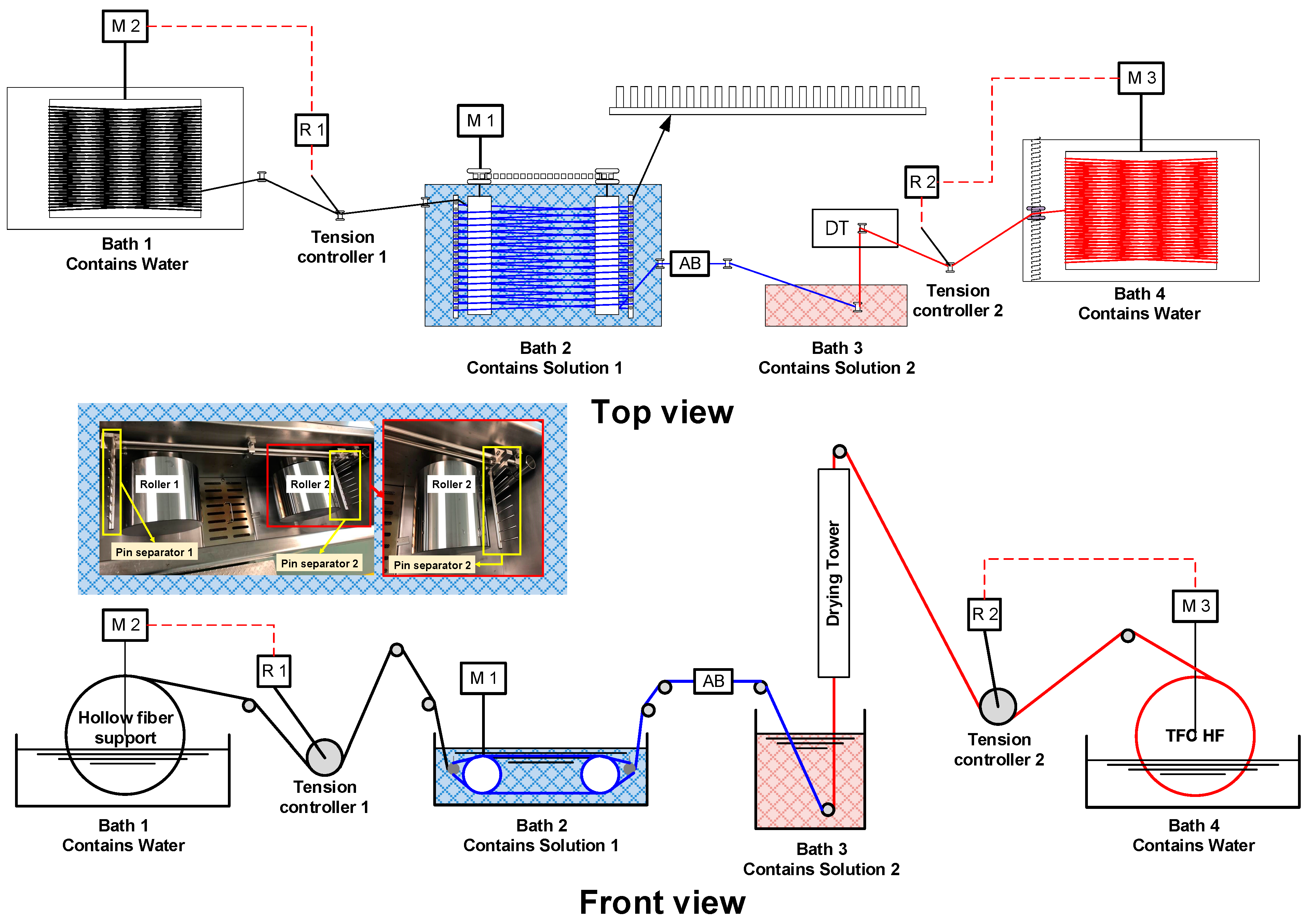
Figure 9.
Schematic representation of the phase inversion-based methods for HF membranes: (a) single layer, (b) double layer, (c) chemistry in the spinneret. The fabrication methods can be performed on the shell or the lumen side of the fiber. These methods can be applied to fabricate the support layer of TFC HF membranes for OSN applications. Reproduced from Ref. [27] under CCBY 4.0.

Figure 10.
Schematic illustration of interfacial polymerization (a) fabrication method with inner selective layer. Reproduced under CCBY 4.0 from Ref. [27]. Copyright 2022, Elsevier; (b) SEM image of the PEI–IPD selective layer on porous PP support. Reprinted with permission from Ref. [32]. Copyright 2008, Elsevier.

Figure 11.
Schematic representation of crosslinking treatment method. Reprinted with permission from Ref. [10]. Copyright 2019, American Chemical Society.
Figure 11.
Schematic representation of crosslinking treatment method. Reprinted with permission from Ref. [10]. Copyright 2019, American Chemical Society.

Figure 12.
Schematic illustration of the solvent activation of PEI–TMC TFC membrane. Reprinted with permission from [110]. Copyright 2020, American Chemical Society.
Figure 12.
Schematic illustration of the solvent activation of PEI–TMC TFC membrane. Reprinted with permission from [110]. Copyright 2020, American Chemical Society.

Figure 13.
(A) Schematic representation of a hollow fiber module. (B) Inside-out vs. outside-in filtration. Reproduced from [27] with permission of Elsevier.
Figure 13.
(A) Schematic representation of a hollow fiber module. (B) Inside-out vs. outside-in filtration. Reproduced from [27] with permission of Elsevier.

Figure 14.
Schematic of conventional OSN membranes lifecycle. Reproduced under CCBY 4.0 from Ref. [127].
Figure 14.
Schematic of conventional OSN membranes lifecycle. Reproduced under CCBY 4.0 from Ref. [127].

Figure 15.
Price of common organic solvents (in USD per liter, 2023) used for the fabrication of OSN membranes. The prices were based on purity of ≥99% (i.e., ReagentPlus and extra pure grades, according to the manufacturer). The prices were obtained from the databases of Sigma Aldrich (St. Louis, MO, USA) and Thermo Fisher Scientific (Waltham, MA, USA) (accessed on 15 December 2023). On the left panel, solvents were classified based on GlaxoSmithKline (GSK) (Tokyo, Japan) solvent sustainability guide [143].

Figure 16.
Sustainable lifecycle of recyclable “one monomer–two polymers–one monomer” membranes for organic solvent nanofiltration (OSN): ring-opening polymerization (ROP) and ring-opening metathesis polymerization (ROMP) of hybrid lactone-olefin monomer that yielded P(BiL=)ROP and P(BiL=)ROMP polymer structures; both polymers can be fabricated into OSN membranes using a γ-butyrolactone green solvent. Membrane fabrication: the dope solution containing polymer and green solvent is cast, and the formed film is immersed in a water coagulation bath, followed by annealing. Reproduced from [161] under CCBY 4.0.

Figure 17.
Chemical structure and price of common monomers used for fabricating HF OSN membranes. Green color refers to monomers used for fabricating bio-based TFC membranes (they are reported by the studies shown in Table 4); red color refer to the fossil-based monomers. The prices were based on mass basis of 1 KG and obtained from the databases of Sigma Aldrich [163] and Thermo Fisher Scientific [164].

Figure 18.
(a) The comparison between linear design and inverse design for developing nanofiltration membranes from conceptualization to industrial application. (b) The four pillars of developing membrane materials and processes, based on available data. Reproduced from [175] under CCBY 4.0.
Figure 18.
(a) The comparison between linear design and inverse design for developing nanofiltration membranes from conceptualization to industrial application. (b) The four pillars of developing membrane materials and processes, based on available data. Reproduced from [175] under CCBY 4.0.


Table 1.
Classification of membrane processes according to their driving forces. Adapted from [5] under CCBY-4.0.
Table 1.
Classification of membrane processes according to their driving forces. Adapted from [5] under CCBY-4.0.
| Driving Force | Pressure Difference (DP) | Osmotic Pressure Difference (Δπ) [Solvent Chemical Potential Gradient (Δμ)] | Concentration Difference (ΔC) | Temperature Difference (ΔT) | Electrical Potential Difference (Δf) |
|---|---|---|---|---|---|
| Phenomenological equation | Darcy’s law | Fick’s law | Fick’s law | Fourier’s law | Ohm’s law |
| Membrane operations | MF | FO | GS | MD | ED |
| UF | PV | EO | |||
| NF | D | ||||
| OSN | OSFO | ||||
| OSRO | |||||
| RO | RO |
Table 2.
Advantages and disadvantages of the fabrication and post-treatment methods for HF OSN membranes.
Table 2.
Advantages and disadvantages of the fabrication and post-treatment methods for HF OSN membranes.
| Method | Advantage | Disadvantages |
|---|---|---|
| Single-layer phase inversion |
|
|
| Dual-layer phase inversion |
|
|
| Interfacial Polymerization (TFC) |
|
|
| Incorporating fillers (MMM, TFN) |
|
|
| Post-treatment methods | ||
| Crosslinking |
|
|
| Solvent activation and Acid/alkali doping |
|
|
| Thermal annealing |
|
|
Table 3.
Summary of OSN HF membranes reported in the literature.
| Selective Layer | Support Layer | Membrane Active Area (cm2) | Membrane Type | Filtration Type | Solute | Solute MW (g mol−1) | Rejection (%) | Solvent | Permeance (L m−2 h−1 bar−1) | Pressure (bar) | Operation (days) | Ref. |
|---|---|---|---|---|---|---|---|---|---|---|---|---|
| PANi | PANi | ~79 | Single layer | - | Oligostyrene | 400 | ~93 | Acetone | 1.50 | 6 | Screening | [105] |
| PEI/IPD | PP | 9 | TFC | Inside-out | SO BBR | 351 826 | 43 88 | Methanol | 1.47 | 4.13 | Screening | [32] |
| PBI | Crosslinked PI | 50 | Dual layer | Outside-in | MB | 319.85 | 99.17 99.55 | Methanol Acetonitrile | 2.60 1.58 | 1 | Screening | [78] |
| MPD–TMC | Crosslinked dual layer PI | ~45 | TFC | Outside-in | RBB | 626.54 | 99.3 | Methanol | 0.90 | 16 | Screening | [57] |
| PMDA–ODA PI/TiO2 | PMDA-ODA PI/TiO2 | 20 | MMM | Outside-in | FG | 808 | 90 | DMF | 2.5 | 10 | ~2 | [115] |
| PAI | PAI | ~16 | Single layer | Outside-in | RB | 1017.64 | 97.3 98.6 | Isopropanol DMF | 6.4 0.9 | 2 | 7 3 | [101] |
| PAN | PAN | 19 | Single layer | Outside-in | RBB | 626.54 | 99.9 | Ethanol | 2.32 | 2.8 | Screening | [102] |
| PI/NH2–MWCNTs | PI | - | MMM | Outside-in | MB BBR RBB TC | 319.85 826 626.54 444.4 | 99.8 99.9 99.9 97.4 | Isopropanol Acetone Methanol Ethanol | 0.53 4.31 2.26 1.17 | 5 | 2.5 | [80] |
| Polyamide 6 | Polyamide 6 | 2.59 | Single layer | Inside-out | Vitamin B12 | 1355 | 98 | Methanol | 0.21 | 3 | Screening | [116] |
| Cellulose | Cellulose | - | Single layer | Outside-in | CR BBR | 696 826 | >90 ~40 | Ethanol | 6 | 0.2 | 1 | [117] |
| MPD–TMC/TiO2@rGO | Si3N4/PAN | 22 | TFN | Outside-in | BTB RB | 624 1017.64 | 95 98 | Ethanol | ~4.6 ~3.3 | 8 | Screening | [62] |
| PIM–1/AlOx | Crosslinked PI | - | TFN | Outside-in | RB | 1017.64 | 86 | Ethanol | ~1.5 | 0.69 | Screening | [118] |
| PBI | PBI | 20.10 | Single layer | Outside-in | MB RB | 319.85 1017.64 | ~99 ~99 | Acetone Methanol | ~4 ~1 | 5 | Screening 1 | [46] |
| GO | Crosslinked polyetherimide | 4.73 | TFN | Outside-in | RB | 1017.64 | 91 | Acetone | 4 | 1 | Screening | [94] |
| PI/FTB | Crosslinked polyetherimide | - | Dual layer | Outside-in | TC | 444.4 | >99 | Methanol | 3.7 | - | Screening | [46] |
| PEI/PIP–TMC | Crosslinked PI | ~32 | TFC | Inside-out | AF RB | 585 1017.64 | 90.3 99.9 | Acetone Isopropanol | 10.8 4.5 | 2 | 3 Screening | [58] |
| PAN | PAN | 23 | Single layer | Outside-in | EB MB | 960.81 319.85 | 100 71.5 | Methanol | 1.28 | 3 | 7 Screening | [113] |
| PI | PI | - | Single layer | Outside-in | RDB | 479 | 96.5 | Ethanol | 0.45 | 10 | Screening | [119] |
| PI | Modified PET braids with alkaline treatment | 2000 | Composite | Outside-in | TC | 444.4 | 99.2 | DMF Methanol | 2.03 4.94 | 6 | Screening | [71] |
| MPD–TMC | Crosslinked PI | 724 | TFC | Inside-out | MR MR Levofloxacin MO AF RB | 269 269 361 327 585 1017.84 | 90 90.1 98.2 98.6 99.4 99.8 | Acetone | 23.5 24.2 | 2 | 7 Screening | [59] |
| Polyamide 6 | Polyamide 6 | 60 | MMM | Inside-out | Vitamin B12 | 1355 | >99 | Methanol | 0.1 | 8 | Screening | [120] |
| PAI | PAI | ~9 | Single layer | Outside-in | MB VbB | 319.85 506.1 | 99.7 99.9 | Methanol | 1 1.87 | 2 | Screening | [121] |
| PBI | PBI | 2200 | Single layer | Outside-in | MO RBB TG | 327.33 626.54 885 | 77.5 99.5 99 | Acetone | 1.85 1.95 0.35 | 10 | Screening 30 | [104] |
| PI | PI | - | Single layer | Outside-in | RDB | 479.01 | 98 | Ethanol | 1.83 | 10 | Screening | [70] |
| PPy | Braid reinforced PPTA | ~25 | Composite | Outside-in | MB Eosin Y CR | 319.85 647.89 696.7 | 84.5 93.4 99.3 99.5 | DMAc Ethanol | 1.04 1.10 1.17 1.64 | 6 | Screening | [112] |
| MPD–TMC/GO | Crosslinked PI | 0.17 | TFC | Outside-in | RDB RB | 479.01 1017.84 | ~100 99 | Ethanol Methanol | 1.80 5.80 | 5 | Screening | [59] |
| BTCA–TAPA/COF | Crosslinked PI | 0.44 | TFC | Inside-out | L-α-lecithin FG RB | 758 808 1017.84 | ~100 98.9 99.5 ~99 92 99.1 | Hexane Acetone Isopropanol Ethanol Isopropanol | 266.27 395.21 61.68 ~50 98.44 61.68 | 1 | Screening 7.29 Screening | [61] |
| PBI | PET | 544 | Composite | Outside-in | RB | 1017.84 | 99.5 | Methanol | 3.60 1.37 | 10 | Screening ~3 | [48] |
| PEI/SMA | PVDF | - | Composite | Outside-in | MO CV | 327.3 407 | 99.9 ~98 | Ethanol | 6.4 1.90 0.70 | 1 | Screening 1 | [63] |
| PEI–TMC PEI/PIP–TMC | PTFE modified with PDA coating | 6 | TFC | Inside-out | AF MO | 585 327.3 | 94.8 93 99.9 95.4 | DMF DMF | 3.70 2.44 1.79 | 2 | Screening 3 Screening | [64] |
SO: safranin O; BBR: brilliant blue R; MB: methylene blue, RBB: Remazol brilliant blue; FG: fast green; RB: rose Bengal; TC: tetracycline; CR: Congo red; BTB: bromothymol blue; AF: acid fuchsin; EB: Evans blue; RDB: rhodamine B; MR: methyl red; MO: methyl orange; VbB: Victoria blue B; TG: triglycerides; CV: crystal violet. PANi: polyaniline; PEI: polyethyleneimine; PP: polypropylene; IPD: isophthaloyl dichloride; PBI: polybenzimidazole; PI: polyimide; MPD: M-phenylenediamine; TMC: trimesoyl chloride; PMDA-ODA: poly(4,4′-oxydiphenylene pyromellitimide); PAI: polyamide-imide; PAN: polyacrylonitrile; PIM: polymer of intrinsic microporosity; GO: graphene oxide; FTB: 4-Fluoro-2-(trifluoromethyl) benzylamine; PPy: polypyrrole; PPTA: poly(p-phenylene terephthamide); BTCA: benzene-1,3,5-tricarboxaldehyde; TAPA: tris(4-aminophenyl)amine; SMA: styrene maleic anhydride copolymer; TEA: triethylamine; EGDGE: ethylene glycol diglycidyl ether; TAEA: tris(2-aminoethyl)amine; SCA8: 4-sulfocalix [8]arene; DMAc: N,N-dimethylacetamide.
Table 4.
Summary of OSN TFC membranes using bio-based monomers via IP, as reported in the literature.
Table 4.
Summary of OSN TFC membranes using bio-based monomers via IP, as reported in the literature.
| Selective Layer | Support Layer | Membrane Active Area (cm2) | Solute | Solute MW (g mol−1) | Rejection (%) | Solvent | Permeance (L m−2 h−1 bar−1) | Pressure (bar) | Operation (Days) | Ref. |
|---|---|---|---|---|---|---|---|---|---|---|
| Chitosan and FDA | Recycled PET | 52 | MO RB | 327.33 1017.64 | 91.6 ~100 | Acetone | 11.9 | 10 | 14 | [136] |
| Priamine–genipin | PLA with gelatin as the interlayer layer | 28 | Oleuropein AF | 540.51 585.54 | 99 100 | Acetone | 9.9 | 30 | 7 | [138] |
| Priamine–TA | Recycled PET | 52 | Methyl styrene dimer | 235 | ~90 ~93 ~75 | Acetone Heptane Toluene | 13.5 ~2.5 ~3.5 | - | 7 | [139] |
| Quercetin–TPC | Cellulose | 12.6 | SO MO TB AB BB Reactive black Reactive green | 248.28 327.33 466.59 595.50 792.84 991.80 1418.93 | 58 90 94 96 97 98 100 | DMF | 2.6 2.4 2.7 2.6 2.4 2.6 2.8 | 10 | Screening | [146] |
| TA–TPC | Crosslinked PAN | 12.6 | CR BB RB | 696.66 825.97 1017.64 | 88 95 93 | NMP | 0.09 0.08 0.08 | 20 | Screening | [165] |
| Morin hydrate–TPC | Crosslinked PAN | 12.6 | Solvent blue 35 Polystyrene CR RBB BB RB | 350 500 590.71 626 825.97 1017.64 | 62 93 89 94 96 97 | NMP | 0.1 0.06 0.5 0.2 0.3 0.2 | 20 | Screening | [166] |
| Catechin–TPC | Cellulose | 12.6 | AB | 617 | 92 | DMF | 1.4 | 10 | Screening | [147] |
| Cyclodextrin–TMC | Crosslinked PI | - | RBB | 626 | 98.8 | Ethanol | 2.9 | 10 | Screening | [167] |
MO: methyl orange; RB: rose Bengal; AF: acid fuchsin; SO: Sudan orange; TB: thymol blue; AB: amido-black; BB: brilliant blue; CR: Congo red; RBB: Remazol brilliant blue; FDA: 2,5-furandicarboxaldehyde; PET: polyethylene terephthalate; PLA: polylactic acid; TA: tannic acid; TPC: terephthaloyl chloride; PAN: polyacronitrile; TMC: trimesoyl chloride; PI: polyimide.
Disclaimer/Publisher’s Note: The statements, opinions and data contained in all publications are solely those of the individual author(s) and contributor(s) and not of MDPI and/or the editor(s). MDPI and/or the editor(s) disclaim responsibility for any injury to people or property resulting from any ideas, methods, instructions or products referred to in the content. |
© 2024 by the authors. Licensee MDPI, Basel, Switzerland. This article is an open access article distributed under the terms and conditions of the Creative Commons Attribution (CC BY) license (https://creativecommons.org/licenses/by/4.0/).
Share and Cite
MDPI and ACS Style
Alammar, A.Y.; Choi, S.-H.; Buonomenna, M.G. Hollow Fiber Membrane Modification by Interfacial Polymerization for Organic Solvent Nanofiltration. Processes 2024, 12, 563. https://doi.org/10.3390/pr12030563
AMA Style
Alammar AY, Choi S-H, Buonomenna MG. Hollow Fiber Membrane Modification by Interfacial Polymerization for Organic Solvent Nanofiltration. Processes. 2024; 12(3):563. https://doi.org/10.3390/pr12030563
Chicago/Turabian StyleAlammar, Abdulaziz Y., Seung-Hak Choi, and Maria Giovanna Buonomenna. 2024. "Hollow Fiber Membrane Modification by Interfacial Polymerization for Organic Solvent Nanofiltration" Processes 12, no. 3: 563. https://doi.org/10.3390/pr12030563
Note that from the first issue of 2016, this journal uses article numbers instead of page numbers. See further details here.