

Circular Fluid Heating—Transient Entropy Generation


Faculty of Mechanical Engineering Tuzla, Department of Thermal and Fluid Technique, University of Tuzla, 75000 Tuzla, Bosnia and Herzegovina
Fluids 2024, 9(5), 119; https://doi.org/10.3390/fluids9050119
Submission received: 17 March 2024
/
Revised: 3 May 2024
/
Accepted: 17 May 2024
/
Published: 18 May 2024
(This article belongs to the Special Issue Evaporation, Condensation and Heat Transfer)
Abstract
:A technical issue with fluid flow heating is the relatively small temperature increase as the fluid passes through the heating surface. The fluid does not spend enough time inside the heating source to significantly raise its temperature, despite the heating source itself experiencing a substantial increase. To address this challenge, the concept of the multiple circular heating of air was developed, forming the basis of this work. Two PTC heaters with longitudinal fins are located within a closed channel inside housing composed of a thermal insulation material. Air flows circularly from one finned surface to another. Analytical modeling and experimental testing were used in the analysis, with established restrictions and boundary conditions. An important outcome of the analysis was the methodology established for the optimization of the geometric and process parameters based on minimizing the transient thermal entropy. In conducting the analytical modeling, the temperature of the PTC heater was assumed to be constant at 150 °C and 200 °C. By removing the restrictions and adjusting the boundary conditions, the established methodology for the analysis and optimization of various thermally transient industrial processes can be applied more widely. The experimental determination of the transient thermal entropy was performed at a much higher air flow rate of 0.005 m3s−1 inside the closed channel. The minimum transient entropy also indicates the optimal time for the opening of the channel, allowing the heated air to exit. The novelty of this work lies in the controlled circular heating of the fluid and the establishment of the minimum transient thermal entropy as an optimization criterion.
1. Introduction
Convective fluid heating occurs within channels of various shapes and dimensions, allowing heat to pass from the heater to the fluid either directly or indirectly. The convective surface is typically finned, increasing the total heat transfer absorbed by the fluid. In addition to increasing heat exchange, a more compact convective surface also results in a pressure drop in the fluid. Therefore, maximizing the heat transfer by using finned heating channels results in an increase in hydraulic fluid losses. In many process heating systems, an electric heater integrated onto the finned surface serves as the heat source. Typically, a constant heat flux is maintained between the convective surface of the heater and the fluid, while the surface temperature varies. Additionally, heaters of different shapes and sizes are positioned within the channel to convectively heat the fluid. A circular fluid flow within a closed loop and the thermal interaction of the fluid with the heat source and heat receiver are common in various process applications. Many researchers have analyzed and examined the forced cooling and heating of fluids within closed loops, focusing on the heat exchange between the heat source and the heat sink. Experimental testing of the natural heating of different fluids within a closed loop was conducted by several researchers, i.e., Ma, Lei et al. [1], Archana et al. [2], Thippeswamy and Kumar [3], Mukund and Santanu [4], Sharma et al. [5], and Zixu Hu et al. [6]. Some researchers have analyzed the heat transfer within closed loop pulsating and oscillating heat pipes, including Rittidech et al. [7], Dehshali et al. [8], Ando et al. [9], and Song et al. [10]. Heat transfer inside closed concentric channels with forced fluid circulation was investigated by Jilte et al. [11] and Mustafa et al. [12]. Closed channels for fluid transfer between the heat source and sink can be found in various technical systems and devices, and some examples are engine cooling, geothermal heating, and solar panels. Heat transfer within a closed loop containing thermoelectric generators, a compact heat sink, and a working fluid has been analyzed by several researchers, such as Songkran and Paisarn [13] and Siddique et al. [14]. Many researchers have analyzed the effects of various convective elements within different tubes on the heating efficiency, such as Chang et al. [15], Chyu [16], Hsiao et al. [17], and Wang et al. [18]. Alic [19] specifically studied the combination of profiled heating elements of different inline power placed inside the channel and their influence on the total irreversibility. The generation of entropy within various geometric structures through which a fluid flows was investigated by Bishwaranjan et al. [20], Antonio [21], and Mei et al. [22]. The analysis of entransy and the minimization of entransy dissipation in various cross-sections of a tube heat exchanger was performed by Wei et al. [23] and Alic [24]. Wu and Liang [25] also analyzed the extremum of entransy dissipation, even considering established radiative heat transfer. In this analysis, an analytical model of the thermal and hydraulic entropy resulting from a fluid flow through heating elements is implemented. Building on previous analyses and research, a concept is introduced in which the fluid undergoes multiple heating cycles before exiting the heating channel. Typically, the fluid flows through convective heating surfaces, becomes heated, and then exits the heating device. In order to achieve the required temperature of the fluid, the electric power of the heating sources is increased or its flow is reduced. These two procedures cannot always be applied in process systems. Therefore, in the analysis conducted in this paper, air is heated multiple times within the channel using two installed finned heating sources. The closed circular channel inside the thermal insulation case is connected to the inlet and outlet pipelines with valves installed. Air flow inside the channel is facilitated by an axial fan. Once the desired temperature is reached, the outlet channel is opened, allowing the hot air to exit the housing, while the process of heating the incoming air continues.
2. Methodology
2.1. Analytical Approach
Two finned heating surfaces with straight longitudinal fins are located inside profiled housing composed of a thermal insulation material. The heating of the finned surfaces is achieved by electric PTC heaters, which maintain a constant temperature at the bottom of the fins; see Figure 1. In the analytical approach conducted, it is assumed that the temperature of the heat sources remains constant throughout the heating process. The circular flow of air through the heating fins is provided by an axial fan. During the air heating process, the inlet and outlet channels of the housing are closed, while the air flows in a circular pattern through both heaters; see Figure 1a. The air temperature at the exit from the first PTC heater A, labeled A, represents the temperature entering PTC heater A, and the heating process is continuously repeated. The total length of the duct shown in Figure 1 is not depicted to scale, as a schematic of the circular air heating system was needed for the analytical modeling that was conducted. After the air circulates through both heaters, its temperature reaches the required level. At this point, the outlet channel opens (Figure 1b). Once the hot air exits the housing, the outlet channel closes, and the process begins again with unheated air entering through the inlet channel. The analysis conducted was based on analytical modeling. In this sense, the following assumptions were adopted regarding the geometric and physical process quantities:
- −
- hydraulic irreversibilities were not considered in the analysis presented in this paper;
- −
- heat exchange with the environment was minimized and neglected in the analytical modeling;
- −
- the effects of sudden fluid (air) deflection, local fluid mixing, and frictional forces on heat exchange were also not considered in this work;
- −
- it was assumed that the inlet temperature of the air in the housing remained constant;
- −
- the physical properties of the air and housing materials were based on average temperature values.
The heat balance analyzed in this study indicates the forced circular convective heating of the air inside the housing channel. The convective surface includes both the fins and the interfin surface on both finned surfaces. For case A, the temperatures of both PTC heaters are the same (tfo.1 = tfo.2 = tfo). The heat balance is established within the sections of both heating finned sources and the fluid (air), according to Equation (1). It is assumed that the current mean air temperature inside the entire enclosure is constant and increases over time. The final air temperature equals the required temperature for the heating process. The established methodology allows for the possibility that both finned heaters have different dimensions and characteristics. In the analyzed case A, the transient air temperature is determined from the balance.
And, after separating the variables,
by maintaining consistent average air temperatures
where and .
After integrating Equation (2), the transient temperature of the air inside the profiled heated housing is determined as
where Va is the volumetric air flow through the channel, τ is the time, ρa is the air density, ηf is the fin efficiency, ca is the specific heat capacity of the air, υa is the kinematic viscosity of the air, ta.o is the initial air temperature, tfo is the temperature of the interfin surface and the bottom of the fin, and α1 and α2 are the convective heat transfer coefficients in the finned heating sources. The temperature of the finned surface (tfo) is kept constant by utilizing a PTC heater located as shown in Figure 1. In case B, the temperatures of the two PTC heaters (tfo.1, tfo.2) differ, resulting in a transient change in the air temperature that is calculated from the balance.
After separating the variables and integrating them, we obtain the transient air temperature as shown in Equation (6).
In the previous equations, the conductive coefficient of heat transfer within the channel is calculated according to Expression (7). The convective heat transfer coefficient for the case of a fluid flow between two vertical parallel walls (longitudinal fins), according to Teertstra et al. [26], is
where the modified Reynolds number is
while δf is the fin thickness, ReDh is the channel Reynolds number, Dh is the hydraulic diameter of the channels, wch is the fluid velocity inside the channel, wa.o is the the velocity of the fluid immediately before entering the channel, and δ is the fin spacing. The mean temperature of the fin at its height h was obtained according to the boundary conditions; (a) the temperature at the bottom of the fin has a constant value tfo and (b) the top of the fin is thermally insulated, so it can be represented by the expression
where m = (αP/λfAf)0.5 is the fin parameter, P is the fin perimeter, Af is the cross-sectional area of the fin, and λf is the conductive heat transfer coefficient of the fin. The characteristic dimensions of the channels and finned surfaces and the process characteristics of the analyzed circular air heating system are shown in Table 1.
During the process of circulating air inside a closed channel with finned PTC heating sources, the temperature of the air steadily increases at a constant temperature. In the analysis conducted, the average temperature of the fin along its length L is utilized. This results in heat exchange between the finned heating sources and the air flowing within the housing channel, leading to transient thermal irreversibilities and thermal entropy. For the analyzed cases A and B, the transient thermal entropy of the air in the process of circular heating can be represented by Expressions (11) and (12), respectively.
where The transient thermal entropy of the PTC heating source includes the thermal irreversibility of its finned and non-finned surfaces inside the housing. The temperature of the fins is taken as the average value (Tf.avr), while the temperature of the surface between the fins remains constant (Tfo). In case A, the thermal entropy of the heat source is represented as
while, for case B,
2.2. Experimental Approach
To validate the results obtained from the analytical modeling, a test module was constructed to closely match the previously modeled system. The module included two PTC heaters situated inside thermal insulation housing within a square cross-section channel, as shown in Figure 2. The inlet air temperature and the temperature of the first heater were measured using an Omega Engineering temperature humidity meter, model HH314. The air temperature inside the housing of one heater was measured using a Lutron TM-917 thermometer (Lutron Electronics Co., Inc., Coopersburg, PA, USA) with precision of 0.01 degrees. The air flow was measured with a Lutron YK-2005AH hot wire anemometer. The geometric characteristics of the housing and the finned surface and the power of the heater are detailed in Table 1. The air thermal entropy was indirectly determined through experimental temperature measurements. The air temperature was directly measured and approximated by a polynomial function that was differentiated with respect to time. A finned heating surface with longitudinal heating fins and an installed PTC heater is shown in Figure 2. The thermogram of the described heating system is also depicted in the same figure. For the experimental test, two heating assemblies (finned surface and heater) with varying temperatures and power levels were utilized.
During the test, the volumetric air flow was constant. The thermal entropy of the heating sources was also determined using the same method, resulting in the total thermal entropy of the analyzed heating system as shown in Equation (15).
where , , ,
3. Results and Discussion
The analysis involved studying convective air heating inside a closed channel within heat-insulating casing measuring a total length of 1.3 m. Two PTC heaters are positioned inside the channel on a longitudinal finned surface with a total length of 0.1 m. The volumetric air flow and duration of heating are variable and limited to 0.00006 m3s−1 and 60 s, respectively. Constant temperatures of 150 °C and 200 °C are maintained using PTC heaters. The initial air temperature inside the housing is 20 °C. In both cases, A and B, two identical finned surfaces were used with the geometric parameters outlined in Table 1. In case A, both heaters had the same temperature of 150 °C, so the change in air temperature was as depicted in Figure 3a. Additionally, in Figure 3b, the change in air temperature at a constant temperature of 200 °C in both heating sources is shown. A rapid increase in the air temperature occurs with an increase in air flow and heating time. The maximum air heating time is 60 s. In Figure 3b, one heating source has a temperature of 150 °C, while the other has a temperature of 200 °C. The flow rate and heating time were varied in the experiment. In addition to the increase in the temperature of the PTC heating sources, the rapid rise in the air temperature is influenced by the duration of heating and the volume of the air flow. The air continuously flows in a circular manner through the finned heating channels, ensuring constant heating. As the air flow rate increases, so does the frequency of heating by both PTC heaters, as illustrated in Figure 3.
The thermal entropy of the air during a circular flow in a closed channel is illustrated in Figure 4. The analysis did not consider hydraulic entropy. The significant increase in the thermal entropy of the air was due to the rise in the temperature of the heating sources, from 150 °C to 200 °C. In Figure 4a, the temperatures of the heating sources are different and constant, while Figure 4b shows a constant temperature of 200 °C for both heating sources. The maximum temperature of the heated air over time also indicates the peak value of its transient thermal entropy. At low air flows, the temperature change of the PTC heater does not have a significant impact. This is because only a small volume of air inside the finned PTC heaters overheats locally, rather than the entire volume of air in the ducts.
The thermal entropy of the heating source has a negative value and increases in absolute value with the increase in volumetric air flow, as shown in Figure 5. In Figure 5a, the temperatures of the heating sources are different and constant, while Figure 5b shows both heating sources at a constant temperature of 200 °C. The maximum value of the transient thermal entropy of heating in the PTC sources occurs at the beginning of heating and with the highest air flow. Under these conditions, the maximum heat flux between the PTC heater and the air is established. Therefore, due to the high value of the convective heat transfer coefficient and the largest temperature difference between the surface of the PTC heating sources and the air, the maximum heat flux occurs. As a result, the thermally generated entropy of the heat sources reaches its maximum values.
According to the established circular process of air heating inside the profiled closed channel, the required final temperature depends on several factors. With constant temperatures of the two heating sources at 150 °C and 200 °C, and at an air flow rate of 0.00005 m3s−1, during 60 s of heating, the increase in the air temperature is as shown in Figure 6. Since the total length of both heating sources is 0.2 m and the length of the closed channel is 1 m, the air flows cyclically 15 times through each heating source in the course of 60 s. The total number of circulations depends on the volumetric air flow and the cross-sectional area through which the air flows. Once the temperature reaches about 177 °C, the outlet channel opens and the hot air exits the housing. The dashed line indicates the approximate linear outflow of air over a 4 s period after opening the channel. The process of opening and closing the channel can be automated, making it a reliable application in various process systems. The process of heating the air that enters the housing continues even after the outlet valve is closed, as shown in Figure 1 and Figure 6.
If the volumetric air flow through the channel increases several times, reaching values of 0.005 m3s−1 and 0.01 m3s−1, the required air temperature of 177 °C can be achieved in up to 10 s, as shown in Figure 7a. A higher volumetric air flow results in an increased air velocity and a shorter time to reach the required temperature during circular heating. Under the same process conditions, if the air is heated in an open channel during a single passage, the exit temperature of the air is significantly lower (see Figure 7b). In comparison to the previous scenario, the air outlet temperature decreases because of the shorter heating time within both channels, which have a total length of 0.2 m. At a lower flow rate of 0.005 m3s−1, the outlet air temperature is approximately 52 °C, which is 120 °C lower compared to air circulation heating at the same flow rate (see Figure 7a). Since the duct is closed, the air is trapped inside and flows in a circular motion over both PTC heating sources. This means that a higher flow of air directly results in a faster heating time, reaching the maximum temperature, as shown in Figure 7a. The air temperature increases linearly along the length of both PTC heating sources, each with a length of 0.1 m, as shown in Figure 7b. As the temperature of the PTC heater changes, the rate of the increase in the air temperature changes, as indicated by the dashed line.
In the conducted experimental testing, two PTC electric heaters were used and placed inside a closed channel with the characteristic dimensions shown in Table 1. The channel housing was thermally insulated from the ambient environment. An axial fan created a circular flow of air with a constant volumetric flow rate of 0.005 m3s−1 and an initial temperature of 20 °C. Inside the closed channel designed in this study, the air was consistently heated, resulting in higher temperatures for both heaters over the 300 s analyzed time interval (see Figure 8a). The temperatures of heaters A and B, as well as the air temperature, at 50 s from the start of heating, are shown in Figure 8. The temperatures of both heaters and the air temperature were approximated by polynomial functions. These functions, as described in Equations (15) and (16), were used to determine the thermal entropy.
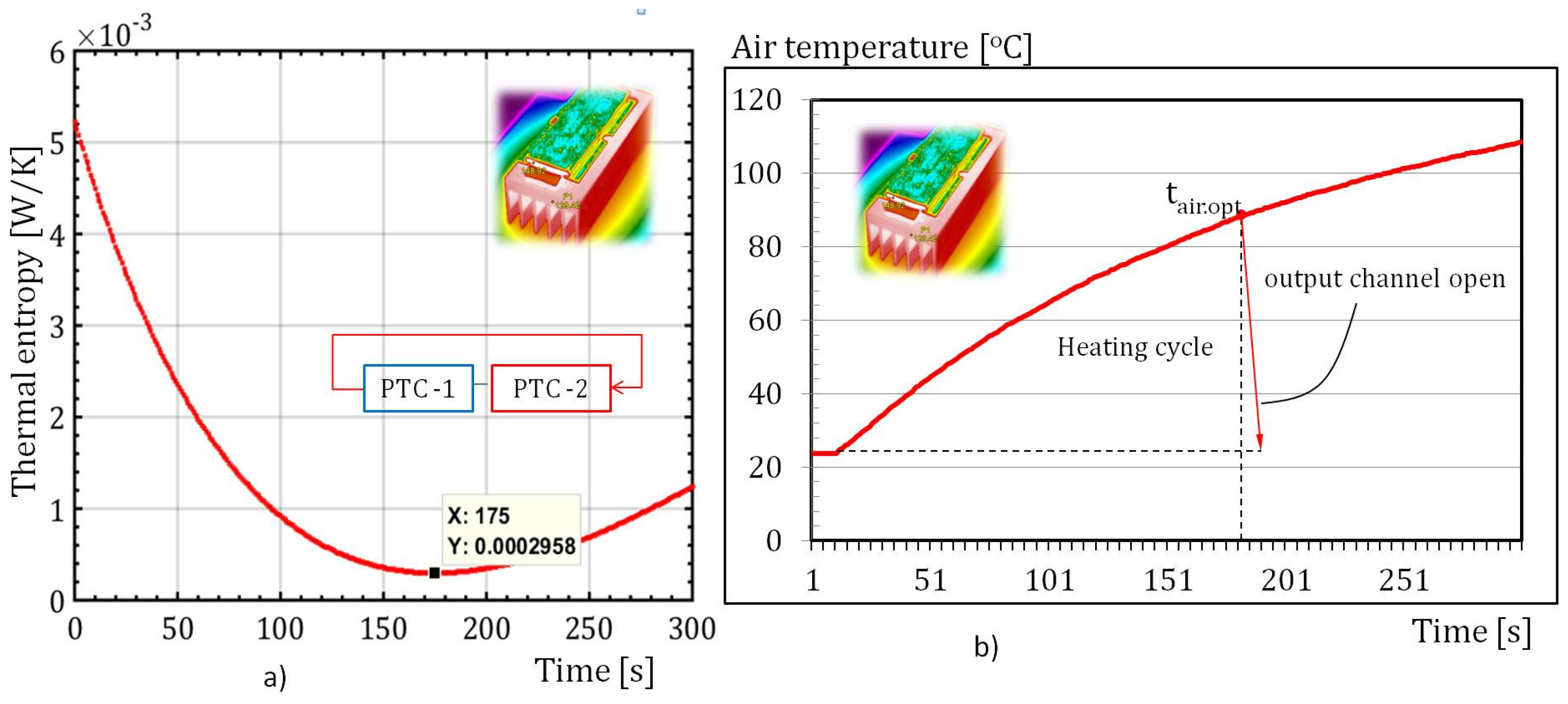
The total transient thermal entropy of the air and both heating sources during the circular heating process at a constant air volumetric flow rate of 0.005 m3s−1 is shown in Figure 9. The expressions obtained for the transient temperature of the heating sources and the air temperature, as shown in Figure 8, were used to calculate the total thermal entropy generated. The temperature of the PTC-1 heater increased from 140 °C to approximately 180 °C, while, for the PTC-2 heater, the temperature increased from 115 °C to approximately 158 °C in a time interval of 250 s (Figure 8a). During the same time interval, the air temperature rose from 20 °C to 115 °C. The total thermal entropy of a closed circular system with different temperatures is the sum of the individual entropies of the heating sources and the air. This is represented by the function in Figure 9. During the air heating process, the minimum thermal entropy occurs 175 s after the start of heating. When considering the minimum thermal entropy as an optimization criterion, the optimal time for the release of the fluid from the closed case is also 175 s after the start of heating, as shown in Figure 9a. The minimum transient thermal entropy represents the lowest amount of thermal irreversibility, which, in this context, indicates the optimal time for the release of air from the housing. In this case, the periodic release of the hot air from the circular channel is considered successful if both the air and the housing cool down to the initial temperature of 20 °C. As the internal temperature of the housing will increase during the heating of the air, the period of time for which the channel can stay open will be less than 175 s. According to Figure 9b, the optimal temperature for the release of the heated air from the housing is 88 °C. The duration of heating of the air inside the housing after 175 s will affect its temperature increase, as well as its thermal entropy.
The established methodology involving the transient thermal entropy enables the indirect minimization and determination of the optimal opening time for the casing output channel. By reducing the geometric and process limitations, it is possible to establish a general optimization criterion based on minimizing the transient thermal entropy. To improve the current methodology, the hydraulic entropy can be included in the calculation of the total entropy generation. In this case, the minimum of the total transient entropy would be the optimization criterion. It is clear that, in this case, there would be a correction to the results obtained in this analysis.
4. Conclusions
The current analysis proposes circular air heating through an air flow across two finned convective surfaces. The convective surfaces are heated using PTC heaters at varying temperatures. The paper focuses on the transient thermal entropy of the heating sources and air. The methodology in this work is based on two approaches, analytical modeling and experimental testing. In the case of using numerical modeling, it becomes possible to show local changes in the process variables in various sections of the circular housing and heating sources. The analytical model used in this analysis incorporates several interconnected equations from the heat balance and thermal entropy of the analyzed system. In the analyzed case, in addition to the thermal entropy caused by the heat flux, hydraulic entropy also occurs. Frictional and local resistances to the air flow through the circular casing cause hydraulic irreversibilities that are not included in this study. A significant increase in hydraulic irreversibilities is expected within the finned heating surfaces of both PTC electric heaters, caused by a greater drop in the air pressure. Additionally, experimental testing was conducted on circular air heating using two PTC electric heaters. The following findings were observed.
- From an analytical point of view, a mathematical model of the total thermal entropy is established as a function of the geometric and process parameters of the heating system. The analytical model is based on the constant temperatures of the PTC heaters, but it also allows for the consideration of transient temperatures of the heating sources.
- The established analytical model indicates the influence of the volumetric air flow and the temperature of the PTC heater on the transient temperature and thermal entropy of the air, as well as the thermal entropy of the PTC heater. The transient, thermally generated air entropy increases rapidly with the increase in the heating time and volumetric air flow inside the channel during circular heating. Additionally, a higher temperature in the heating source results in an increase in thermal entropy.
- From an experimental point of view, the temperatures of the PTC heaters are transient and the expressions for their rate of change over time can be incorporated into the established analytical model. The experimental results indicate a minimal amount of transient thermal entropy, which directly implies the optimal geometrical and process parameters of the circular heating system.
- By keeping the geometrical parameters constant in this analysis, the minimum transient thermal entropy determines the optimal time for air release from the casing.
- The minimum transient thermal entropy of the circular heating of air is the basis for the automation of the process of circular heating for any fluid. Furthermore, by removing the constraints imposed in this work, the optimization can be used for geometrical and process parameters.
By removing the defined limitations, the methodology developed in this paper can be extended to more general applications.
Funding
This research received no funding.
Data Availability Statement
The data are contained within the article.
Conflicts of Interest
The author declares no conflicts of interest.
Nomenclature
| Ta.A | air temperature in section A, K |
| Ta.B | air temperature in section B, K |
| Tfo.1 | fin base temperature in section A, K |
| Tfo.2 | fin base temperature in section B, K |
| Va | volumetric flow rate, m3s−1 |
| Afo | cross-sectional area of fin, m2 |
| Af | fin surface, m2 |
| h | fin height, m |
| L | heater length, m |
| Sgen.a | transient thermal entropy of air, WK−1 |
| Sgen.hs | heat source entropy, WK−1 |
| ca | specific heat capacity, Jkg−1K−1 |
| Dh | hydraulic diameter of channel, m |
| ReDh | channel Reynolds number, - |
| wa.o | air velocity in front of channel, ms−1 |
| wch | air velocity within channel, ms−1 |
| P | fin perimeter, m |
| Greek symbols | |
| δ | fin distance, m |
| δf | fin thickness, m |
| α | convective heat transfer coefficient, Wm−2K−1 |
| λ | conductive heat transfer coefficient, Wm−1K−1 |
| τ | time, s |
| υa | kinematic viscosity, m2s−1 |
| ρa | air density, kgm−3 |
| ηf | fin efficiency, - |
References
- Ma, L.; Zhao, X.; Sun, H.; Wu, Q.; Liu, W. Experimental Study of Single Phase Flow in a Closed-Loop Cooling System with Integrated Mini-Channel Heat Sink. Entropy 2016, 18, 128. [Google Scholar] [CrossRef]
- Archana, V.; Vaidya, A.M.; Vijayan, P.K. Flow Transients in Supercritical CO2 Natural Circulation Loop. Procedia Eng. 2015, 127, 1189–1196. [Google Scholar] [CrossRef]
- Thippeswamy, L.R.; Kumar Yadav, A. Heat transfer enhancement using CO2 in a natural circulation loop. Sci. Rep. 2020, 10, 1507. [Google Scholar] [CrossRef] [PubMed]
- Bade, M.H.; Bandyopadhyay, S. Targeting Minimum Heat Transfer Fluid Flow for Multiple Heat Demands. Comput. Aided Chem. Eng. 2012, 31, 675–679. [Google Scholar]
- Sharma, M.; Vijayan, P.K.; Pilkhwal, D.S.; Asako, Y. Asako Steady state and stability characteristics of natural circulation loops operating with carbon dioxide at supercritical pressures for open and closed loop boundary conditions. Nucl. Eng. Des. 2013, 265, 737–754. [Google Scholar] [CrossRef]
- Hu, Z.; Xu, T.; Feng, B.; Yuan, Y.; Li, F.; Feng, G.; Jiang, Z. Thermal and fluid processes in a closed-loop geothermal system using CO2 as a working fluid. Renew. Energy 2020, 154, 351–367. [Google Scholar] [CrossRef]
- Rittidech, S.; Sangiamsuk, S. Internal flow patterns on heat transfer performance of a closed-loop oscillating heat pipe with check valves. Exp. Heat Transf. 2012, 25, 48–57. [Google Scholar] [CrossRef]
- Dehshali, M.E.; Nazari, M.A.; Shafii, M.B. Thermal performance of rotating closed-loop pulsating heat pipes:Experimental investigation and semi-empirical correlation. Int. J. Therm. Sci. 2018, 123, 14–26. [Google Scholar] [CrossRef]
- Ando, M.; Okamoto, A.; Nagai, H. Start-up and heat transfer characteristics of oscillating heat pipe with different check valve layouts. Appl. Therm. Eng. 2021, 196, 117286. [Google Scholar] [CrossRef]
- Song, E.-H.; Lee, K.-B.; Rhi, S.-H.; Kim, K. Thermal and Flow Characteristics in a Concentric Annular Heat Pipe Heat Sink. Energies 2020, 13, 5282. [Google Scholar] [CrossRef]
- Jilte, R.; Ahmadi, M.H.; Kumar, R.; Kalamkar, V.; Mosavi, A. Cooling Performance of a Novel Circulatory Flow Concentric Multi-Channel Heat Sink with Nanofluids. Nanomaterials 2020, 10, 647. [Google Scholar] [CrossRef] [PubMed]
- Mustafa, J.; Alqaed, S.; Siddiqui, M.A. Thermally Driven Flow of Water in Partially Heated Tall Vertical Concentric Annulus. Entropy 2020, 22, 1189. [Google Scholar] [CrossRef] [PubMed]
- Wiriyasart, S.; Naphon, P. Thermal to electrical closed-loop thermoelectric generator with compact heat sink modules. Int. J. Heat Mass Transf. 2021, 164, 120562. [Google Scholar] [CrossRef]
- Siddique, A.R.M.; Muresan, H.; Majid, S.H.; Mahmud, S. An adjustable closed-loop liquid-based thermoelectric electronic cooling system for variable load thermal management. Therm. Sci. Eng. Prog. 2019, 10, 245–252. [Google Scholar] [CrossRef]
- Chang, S.W.; Gao, J.Y.; Shin, H.L. Thermal performances of turbulent tubular flows enhanced by ribbed and grooved wire coils. Int. J. Heat Mass Transf. 2015, 90, 1109–1124. [Google Scholar] [CrossRef]
- Chyu, M.C. Thermal analysis of the electrically heated cylindrical test section for heat transfer experiments. Exp. Therm. Fluid Sci. 1988, 1, 19–27. [Google Scholar] [CrossRef]
- Hsiao, S.Y.; Wei, P.S.; Wang, Z.O. Three-dimensional temperature field in a line-heater embedded by a spiral electric resistor. Appl. Therm. Eng. 2006, 26, 916–926. [Google Scholar] [CrossRef]
- Wang, M.C.; Chen, Y.P.; Wu, J.F.; Dong, C. Heat transfer enhancement of folded helical baffle electric heaters with one-plus-two U-tube units. Appl. Therm. Eng. 2016, 102, 586–595. [Google Scholar] [CrossRef]
- Alic, F. The non-dimensional analysis of nanofluid irreversibility within novel adaptive process electric heaters. Appl. Therm. Eng. 2019, 152, 13–23. [Google Scholar] [CrossRef]
- Samal, B.; Barik, A.K.; Awad, M.M. Thermo-fluid and entropy generation analysis of newly designed loops for constructal cooling of a square plate. Appl. Therm. Eng. 2019, 156, 250–262. [Google Scholar] [CrossRef]
- Miguel, A.F. A study of entropy generation in tree-shaped flow structures. Int. J. Heat Mass Transf. 2016, 92, 349–359. [Google Scholar] [CrossRef]
- Liu, M.; Li, S.; Wu, Z.; Zhang, K.; Wang, S.; Liang, X. Entropy generation analysis for grooved structure plate flow. Eur. J. Mech.—B/Fluids 2019, 77, 87–97. [Google Scholar] [CrossRef]
- Wei, S.; Chen, L.; Sun, F. Constructal Entransy Dissipation Minimization of Round Tube Heat Exchanger Cross-Section. Int. J. Therm. Sci. 2011, 50, 1285–1292. [Google Scholar] [CrossRef]
- Alic, F. Entransy Dissipation Analysis and New Irreversibility Dimension Ratio of Nanofluid Flow. Energies 2020, 13, 114. [Google Scholar] [CrossRef]
- Wu, J.; Liang, X. Application of Entransy Dissipation Extremum Principle in Radiative Heat Transfer Optimization. Sci. China Ser. 2008, 51, 1306–1314. [Google Scholar] [CrossRef]
- Teertstra, P.; Yovanovich, M.M.; Culham, J.R. Analytical forced convection modeling of plate fin heat sinks. J. Electron. Manuf. 2000, 10, 253–261. [Google Scholar] [CrossRef]
Figure 1.
(a,b) Multiple circular forced air heating systems utilizing two PTC heaters. Longitudinal fins beneath the PTC heaters enhance the total convective surface area between the heat source and the air.
Figure 1.
(a,b) Multiple circular forced air heating systems utilizing two PTC heaters. Longitudinal fins beneath the PTC heaters enhance the total convective surface area between the heat source and the air.

Figure 2.
An experimental test was conducted using a finned heating surface with longitudinal fins and a PTC heater installed.
Figure 2.
An experimental test was conducted using a finned heating surface with longitudinal fins and a PTC heater installed.

Figure 3.
The air temperature during a heating circular process varies depending on the scenario. In case (a), both heating sources have temperatures of 150 °C and 200 °C. In case (b), one heating source has a temperature of 150 °C, while the other has a temperature of 200 °C.
Figure 3.
The air temperature during a heating circular process varies depending on the scenario. In case (a), both heating sources have temperatures of 150 °C and 200 °C. In case (b), one heating source has a temperature of 150 °C, while the other has a temperature of 200 °C.

Figure 4.
(a,b) The transient thermal entropy of the air changes during the circular process of air heating. During the circular air heating process, the inlet and outlet channels of the housing are closed.
Figure 4.
(a,b) The transient thermal entropy of the air changes during the circular process of air heating. During the circular air heating process, the inlet and outlet channels of the housing are closed.

Figure 5.
(a,b) The transient entropy generation of the heat sources during the circular air heating process.
Figure 5.
(a,b) The transient entropy generation of the heat sources during the circular air heating process.

Figure 6.
Air heating cycles occur at various temperatures of the heating sources, such as 150 °C and 200 °C, with a volumetric flow rate of 0.00005 m3s−1.
Figure 6.
Air heating cycles occur at various temperatures of the heating sources, such as 150 °C and 200 °C, with a volumetric flow rate of 0.00005 m3s−1.

Figure 7.
Comparison of air temperature in a closed channel (a) and an open channel (b) at the same process parameters.
Figure 7.
Comparison of air temperature in a closed channel (a) and an open channel (b) at the same process parameters.

Figure 8.
Experimental testing involved measuring the temperature of the PTC heaters while heating (a) and the air temperature (b).
Figure 8.
Experimental testing involved measuring the temperature of the PTC heaters while heating (a) and the air temperature (b).

Figure 9.
(a,b) Total transient thermal entropy of a closed heating system with a circular air flow.
Figure 9.
(a,b) Total transient thermal entropy of a closed heating system with a circular air flow.

Table 1.
Geometrical parameters of the finned PTC heaters for circular air heating—analytical approach.
Table 1.
Geometrical parameters of the finned PTC heaters for circular air heating—analytical approach.
| L [m] | δf [m] | δ [m] | nf [-] | h [m] | ta.o [°C] | tf.o.1 [°C] | tf.o.2 [°C] | Heater Type | Fluid |
|---|---|---|---|---|---|---|---|---|---|
| 0.1 | 0.002 | 0.006 | 6 | 0.025 | 20 | 150 | 200 | PTC 230V ac, 75 × 35 × 8.5 mm | Air |
Disclaimer/Publisher’s Note: The statements, opinions and data contained in all publications are solely those of the individual author(s) and contributor(s) and not of MDPI and/or the editor(s). MDPI and/or the editor(s) disclaim responsibility for any injury to people or property resulting from any ideas, methods, instructions or products referred to in the content. |
© 2024 by the author. Licensee MDPI, Basel, Switzerland. This article is an open access article distributed under the terms and conditions of the Creative Commons Attribution (CC BY) license (https://creativecommons.org/licenses/by/4.0/).
Share and Cite
MDPI and ACS Style
Alic, F. Circular Fluid Heating—Transient Entropy Generation. Fluids 2024, 9, 119. https://doi.org/10.3390/fluids9050119
AMA Style
Alic F. Circular Fluid Heating—Transient Entropy Generation. Fluids. 2024; 9(5):119. https://doi.org/10.3390/fluids9050119
Chicago/Turabian StyleAlic, Fikret. 2024. "Circular Fluid Heating—Transient Entropy Generation" Fluids 9, no. 5: 119. https://doi.org/10.3390/fluids9050119