Article

Optimal Rotor Design and Analysis of Energy-Efficient Brushless DC Motor-Driven Centrifugal Monoset Pump for Agriculture Applications

by
Richard Pravin Antony
1,
Pongiannan Rakkiya Goundar Komarasamy
2,*,
Narayanamoorthi Rajamanickam
1,
Roobaea Alroobaea
3 and
Yasser Aboelmagd
4,*
1
Department of Electrical and Electronics Engineering, SRM Institute of Science and Technology, Kattankulathur 603 203, India
2
Department of Computing Technologies, SRM Institute of Science and Technology, Kattankulathur 603 203, India
3
Department of Computer Science, College of Computers and Information Technology, Taif University, P.O. Box 11099, Taif 21944, Saudi Arabia
4
College of Engineering, University of Business and Technology, Jeddah 23435, Saudi Arabia
*
Authors to whom correspondence should be addressed.
Energies 2024, 17(10), 2280; https://doi.org/10.3390/en17102280
Submission received: 25 March 2024 / Revised: 1 May 2024 / Accepted: 7 May 2024 / Published: 9 May 2024
(This article belongs to the Special Issue Applications of Electromagnetism in Energy Efficiency)

Abstract

:
The agricultural sector emphasizes sustainable development and energy efficiency, particularly in optimizing water pumping systems for irrigation. Brushless DC (BLDC) motors are the preferred prime mover over induction motors due to their high efficiency in such applications. This article details the rotor design and analysis of an energy-efficient BLDC motor with specifications of 1 hp, 3000 rpm, and 48 V, specifically tailored for a centrifugal monoset pump for irrigation. The focus lies in achieving optimal energy efficiency through grey wolf optimization (GWO) algorithm in the rotor design to determine optimal dimensions of the Neodymium Iron Boron (NdFeB) magnet as well as its grade. The finite element method analysis software, MagNet, is used to model and analyze the BLDC motor. The motor parameters, such as speed, torque, flux functions, temperature, and efficiency, are analyzed. For performance comparison, the same model with different magnet models is also analyzed. Validation via 3D finite element analysis highlights improvements in magnet flux linkage, stator tooth flux density, and rotor inertia with increased magnet thickness. Simulation results affirm the consistent performance of the designed BLDC motor, preferably when efficiency is increased. This efficiency and the constant speed lead to an improvement in the overall conversion efficiency of 7% within its operating range, affirming that the motor pump system is energy-efficient.

1. Introduction

In the past decade, energy prices have increased due to the depletion of fossil fuels. Appliances with energy efficiency are the need of the day. The major sources of energy consumption in agriculture applications of groundwater water pumping include surface and submersible pumps, irrigation systems, livestock care, and domestic needs [1,2]. Electric motors account for approximately two-thirds of global industrial electricity usage and contribute to half of the global domestic electricity usage. Notably, pumping systems autonomously consume nearly one-fourth of the overall electricity utilized by electric motors worldwide [3,4]. Compared to electric motors, centrifugal pumps usually deliver relatively lower efficiency, often around 50% or less, which can decline further over their operational life [5,6]. Every irrigation activity has an agriculture pump; therefore, any small improvement in their efficiency will momentously improve the grid’s overall power usage [7,8].
BLDC motors in particular have the advantage of high efficiency in comparison with other electric motors, due to the absence of excitation power loss in the rotor. BLDC machines excited by pulsated current are suitable for pump systems and construction, similar to permanent magnet synchronous machines (PMSMs) excited by sinusoidal currents [9,10]. For BLDC motor drives with sensor-like optical encoders, electromagnetic resolvers, with or without sensor control, are necessary to ensure field alignment and minimum torque ripple. BLDC drives with sensor control need specialized machine design, such as an additional shaft end to couple the sensor [11,12]. BLDC motors incorporated with control technologies increase power density. Size, weight, power, and cost savings are achievable by combining the control and power conversion of the motor controller into one single module [13,14]. BLDC motors are a more suitable prime mover for pumps in agriculture applications.
The centrifugal pumps have enormous merit over conventional pumps, including a simple design, lighter weight, compact size, and great efficiency, among others [15,16]. For the centrifugal pump endeavor, centrifugal force directs fluid to the propeller hub, where it passes through the impellers. A steady liquid flow is provided by the centrifugal pump, and the liquid is drained without harming the impellers. The centrifugal pump is highly effective and appropriate for agriculture applications [17,18]. The monoset pump is developed to avoid transmission losses. The coupling-driven set loss is 3% of its energy, whereas the belt-driven set loss is 7%. In a centrifugal monoset pump, the motor and pump are mounted on the same shaft. The transmission energy loss from the motor to the shaft is zero. The monoset pumps are typically installed close to the well or reservoir [19,20].
At present, the induction motors are used as prime movers in most of the pumping applications [21,22]. Also, in past decades, BLDC motors for pumping have gained more attention from researchers and industries. The BLDC motor has the flexibility to be designed with slots, enhancing air gap flux density for increased power density, streamlining its structure to reduce cogging torque effects [23,24].
Although several studies have been carried out on irrigation systems combining various motor drives and pumps, very little work has been performed on BLDC motor design coupled with centrifugal pump for submersible agriculture applications [25,26].
In general, by choosing pole and slot numbers, stator winding type can be optimized for improved motor performance and reduced torque fluctuations, while flux direction can be adjusted radially, axially, or in combination with varying air gaps [27,28]. Flux density within the motor can vary as either uniform or nonuniform. To enhance motor efficiency, optimization algorithms are employed in conjunction with various parameters and limitations [29,30]. Modifications in the rotor structure of a BLDC motor impact magnetic loading distribution within the stator slots, while simultaneously demanding high efficiency during regular operation to conserve energy and maintain effective heat dissipation [31,32].
The toroidal winding concept involves coiling wire in a ring-shaped stator yoke, eliminating the need for slots or teeth. This slotless motor design offers advantages in terms of reduced vibration and noise [33,34]. A dual stator and dual rotor BLDC motor configuration consists of both an in-runner and an out-runner motor housed within the same enclosure, eliminating the need for mechanical couplings [35,36]. Comparisons of performance between axial flux and radial flux motors have been conducted [37,38], and based on pumping application, radial flux motors are preferred.
Using the finite element method, a BLDC hub motor is crafted and analyzed for its no-load behavior, load performance characteristics, and cogging torque [39,40]. FEM simulation entails executing a comprehensive design algorithm that incorporates a step-by-step design process, access to data libraries such as standard wire gauges and magnetic material properties, along with interactive input and output capabilities for enhanced functionality [41,42]. The design of a PM motor control system utilizes the MagNet (v7.1.1) software, specifically focusing on enhancing speed control for these motors [43,44]. It provides a comprehensive overview of the system’s functionality and design approach. The article presents an optimized design for Brushless DC motor speed control for ceiling fan application [45,46]. Metaheuristic optimization methods [47,48] like genetic algorithm [35] and ant colony optimization are used in optimizing engineering problems. Mirjalili et al. introduced a metaheuristic algorithm called grey wolf optimization (GWO) [49,50]. This algorithm draws inspiration from the prey hunting behavior of grey wolves. GWO uses fewer parameter adjustments and operators in comparison to other optimization methods, leading to rapid design processes [51,52]. From an extensive review of the literature, it is evident that GWO has not been utilized for the design of a BLDC motor rotor. This article aims to utilize GWO for the design of a BLDC motor rotor to achieve energy efficiency.
According to the literature study, the customized design of the BLDC motor and pump system as well as a suitable control system will increase the efficiency; this article provides the rotor design and finite element analysis of an energy-efficient BLDC motor for a centrifugal monoset pump with 48 V, 1 hp, and 3000 rpm. The structure of the BLDC motor comprises three primary components: the existing stator stampings (V4) with modified stator winding configuration, the rotor with different grades of Sintered Neodymium-Iron-Boron (NdFeB) magnets (N35, N40, N45, N50, and N52) with different magnet thickness (2.0 mm, 3.0 mm, 4.0 mm, 4.5 mm, and 5.0 mm), and the motor controller. The design considerations of the BLDC motor are speed, torque-to-weight ratio, power density, flux functions, temperature, and efficiency. The stator parameters, windings, rotor parameters, magnet sizing, air gap flux density, and power losses are computed using an analytical method. The 3D FEM is employed to validate the accuracy of the analytical findings. Finally, a machine prototype has been built and tested in accordance with IS testing standards (IS 9079 [53]: Electric Monoset Pumps for Clear, Cold Water for Agricultural and Water Supply Purposes) to validate the design and analysis.
This article presents a novel approach to BLDC motor design as follows:
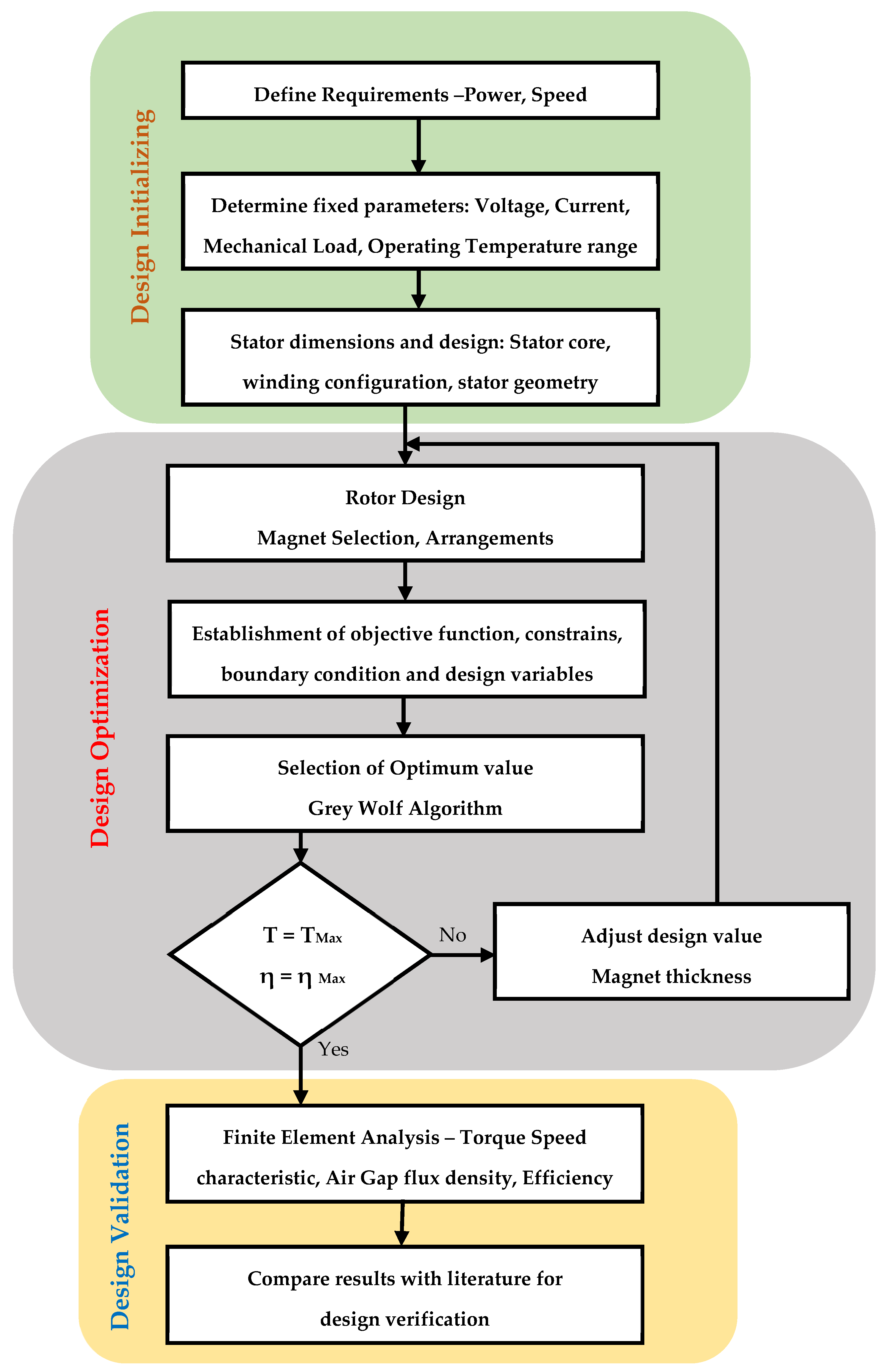
  • This research employs a Grey Wolf Optimizer (GWO) algorithm for the first time to optimize the design of a BLDC motor for irrigation applications. This approach aims to find the optimal dimensions and grade of Neodymium Iron Boron (NdFeB) magnets, leading to superior energy efficiency.
  • The design specifically caters to a 1 hp, 3000 rpm, 48 V configuration, ideal for powering centrifugal monoset pumps commonly used in irrigation. This ensures tailored performance for this prevalent irrigation system.
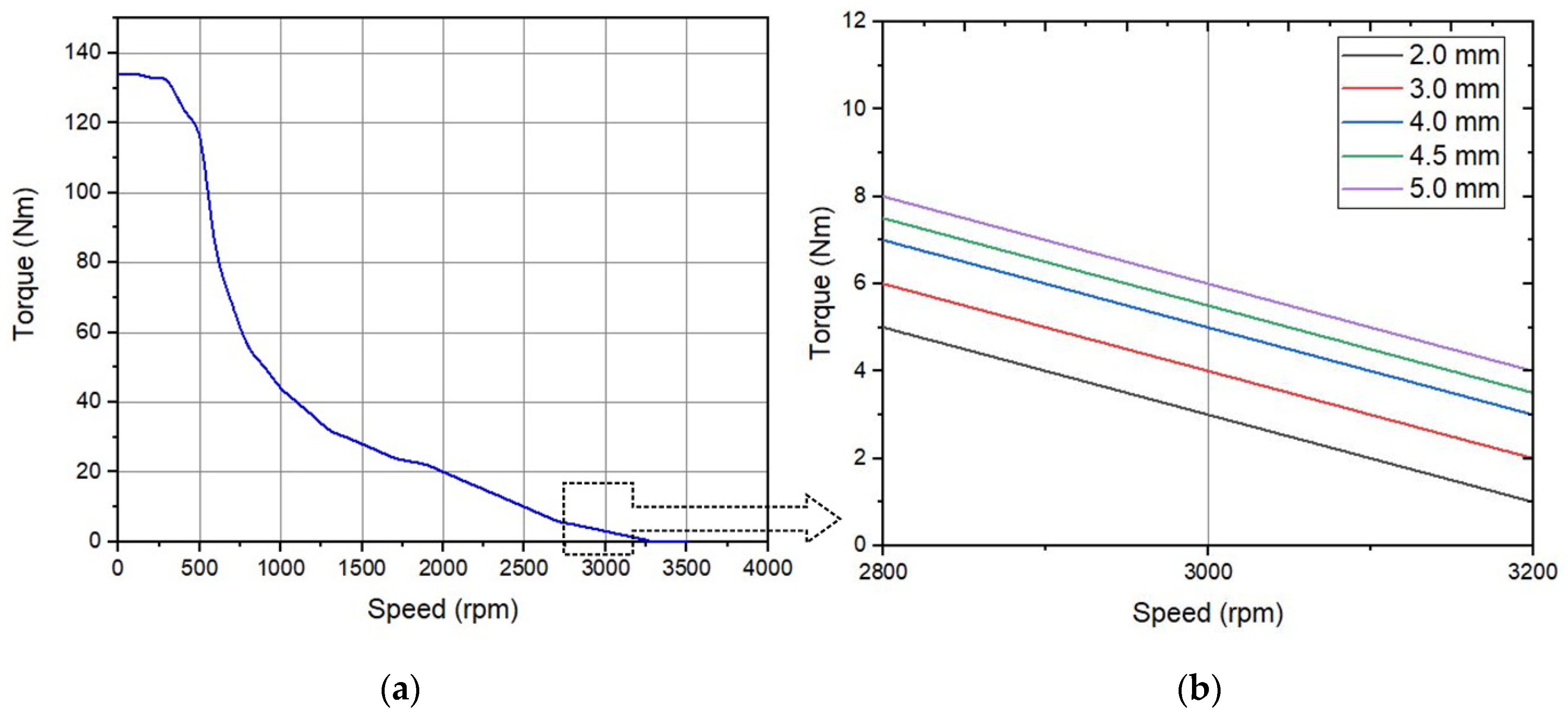
  • The research utilizes MagNet software for finite element analysis to model and evaluate the BLDC motor’s performance. This comprehensive analysis provides insights into speed, torque, flux functions, and efficiency.
  • The GWO-optimized design achieves a significant 6% increase in efficiency compared to conventional approaches. The 3D finite element analysis validates these improvements by demonstrating enhanced magnet flux linkage, reduced stator tooth flux density, and optimized rotor inertia with increased magnet thickness.
The structure of this article is outlined as follows. To begin, the introduction covers the relevant concepts of the proposed BLDC motor centrifugal monoset pump. Second, for the proposed BLDC motor structure, stator and rotor parameters are designed analytically. Third, a detailed exposition of the structure of the centrifugal monoset pump system is provided. Fourth, the finite element analysis of the BLDC motor using magnet software is presented and analyzed. Finally, the experimental testing was executed to demonstrate the energy efficiency of the designed BLDC motor centrifugal monoset pump in practical cases.

2. Design of BLDC Motor

The objective is to design a BLDC motor specifically to use as a drive in a centrifugal monoset pumping system. BLDC motors are designed to achieve up to 90% efficiency and high power density. NdFeB magnets in BLDC motors result from combining neodymium (Nd), iron (Fe), and boron (B), each with distinct densities. These magnets provide the highest magnetic field strength per unit volume among available magnets, facilitating the creation of lightweight and compact product designs [54,55]. The utilization of robust neodymium magnets and improved magnetic circuit design empowers the motor to generate a more potent electromagnetic flux, consequently decreasing electromagnetic losses. The suggested electromagnetic design necessitates a low startup voltage and minimal current consumption.
Maintaining a constant air gap length is essential for achieving high power density in motor design. High-power-density motors prioritize lightweight structures and high electromagnetic loads, optimizing power density through strategic rotor and stator configurations. Magnetic circuits design boost efficiency and reduce cogging torque [56,57]. Additionally, enhancements in no-load back EMF and phase current improve motor output power density. Motor power density hinges on factors like flux density in the air gap, ampere turns, and cooling conditions. When aiming for specific power and efficiency standards, a higher power density leads to reduced motor weight. Equation (1) establishes a relationship between output power (Pout), efficiency (η), stator inner diameter (DS), and stack length (L), revealing an inverse correlation between motor dimensions and efficiency, while the output power rises with increasing dimensions. In agriculture applications, especially in bore well pumps, the motor diameter has restrictions based on bore well size. Consequently, the diameter remains fixed, and length varies based on the power density concept in sizing the motor.
D S 2 L = P o u t η ,
The proposed motor specifications are given in Table 1. The design steps and analytical solution for the entire motor design that fits within the standard bore size of 4 inches are discussed below.

2.1. Analytical Design Procedure

An initial motor model is designed analytically. It provides an entire design, including dimensions, winding configuration, phase coil information, and rotor parameters. Equation (2) is applied to estimate the dimensions of a radial flux BLDC motor that will generate the needed torque to drive the centrifugal pump.
T = k D r 2 L
where k is a torque constant, Dr is the rotor outer diameter, and L is the stack length.
L = r D s
D s = D r / f
where Ds is the stator outer diameter, which is fixed in the case of borewell applications, r is motor aspect ratio, and f is rotor stator ratio. Equation (2) can be expressed as:
T = k r / f D r 3
Rotor dimensions based on the permanent magnet portions of a motor can be determined by relating the magnet poles, slots, and the rotor’s outside radius. Core thickness is calculated by Equation (6).
t c = π D r B g / 2 N m K s t B r
where Nm is the number of poles, Kst is the stacking factor, Br is the fixed maximum flux density of the rotor core, and Bg is the air gap flux density for NdFeB arc-type rotor magnets (Br = 1.26 T and Bg = 0.56 T).
Based on the analytical design, the parameters of the stator-side core and winding are presented in Table 2. Rotor design parameters like rotor core and magnets are listed in Table 3.
The rotor includes a 4-pole diametrically magnetized permanent magnet (PM) for mechanical stabilization during high-speed operation. The permanent magnet is securely held in place by an epoxy sleeve inserted onto the rotor during high-speed operation to withstand centrifugal stress. The motor design also incorporates various features like thrust bearing and stainless-steel housing surrounded by water to enhance performance. These additions contribute to efficient operation and thermal management of the motor.

2.2. Design Optimization Using Grey Wolf Algorithm

The GWO algorithm mimics the nature of grey wolf leadership and hunting behavior [58,59]. It utilizes four types of grey wolves: alpha (α), beta (β), delta (δ), and omega (ω), to simulate hierarchical leadership. In this model, the fittest solution is designated as the alpha (α), while the second and third best solutions are named beta (β) and delta (δ), respectively [60,61]. All other candidate solutions are considered omega (ω). The GWO algorithm operates through three main steps: tracking prey, encircling prey, and attacking prey, which are employed for optimization purposes.
During the hunt, grey wolves encircle their prey, a behavior that can be mathematically modeled using Equations (7)–(10).
D = |   C · P t P t   |
W t + 1 = P t A · D
In Equations (7) and (8), t represents the current iteration, P denotes the position vector of the prey, and W signifies the position vector of the grey wolf. D, A, and C represent coefficient vectors, and the calculation of vectors A and C is achieved with Equations (9) and (10).
A = 2 a · r 1 a
C = 2 · r 2
while ‘r1’ and ‘r2’ represent random vectors within the range [0, 1]. The hunting is led by alpha (leader), followed by beta and delta, who may occasionally join in. Delta and omega are caretakers of injured wolves within the pack. Alpha is regarded as the candidate solution possessing superior knowledge about the prey’s location [62,63]. The hunt concludes when the prey ceases its movement, prompting the grey wolves to initiate the attack.
The quantity of grey wolves corresponds to the magnet thickness; the controller assesses flux density and torque, and then calculates the resulting output energy efficiency. The design process flow of the proposed GWO-based rotor design is given in Figure 1. To implement the GWO-based BLDC rotor design, magnet thickness D is defined as a grey wolf. Therefore, (8) can be modified as follows:
D i k + 1 = D i k A · D
Thus, the fitness function of the GWO algorithm is formulated as
P d i k > P d i k 1
In this equation, ‘P’ stands for power, ‘d’ represents the duty cycle, ‘i’ denotes the current number of grey wolves, and ‘k’ signifies the number of iterations.
Implemented in MatlabR2022a, the grey wolf optimization algorithm was executed with a population size of 10 and a limit of 100 iterations. The flux function was utilized as the evaluation criterion to ascertain the most suitable thickness for the rotor magnet. The iterative process involves the updating of wolf positions based on their fitness values, gradually refining the solution space towards an optimal outcome. Through iterative refinement, the algorithm aimed to converge towards an optimal magnet thickness that maximizes the flux functions and increases the system efficiency. This approach offers a computationally efficient method for solving optimization problems, particularly in machine design where complex parameter optimization is required.

3. Centrifugal Monoset Pump

Pumps are crucial components in various sectors, including domestic, agriculture, and industry, among others. Among the different types of pumps, centrifugal pumps are particularly vital in critical applications. Ensuring the continuous availability of these mechanical components is of utmost importance. Monoblock centrifugal pumps serve residential, agricultural, industrial, and commercial settings, ensuring reliable water supply, irrigation, and fluid management in various scenarios. The performance of the bearing and impeller directly impacts the desired characteristics of a monoblock centrifugal pump.
A wide range of pumps, including submersible and monoblock pumps, are commercially available in various power ranges from 0.5 HP to 50 HP. For the purpose of this study, a specific model of a 1 hp monoblock pump was chosen, which consists of several components, such as the impeller, adaptor, main and auxiliary winding, and end cover. This particular model of pump is commonly used in domestic applications. The selection of the 1 hp monoblock pump for this case study was based on its popularity and high sales volume. To develop the design and reduce costs, the impeller, adaptor, end cover, and windings were chosen as the components for the value engineering technique implementation.
The monoblock centrifugal pump for irrigation is taken for this testing. The parameters of the monoblock centrifugal pump used to be driven by the designed motor are given in Table 4.
Typically, the BLDC motor drive shaft extends towards the pump unit, and at its end, the impeller is attached. The pump employs a mechanical sealing mechanism to ensure proper sealing. The pump efficiency is given by
η = ρ g Q H
In the given Equation (13), the symbol ρ represents the liquid density (kg/m3), g represents the acceleration due to gravity (m/s2), Q represents the flowrate (m3/s), and H represents the pump head (m).

4. Finite Element Analysis of BLDC Motor Using MagNet Software

Pumps are crucial components in various sectors, including domestic, agriculture, and industry, among others. Among the different types of pumps, centrifugal pumps are particularly vital in critical applications. Ensuring the continuous availability of these mechanical components is of utmost importance. Monoblock centrifugal pumps serve residential, agricultural, industrial, and commercial settings, ensuring reliable water supply, irrigation, and fluid management in various scenarios. The performance of the bearing and impeller directly impacts the desired characteristics of a monoblock centrifugal pump.
The development of a BLDC motor intended for agricultural applications was executed utilizing MagNet BLDC, a design software based on finite element analysis (FEA). With the rising demand for enhanced efficiency and reduced costs in electric motors, the necessity for dependable software capable of delivering precise results becomes paramount. Conventional approaches like general approximations and magnetic circuit calculations fall short in accurately forecasting the performance of contemporary electric motors.
In electric motor design, Computer-Aided Design (CAD) serves as the primary step, where Infolytica software (MagNet v7.1.1) was utilized for designing the proposed BLDC motor. Solid models with various magnet thicknesses were employed to derive the motor design, while MagNet BLDC software conducted FEA simulations to ensure accurate analysis. The software’s automated FEA solver simplified the calculation of crucial parameters such as torque, losses, and power. This approach considers intricate electromagnetic phenomena, offering valuable insights into motor performance. Consequently, designers can make informed decisions throughout the design process.
The design process for the proposed BLDC motor took into account factors such as bore diameter, magnet thickness, and all sources of loss. Initial dimensions of the motor were determined through analytical calculations. Specifications of the proposed BLDC motor are detailed in both Table 2 and Table 3. Design considerations included selecting appropriate materials for stator and rotor construction, determining the number of stator slots, and defining the number of rotor teeth. The cross-section of a BLDC motor for a centrifugal monoset pump with V4 stampings with windings and rotor magnet arrangements is given in Figure 2.
In magnet software, the crucial motor input parameters such as geometry, material properties, coil setups, and operational conditions are fed. To achieve the highest torque density, the motor design utilizes high-energy rare earth magnets, specifically NdFeB (Neodymium Iron Boron). These magnets offer exceptional magnetic properties. Among the various grades of sintered NdFeB magnets, the H, SH, EH, and UH series have gained popularity due to their ability to maintain magnetic properties even when exposed to elevated temperatures ranging from 100 to 200 degrees Celsius. In this case, SH, a NdFeB-based permanent magnet, is selected due to its remarkable thermal characteristics. To minimize core losses, a high-quality cold-roll silicon steel sheet (ST-150) is employed. This steel sheet has a thickness of 150 micrometers and is known for its excellent magnetic properties.
Following the simulations, the software produces visual representations of magnetic field strength and flux density, enabling engineers to gain insights into motor performance. Figure 3a shows the solid model of the proposed motor design and Figure 3b gives the meshed model. This information guides design enhancements, which may involve adjustments in dimensions, winding schemes, and materials. Consequently, magnet software plays a pivotal role in enhancing BLDC motor efficiency and performance, streamlining the design process, and minimizing the need for extensive physical prototyping.
The proposed BLDC design is simulated with 120° conduction. Figure 4a illustrates the distribution of flux density within the motor, where flux density is higher in the excited phase, with phase 1 having positive current, phase 2 having negative current, and phase 3 having zero current. The stator windings are energized sequentially to create a rotating magnetic field that interacts with the permanent magnets on the rotor, resulting in rotational motion. This excitation process is simulated, and the desired motor speed, direction, and torque are achieved. Figure 4b gives the flux due to the proposed rotor NdFeb magnet.

5. Discussion

The output generated by the Grey Wolf Optimization (GWO) algorithm serves as a comprehensive evaluation of the optimization process, providing valuable insights into the rotor magnet thickness solutions and convergence characteristics. Through iterative refinement, GWO aims to optimize the specified objective function magnet thickness, yielding a potential solution of magnet thickness of 4.978 mm, which represents the best-performing flux function configurations within the search space. The optimized value is rounded off to very near value of 5 mm due to manufacturing constraints. The convergence characteristics of the GWO algorithm in Figure 5 depict how the fitness function value evolves over iterations. This fitness function could incorporate parameters such as magnetic flux density, air gap flux density, and magnetic field strength. By analyzing the GWO output, Figure 5a gives convergence characteristics of GWO for Grade N35 with a fitness value of 1.45. Similarly, Figure 5b–e represent convergence characteristics for Grade N40, N45, N50, and N52, respectively, having a fitness value of 1.49, 1.39, 1.08, and 1.06. GWO sought to converge towards optimal solutions for each magnet grade; based on the comparison of the fitness value, Grade N40 provides higher fitness value across a spectrum of various NdFeB magnet grades. This optimal solution for the given rotor magnet design optimization problem facilitates further implementation steps.
Based on the GWO, in this design, magnet thickness is fixed as 5.0 mm. To validate, FEA analysis is carried out using various magnet thickness, including 2.0 mm, 3.0 mm, 4.0 mm, 4.5 mm, and 5.0 mm, to achieve air gap flux density of 0.35T.
Additionally, Figure 6 gives the FEA analysis of rotor-side flux due to NdFeB magnet thickness on the stator, Figure 6a–e represent flux values for 2.0 mm, 3.0 mm, 4.0 mm, 4.5 mm, and 5.0 mm, respectively, and Table 5 gives the analysis considering stator outer flux density (T), air gap flux density (T), and magnet flux density (T) across different magnet thicknesses.
Figure 7a–c project the stator flux in each phase. Figure 7d gives the resultant flux due to interaction of both stator and rotor fields. FEA analysis is carried out for the proposed design for magnet thickness of 5.0 mm. In the air gap, the resultant flux density is considerably high compared to conventional designs.
Figure 8a gives the air gap flux density for an electrical cycle in which peak flux density in the stator remains below 0.72 T.
The plots in Figure 9a,b give the insight variation of torque vs. speed for different magnet values. The proposed BLDC motor has an average torque of 7 Nm at the rated speed, which is sufficient to drive the impeller in the pump to deliver the rated discharge of water. The torque remains constant up to a certain speed and subsequently decreases as the speed increases.
Figure 10a shows that the proposed motor operates at maximum efficiency of 91% at the rated speed of 3000 rpm for a magnet thickness of 5 mm and N40 grade. Figure 10b gives the variation in efficiency with different grades.
The analysis demonstrates the increased efficiency at the rated speed of the proposed designed BLDC motor. By utilizing finite element analysis (FEA), the performance of the motor was accurately and precisely calculated, providing valuable insights such as flux and torque characteristics. Furthermore, the study involved a comparison of the flux characteristics of various NdFeB magnets of differing thicknesses, as depicted in Table 6.
The findings revealed significant disparities in motor torque, speed, and efficiency when utilizing magnets of the same type but with varying thicknesses, particularly at 5 mm. Table 7 highlights that certain magnets exhibited superior torque performance, notably the N40 magnet from the range of magnets with varying efficiency. Table 8 gives the comparision of various design methods and FEA results, in which the GWO method for BLDC motor rotor design gives a higher efficiency level.
Validation solely through simulation involves grey wolf optimzation for rotor parameter design, then developing a comprehensive FEA simulation model that accurately represents the BLDC motor. This model undergoes verification against theoretical principles. Next, a set of diverse validation test cases with varying magnet thickness and grades is designed to cover various scenarios and conditions. The simulation is then executed, and results are analyzed, with flux analysis conducted to discern critical factors like efficiency. It is assessed that, in addition to increased magnetic strength, the thickness of the magnet can also impact motor performance. The power losses of the fabricated BLDC motor are estimated, and it is designed to operate under rated conditions at a temperature of 120 °C. During this operating condition, the motor achieves an efficiency above 90.2%. The theoretical results obtained from calculations can be validated through measurements in FEA analysis. It is evident that the efficiency of the proposed BLDC motor increases with the constant speed operation and leads to proportional change in flow rate in the pump and squared proportional variation in the pump head. This leads to performance and efficiency increase in the BLDC motor centrifugal monoset pump set used in agriculture application.

6. Conclusions

This article introduces a unique method to optimize a BLDC motor for agricultural centrifugal monoset pumps, operating at a power rating of 1 hp and a speed rating of 3000 rpm. utilizing the Grey Wolf Optimization Algorithm to refine rotor design with diverse NdFeB magnet grades and thicknesses, the design and analysis of the motor are based on an analytical approach, focusing on the magnetic flux density, dimensions, and efficiency. Based on the Grey Wolf Optimization Algorithm analysis, it was determined that the N40 grade neodymium magnet is the optimal choice for this specific 1 hp motor design, and a thickness of 5 mm is the most suitable configuration for this magnet type. Through the utilization of finite element analysis and testing, the developed BLDC motor is thoroughly evaluated and its efficiency is 90.2%. The results obtained from the finite element analysis measurements validate the proposed design and analysis scheme, affirming its accuracy and reliability. The comprehensive analysis and validation process carried out on the proposed BLDC motor provide assurance of the motor performance and suitability for the centrifugal monoset pump. In comparison to an equivalent single-phase induction motor-driven pump, the BLDC-driven setup yields a 15% increase in both water discharge and pump head. Furthermore, the overall conversion efficiency demonstrates a 7% enhancement within the nominal operating head range and the motor pump system is energy-efficient. Future directions may entail exploring advanced materials and renewable energy integration to enhance the efficiency of BLDC motor-driven irrigation systems for sustainable agricultural practices.

Author Contributions

Conceptualization, P.R.G.K.; Methodology, R.P.A., N.R. and Y.A.; Validation, P.R.G.K., R.A. and Y.A.; Formal analysis, N.R.; Investigation, Y.A.; Writing—original draft, R.P.A.; Writing—review & editing, P.R.G.K., N.R. and R.A.; Visualization, N.R.; Funding acquisition, R.A. and Y.A. All authors have read and agreed to the published version of the manuscript.

Funding

This research was funded by Taif University, Taif, Saudi Arabia (TU-DSPP-2024-17).

Data Availability Statement

The original contributions presented in the study are included in the article, further inquiries can be directed to the corresponding authors.

Acknowledgments

The author extend their appreciation to Taif University, Saudi Arabia, for supporting this work through project number (TU-DSPP-2024-17).

Conflicts of Interest

The authors declare no conflicts of interest.

References

  1. Yalavarthi, A.; Singh, B. An Adaptive-Gain Super-Twisting Position Observer for Grid-Interfaced SRM Water Pump. IEEE Trans. Consum. Electron. 2022, 68, 366–375. [Google Scholar] [CrossRef]
  2. Vishnuram, P.; Suresh, P.; Narayanamoorthi, R.; Vijayakumar, K.; Nastasi, B. Wireless Chargers for Electric Vehicle: A Systematic Review on Converter Topologies, Environmental Assessment, and Review Policy. Energies 2023, 16, 1731. [Google Scholar] [CrossRef]
  3. Pongiannan, R.K.; Krishnamoorthy, M.; Srinivasan, S.; Chandrasekaran, M.; Bharatiraja, C.; Praveen Kumar, B.; Cherukuri, S.K.; Babu, T.S.; Alhelou, H.H. Cost-Effective Energy Conservation Techniques for Textile Spinning Mills. IEEE Access 2022, 10, 49839–49852. [Google Scholar] [CrossRef]
  4. De Souza, D.F.; da Guarda, E.L.A.; Sauer, I.L.; Tatizawa, H. Energy Efficiency Indicators for Water Pumping Systems in Multifamily Buildings. Energies 2021, 14, 7152. [Google Scholar] [CrossRef]
  5. Chen, R.; Zhao, B.; He, T.; Tu, L.; Xie, Z.; Zhong, N.; Zou, D. Study on coupling transient mixed lubrication and time-varying wear of main bearing in actual operation of low-speed diesel engine. Tribol. Int. 2024, 191, 109159. [Google Scholar] [CrossRef]
  6. Huang, Z.; Lyu, Z.; Luo, P.; Zhang, G.; Ying, W.; Chen, A.; Xiao, H. Effects of Methanol–Ammonia Blending Ratio on Performance and Emission Characteristics of a Compression Ignition Engine. J. Mar. Sci. Eng. 2023, 11, 2388. [Google Scholar] [CrossRef]
  7. Huang, Z.; Lyu, Z.; Luo, P.; Zhang, G.; Ying, W.; Chen, A.; Xiao, H. Voltage and frequency stabilization control strategy of virtual synchronous generator based on small signal model. Energy Rep. 2023, 9, 583–590. [Google Scholar] [CrossRef]
  8. Song, J.; Mingotti, A.; Zhang, J.; Peretto, L.; Wen, H. Fast iterative-interpolated DFT phasor estimator considering out-of-band interference. IEEE Trans. Instrum. Meas. 2022, 71, 9005814. [Google Scholar] [CrossRef]
  9. Song, J.; Mingotti, A.; Zhang, J.; Peretto, L.; Wen, H. Accurate Damping Factor and Frequency Estimation for Damped Real-Valued Sinusoidal Signals. IEEE Trans. Instrum. Meas. 2022, 71, 6503504. [Google Scholar] [CrossRef]
  10. Gao, Y.; Doppelbauer, M.; Ou, J.; Qu, R. Design of a double-side flux modulation permanent magnet machine for servo application. IEEE J. Emerg. Sel. Top. Power Electron. 2021, 10, 1671–1682. [Google Scholar] [CrossRef]
  11. Li, T.; Shi, H.; Bai, X.; Zhang, K.; Bin, G. Early performance degradation of ceramic bearings by a twin-driven model. Mech. Syst. Signal Process. 2023, 204, 110826. [Google Scholar] [CrossRef]
  12. Muralidharan, V.; Sugumaran, V.; Indira, V. Fault Diagnosis of Monoblock Centrifugal Pump Using SVM. Eng. Sci. Technol. Int. J. 2014, 17, 152–157. [Google Scholar] [CrossRef]
  13. Panchanathan, S.; Vishnuram, P.; Rajamanickam, N.; Bajaj, M.; Blazek, V.; Prokop, L.; Misak, S. A Comprehensive Review of the Bidirectional Converter Topologies for the Vehicle-to-Grid System. Energies 2023, 16, 2503. [Google Scholar] [CrossRef]
  14. Jang, S.M.; Cho, H.W.; Choi, S.K. Design and Analysis of a High-Speed Brushless DC Motor for Centrifugal Compressor. IEEE Trans. Magn. 2007, 43, 2573–2575. [Google Scholar] [CrossRef]
  15. Al-Faruq, H.Y.; Septanto, H. A Comparison between Six-Step and Sine-Wave Commutation Methods for Brushless Direct Current Motors. Int. J. Power Electron. Drive Syst. 2022, 13, 665. [Google Scholar] [CrossRef]
  16. Nguyen, Q.D.; Tran, V.T.; Pham, Q.D.; Giap, V.N.; Trinh, M.H. Design Brushless DC Motor Control by Using Proportional-Integral Strategy for a Smart Storage Cabinet System. Int. J. Power Electron. Drive Syst. 2023, 14, 708–718. [Google Scholar] [CrossRef]
  17. Gurgi, Z.K.; Abdalla, A.I.; Hassan, E.D. Simulation Analysis of DC Motor Based Solar Water Pumping System for Agriculture Applications in Rural Areas. Int. J. Power Electron. Drive Syst. 2023, 14, 2409–2417. [Google Scholar] [CrossRef]
  18. Paramonov, A.; Oshurbekov, S.; Kazakbaev, V.; Prakht, V.; Dmitrievskii, V. Investigation of the Effect of the Voltage Drop and Cable Length on the Success of Starting the Line-Start Permanent Magnet Motor in the Drive of a Centrifugal Pump Unit. Mathematics 2023, 11, 646. [Google Scholar] [CrossRef]
  19. Tarhan, Ü.; Selim, E.; Akın, Ö. Determination and Functional Implementation of Operating Point of a Centrifugal Pump With BLDC Motor. IEEE Can. J. Electr. Comput. Eng. 2022, 45, 105–113. [Google Scholar] [CrossRef]
  20. Pongiannan, R.K.; Tantray, S.N.; Bhat, W.I.; Ganaie, S.L.; Dewangan, O.P.; Bharatiraja, C.; Vaiyapuriappan, R. Development of BLDC Motor-Pump System for Energy Efficient Applications. In Proceedings of the Proceedings of the 3rd International Conference on I-SMAC IoT in Social, Mobile, Analytics and Cloud, I-SMAC 2019, Palladam, India, 12–14 December 2019. [Google Scholar]
  21. Haq, S.; Biswas, S.P.; Hosain, M.K.; Rahman, M.A.; Islam, M.R.; Elavarasan, R.M.; Muttaqi, K.M. A Modified PWM Scheme to Improve the Power Quality of NPC Inverter Based Solar PV Fed Induction Motor Drive for Water Pumping. IEEE Trans. Ind. Appl. 2023, 59, 3019–3030. [Google Scholar] [CrossRef]
  22. Moradi Cheshmehbeigi, H. Design and Implementation of the New Sensorless Rotor Position Estimation in Homopolar Salient-Pole Brushless DC Motor. IEEE J. Emerg. Sel. Top. Power Electron. 2022, 10, 2020–2029. [Google Scholar] [CrossRef]
  23. Smółka, K.; Firych-Nowacka, A.; Wiak, S. Comparison of the Design of 3-Pole BLDC Actuators/Motors with a Rotor Based on a Single Permanent Magnet. Sensors 2022, 22, 3759. [Google Scholar] [CrossRef] [PubMed]
  24. Mohanraj, D.; Aruldavid, R.; Verma, R.; Sathiyasekar, K.; Barnawi, A.B.; Chokkalingam, B.; Mihet-Popa, L. A Review of BLDC Motor: State of Art, Advanced Control Techniques, and Applications. IEEE Access 2022, 10, 54833–54869. [Google Scholar] [CrossRef]
  25. Shen, Y.; Liu, D.; Liang, W.; Zhang, X. Current Reconstruction of Three-Phase Voltage Source Inverters Considering Current Ripple. IEEE Trans. Transp. Electrif. 2023, 9, 1416–1427. [Google Scholar] [CrossRef]
  26. Fei, M.; Zhang, Z.; Zhao, W.; Zhang, P.; Xing, Z. Optimal power distribution control in modular power architecture using hydraulic free piston engines. Appl. Energy 2024, 358, 122540. [Google Scholar] [CrossRef]
  27. Wang, L.; Zou, T.; Cai, K.; Liu, Y. Rolling bearing fault diagnosis method based on improved residual shrinkage network. J. Braz. Soc. Mech. Sci. Eng. 2024, 46, 172. [Google Scholar] [CrossRef]
  28. Wang, H.; Han, Q.; Zhou, D. Nonlinear dynamic modeling of rotor system supported by angular contact ball bearings. Mech. Syst. Signal Process. 2017, 85, 16–40. [Google Scholar] [CrossRef]
  29. Miaofen, L.; Youmin, L.; Tianyang, W.; Fulei, C.; Zhike, P. Adaptive synchronous demodulation transform with application to analyzing multicomponent signals for machinery fault diagnostics. Mech. Syst. Signal Process. 2023, 191, 110208. [Google Scholar] [CrossRef]
  30. Bai, X.; Xu, M.; Li, Q.; Yu, L. Trajectory-battery integrated design and its application to orbital maneuvers with electric pump-fed engines. Adv. Space Res. 2022, 70, 825–841. [Google Scholar] [CrossRef]
  31. Zhang, H.; Wu, H.; Jin, H.; Li, H. High-Dynamic and Low-Cost Sensorless Control Method of High-Speed Brushless DC Motor. IEEE Trans. Ind. Inform. 2023, 19, 5576–5584. [Google Scholar] [CrossRef]
  32. Farina, S.; Firdaus, R.N.; Ahmad, M.S.; Jidin, A.; Sutikno, T. Winding Arrangement of a New Type Hollow Rotor BLDC Motor. Int. J. Power Electron. Drive Syst. 2018, 9, 933–946. [Google Scholar] [CrossRef]
  33. Khan, K.R.; Miah, M.S. Fault-Tolerant BLDC Motor-Driven Pump for Fluids with Unknown Specific Gravity: An Experimental Approach. IEEE Access 2020, 8, 30160–30173. [Google Scholar] [CrossRef]
  34. Fang, L.; Li, D.; Qu, R. Torque Improvement of Vernier Permanent Magnet Machine With Larger Rotor Pole Pairs Than Stator Teeth Number. IEEE Trans. Ind. Electron. 2023, 70, 12648–12659. [Google Scholar] [CrossRef]
  35. Zhang, J.; Chen, Y.; Gao, Y.; Wang, Z.; Peng, G. Cascade ADRC Speed Control Base on FCS-MPC for Permanent Magnet Synchronous Motor. J. Circuits Syst. Comput. 2021, 30, 2150202. [Google Scholar] [CrossRef]
  36. Zhang, J.; Zhu, D.; Jian, W.; Hu, W.; Peng, G.; Chen, Y.; Wang, Z. Fractional Order Complementary Non-singular Terminal Sliding Mode Control of PMSM Based on Neural Network. Int. J. Automot. Technol. 2024, 25, 213–224. [Google Scholar] [CrossRef]
  37. Sun, Q.; Lyu, G.; Liu, X.; Niu, F.; Gan, C. Virtual Current Compensation-Based Quasi-Sinusoidal-Wave Excitation Scheme for Switched Reluctance Motor Drives. IEEE Trans. Ind. Electron. 2023. early access. [Google Scholar] [CrossRef]
  38. Wang, H.; Sun, W.; Jiang, D.; Qu, R. A MTPA and Flux-Weakening Curve Identification Method Based on Physics-Informed Network Without Calibration. IEEE Trans. Power Electron. 2023, 38, 12370–12375. [Google Scholar] [CrossRef]
  39. Chen, J.; Xu, J.; Zhang, Y.; Zhao, J.; Hou, J.; Wang, Y. Geometrical State-Plane-based Synchronous Rectification Scheme for LLC Converter in EVs. IEEE Trans. Transp. Electrif. 2024. early access. [Google Scholar] [CrossRef]
  40. Hu, W.; Wang, T.; Chu, F. A novel Ramanujan digital twin for motor periodic fault monitoring and detection. IEEE Trans. Ind. Inform. 2023, 19, 11564–11572. [Google Scholar] [CrossRef]
  41. Toker, K.; Tosun, O.; Serteller, N.F.O.; Topuz, V. Design, Optimization and Experimental Study of Axial and Hub BLDC Motors in-Wheel Application for Light Electric Vehicles. In Proceedings of the MELECON 2022—IEEE Mediterranean Electrotechnical Conference, Palermo, Italy, 14–16 June 2022. [Google Scholar]
  42. Mohanraj, D.; Gopalakrishnan, J.; Chokkalingam, B.; Mihet-Popa, L. Critical Aspects of Electric Motor Drive Controllers and Mitigation of Torque Ripple—Review. IEEE Access 2022, 10, 73635–73674. [Google Scholar] [CrossRef]
  43. Azhari, B.; Irasari, P.; Widianto, P. Design and Simulation of 5kw Bldc Motor with Half-Buried Permanent Magnets Using an Existing Stator Body. Int. J. Power Electron. Drive Syst. 2021, 12, 2030–2043. [Google Scholar] [CrossRef]
  44. Du, J.; Li, C.; Zhao, J.; Ren, H.; Zhang, K.; Song, X.; Chen, L.; Yu, S.; Mi, Y. Investigation of Eddy Current Loss and Structure Design with Magnetic-Thermal Coupling for Toothless BLDC High-Speed PM Motor. Machines 2022, 10, 118. [Google Scholar] [CrossRef]
  45. Lee, H.Y.; Yoon, S.Y.; Kwon, S.O.; Shin, J.Y.; Park, S.H.; Lim, M.S. A Study on a Slotless Brushless Dc Motor with Toroidal Winding. Processes 2021, 9, 1881. [Google Scholar] [CrossRef]
  46. Hussain, M.; Ulasyar, A.; Zad, H.S.; Khattak, A.; Nisar, S.; Imran, K. Design and Analysis of a Dual Rotor Multiphase Brushless DC Motor for Its Application in Electric Vehicles. Eng. Technol. Appl. Sci. Res. 2021, 11, 7846–7852. [Google Scholar] [CrossRef]
  47. Qu, R.; Lipo, T.A. Dual-Rotor, Radial-Flux, Toroidally Wound, Permanent-Magnet Machines. IEEE Trans. Ind. Appl. 2003, 39, 1665–1673. [Google Scholar] [CrossRef]
  48. Elakkia, E.; Anita, S.; Girish Ganesan, R.; Saikiran, S. Design and modelling of bldc motor for automotive applications. Int. J. Electr. Electron. Eng. Telecommun. 2015, 1, 42–48. [Google Scholar]
  49. Kumar, N.S.; Chandrasekaran, G.; Thangavel, J.; Vanchinathan, K.; Gnanavel, C.; Priyadarshi, N.; Bhaskar, M.S.; Hussien, M.G.; El-Sousy, F.F.M.; Ali, M.M. A Novel Design Methodology and Numerical Simulation of BLDC Motor for Power Loss Reduction. Appl. Sci. 2022, 12, 10596. [Google Scholar] [CrossRef]
  50. Upadhyay, P.R.; Rajagopal, K.R. FE Analysis and Computer-Aided Design of a Sandwiched Axial-Flux Permanent Magnet Brushless DC Motor. IEEE Trans. Magn. 2006, 42, 3401–3403. [Google Scholar] [CrossRef]
  51. He, C.; Wu, T. Permanent Magnet Brushless Dc Motor and Mechanical Structure Design for the Electric Impact Wrench System. Energies 2018, 11, 1360. [Google Scholar] [CrossRef]
  52. Upadhyay, P.R.; Rajagopal, K.R. FE Analysis and CAD of Radial-Flux Surface Mounted Permanent Magnet Brushless DC Motors. IEEE Trans. Magn. 2005, 41, 3952–3954. [Google Scholar] [CrossRef]
  53. Indian Standard Number IS 9079: 2018; Monoset Pumps for Clear, Cold Water for Agricultural and Water Supply Purposes—Specification (Third Revision). Bureau of Indian Standards (BIS): New Delhi, India, 2018; Reviewed in 2022.
  54. Sheela, A.; Suresh, M.; Shankar, V.G.; Panchal, H.; Priya, V.; Atshaya, M.; Sadasivuni, K.K.; Dharaskar, S. FEA Based Analysis and Design of PMSM for Electric Vehicle Applications Using MagNet Software. Int. J. Ambient. Energy 2022, 43, 2742–2747. [Google Scholar] [CrossRef]
  55. Bhuvaneswari, S.; Sivaraman, P.; Anitha, N.; Matheswaran, A. Optimized Design of Permanent Magnet Brushless DC Motor for Ceiling Fan Applications. Mater. Today Proc. 2021, 45, 1081–1086. [Google Scholar] [CrossRef]
  56. Kumpanya, D.; Thaiparnat, S.; Puangdownreong, D. Parameter Identification of BLDC Motor Model Via Metaheuristic Optimization Techniques. Procedia Manuf. 2015, 4, 322–327. [Google Scholar] [CrossRef]
  57. Tosun, O.; Serteller, N.F.O. The Design of the Outer-Rotor Brushless DC Motor and an Investigation of Motor Axial-Length-to-Pole-Pitch Ratio. Sustainability 2022, 14, 12743. [Google Scholar] [CrossRef]
  58. Mirjalili, S.; Mirjalili, S.M.; Lewis, A. Grey Wolf Optimizer. Adv. Eng. Softw. 2014, 69, 46–61. [Google Scholar] [CrossRef]
  59. Gundogdu, H.; Demirci, A.; Tercan, S.M.; Cali, U. A Novel Improved Grey Wolf Algorithm Based Global Maximum Power Point Tracker Method Considering Partial Shading. IEEE Access 2024, 12, 6148–6159. [Google Scholar] [CrossRef]
  60. Toren, M. Comparatıve Analysis of the Magnet Effects on the Permanent Magnet BLDC Motor Performance Used in Electric Vehicles. Electr. Eng. 2022, 104, 3411–3423. [Google Scholar] [CrossRef]
  61. Li, X.; Wang, Z.; Yang, C.; Bozkurt, A. An advanced framework for net electricity consumption prediction: Incorporating novel machine learning models and optimization algorithms. Energy 2024, 296, 131259. [Google Scholar] [CrossRef]
  62. Tang, Z.H.; Chen, Y.T.; Liou, Y.K.; Liang, R.H. Axial Magnetic Force Analysis and Optimized Design for Single-Phase BLDC Slim Fan Motors. IEEE Trans. Ind. Electron. 2021, 68, 6840–6848. [Google Scholar] [CrossRef]
  63. Pandey, M.K.; Tripathi, A.; Dwivedi, B. FEA of a High Efficiency Brushless DC Motor Design. Int. J. Appl. Eng. Res. 2017, 12, 11417–11423. [Google Scholar]
Figure 1. Flowchart of GWO-based BLDC motor design.
Energies 17 02280 g001
Figure 2. Cross-section of a BLDC motor with stator V4 stamping and rotor magnets.
Energies 17 02280 g002
Figure 3. Proposed design of BLDC motor FEA: (a) solid model; (b) mesh model.
Energies 17 02280 g003
Figure 4. BLDC motor FEA: (a) flux density distribution within the motor; (b) flux due to rotor NdFeB magnet on stator side.
Energies 17 02280 g004
Figure 5. Convergence characteristics of GWO for (a) Grade N35, (b) Grade N40, (c) Grade N45, (d) Grade N50, (e) Grade N52.
Energies 17 02280 g005
Figure 6. Rotor-side flux due to NdFeB magnet thickness on stator: (a) Design 1—2.0 mm, (b) Design 2—3.0 mm, (c) Design 3—4.0 mm, (d) Design 4—4.5 mm, (e) Design 5—5.0 mm.
Energies 17 02280 g006
Figure 7. BLDC motor FEA: (a) stator flux phase A, (a) stator flux phase A, (b) stator flux phase B, (c) stator flux phase C, (d) flux due to interaction of both stator and rotor fields.
Energies 17 02280 g007
Figure 8. BLDC motor: (a) air gap flux density vs. electric degree, (b) air gap flux density variation for different magnet thickness.
Energies 17 02280 g008
Figure 9. BLDC motor: (a) torque vs. speed, (b) torque vs. speed for different magnet values.
Energies 17 02280 g009
Figure 10. BLDC motor FEA: (a) variation in efficiency with respect to speed, (b) variation in efficiency with respect to speed for different magnet values.
Energies 17 02280 g010
Table 1. Motor specification.
ParameterValues
Motor power1 hp
Voltage48 V DC
Current18A
Poles4 pole
Casing304 strainless steel, IP68
Stamping SizeV4 water filled
Table 2. Design parameters of stator core and windings.
ParameterValues
Stator outer diameter (Ds)90 mm
Rotor outer diameter (Dr)47 mm
stack length (L)65 mm
Stator stacking factor 0.95
Slot area82.1 mm2
windingdouble layer winding
number of conductors per slot50
slots per pole per phase2
coil span5
Angular slot pitch30 electrical
Stator outer diameter (Ds)90 mm
Rotor outer diameter (Dr)47 mm
Table 3. Design parameters of rotor core and magnet.
ParameterValues
Air gap0.5 mm
Rotor stacking factor 0.95
Pole arc radius38
Magnet Thickness2.0 mm/3.0 mm/4.0 mm/4.5 mm/5.0 mm
Magnet width39 mm
Magnetic materialNeodymium Iron Boron (NdFeB)
NdFeB magnetic gradeN35/N40/N45/N50/N52
Table 4. Monoblock centrifugal pump specifications.
ParameterValues
Rotational speed3000 rpm
Power1 hp
Head 25 m
Discharge900 lpm
Static suction lift 6 m
Table 5. Flux values corresponding to magnet thickness.
Magnet ThicknessStator Outer Flux Density (T)Air Gap Flux Density (T)Magnet Flux Density (T)
Design 12.0 mm1.380.570.63
Design 23.0 mm1.490.620.69
Design 34.0 mm1.580.660.74
Design 44.5 mm1.670.700.78
Design 55.0 mm1.730.730.81
Table 6. Comparison of flux values corresponding to magnet thickness.
Magnet
Thickness
Stator Outer Flux
Density (T)
Air Gap Flux
Density (T)
Magnet Flux
Density (T)
TheoreticalUsing
FEA
TheoreticalUsing
FEA
TheoreticalUsing FEA
2.0 mm1.401.380.600.570.660.63
3.0 mm1.521.490.650.620.720.69
4.0 mm1.601.580.690.660.760.74
4.5 mm1.691.670.730.700.810.78
5.0 mm1.751.730.750.730.830.81
Table 7. Efficiency values corresponding to magnet types.
Magnet GradeEfficiency Value (%)
TheoreticalUsing GWOUsing FEA
N3589.989.689.5
N4091.090.890.2
N4590.189.689.0
N5088.988.488.4
N5286.385.985.7
Table 8. Comparison of FEA with various optimized BLDC motor designs.
Design MethodPower
(W)
Speed
(rpm)
Torque
(Nm)
Magnet Type Efficiency
(%)
Mathematical model-based FEA [60]110030008.5Fe85.37
L/τ optimization-based FEA [61]55015003.87XG196/9689.80
GWO Method based FEA74630007N4090.20
Disclaimer/Publisher’s Note: The statements, opinions and data contained in all publications are solely those of the individual author(s) and contributor(s) and not of MDPI and/or the editor(s). MDPI and/or the editor(s) disclaim responsibility for any injury to people or property resulting from any ideas, methods, instructions or products referred to in the content.

