
Non-Integrated and Integrated On-Board Battery Chargers (iOBCs) for Electric Vehicles (EVs): A Critical Review

1
School of Engineering, Lancaster University, Lancaster LA1 4YW, UK
2
School of Engineering, Faculty of Engineering and Digital Technologies, University of Bradford, Bradford BD7 1DP, UK
*
Author to whom correspondence should be addressed.
Energies 2024, 17(10), 2285; https://doi.org/10.3390/en17102285
Submission received: 14 March 2024
/
Revised: 14 April 2024
/
Accepted: 7 May 2024
/
Published: 9 May 2024
(This article belongs to the Section D2: Electrochem: Batteries, Fuel Cells, Capacitors)
Abstract
:The rising Greenhouse Gas (GHG) emissions stemming from the extensive use of automobiles across the globe represent a critical environmental challenge, contributing significantly to phenomena such as global warming and the deterioration of air quality. To address these challenges, there is a critical need for research and development in electric vehicles (EVs) and their associated charging infrastructure, including off-board and on-board chargers (OBCs). This paper aims to bridge the gaps in existing review literature by offering a comprehensive review of both integrated and non-integrated OBCs for EVs, based on the authors’ knowledge at the time of writing. The paper begins by outlining trends in the EV market, including voltage levels, power ratings, and relevant standards. It then provides a detailed analysis of two-level and multi-level power converter topologies, covering AC-DC power factor correction (PFC) and isolated DC-DC topologies. Subsequently, it discusses single-stage and two-stage non-integrated OBC solutions. Additionally, various categories of integrated OBCs (iOBCs) are explored, accompanied by relevant examples. The paper also includes comparison tables containing technical specifications and key characteristics for reference and analysis.
1. Introduction
The escalating levels of Greenhouse Gas (GHG) emissions, primarily stemming from the combustion of fossil fuels in a vast array of vehicles worldwide (including motorcycles, cars, trucks, trains, buses, planes, ships, etc.), present significant threats by contributing to global warming and compromising air quality. The transport sector generates a considerable amount of these emissions, especially road transport, accounting for 95% of the total GHGs [1]. Electric vehicles (EVs) have emerged as a promising alternative to traditional fossil-fuel-powered cars, attracting attention due to their ability to reduce GHG emissions significantly. However, it is commonly known that with a fossil-fuel-based power generation system, EVs can still contribute to GHG production and, therefore, cannot be regarded as purely environmentally friendly. As a result, renewable energy sources (RESs), such as photovoltaic (PV), can be integrated into the EV charging infrastructure to improve the sustainability of the transportation system. It is reported that EVs can achieve up to 72% when powered by conventional energy sources and up to 97% in GHGs when utilizing RESs [2,3]. The increasing adoption, followed by the rise in EV sales, have fueled research and development efforts aimed at creating high-efficiency and reliable EV charging solutions.
EV chargers can be categorized based on their location (inside or outside the EV) and power rating into on-board and off-board (stand-alone) chargers [4,5]. An off-board battery charger is typically designed for high power flow, supporting DC fast and ultra-fast charging, and is situated outside the EV. However, they suffer from inflexibility regarding charging locations and typically incur higher costs for the installation of their battery management system (BMS) [4]. Conversely, the on-board battery chargers (OBCs) are installed inside the EV and facilitate low-power slow AC charging [6]. They are indispensable EV components, enabling the charging wherever a wall outlet is available and are appreciated for their lightweight construction, high power density, and efficiency [7,8]. As shown in Figure 1, the OBC comprises two power conversion stages. The first stage is the AC-DC conversion, which transforms the single-phase or three-phase AC grid voltage into a DC voltage with low total harmonic distortion (THD) and a high power factor (PF) [6]. Various two-level and multi-level PFCs have been used in high-power OBCs, including three-phase boost-type (also known as full-bridge (FB)) [9], totem-pole (TP) converter [6,7,10,11], and multi-level topologies (Vienna rectifier [12,13], neutral-point-clamped (NPC) converter [14,15,16,17], flying-capacitor (FC) topology [18,19,20,21,22], and modular multi-level converters [23,24,25]). The second stage involves an isolated DC-DC converter, which regulates the input DC voltage concerning the HV battery voltage and current profile. The most common isolated DC-DC converter topologies are dual-active-bridge (DAB) converter [26,27] and resonant DAB converter [28,29,30].
However, due to the considerable number of components involved, the two-stage power conversion approach is less favored for OBCs [6]. To address the limitations of two-stage chargers, single-stage OBCs have been developed, merging the functionalities of the AC-DC and DC-DC converters. This integration can lead to more compact and cost-effective solutions by eliminating the need for bulky DC-link capacitors. However, such designs often come with increased complexity in both design and control.
The power electronic converters employed In single-stage or two-stage charger configurations must target specific key performance indicators, including high efficiency, high power density, reliability, and cost-effectiveness [31]. They can provide either unidirectional or bidirectional power flows. While bidirectional power flow adds complexity and power losses, it enables functionalities like grid-to-vehicle (G2V), vehicle-to-grid (V2G), vehicle-to-vehicle (V2V), vehicle-to-home (V2H), and vehicle-to-load (V2L) [32].
To overcome size and cost constraints while achieving higher power density, eVs are increasingly adopting integrated OBCs [33]. The EV propulsion system, comprising the motor and the traction inverter (also known as the motor drive), encompasses all the essential components of a standard OBC system and can, thus, be integrated into it [34]. Additionally, the auxiliary power module (APM), serving as an intermediate isolated DC-DC converter between the HV propulsion battery and the low-voltage (LV) battery, can be integrated into the DC-DC stage of the OBC [35]. Another approach to saving space inside the EV involves incorporating wireless charging functionality into the OBC [35]. Accordingly, three types of integration have been defined: propulsion system integrated OBC (iOBC), APM iOBC, and wireless iOBC. In propulsion system iOBCs, the DC-AC traction inverter can serve as the AC-DC PFC rectifier in the OBC, while the motor windings can be reconfigured and used as the grid-side filter inductors or an inductor in the DC-DC converter. These systems are subdivided into six categories based on the components of the propulsion system utilized during charging, which include multi-winding (multi-phase) propulsion systems [36,37,38,39,40,41,42,43,44,45,46,47,48,49], access to the motor’s neutral point [50,51,52], reconfiguration of motor windings [53], split motor windings [4,54,55,56,57,58,59,60,61,62], add-on interface systems [63,64], and traction inverter [65,66,67,68,69,70,71,72,73,74,75] iOBCs. In the first five categories, both the traction inverter and electric motor (e.g., switched-reluctance motor (SRM), permanent magnet synchronous machine (PMSM), induction machine (IM)) windings are integrated into the OBC. In the sixth category, only the traction inverter is integrated into the charger.
While integrating different units into the charger can optimize component utilization and enhance overall system efficiency, it may lead to thermal management challenges [33]. A modular approach can aid in better thermal management by distributing heat across multiple modules [24,25]. Additionally, torque production during charging, voltage ripple, and second-harmonic ripples are other challenges requiring careful consideration during the integration of other units into the OBC [6].
Several recent review articles have delved into both integrated and non-integrated on-board chargers (OBCs), as outlined in Table 1, underscoring their significant contributions. Wired and wireless on-board and off-board battery chargers have been explored in [1]. Additionally, authors in [4,6] have provided reviews on non-integrated bidirectional single-stage and two-stage OBCs. Propulsion system integrated OBCs have been scrutinized in [33,34,75,76,77]. However, many of these papers tend to focus solely on either integrated or non-integrated OBC solutions, often lacking in-depth technical specifications. The study in [35] also encompasses only high-power (>7.4 kW) integrated and non-integrated OBCs.
The aim of this paper is to address the gaps found in previously published literature reviews. To accomplish this goal, the paper begins with a comprehensive examination of power electronic converter topologies used in non-integrated OBCs. It then explores discussions on single-stage and two-stage OBC solutions. Additionally, the paper explains various types of iOBCs, incorporating examples sourced from the literature. Furthermore, it provides detailed technical specifications and key characteristics of different topologies, including OBC power rating, HV battery voltage level, converter topology, switching frequency, power density, efficiency, bidirectionality, and component count, among others, presented in comparison tables.
The remainder of this paper is structured as follows: Section 2 delves into trends in EV sales, voltage levels, power ratings, and relevant standards. In Section 3, high-efficiency power electronics converters for the AC-DC power factor correction (PFC) and isolated DC-DC conversion stages are discussed. Following this, single-stage and two-stage non-integrated OBC solutions are provided. Section 4 encompasses various types of iOBCs. Finally, Section 5 presents the conclusions drawn from our discussions.
2. Trends in EV Sales, Voltage Levels, Power Ratings, and Relevant Standards
The rise in EV sales has been consistent in recent years, attributed to ongoing incentives, the introduction of new models, and increasing consumer interest. The Global EV Outlook emphasized the substantial impact of the COVID-19 pandemic on the global EV market, with a one-third decrease in new car registrations observed in the early part of 2020 compared to the previous year [2,3]. Despite this overall decline in EV sales, their registrations surged by as much as 70%, reaching a record of 3 million new registrations in 2020, signifying a 4.6% annual growth. The market is primarily dominated by China, Europe, and the U.S., with Europe leading at 1.4 million new registrations, followed by China at 1.2 million, and the United States at 295,000. Global EV sales surpassed 16.5 million units by 2021, and annual sales are projected to increase to 20.6 million by 2025 from the 6.6 million achieved in 2021. By 2030, eVs are expected to represent approximately 42%, 27%, and 48% of light-duty vehicles in Europe, the United States, and China, respectively. The share of EV sales is forecasted to reach 80% by 2040, as shown in Figure 2. To meet the EV market goals outlined by the Global EV Outlook, expanding the charging infrastructure and implementing relevant standards are crucial [2].
EV charging can occur in two forms: AC and DC voltage charging, each with different power levels. AC charging is typically categorized into Level 1 and Level 2 charging for OBCs [77]. AC single-phase charging utilizes a single-phase AC low-power supply for EV charging and is often employed in slow charging scenarios. This method involves multi-stage power conversions, such as AC-DC and DC-DC conversions, resulting in low-voltage ripples and a relatively high power rating [5]. On the other hand, AC three-phase charging employs a three-phase AC power supply, allowing for higher power delivery compared to single-phase charging. This topology is frequently utilized in commercial and public charging stations, facilitating faster charging rates [78]. In the DC charging topology, AC power sourced from the grid is initially converted to DC power using an external rectifier. This rectifier transforms the AC power to DC, which is then supplied directly to the EV battery. Compared to AC charging, DC charging is particularly suitable for public fast-charging stations and long-distance travel, as it provides faster charging rates. This topology commonly employs high-power chargers, capable of delivering power levels ranging from tens to hundreds of kilowatts. DC charging is categorized as Level 3 and ultra-fast charging, necessitating off-board chargers for implementation.
AC and DC charging levels, along with their specifications in terms of power level, supplied voltage, charger location, charging time, etc., are outlined in the following sections and summarized in Table 2.
Level 1: Level 1 charging is the slowest option and supports the lowest power level. A Level 1 AC charger typically operates with a single-phase input voltage of 120 Vac/230 Vac and delivers approximately 3.7 kW of power. The connection is often made using a standard J1772 connector into the EV AC port [79]. While Level 1 chargers are low-cost, the power they provide is usually insufficient for overnight charging of eVs [77].
Level 2: Level 2 AC chargers include both single-phase and three-phase grid connections, typically operating with an input voltage of 208 Vac or 240 Vac. While in the US, Level 2 charging connectors are either the SAEJ1772 Type 1 or the proprietary Tesla plug; in Europe, the IEC 62196-2 Type 2 plug is used for Level 2 AC charging [80]. Most eVs available on the market support Level 2 charging, with power levels ranging from 3.7 to 22 kW [80,81]. The choice of power level depends largely on the trade-off between charging time and cost of the converters. Currently, 6.6 kW is widely used, allowing a 60 kWh battery to charge from 20% to 80% in approximately 5.5 h [82]. With Level 2 charging, most commercial eVs can achieve a full overnight charge.
Level 3: The limitations of on-board Level 1 and Level 2 AC chargers, including their restricted power ratings and longer charging durations, have prompted the development of Level 3 DC fast chargers. These advanced chargers can manage power levels ranging from 50 kW to 300 kW and effectively charge existing EV batteries within 30 minutes. In the US, Level 3 DC charger connectors comprise CCS combo 1, CHAdeMo, and the Tesla Supercharger; while in Europe, CCS combo 3, CHAdeMo, and the Tesla Supercharger are utilized.
Ultra-fast DC chargers: To further alleviate the range anxiety experienced by EV drivers and enhance competitiveness with traditional IC engine-based refueling processes, DC ultra-fast charging has emerged as a promising solution. This method aims to fully charge EV batteries within 10 minutes, typically rated at power levels of 400 kW or higher [83]. However, the significant power flow between the grid and EV poses challenges and necessitates further research in some areas.
As an electronic sub-assembly (ESA), the OBC must adhere to specific regulatory standards to ensure compliance with aspects such as grid stability, safety, and interoperability [84]. Various standardization bodies contributing to the development of regional and international norms play a crucial role in this process, including the Combined Charging System (CCS) in Europe, the CHAdeMO Association in Japan, the North American Charging Standard (NACS), Nippon Electric Company (NEC), the Society of Automotive Engineers (SAE), the International Electrochemical Council (IEC), Guobiao Standards (GB), Underwriters Laboratories (UL), Institute of Electrical and Electronic Engineers (IEEE), and the International Organization for Standardization (ISO). These organizations contribute to the development of both regional and international norms [34]. Table 3 provides a summary of the standards required in the research and development of an OBC.
3. On-Board Battery Chargers (OBCs)
OBCs are primarily classified into two categories: (i) integrated and (ii) non-integrated configurations, determined by their connections to the propulsion system, APM, and wireless charging unit. Non-integrated OBCs function as independent units, simplifying design and control processes. However, this setup may introduce redundant components, leading to increased power losses and elevated costs. Conversely, integrated OBCs (iOBCs) optimize the use of charger components, boosting power density and system efficiency [6]. The EV’s propulsion system, comprising the motor and the traction inverter, embodies the essential elements of a conventional OBC system and can be integrated seamlessly [34]. Additionally, the APM unit, serving as a DC-DC converter between the HV and LV batteries, can be incorporated into the OBC’s DC-DC stage [35]. Some designs even integrate wireless charging functionality within the OBC to conserve space inside the EV [35]. Based on these integration approaches, three specific types of integrated OBCs are recognized: propulsion system iOBC, APM iOBC, and wireless iOBC. Both integrated and non-integrated OBCs can be further categorized into multiple types, as illustrated in Figure 3 and detailed in the subsequent discussion [35].
3.1. Non-Integrated OBCs
A non-integrated OBC serves as a distinct component within the EV, facilitating the connection of the charging input and supplying output power at the desired level to the HV propulsion battery [6]. Based on the number of power conversion stages, non-integrated OBCs can be divided into single-stage or two-stage topologies, as shown in Figure 3.
Two-stage non-integrated OBCs typically consist of an electromagnetic interference (EMI) filter, an AC-DC power factor correction (PFC) unit, and a DC link, followed by a galvanically isolated DC-DC converter, as illustrated in Figure 4a. Alternatively, in single-stage OBCs, the AC voltage can be rectified directly and converted to the necessary high-frequency battery voltage by consolidating the functionalities of the AC-DC PFC and the isolated DC-DC converters, as shown in Figure 4b. As a result, bulky DC-link capacitors can be avoided, power density is improved, and the cost is reduced. However, these benefits come at the expense of a more intricate design and control [31].
The following subsections present potential candidates for the sub-systems of two-stage non-integrated OBCs, namely the AC-DC and DC-DC power converters. Following this, a review of various two-stage and single-stage non-integrated OBC solutions found in the literature is provided.
3.1.1. Two-Stage Non-Integrated OBCs
AC-DC PFC Converter Topologies for Two-Stage Non-Integrated OBCs
Conventional AC-DC rectifiers interfacing the AC grid can lead to voltage drop, harmonic injection, and poor power factor and power quality caused by flat topping at the AC grid [95]. Therefore, a PFC AC-DC rectifier is utilized in EV applications to deal with these issues. Various two-level and multi-level PFCs have been implemented in high-power OBCs. Examples include three-phase boost-type PFC, totem-pole (TP) converter, and multi-level topologies [6,7,10,11,96].
A two-level three-phase boost-type PFC, which is also referred to as three-phase full-bridge PFC, is shown in Figure 5a [96]. Low efficiency under partial loads, harmonic distortion, and heat dissipation characteristics are the main concerns that should be taken into consideration during design, implementation, and control of this topology [6]. The bridgeless totem-pole PFC illustrated in Figure 5b has emerged as a preferred option in numerous OBCs, primarily because of its bidirectional power flow capability and decreased conduction losses facilitated by synchronous rectification [6,7]. It comprises a low-frequency and a high-frequency switching leg functioning as a boost converter and the rectifier, respectively [10]. Its variants, such as two- and three-channel interleaved totem-pole PFCs, are shown in Figure 5c,d. These variants have the capability to diminish output voltage ripple and enhance system efficiency [11].
To minimize dv/dt rate and distributed losses, in addition to improving reactive power injection while ensuring a favorable THD value, multi-level PFCs are frequently employed in OBCs. Multi-level topologies include the Vienna rectifier [12,13], neutral-point-clamped (NPC) converter [14,15,16,17], flying-capacitor (FC) topology [18,19,20,21,22], and modular multi-level converters [23,24,25].
Six additional switches are added to the full-bridge PFC converter shown in Figure 5a to construct the three-level Vienna rectifier (also known as T-type boost PFC) shown in Figure 6a. This converter offers the lowest conduction loss as only one power switch is used over a significant portion of the switching time [8]. Moreover, simpler control and gate driver circuits are required compared to other multi-level topologies [4]. While this topology can achieve efficiencies exceeding 99% for switching frequencies below 100 kHz [97], it encounters significant switching losses due to the requirement for a voltage blocking capability suitable for the entire DC-link voltage across power switches. This issue can be addressed by employing a neutral-point-clamped (NPC) converter. Conventional passive-clamped NPC converters encounter more conduction losses [14,15,16]. To address this concern, the active-neutral-point-clamped (ANPC) converter depicted in Figure 6b is introduced to mitigate forward conduction losses in the diode. However, this solution entails increased cost implications [17]. It is worth mentioning that an additional leg is required for balancing the capacitor voltage of a three-level converter in case the applied modulation scheme cannot maintain balance [98].
Conventionally employed in medium-voltage power electronics, the flying capacitor (FC) converter topology shown in Figure 6c has recently showcased high efficiency for low-voltage grid-tied applications [18]. This is attributed to their reduced semiconductor count compared to the ANPC topology and modular structure [18,19,20,21,22,99]. A notable drawback of these configurations is the need for pre-charge circuits. Moreover, the voltages across FCs may become unbalanced during transient conditions. Consequently, voltage stresses may surpass the nominal value [22].
The power level and reliability of the AC-DC PFC stage can be further increased using the modular multi-level (MMC) converter shown in Figure 6d. Nevertheless, MMC topologies often suffer from reduced efficiency resulting from switching and inductor losses [23]. Furthermore, the decrease in EMI filter components necessitates the use of a large capacitor.
DC-DC Converter Topologies for Two-Stage Non-Integrated OBCs
In the non-integrated two-stage OBC shown in Figure 4a, a DC-DC power stage is employed to regulate the DC-link voltage in accordance with the charging profile of the HV battery [100]. This component plays a crucial role in providing galvanic isolation between the HV battery pack and the AC grid, a requirement specified by the UL 2202 and IEC 60950 standards [101]. Figure 7 illustrates the commonly employed isolated bidirectional DC-DC converter topologies in OBCs, including the dual-active-bridge (DAB) converter [26,27] and resonant DAB converters (e.g., LLC, CLLC, and LCL-T) [28,29,30].
The DAB topology comprises full-bridge (FB) topologies on both the primary and secondary sides, interconnected by a high-frequency transformer (HFT), as depicted in Figure 7a. To enhance the leakage inductance of the transformer, a supplementary series-connected inductor can also be added to the topology [6]. The DAB converter is distinguished by its high efficiency and power density, bidirectionality, inherent soft switching, galvanic isolation, as well as wide spectrum of voltage transfer ratios [26,27]. However, effectively managing DC bias poses a significant challenge in DAB topologies. To mitigate this issue, a low-voltage DC blocking capacitor can be connected in series with the transformer winding [102,103]. This solution, however, comes at the expense of sacrificing power density [104].
Several variants of DAB converter topologies have been introduced in the literature, including two-level and multi-level configurations. Examples include the two-level series-input–series-output (SISO) DAB converter [98], three-level NPC and ANPC DAB topologies [105,106,107], three-level DAB converter with DC blocking capacitors, and three-level three-phase DAB converter [103], among others [103,105,106,107].
Resonant DAB converters are widely used EV applications. They achieve inherent zero-current switching (ZCS) and zero-voltage switching (ZVS) across the entire load range. In contrast to the DAB, the resonant DAB converter operates with a variable switching frequency, leading to increased switching and transformer losses [107,108]. Depending on the number of reactive elements and their connections, various variants of resonant DAB converters, such as CLLC, LCL-T, and LLC [109,110,111,112,113,114,115,116], are developed. Examples of two-level and multi-level variants DAB and resonant DAB converters are shown in Figure 8, with their technical specifications listed in Table 4 and Table 5.
Two-Stage Non-Integrated OBC Solutions
Examples of the most recent high-efficiency and high-power-density two-stage non-integrated OBC solutions are reviewed here, with their key characteristics summarized in Table 6.
A two-stage OBC rated at 6.6 kW is presented in [120], featuring a 300 kHz two-channel interleaved totem-pole PFC and a 500 kHz operating CLLC resonant converter for the first and the second power stages, respectively (see Figure 9a). This topology operates at a power density of 2.3 kW/L, achieving a maximum efficiency of 96.2%. To increase the power density, the series resonant inductors on the primary and secondary sides are combined with the HFT.
A similar two-stage OBC with a higher power density of 3.8 kW/L is presented in [10] (see Figure 9b). In [121], the authors have developed another 6.6 kW two-stage OBC with a 67 kHz totem-pole PFC and a 148~300 kHz CLLC resonant converter. However, unlike the prior design in [10], the totem-pole PFC in this configuration is not interleaved. The system described demonstrates a power density of 3.2 kW/L with an efficiency of 97%.
A 11 kW two-stage topology is presented in [100], in which a 350 kHz four-channel interleaved totem-pole PFC is used at the single-phase grid side and a 500 kHz three-phase CLLC resonant converter with a primary delta connection is used at the HV battery side (see Figure 9c). To reduce the common-mode noise, Return Path Windings are added to the primary side of the PFC stage. To reduce the size, these windings are integrated with the coupled inductors of the totem-pole converter. In addition, the transformers and the series inductors are integrated to further improve the power density to 3.2 kW/L. The two-stage topology achieves an overall efficiency of 96%. Similarly, in [122], a similar design is introduced, where the CLLC resonant converter achieves 97.8% efficiency with a power density of 8.0 kW/L. In [123], the power density is further increased to 9.5 kW/L by modifying the three-phase CLLC, albeit with a decline in efficiency.
Another two-stage OBC, detailed in [124], achieves 95.6% efficiency with a power density of 2.7 kW/L. This system utilizes a two-channel totem-pole converter and a bidirectional LLC converter as the power conversion stages (see Figure 9d). Despite using one less capacitor and inductor in the resonant tank, additional power switches are added in parallel to the PFC stage, resulting in reduced power density and efficiency.
An innovative two-stage OBC is presented in [125] with a Mode Switch Relay circuit enabling switching between charging and discharging modes of the OBC, albeit at the expense of efficiency and power density (See Figure 9e).
While the interleaved totem-pole PFC utilized in the first stage of these two-stage OBCs offers notable advantages, such as reduced input current ripple, increased power density, and efficiency, it also presents certain challenges related to EMI requirements and heat dissipation. Additionally, totem-pole configurations are susceptible to voltage spikes induced by parasitic elements. Moreover, ensuring proper synchronization between the channels can be technically challenging. These obstacles collectively contribute to the complexity and cost associated with design and control processes [6]. As for the resonant CLLC DAB used in the second power conversion stage, it suffers from reduced efficiency under light loads and inherent complexities during design and implementation [6].
In [126], a three-phase two-stage OBC rated at 10 kW is introduced, featuring a three-phase boost PFC and an LLC resonant converter (see Figure 10a). The isolated LLC resonant DC-DC converter incorporates HB and FB topologies at its primary and secondary sides, respectively. This system offers bidirectional power flow, a simple structure, and a relatively high efficiency of 96%. Nevertheless, it encounters difficulties, such as elevated stresses on the DC link and resonant capacitors, high root-mean-square (RMS) currents at the primary side, and compliance with EMI requirements [3]. A unidirectional two-stage OBC is developed in [127], where two parallel half-bridge LLC resonant DC-DC converters are connected to the DC link via two HFTs in a series-star configuration (see Figure 10b). This charger can deliver 20 kW with an efficiency of 96%. Its notable features include flexible output voltage, equal current sharing facilitated by the star connection between the HFTs, high power level, and high efficiency. However, this two-stage OBC also encounters challenges, such as high RMS currents at the primary side and increased stresses on the resonant capacitors and DC link. Furthermore, replacing the diodes at the secondary with power switches for bidirectional power flow results in increased power losses and introduces complexity to the control system [3].
A three-phase two-stage OBC rated at 10.5 kW with 95.6% efficiency and the power density of 1.75 kW/L is presented in [128]. This charger employs a diode bridge followed by a 90 kHz boost converter as the PFC stage, and an HB resonant LLC DC-DC converter operating within the switching frequency range of 90 kHz to 275 kHz at the HB battery side (see Figure 11a). The primary benefits of this charger lie in its simple structure and modular approach. Nevertheless, the challenges posed by unidirectional power flow, the enlargement of the system size due to the filter inductor, and increased stresses on the resonant capacitors and DC-link inductor compromises its efficiency and power density [35].
In [129], another unidirectional two-stage OBC with an efficiency of 94.5% and a power density of 1.98 kW/L is introduced. This converter employs a diode bridge with an inrush current limiter followed by an interleaved boost converter in the PFC conversion stage and two parallel-input–parallel-output (PIPO) FB LLC resonant converters at the HV battery side (see Figure 11b). While this interleaved charger offers advantages, such as reduced EMI filter requirements, its main drawbacks include unidirectional power flow and a significant number of components [35].
3.1.2. Single-Stage Non-Integrated Isolated OBC Solutions
The OBC is installed within the EV, contributing to its overall weight and size. To enhance the charger’s power density and efficiency, manufacturers often combine the AC-DC PFC and DC-DC power conversion stages [76]. The reliability is also improved as the bulky DC-link capacitors are avoided or reduced to ~μF level. They vary widely in topologies depending on how the two power conversions are combined. High-efficiency AC-DC converters (e.g., DAB, totem-pole, and T-type topologies, etc.) in different structures, such as interleaved, modular, and matrix-type, are widely adopted in single-stage solutions [131,132,133,134,135,136].
Examples of the most recent high-efficiency and high-power-density single-stage non-integrated OBC solutions are reviewed here, with their technical specifications summarized in Table 7.
A 31 kHz isolated matrix-type DAB three-phase rectifier (IMDAB3R) rated at 8 kW is presented in [137]. A three-phase matrix converter with back-to-back switches followed by a link inductor integrated with the HFT is used in the primary side, with an active FB topology at the HV battery side (see Figure 12a). The charger achieves a power density of 4 kW/L and an efficiency of 98.7% under nominal input voltage conditions.
A comparable configuration rated at 10 kW with a power density of 0.67 kW/L is discussed in [138]. This topology offers several advantages, including high power density, minimized conduction losses, bidirectional capability, soft-switching operation, sinusoidal grid currents, and low THD. Nonetheless, matrix-type arrangements encounter challenges, such as elevated conduction losses due to the numerous back-to-back switches, complexity in control, and issues related to double-line frequency [6,35].
In [139], a single-phase interleaved totem-pole boost DAB converter achieving 97.1% efficiency is introduced and depicted in Figure 12b. This charger features a high power density of 7.3 kW/L and minimized core losses due to its single-stage design and integrated magnetic components.
Another noteworthy system is the modular single-stage OBC, rated at 22 kW with 97% efficiency and 3.3 kW/L power density, presented in [140]. In this charger, an FB rectifier connects to the isolated DAB PFC through a relatively small AC-link capacitor bank (see Figure 12c). Benefits of this topology include reduced RMS current, modularity, and bidirectional power flow. However, the design and implementation of modularized structures can be intricate and costly. Additionally, the interaction between different modules may lead to EMI issues.
In [141], a single-stage multi-port OBC rated at 11 kW is introduced, featuring T-type circuits at the AC grid side, a three-port HFT, and an isolated FB DC-DC converter at the HV battery side (refer to Figure 12d). This charger achieves an efficiency of 97% with a power density of 2.5 kW/L. The advantages of this topology include a compact design, reduced output filter capacitor size due to low output ripple, and bidirectionality. However, the design, implementation, and control of this charger pose significant challenges. Additionally, back-to-back switches are utilized at the primary side, leading to increased conduction losses. Furthermore, finding state-of-the-art multi-port transformers that meet specific requirements can be challenging.
Figure 12.
Single-stage non-integrated isolated OBCs: (a) three-phase matrix-type DAB three-phase rectifier (IMDAB3R) [137], (b) single-phase interleaved boost DAB converter [139], (c) three-phase modularized FB rectifier and DAB PFC (single-phase demonstration) [140], and (d) three-phase T-type circuits and isolated FB converter [141].


Table 7.
Technical specifications of single-stage non-integrated isolated OBC solutions.
| Ref. | Topology | Output Voltage Range | Switching Frequency | Power Range | Power Density | Bidirectional | Isolated (IEC 60950) | Components | η | Year |
|---|---|---|---|---|---|---|---|---|---|---|
| [133] | Single-phase and three-phase totem pole | 460–800 Vdc | 150–300 kHz | 11 kW | 4.5 kW/L | Yes | Yes | 30 switches 12 inductors 3 capacitors 3 transformers | 97.1% | 2021 |
| [137] | Three-phase matrix-type DAB | 400 Vdc | 31 kHz | 8 kW | 4 kW/L | Yes | Yes | 16 switches 1 inductor 1 capacitor 1 transformer | 99% (98.7% at 10% input supply) | 2019 |
| [139] | Interleaved boost DAB | 700 Vdc | 150 kHz | 3.7 kW | 7.3 kW/L | Yes | Yes | 10 switches 1 capacitor 1 transformer | 97.1% | 2022 |
| [140] | Three-phase modular FB and DAB | ~420 Vdc | 500 kHz | 22 kW | 3.3 kW/L | Yes | Yes | 36 switches 3 inductors 6 capacitors 3 transformers | >97% | 2017 |
| [142] | DAB | 400 Vdc | 500 kHz | 7.2 kW | 3.3 kW/L | Yes | Yes | 22 switches 1 inductor 7 capacitors 1 transformer | >97% | 2017 |
| [143] | Series-resonant DAB | 48 Vdc | 50–300 kHz | 10 kW | 3 kW/L | Yes | Yes | 36 switches 9 inductors 12 capacitors 3 transformers | ~95–97.2% | 2022 |
4. Integrated OBCs
In conventional EVs, the propulsion system, battery charger, auxiliary power unit (APU), and wireless charger are typically installed as separate units. This setup demands more space, leading to increased weight and cost. iOBCs offer the advantage of boosting power density by sharing components like switches, diodes, passive elements (capacitors, inductors), and motor windings across various operating modes, such as charging, normal driving (discharging), and regenerative braking [33]. Shared control systems also contribute to reducing the size, weight, and cost of the OBC. However, integrating these units presents challenges, including zero-torque problems during charging, control and cooling complexity, as well as issues with THD and EMI. Additionally, there are limitations regarding galvanic isolation of the high-voltage (HV) propulsion battery from the grid. An effective strategy for transitioning between operating modes is also required.
Figure 13 illustrates three common categories of iOBCs, including (i) propulsion system iOBCs, (ii) auxiliary power unit (APU), and (iii) wireless charger integrated chargers [35]. Various iOBC topologies have been proposed in recent years, each tailored to specific requirements and applications. Examples from each category are reviewed here, and their key characteristics are summarized in Table 8 for thorough assessment and analysis.
4.1. Propulsion System iOBCs
The EV motor and traction inverter within the propulsion system include all the essential elements of a standard OBC system and, therefore, can be integrated into it. Propulsion system iOBCs facilitate HV battery charging while making efficient use of the existing components within the propulsion system, increasing the power density [35]. They can be classified into six subcategories based on the electric motor windings and associated power electronics components used during charging, including multi-winding (multi-phase) propulsion system [36,37,38,39,40,41,42,43,44,45,46,47,48,49], access to the motor’s neutral point [50,51,52], reconfiguration of motor windings [53], split motor windings [44,54,55,56,57,58,59,60,61,62], add-on interface systems [63,64], and traction inverter [65,66,67,68,69,70,71,72,73,74,75] iOBCs. In the first five categories, both the motor windings and the traction inverter are integrated into the OBC. However, the sixth category involves the integration of only the traction inverter. Examples of each subcategory, together with key their characteristics, are presented here.
4.1.1. Multi-Winding Propulsion System iOBCs
Derived from three-phase machines, multi-winding (multi-phase) machines utilize the same number of stator slots and rotor poles. They can be powered by single-phase or three-phase input power supplies and are classified into symmetrical and asymmetrical types based on the spatial angle between successive motor windings. In multi-winding propulsion iOBCs, the propulsion machine inductors are separated and repurposed as the input filter inductors of the traction inverter [33,35,77]. This inverter also serves as the AC-DC PFC converter linked to the HV battery. Various multi-winding iOBC configurations have been documented in the literature, including nine-phase [36,37,38,39,40], six-phase [41,42,43,44], and five-phase [45,46] machines. It is reported that nine-phase propulsion system iOBCs achieve the highest efficiency, reaching 86% and 89% during the charging and discharging modes, respectively. A comprehensive overview of propulsion system iOBCs is available in [33,46,75,76].
The circuit configuration for a propulsion system iOBC employing a symmetrical six-phase machine rated at 1.1 kW is illustrated in Figure 14 [41]. Galvanic isolation is achieved using an off-board low-frequency three-input–six-output transformer. A significant drawback of multi-phase propulsion iOBCs is the relatively higher number of power and relay switches, which, consequently, lead to increased complexity in their gate driving circuitry.
4.1.2. Reconfiguration of Motor Windings
Motor windings can be reconfigured to adapt to the different modes of operation. This reconfiguration allows the motor to serve the purposes of driving the EV during normal driving and acting as a generator during braking or charging phases [53]. Instead of using an off-board transformer, this method provides electrical isolation by reconfiguring the connections of the electrical machine to make it act as a transformer [44,144].
The circuit schematic of a reconfiguration of motor windings iOBC is shown in Figure 15. As can be seen, configurator switches are added to switch between different operating modes. Bidirectional power flow and torque-free operation are amongst the advantages of this type of integration.
4.1.3. Access to the Motor’s Neutral Point iOBCs
Access to the neutral point iOBCs involves configuring the charger to establish a connection with the neutral point of the electric motor within the propulsion system [50,51]. Various examples of this configuration can be found in the literature, including single-motor [146,147], dual-motor [148], and four-motor topologies [149].
A single-phase unidirectional solution rated at 3.3 kW, featuring two motors (induction machines (IMs)) and their corresponding sets of dedicated traction inverters, is detailed in [148] (see Figure 16). To regulate voltage and current levels, a non-isolated bidirectional DC-DC buck–boost converter is also positioned between the traction inverter and the HV battery. This type of integration offers benefits such as reduced output current ripple, low THD, torque-free operation during both charging and discharging modes, efficient power management, and simplified design. However, to address potential drawbacks, like compatibility issues, control complexity, and reliability concerns, careful consideration is essential.
4.1.4. Split Motor Windings iOBCs
In split motor windings iOBCs, the motor’s windings are typically split to serve dual purposes: propulsion during normal driving and charging the HV battery when the vehicle is plugged in [54,55]. The circuit schematic of a split motor windings iOBC is illustrated in Figure 17 [59]. In this configuration, the midpoint of the three-phase winding is connected to the AC grid through the input filters [57,58,59,60]. Positioned between the motor and the HV battery, the traction converter functions in both inversion and rectification modes. While this type of integration enhances power density and efficiency, challenges arise from distributed stator windings and large air gaps, resulting in high stator leakage inductance [33]. Furthermore, the complexity of control strategies and the need for careful consideration regarding electrical isolation and thermal management further compound its challenges.
4.1.5. Add-on Interface iOBC
The implementation of a propulsion system iOBC is considered more favorable if it can be conducted without altering the conventional three-phase propulsion system [63,64,150]. An example of such integration is illustrated in Figure 18 [63]. In this arrangement, an additional three-phase buck-type full-bridge converter and an EMI filter are positioned between the three-phase grid and the electric motor. A similar single-phase integrated charger is presented in [151], where a diode bridge serves as the interface converter. Moreover, the electric motor’s windings and two switch legs function as a two-channel interleaved step-up converter. Add-on interface iOBCs offer several advantages, including using the interface converter as the PFC converter and the ability of the motor windings and traction inverter to regulate the HV battery voltage. However, the incorporation of additional components may contribute to increased control complexity and conduction losses.
4.1.6. Traction Inverter (Motor Drive) iOBCs
As depicted in Figure 1, propulsion system converters feature a DC-DC boost converter designed to regulate a fixed or variable DC voltage as the input of the DC-AC motor drive inverter, also known as the traction inverter. A standard OBC, on the other hand, comprises an AC-DC PFC stage followed by an isolated DC-DC converter. Therefore, it becomes redundant to incorporate another set of power electronic converters to control the flow of the power from the AC grid to the HV battery pack [33]. Integrating the DC-AC traction inverter or the DC-DC boost stage from the propulsion system into the AC-DC PFC rectifier or the isolated DC-DC converter in the OBC can enhance the power density [76]. Auxiliary switches (e.g., relays or contactors) are employed to switch between different operational modes, such as normal driving, charging, and regenerative braking. The two primary challenges associated with this type of integration are the potential production of torque on the propulsion motor during the charging mode and the requirement for galvanic isolation between the HV battery and the AC grid to ensure user safety.
Examples of both unidirectional and bidirectional traction inverter iOBCs are presented in this context, along with their technical specifications outlined in Table 8. A traction inverter iOBC rated at 4 kW with 90% efficiency is detailed in [65]. It employs a three-phase bidirectional FB boost converter serving as both the DC-AC traction inverter and DC-AC PFC rectifier. Additionally, five auxiliary relay switches facilitate mode switching between charging and driving (see Figure 19). Another traction inverter iOBC, integrating a 5 kW interleaved boost inverter with a 660 W DAB PFC rectifier, is developed in [66]. Peak efficiencies exceeding 99% in normal driving mode and over 98% in charging mode are reported for this system.
An integrated unidirectional charger rated at 5 kW is introduced in [67]. This iOBC employs a single-phase uncontrolled diode rectifier and incorporates two buck–boost DC-DC converters (see Figure 20a). It is designed to operate seamlessly in all modes, including charging, normal driving, and regenerative braking. One notable advantage of this charger is its low switching losses, attributed to the operation of only one switch in each mode. However, the overall efficiency is compromised due to the involvement of three or four power semiconductors (diodes or switches) in the main current path.
Another unidirectional traction inverter iOBC rated at 2.2 kW is introduced in [68], featuring four semiconductor switches and one inductor (see to Figure 20b). Additionally, a mechanical switch (M) facilitates the transition between different modes. This step-down–step-up topology demonstrates superior efficiency in the normal driving mode compared to the charger discussed in [67].
A higher-power unidirectional topology rated at 8.4 kW with 96% efficiency is detailed in [69]. This setup employs only four semiconductor switches, one mechanical switch, and an inductor (see Figure 20c). The charger utilizes an external single-phase low-frequency transformer connected to a single-phase diode rectifier, followed by a step-down–step-up converter. While this topology offers low conduction and switching losses, the step-up operation is limited to the charging mode, rendering it unsuitable for a universal input voltage range (90–260 V). Moreover, LCL filters are necessary to eliminate low-frequency current ripples at the HB battery side.
A single-phase unidirectional traction inverter iOBC operating at a 20 kHz switching frequency is introduced in [70] (see Figure 20d). Compared to the unidirectional topology depicted in Figure 20c, this charger reports an efficiency improvement of approximately 2% for normal driving and regenerative braking modes, thereby enhancing the driving range. However, this improvement comes with the addition of two passive components (L2 and CM).
A unidirectional traction inverter iOBC rated at 2 kW with approximately 96% efficiency is introduced in [71]. It features a single-phase diode rectifier at the input and a three-level quasi-two-stage PFC converter with flexible output voltage (see Figure 20e). This converter can function as either a single-stage or two-stage topology, depending on the ratio of the HV battery voltage to the grid voltage, hence earning the name quasi-two-stage converter. While this topology offers reduced switching losses and THD, the conduction losses are slightly higher compared to conventional boost PFC converters.
An integrated unidirectional topology with nine switches is introduced in [67] (see Figure 20f). The converter operates in a bridgeless manner during the charging mode, which helps avoid heat management issues. However, the overall efficiency of the converter is relatively low due to the large number of power switches involved.
Another bridgeless bidirectional topology rated at 0.75 kW is designed in [72], comprising four power switches and two passive components (see Figure 20g). While this configuration achieves high efficiency during the positive half-cycle of the grid voltage (in the charging mode), it operates conventionally as an inverting step-down–step-up converter during the negative half-cycle, leading to increased conduction and switching losses.
A unidirectional ZETA-SEPIC-based traction inverter iOBC rated at 85 W with 94.76% efficiency is developed in [73] (see Figure 20h). This configuration functions as ZETA and SEPIC converters during charging (from the AC grid or during regenerative braking) and discharging (normal driving) modes, respectively. Operating at a 20 kHz switching frequency and featuring a 4.8–7.2% THD range for the grid current, its key advantages include the ability to operate as both a step-down and step-up converter in each mode and single-switch operation, which simplifies control and implementation. However, the topology exhibits high voltage and current stresses, which could be mitigated by employing new generations of semiconductor devices, such as silicon carbide (SiC) and gallium nitride (GaN).
A non-isolated ZETA-based traction inverter iOBC is introduced in [74], employing a step-down–step-up configuration. The setup includes three semiconductor switches, three passive components, and one mechanical switch (see Figure 20i). This topology enables lower voltage and current stress, along with reduced conduction losses.
A single-phase bidirectional traction inverter iOBC rated at 2.2 kW is introduced in [75], featuring a quasi-Z-source with an active power filter iOBC (see Figure 20j). In this setup, certain components of the voltage source inverter (VSI) are repurposed to function as a single-phase rectifier. Concurrently, other components of the inverter are integrated with a capacitor and inductor to construct an active power filter circuit. Furthermore, the motor windings are repurposed to serve as grid-side filter inductors. This integrated charger efficiently removes second-harmonic ripples originating from the single-phase AC grid. To mitigate ripples, a small capacitor and inductor are integrated into the quasi-Z-source network.
4.2. Auxiliary Power Module (APM) iOBCs
The APM functions as a DC-DC converter, charging the LV battery (typically ~12 Vdc) from the HV battery. The LV battery is grounded to the chassis of the EV. Therefore, for safety reasons, it must be isolated from the HV battery to prevent electric shock and leakage current [152]. Moreover, the APM needs to demonstrate high efficiency and reliability. Therefore, highly efficient isolated DC-DC converters with HFTs, such as the FB Current-Doubler (FBCD) rectifier [153], ZVS FB converter [154], DAB [155], and FB Center-Tapped (FBCT) converter, are considered suitable options for APMs. In conventional OBCs, separate chargers are used for the LV and HV batteries. However, integrating an APM into the iOBC could lead to significant improvements in size and cost [35,156].
An APM iOBC rated at 3.3 kW with 94% efficiency is outlined in [157]. It incorporates a bidirectional AC-DC PFC converter, a three-port HFT, a bidirectional HB CLLC resonant converter at the HV battery side, and an FB LLC resonant topology facing the LV battery (see Figure 21a). Similarly, a modular three-phase APM iOBC rated at 21 kW, achieving a peak efficiency of 97.5% and a power density of 3.1 kW/L, is described in [158,159]. In this setup, the primary side of the CLLC resonant converter connects to single-phase interleaved totem-pole PFC converters, while its secondary side links to the HV battery side. The third port of the multi-port HFT connects to the LVDC converter through an interleaved step-down topology (see Figure 21b).
The highest degree of power electronics integration is illustrated in [160,161], where both the APM and traction inverter (motor drive) are integrated into the OBC (see Figure 22). The reported peak efficiencies range from approximately 94.4% to 96.4% for this galvanically isolated topology, contingent upon the type of semiconductor technology employed (i.e., Si or SiC).
4.3. Wireless iOBCs
Wireless power transfer (WPT) is becoming increasingly appealing for several reasons, notably convenience, flexibility, safety, and scalability, among others. WPT technology eliminates the requirement for physical cables, rendering it an enticing choice for charging electric vehicles (EVs) [162,163,164]. Advancements in wireless charging technology have sparked interest in developing wireless iOBC systems, enabling the OBC to accept inputs from both traditional AC grid (conductive charging) and wireless charger (inductive charging). This technology represents a significant step forward in making EV charging more accessible and user-friendly. A wireless iOBC rated at 5 kW is introduced in [165], where the magnetic coupler is integrated with the HFT of the isolated DC-DC stage within the OBC (see Figure 23). During conductive charging mode, the magnetic coupler functions as an HFT, while in inductive charging mode, it serves as a wireless receiver coil. However, wireless iOBC systems present challenges that need to be addressed for widespread adoption and acceptance in the EV market, such as limited range and efficiency, safety concerns, compatibility, cost, complexity, etc.
Figure 23.
Wireless iOBC system [165].
Figure 23.
Wireless iOBC system [165].

Table 8.
Technical specifications of examples of iOBCs.
| Integration Type | Ref. | Power Converter Topology | Power Supply | OBC Power Range | Bidirectional | η | Year | |
|---|---|---|---|---|---|---|---|---|
| Propulsion system iOBC | Multi-winding (multi-phase) propulsion system | [37] | Three sets of voltage source inverters | Three-phase | ~5.5 kW | Yes | 99% | 2018 |
| [43] | Two sets of voltage source inverters | Three-phase | ~6.6 kW | No | N/A | 2018 | ||
| Reconfiguration of motor windings | [44] | Three-phase FB | Three-phase | 12.5–20 kW | Yes | ~80% | 2011 | |
| Access to the motor’s neutral point | [148] | Interleaved three-phase FB + Buck | Single-phase | ~3.3 kW | Yes | ~91% | 2015 | |
| Split motor winding | [55] | Boost + two three-phase PFCs (HB) | Single-phase/ three-phase | N/A | Yes | N/A | 2010 | |
| Traction inverter | [65] | Three-phase FB Boost | Single-phase | 4 kW | Yes | ~90% | 2012 | |
| [68] | FB rectifier + Buck | Single-phase | 2.2 kW | No | N/A | 2012 | ||
| [69] | FB rectifier + Buck–Boost | Single-phase | 8.4 kW | No | ~96% | 2013 | ||
| [71] | FB rectifier + three-level Boost | Single-phase | 2 kW | No | ~96% | 2015 | ||
| [72] | Bridgeless Buck–Boost | Single-phase | 0.75 kW | No | 93% | 2014 | ||
| [67] | Bridgeless Buck–Boost | Single-phase | 7 kW | No | ~97% | 2011 | ||
| [73] | SEPIC-ZETA | Single-phase | 85 W | No | 94.7% | 2017 | ||
| [74] | ZETA-based | Single-phase | 2 kW | No | ~95% | 2018 | ||
| [75] | Quasi-Z-source | Single-phase | 2.2 kW | Yes | N/A | 2019 | ||
| APM iOBC | [159] | CLLC resonant + interleaved totem-pole + interleaved Buck | Three-phase | 21 kW | Yes | 97.5% | 2022 | |
| [157] | HB CLLC resonant + FB LLC resonant | Three-phase | 3.3 kW | Yes | 94% | 2017 | ||
5. Conclusions
The OBC of an EV comprises two key power conversion stages: AC-DC conversion and isolated DC-DC conversion. While various topologies exist for each stage, single-stage OBCs merging AC-DC and DC-DC converters offer a compact and cost-effective solution, albeit with increased design complexity. iOBCs integrating the OBC into EV propulsion systems, APM, or the wireless charger, offers space optimization and higher power density. However, integrating different units into the charger poses thermal management challenges and requires careful consideration of torque production and voltage ripple. Through continued research and development efforts, coupled with adherence to regulatory standards, the future of EVs holds promise in driving towards a more sustainable transportation ecosystem.
Author Contributions
Conceptualization, F.N.E. and A.D.; methodology, F.N.E. and A.D.; software, F.N.E. and A.D.; validation, F.N.E. and A.D.; formal analysis, F.N.E. and A.D.; investigation, F.N.E. and A.D.; resources, P.T. and X.M.; data curation, F.N.E. and A.D.; writing—original draft preparation, F.N.E. and A.D.; writing—review and editing, X.M. and P.T.; visualization, F.N.E. and A.D.; supervision, A.D., X.M. and P.T.; project administration, A.D. and P.T.; funding acquisition, A.D. and P.T. All authors have read and agreed to the published version of the manuscript.
Funding
This research received no external funding.
Data Availability Statement
Not applicable.
Conflicts of Interest
The authors declare no conflicts of interest.
References
- IEA. Global EV Outlook 2023: Catching Up with Climate Ambitions. 2023. Available online: https://iea.blob.core.windows.net/assets/dacf14d2-eabc-498a-8263-9f97fd5dc327/GEVO2023.pdf (accessed on 1 January 2024).
- Buberger, J.; Kersten, A.; Kuder, M.; Eckerle, R.; Weyh, T.; Thiringer, T. Total CO2-equivalent life-cycle emissions from commercially available passenger cars. Renew. Sustain. Energy Rev. 2022, 159, 112158. [Google Scholar] [CrossRef]
- Esfahani, F.N.; Darwish, A.; Williams, B.W. Power converter topologies for grid-tied solar photovoltaic (PV) powered electric vehicles (EVs)—A comprehensive review. Energies 2022, 15, 4648. [Google Scholar] [CrossRef]
- Bay, O.; Tran, M.T.; El Baghdadi, M.; Chakraborty, S.; Hegazy, O. A comprehensive review of gan-based bi-directional on-board charger topologies and modulation methods. Energies 2023, 16, 3433. [Google Scholar] [CrossRef]
- Karneddi, H.; Ronanki, D.; Fuentes, R.L. Technological overview of onboard chargers for electrified automotive transportation. In Proceedings of the IECON 2021—47th Annual Conference of the IEEE Industrial Electronics Society, Toronto, ON, Canada, 13–16 October 2021; pp. 1–6. [Google Scholar]
- Wouters, H.; Martinez, W. Bidirectional On-Board Chargers for Electric Vehicles: State-of-the-Art and Future Trends. IEEE Trans. Power Electron. 2023, 39, 693–716. [Google Scholar] [CrossRef]
- Dusmez, S.; Ye, Z. Designing a 1kW GaN PFC stage with over 99% efficiency and 155W/in 3 power density. In Proceedings of the 2017 IEEE 5th Workshop on Wide Bandgap Power Devices and Applications (WiPDA), Albuquerque, NM, USA, 30 October –1 November 2017; pp. 225–232. [Google Scholar]
- Wyss, J.; Biela, J. Optimized bidirectional PFC rectifiers and inverters-Si vs. SiC vs. GaN in 2L and 3L topologies. In Proceedings of the 2018 International Power Electronics Conference (IPEC-Niigata 2018-ECCE Asia), Niigata, Japan, 20–24 May 2018; pp. 3734–3741. [Google Scholar]
- Kouchaki, A.; Nymand, M. High efficiency three-phase power factor correction rectifier using SiC switches. In Proceedings of the 2017 19th European Conference on Power Electronics and Applications (EPE’17 ECCE Europe), Warsaw, Poland, 11–14 September 2017; p. P-1. [Google Scholar]
- Texas Instruments. GaN-Based, 6.6-kW, Bidirectional, Onboard Charger. Available online: https://www.ti.com/tool/PMP22650 (accessed on 10 January 2024).
- Vetrivelan, A.; Chen, Z.; Huang, Q.; Persson, E.; Huang, A.Q. Design and implementation of A 5kW 99.2% efficient high-density gan-based totem pole interleaved bridgeless bidirectional PFC. In Proceedings of the 2021 IEEE Applied Power Electronics Conference and Exposition (APEC), Phoenix, AZ, USA, 14–17 June 2021; pp. 1843–1847. [Google Scholar]
- Wang, R.; Yuan, S.; Liu, C.; Guo, D.; Shao, X. A three-phase dual-output T-type three-level converter. IEEE Trans. Power Electron. 2022, 38, 1844–1859. [Google Scholar] [CrossRef]
- Texas Instruments. Tida-01606: 10-kW, Bidirectional Three-Phase Three-Level (T-Type) Inverter and PFC Reference Design. Available online: https://www.ti.com/tool/TIDA-01606 (accessed on 1 September 2023).
- Schweizer, M.; Kolar, J.W. Design and implementation of a highly efficient three-level T-type converter for low-voltage applications. IEEE Trans. Power Electron. 2012, 28, 899–907. [Google Scholar] [CrossRef]
- Reis, F.E.U.; Torrico-Bascope, R.P.; Tofoli, F.L.; Bezerra, L.D.S. Bidirectional three-level stacked neutral-point-clamped converter for electric vehicle charging stations. IEEE Access 2020, 8, 37565–37577. [Google Scholar] [CrossRef]
- Darwish, A.; Elgenedy, M.A. Current-Source Modular Medium-Voltage Grid-Connected System with High-Frequency Isolation for Photovoltaic Applications. IEEE Trans. Energy Convers. 2019, 34, 255–266. [Google Scholar] [CrossRef]
- Texas Instruments. Tida-010210: 11-kW, Bidirectional, Three-Phase ANPC Based on GAN Reference Design. Available online: https://www.ti.com/tool/TIDA-010210 (accessed on 10 August 2023).
- Anderson, J.A.; Zulauf, G.; Papamanolis, P.; Hobi, S.; Miric, S.M.; Kolar, J.W. Three levels are not enough: Scaling laws for multilevel converters in AC/DC applications. IEEE Trans. Power Electron. 2020, 36, 3967–3986. [Google Scholar] [CrossRef]
- Natarajan, R. Benefits of 650-Gan Fets for 800v-Power Converters. Available online: https://training.ti.com/benefits-650-v-ganfets-800-v-power-converters (accessed on 13 August 2023).
- Syu, Y.-L.; Liao, Z.; Fu, N.-T.; Liu, Y.-C.; Chiu, H.-J.; Pilawa-Podgurski, R.C. Design and control of a high power density three-phase flying capacitor multilevel power factor correction rectifier. In Proceedings of the 2021 IEEE Applied Power Electronics Conference and Exposition (APEC), Phoenix, AZ, USA, 14–17 June 2021; pp. 613–618. [Google Scholar]
- Vu, T.T.; Mickus, E. 99% efficiency 3-level bridgeless totem-pole PFC implementation with low-voltage silicon at low cost. In Proceedings of the 2019 IEEE Applied Power Electronics Conference and Exposition (APEC), Anaheim, CA, USA, 17–21 March 2019; pp. 2077–2083. [Google Scholar]
- Fernandez, K.; Iyer, R.; Ge, T.; Zou, J.; Chou, D.; Liao, Z.; Agarwal, V.; Gebrael, T.; Miljkovic, N.; Pilawa-Podgurski, R.C. A bidirectional liquid-cooled gan-based ac/dc flying capacitor multi-level converter with integrated startup and additively manufactured cold-plate for electric vehicle charging. In Proceedings of the 2022 IEEE Applied Power Electronics Conference and Exposition (APEC), Houston, TX, USA, 20–24 March 2022; pp. 548–554. [Google Scholar]
- Ashourloo, M.; Zaman, M.S.; Nasr, M.; Trescases, O. Opportunities for leveraging low-voltage GaN devices in modular multi-level converters for electric-vehicle charging applications. In Proceedings of the 2018 International Power Electronics Conference (IPEC-Niigata 2018-ECCE Asia), Niigata, Japan, 20–24 May 2018; pp. 2380–2385. [Google Scholar]
- Esfahani, F.N.; Darwish, A.; Massoud, A. PV/battery grid integration using a modular multilevel isolated SEPIC-based converter. Energies 2022, 15, 5462. [Google Scholar] [CrossRef]
- Esfahani, F.N.; Darwish, A.; Ma, X. Design and Control of a Modular Integrated On-Board Battery Charger for EV Applications with Cell Balancing. Batteries 2024, 10, 17. [Google Scholar] [CrossRef]
- De Doncker, R.W.; Divan, D.M.; Kheraluwala, M.H. A three-phase soft-switched high power density DC/DC converter for high power applications. In Proceedings of the Conference Record of the 1988 IEEE Industry Applications Society Annual Meeting, Pittsburgh, PA, USA, 2–7 October 1988; pp. 796–805. [Google Scholar]
- De Doncker, R.; Divan, D.; Kheraluwala, M. A three-phase soft-switched high-power-density DC/DC converter for high-power applications. IEEE Trans. Ind. Appl. 1991, 27, 63–73. [Google Scholar] [CrossRef]
- Cao, Y.; Ngo, M.; Burgos, R.; Ismail, A.; Dong, D. Switching transition analysis and optimization for bidirectional CLLC resonant DC transformer. IEEE Trans. Power Electron. 2021, 37, 3786–3800. [Google Scholar] [CrossRef]
- Darwish, A.; Elserougi, A.; Abdel-Khalik, A.S.; Ahmed, S.; Massoud, A.; Holliday, D.; Williams, B.W. A single-stage three-phase DC/AC inverter based on Cuk converter for PV application. In Proceedings of the 2013 7th IEEE GCC Conference and Exhibition (GCC), Doha, Qatar, 17–20 November 2013; pp. 384–389. [Google Scholar] [CrossRef]
- Jin, F.; Nabih, A.; Li, Q. Light load efficiency improvement of three phase CLLC resonant converter for on-board charger applications. In Proceedings of the 2022 IEEE Applied Power Electronics Conference and Exposition (APEC), Houston, TX, USA, 20–24 March 2022; pp. 1–7. [Google Scholar]
- Darwish, A.; Holliday, D.; Finney, S. Operation and control design of an input series–input-parallel–output-series conversion cheme for offshore DC wind systems. IET Power Electron. 2017, 10, 2092–2103. [Google Scholar] [CrossRef]
- Midhat, M. Paving theWay: Vehcile-to-Grid (V2G) Standards for Electric Vehicles. Available online: https://irecusa.org/wpcontent/uploads/2022/01/Paving_the_Way_V2G-Standards_Jan.2022_FINAL.pdf (accessed on 21 June 2023).
- Jaman, S.; Chakraborty, S.; Tran, D.-D.; Geury, T.; El Baghdadi, M.; Hegazy, O. Review on integrated on-board charger-traction systems: V2G topologies, control approaches, standards and power density state-of-the-art for electric vehicle. Energies 2022, 15, 5376. [Google Scholar] [CrossRef]
- Pradhan, R.; Keshmiri, N.; Emadi, A. On-board chargers for high-voltage electric vehicle powertrains: Future trends and challenges. IEEE Open J. Power Electron. 2023, 4, 189–207. [Google Scholar] [CrossRef]
- Khaligh, A.; D’Antonio, M. Global trends in high-power on-board chargers for electric vehicles. IEEE Trans. Veh. Technol. 2019, 68, 3306–3324. [Google Scholar] [CrossRef]
- Subotic, I.; Bodo, N.; Levi, E.; Jones, M. Onboard integrated battery charger for EVs using an asymmetrical nine-phase machine. IEEE Trans. Ind. Electron. 2014, 62, 3285–3295. [Google Scholar] [CrossRef]
- Raherimihaja, H.J.; Zhang, F.; Na, T.; Zhang, Q. An integrated charger using segmented windings of interior permanent magnet motor based on 3 phase with 9 windings. In Proceedings of the 2018 13th IEEE Conference on Industrial Electronics and Applications (ICIEA), Wuhan, China, 31 May–2 June 2018; pp. 565–570. [Google Scholar]
- Szenasy, I.; Varga, Z. Features of segment winded PMSM for a low voltage supply system. In Proceedings of the 2017 3rd International Conference on Control, Automation and Robotics (ICCAR), Nagoya, Japan, 24–26 April 2017; pp. 523–528. [Google Scholar]
- Abdel-Khalik, A.S.; Ahmed, S.; Massoud, A.M. A nine-phase six-terminal concentrated single-layer winding layout for high-power medium-voltage induction machines. IEEE Trans. Ind. Electron. 2016, 64, 1796–1806. [Google Scholar] [CrossRef]
- Bodo, N.; Levi, E.; Subotic, I.; Espina, J.; Empringham, L.; Johnson, C.M. Efficiency evaluation of fully integrated on-board EV battery chargers with nine-phase machines. IEEE Trans. Energy Convers. 2016, 32, 257–266. [Google Scholar] [CrossRef]
- Subotic, I.; Bodo, N.; Levi, E.; Jones, M.; Levi, V. Isolated chargers for evs incorporating six-phase machines. IEEE Trans. Ind. Electron. 2015, 63, 653–664. [Google Scholar] [CrossRef]
- Su, G.-J.; Tang, L. An integrated onboard charger and accessory power converter using WBG devices. In Proceedings of the 2015 IEEE Energy Conversion Congress and Exposition, Montreal, QC, Canada, 20–24 September 2015; pp. 6306–6313. [Google Scholar]
- Han, X.; Jiang, D.; Zou, T.; Qu, R.; Yang, K. Two-segment three-phase PMSM drive with carrier phase-shift PWM for torque ripple and vibration reduction. IEEE Trans. Power Electron. 2018, 34, 588–599. [Google Scholar] [CrossRef]
- Haghbin, S.; Lundmark, S.; Alakula, M.; Carlson, O. An Isolated high-power integrated charger in electrified-vehicle applications. IEEE Trans. Veh. Technol. 2011, 60, 4115–4126. [Google Scholar] [CrossRef]
- Subotic, I.; Bodo, N.; Levi, E. An ev drive-train with integrated fast charging capability. IEEE Trans. Power Electron. 2015, 31, 1461–1471. [Google Scholar] [CrossRef]
- Subotic, I.; Bodo, N.; Levi, E.; Dumnic, B.; Milicevic, D.; Katic, V. Overview of fast on-board integrated battery chargers for electric vehicles based on multiphase machines and power electronics. IET Electr. Power Appl. 2016, 10, 217–229. [Google Scholar] [CrossRef]
- Subotic, I.; Levi, E.; Jones, M.; Graovac, D. Multiphase integrated on-board battery chargers for electrical vehicles. In Proceedings of the 2013 15th European Conference on Power Electronics and Applications (EPE), Lille, France, 2–6 September 2013; pp. 1–10. [Google Scholar]
- Subotic, I.; Bodo, N.; Levi, E. Single-phase on-board integrated battery chargers for EVs based on multiphase machines. IEEE Trans. Power Electron. 2015, 31, 6511–6523. [Google Scholar] [CrossRef]
- Lee, S.J.; Sul, S.K. An integral battery charger for 4 wheel drive electric vehicle. In Proceedings of the 1994 IEEE Industry Applications Society Annual Meeting, Denver, CO, USA, 2–6 October 1994; Volume 1, pp. 448–452. [Google Scholar]
- Briane, B.; Loudot, S. Rapid Reversible Charging Device for an Electric Vehicle. U.S. Patent No. US8917046B2, 23 December 2014. [Google Scholar]
- Loudot, S.; Briane, B.; Ploix, O.; Vileneuve, A. Fast Charging Device for an Electric Vehicle. U.S. Patent U.S. 2012/0286740 A1, 15 November 2012. [Google Scholar]
- Singh, B.; Chandra, A.; Al-Haddad, K.; Pandey, A.; Kothari, D. A review of single-phase improved power quality ac~dc converters. IEEE Trans. Ind. Electron. 2003, 50, 962–981. [Google Scholar] [CrossRef]
- Ali, S.Q.; Mascarella, D.; Joos, G.; Coulombe, T.; Cyr, J.-M. Three phase high power integrated battery charger for plugin electric vehicles. In Proceedings of the 2015 IEEE Vehicle Power and Propulsion Conference (VPPC), Montreal, QC, Canada, 19–22 October 2015; pp. 1–6. [Google Scholar]
- Diab, M.S.; Elserougi, A.A.; Abdel-Khalik, A.S.; Massoud, A.M.; Ahmed, S. A nine-switch-converter-based integrated motor drive and battery charger system for EVs using symmetrical six-phase machines. IEEE Trans. Ind. Electron. 2016, 63, 5326–5335. [Google Scholar] [CrossRef]
- Lacroix, S.; Labouré, E.; Hilairet, M. An integrated fast battery charger for electric vehicle. In Proceedings of the 2010 IEEE Vehicle Power and Propulsion Conference, Lille, France, 1–3 September 2010; pp. 1–6. [Google Scholar]
- Haghbin, S.; Khan, K.; Zhao, S.; Alakula, M.; Lundmark, S.; Carlson, O. An integrated 20-kW motor drive and isolated battery charger for plug-in vehicles. IEEE Trans. Power Electron. 2012, 28, 4013–4029. [Google Scholar] [CrossRef]
- Sousa, L.D.; Silvestre, B.; Bouchez, B. A combined multiphase electric drive and fast battery charger for electric vehicles. In Proceedings of the IEEE Vehicle Power and Propulsion Conference, Lille, France, 1–3 September 2010; 2010; pp. 1–6. [Google Scholar]
- Sandulescu, A.P.; Meinguet, F.; Kestelyn, X.; Semail, E.; Bruyere, A. Flux-weakening operation of open-end winding drive integrating a cost-effective high-power charger. IET Electr. Syst. Transp. 2013, 3, 10–21. [Google Scholar] [CrossRef]
- Haghbin, S.; Carlson, O. Integrated motor drive and non-isolated battery charger based on the split-phase PM motors for plug-in vehicles. J. Eng. 2014, 2014, 275–283. [Google Scholar] [CrossRef]
- Bruyere, A.; De Sousa, L.; Bouchez, B.; Sandulescu, P.; Kestelyn, X.; Semail, E. A multiphase traction/fast-battery-charger drive for electric or plug-in hybrid vehicles: Solutions for control in traction mode. In Proceedings of the 2010 IEEE Vehicle Power and Propulsion Conference (VPPC), Lille, France, 1–3 September 2010; pp. 1–7. [Google Scholar]
- Bruell, M.; Brockerhoff, P.; Pfeilschifter, F.; Feustel, H.-P.; Hackmann, W. Bidirectional charge- and traction-system. World Electr. Veh. J. 2016, 8, 237–248. [Google Scholar] [CrossRef]
- Sharma, S.; Aware, M.V.; Bhowate, A. Integrated battery charger for EV by using three-phase induction motor stator windings as filter. IEEE Trans. Transp. Electrif. 2020, 6, 83–94. [Google Scholar] [CrossRef]
- Shi, C.; Tang, Y.; Khaligh, A. A Three-phase integrated onboard charger for plug-in electric vehicles. IEEE Trans. Power Electron. 2017, 33, 4716–4725. [Google Scholar] [CrossRef]
- Khaligh; Tang, Y.; Shi, C. Integrated Onboard Chargers. U.S. Patent Appl No. 15/285,062, 4 October 2016. [Google Scholar]
- Khan, M.A.; Husain, I.; Sozer, Y. Integrated electric motor drive and power electronics for bidirectional power flow between the electric vehicle and DC or AC grid. IEEE Trans. Power Electron. 2013, 28, 5774–5783. [Google Scholar] [CrossRef]
- Anwar, S.; Zhang, W.; Wang, F.; Costinett, D.J. Integrated dc-dc converter design for electric vehicle powertrains. In Proceedings of the 2016 IEEE Applied Power Electronics Conference and Exposition (APEC), Long Beach, CA, USA, 20–24 March 2016; pp. 424–431. [Google Scholar]
- Lee, Y.-J.; Khaligh, A.; Emadi, A. Advanced integrated bidirectional AC/DC and DC/DC converter for plug-in hybrid electric vehicles. IEEE Trans. Veh. Technol. 2009, 58, 3970–3980. [Google Scholar] [CrossRef]
- Dusmez, S.; Khaligh, A. A novel low cost integrated on-board charger topology for electric vehicles and plug-in hybrid electric vehicles. In Proceedings of the 2012 Twenty-seventh annual IEEE Applied Power Electronics Conference and Exposition—APEC, Orlando, FL, USA, 5–9 February 2012; pp. 2611–2616. [Google Scholar]
- Dusmez, S.; Khaligh, A. A Compact and integrated multifunctional power electronic interface for plug-in electric vehicles. IEEE Trans. Power Electron. 2012, 28, 5690–5701. [Google Scholar] [CrossRef]
- Singh, A.K.; Pathak, M.K. Single-phase bidirectional ac/dc converter for plug-in electric vehicles with reduced conduction losses. IET Power Electron. 2018, 11, 140–148. [Google Scholar] [CrossRef]
- Tang, Y.; Zhu, D.; Jin, C.; Wang, P.; Blaabjerg, F. A three-level quasi-two-stage single-phase PFC converter with flexible output voltage and improved conversion efficiency. IEEE Trans. Power Electron. 2014, 30, 717–726. [Google Scholar] [CrossRef]
- Dusmez, S.; Khaligh, A. A charge-nonlinear-carrier-controlled reduced-part single-stage integrated power electronics interface for automotive applications. IEEE Trans. Veh. Technol. 2013, 63, 1091–1103. [Google Scholar] [CrossRef]
- Singh, A.K.; Pathak, M.K. Single-stage ZETA-SEPIC-based multifunctional integrated converter for plug-in electric vehicles. IET Electr. Syst. Transp. 2018, 8, 101–111. [Google Scholar] [CrossRef]
- Singh, A.K.; Pathak, M.K. A multi-functional single-stage power electronic interface for plug-in electric vehicles application. Electr. Power Components Syst. 2018, 46, 135–148. [Google Scholar] [CrossRef]
- Na, T.; Harbin Institute of Technology; Yuan, X.; Tang, J.; Hang, Q.Z. A review of on-board integrated electric vehicles charger and a new single-phase integrated charger. CPSS Trans. Power Electron. Appl. 2019, 4, 288–298. [Google Scholar] [CrossRef]
- Singh, A.K.; Pathak, M.K. A Comprehensive review of integrated charger for on-board battery charging applications of electric vehicles. In Proceedings of the 2018 IEEE 8th Power India International Conference (PIICON), Kurukshetra, India, 10–12 December 2018; pp. 1–6. [Google Scholar]
- El Kattel, M.B.; Mayer, R.; Ely, F.; Filho, B.d.J.C. Comprehensive review of battery charger structures of EVs and HEVs for levels 1–3. Int. J. Circuit Theory Appl. 2023, 51, 3514–3542. [Google Scholar] [CrossRef]
- Safayatullah; Elrais, M.T.; Ghosh, S.; Rezaii, R.; Batarseh, I. A comprehensive review of power converter topologies and control methods for electric vehicle fast charging applications. IEEE Access 2022, 10, 40753–40793. [Google Scholar] [CrossRef]
- J1772_201210; SAE Electric Vehicle and Plug in Hybrid Electric Vehicle Conductive Charge Coupler—SAE International. Available online: https://www.sae.org/standards/content/j1772_201210/ (accessed on 13 February 2024).
- IEC 62196-1:2022; Plugs, Socket-Outlets, Vehicle Connectors and Vehicle Inlets—Conductive Charging of Electric Vehicles Part 1. 2022. Available online: https://webstore.iec.ch/publication/59922 (accessed on 21 January 2024).
- GB/T 20234.1-2015; Connection Set for Conductive Charging of Electric Vehicles. 2015. Available online: https://www.cec.org.cn/ (accessed on 10 October 2023).
- EV Database. Available online: https://evdatabase.org/ (accessed on 15 May 2023).
- Suarez, C.; Martinez, W. Fast and ultra-fast charging for battery electric vehicles—A review. In Proceedings of the 2019 IEEE Energy Conversion Congress and Exposition (ECCE), Baltimore, MD, USA, 29 September–3 October 2019; pp. 569–575. [Google Scholar]
- Valente, M.; Wijekoon, T.; Freijedo, F.; Pescetto, P.; Pellegrino, G.; Bojoi, R. Integrated on-board ev battery chargers: New perspectives and challenges for safety improvement. In Proceedings of the 2021 IEEE Workshop on Electrical Machines Design, Control and Diagnosis (WEMDCD), Modena, Italy, 8–9 April 2021; pp. 349–356. [Google Scholar]
- Cirimele, V.; Torchio, R.; Villa, J.L.; Freschi, F.; Alotto, P.; Codecasa, L.; Di Rienzo, L. Uncertainty quantification for SAE J2954 compliant static wireless charge components. IEEE Access 2020, 8, 171489–171501. [Google Scholar] [CrossRef]
- Underwriter Laboratories. Ul 2202: Standard for Electric Vehicle (EV) Charging System Equipment. 2018. Available online: https://www.shopulstandards.com/ProductDetail.aspx--UniqueKey=20342 (accessed on 23 September 2023).
- IEC 62196-2:2016; Plugs, Socket-Outlets, Vehicle Connectors and Vehicle Inlets-Conductive Charging of Electric Vehicles—Part 2: Dimensional Compatibility and Interchangeability Requirements for A.C. Pin and Contacttube Accessories. International Electrotechnical Commission: Genva, Switzerland, 2016. Available online: https://webstore.iec.ch/publication/24204 (accessed on 6 May 2024).
- Standard IEC 62196; Plugs, Socket-Outlets, Vehicle Connectors and Vehicle Inlets-Conductive Charging of Electric Vehicles-Part 1, 2, 3. IEC: Geneva, Switzerland, 2014.
- SAE j1772-2001; SAE Electric Vehicle Conductive Charge Coupler. SAE: Hong Kong, China, 2001. Available online: https://www.sae.org/standards/content/j1772_200111/ (accessed on 6 May 2024).
- Gb/t 20234.1-2015; Connection set for conductive charging of electric vehicles–Part 1: General requirements. Standardization Administration of China: Beijing, China, 2015. Available online: http://webstore.spc.net.cn/produce/showonebook.asp?strid=76754 (accessed on 6 May 2024).
- Falvo, M.C.; Sbordone, D.; Bayram, I.S.; Devetsikiotis, M. EV charging stations and modes: International standards. In Proceedings of the 2014 International Symposium on Power Electronics, Electrical Drives, Automation and Motion, Ischia, Italy, 18–20 June 2014; pp. 1134–1139. [Google Scholar]
- Lu, M.H.; Jen, M.U. Safety design of electric vehicle charging equipment. World Electr. Veh. J. 2012, 5, 1017–1024. [Google Scholar] [CrossRef]
- IEC 60990:2016 RLV; Methods of Measurement of Touch Current and Protective Conductor Current. Edition 3. International Electrotechnical Commission (IEC): Geneva, Switzerland, 2016. Available online: https://webstore.iec.ch/publication/24974 (accessed on 6 May 2024).
- IEC 61851-1:2019; Electric Vehicle Conductive Charging System—Part 1: General Requirements. International Electrotechnical Commission (IEC): Geneva, Switzerland, 2019.
- Singh, B.; Singh, B.N.; Chandra, A.; Al-Haddad, K.; Pandey, A.; Kothari, D.P. A review of three-phase improved power quality AC–DC converters. IEEE Trans. Ind. Electron. 2004, 51, 641–660. [Google Scholar] [CrossRef]
- Mallik, A.; Khaligh, A. control of a three-phase boost PFC converter using a single DC-link voltage sensor. IEEE Trans. Power Electron. 2016, 32, 6481–6492. [Google Scholar] [CrossRef]
- Vollmaier, F.; Nain, N.; Huber, J.; Kolar, J.W.; Leong, K.K.; Pandya, B. Performance evaluation of future T-type pfc rectifier and inverter systems with monolithic bidirectional 600 V GaN switches. In Proceedings of the 2021 IEEE Energy Conversion Congress and Exposition (ECCE), Vancouver, BC, Canada, 10–14 October 2021; pp. 5297–5304. [Google Scholar]
- Kasper, M.J.; Anderson, J.A.; Deboy, G.; Li, Y.; Haider, M.; Kolar, J.W. Next generation GaN-based architectures: From 240W USB-C adapters to 11kW EV on-board chargers with ultra-high power density and wide output voltage range. In Proceedings of the PCIM Europe 2022, International Exhibition and Conference for Power Electronics, Intelligent Motion, Renewable Energy and Energy Management, Nuremberg, Germany, 10–12 May 2022; pp. 1–10. [Google Scholar]
- Huang, Q.; Ma, Q.; Liu, P.; Huang, A.Q.; de Rooij, M.A. 99% efficient 2.5-kW four-level flying capacitor multilevel GaN totem-pole PFC. IEEE J. Emerg. Sel. Top. Power Electron. 2021, 9, 5795–5806. [Google Scholar] [CrossRef]
- Pham, P.H.; Nabih, A.; Wang, S.; Li, Q. 11-kW High-frequency high-density bidirectional OBC with PCB winding magnetic design. In Proceedings of the 2022 IEEE Applied Power Electronics Conference and Exposition (APEC), Houston, TX, USA, 20–24 March 2022; pp. 1176–1181. [Google Scholar]
- Gadelrab, R.; Yang, Y.; Li, B.; Lee, F.; Li, Q. High-frequency high-density bidirectional EV charger. In Proceedings of the 2018 IEEE Transportation Electrification Conference and Expo (ITEC), Long Beach, CA, USA, 13–15 June 2018; pp. 687–694. [Google Scholar]
- Xuan, Y.; Yang, X.; Chen, W.; Liu, T.; Hao, X. A Three-level dual-active-bridge converter with blocking capacitors for bidirectional electric vehicle charger. IEEE Access 2019, 7, 173838–173847. [Google Scholar] [CrossRef]
- Agarwal, A.; Rastogi, S.K.; Bhattacharya, S. Performance evaluation of two-level to three-level three-phase dual active bridge (2l-3l dab3). In Proceedings of the 2022 IEEE Applied Power Electronics Conference and Exposition (APEC), Houston, TX, USA, 20–24 March 2022; pp. 361–368. [Google Scholar]
- Bu, Q.; Wen, H.; Shi, H.; Zhu, Y. A comparative review of high-frequency transient dc bias current mitigation strategies in dual-active-bridge DC–DC converters under phase-shift modulations. IEEE Trans. Ind. Appl. 2021, 58, 2166–2182. [Google Scholar] [CrossRef]
- Chorfi, I.; Alonso, C.; Monthéard, R.; Sutto, T. A GaN-based three-level dual active half bridge converter with active cancellation of the steady-state DC offset current. In Proceedings of the IECON 2022-48th Annual Conference of the IEEE Industrial Electronics Society, Brussels, Belgium, 17–20 October 2022; pp. 1–5. [Google Scholar]
- Friedemann, R.A.; Krismer, F.; Kolar, J.W. Design of a minimum weight dual active bridge converter for an airborne wind turbine system. In Proceedings of the 2012 Twenty-Seventh Annual IEEE Applied Power Electronics Conference and Exposition (APEC), Orlando, FL, USA, 5–9 February 2012; pp. 509–516. [Google Scholar]
- Liu, G.; Li, D.; Jang, Y.; Zhang, J. Over 300kHz GaN device based resonant bidirectional DCDC converter with integrated magnetics. In Proceedings of the 2016 IEEE Applied Power Electronics Conference and Exposition (APEC), Long Beach, CA, USA, 20–24 March 2016; pp. 595–600. [Google Scholar]
- Deng, J.; Li, S.; Hu, S.; Mi, C.C.; Ma, R. Design methodology of LLC resonant converters for electric vehicle battery chargers. IEEE Trans. Veh. Technol. 2013, 63, 1581–1592. [Google Scholar] [CrossRef]
- Jin, F.; Nabih, A.; Chen, C.; Chen, X.; Li, Q.; Lee, F.C. A high efficiency high density DC/DC converter for battery charger applications. In Proceedings of the 2021 IEEE Applied Power Electronics Conference and Exposition (APEC), Phoenix, AZ, USA, 14–17 June 2021; pp. 1767–1774. [Google Scholar]
- Jin, F.; Nabih, A.; Li, Z.; Li, Q. A single phase CLLC resonant converter with a novel matrix integrated transformer. In Proceedings of the 2022 IEEE Energy Conversion Congress and Exposition (ECCE), Detroit, MI, USA, 9–13 October 2022; pp. 1–8. [Google Scholar]
- Wolfspeed. 22 kW Bi-Directional High Efficiency DC-DC Converter. Available online: https://www.wolfspeed.com/crd-22dd12n/ (accessed on 8 January 2024).
- Jin, F.; Li, Z.; Nabih, A.; Li, Q. Controllable built-in leakage inductance for a novel matrix integrated transformer. In Proceedings of the 2023 IEEE Applied Power Electronics Conference and Exposition (APEC), Orlando, FL, USA, 19–23 March 2023; pp. 3248–3254. [Google Scholar]
- Zhang, Z.; Wang, M.; Liu, C.; Si, Y.; Liu, Y.; Lei, Q. High-dv/dt-immune fine-controlled parameter-adaptive synchronous gate driving for GaN-Based secondary rectifier in EV onboard charger. IEEE J. Emerg. Sel. Top. Power Electronics 2020, 10, 3302–3323. [Google Scholar] [CrossRef]
- Ammar, A.M.; Ali, K.; Rogers, D.J. A bidirectional GaN-based CLLC converter for plug-in electric vehicles on-board chargers. In Proceedings of the IECON 2020 The 46th Annual Conference of the IEEE Industrial Electronics Society, Singapore, 18–21 October 2020; pp. 1129–1135. [Google Scholar]
- Alternative Fuels: European Alternative Fuels Observatory. Available online: https://alternative-fuels-observatory.ec.europa.eu/general-information/recharging-systems (accessed on 11 January 2024).
- Ta, L.A.D.; Dao, N.D.; Lee, D.-C. High-efficiency hybrid llc resonant converter for on-board chargers of plug-in electric vehicles. IEEE Trans. Power Electron. 2020, 35, 8324–8334. [Google Scholar] [CrossRef]
- Cao, Y.; Ngo, M.; Yan, N.; Dong, D.; Burgos, R.; Ismail, A.; Bai, Y. Design and implementation of an 18-kW 500-kHz 98.8% efficiency high-density battery charger with partial power processing. IEEE J. Emerg. Sel. Top. Power Electron. 2021, 10, 7963–7975. [Google Scholar] [CrossRef]
- Liu, G.; Jang, Y.; Jovanović, M.M.; Zhang, J.Q. Implementation of a 3.3-kW DC-DC converter for EV on-board charger employing the series-resonant converter with reduced-frequency-range control. IEEE Trans. Power Electron. 2016, 32, 4168–4184. [Google Scholar] [CrossRef]
- Endres, S.; Sessler, C.; Zeltner, S.; Eckardt, B.; Morita, T. 6 kW bidirectional, insulated on-board charger with normally-off GaN gate injection transistors. In Proceedings of the PCIM Europe 2017; International Exhibition and Conference for Power Electronics, Intelligent Motion, Renewable Energy and Energy Management, Nuremberg, Germany, 16–18 May 2017; pp. 1–6. [Google Scholar]
- Li, B.; Li, Q.; Lee, F.C.; Liu, Z.; Yang, Y. A high-efficiency high-density wide-bandgap device-based bidirectional on-board charger. IEEE J. Emerg. Sel. Top. Power Electron. 2018, 6, 1627–1636. [Google Scholar] [CrossRef]
- Wolfspeed. 6.6 kW High Power Density Bi-Directional EV Onboard Charger. Available online: https://www.wolfspeed.com/crd-06600ff065n-k/ (accessed on 12 October 2023).
- Li, B.; Li, Q.; Lee, F.C. High-frequency PCB winding transformer with integrated inductors for a bi-directional resonant converter. IEEE Trans. Power Electron. 2018, 34, 6123–6135. [Google Scholar] [CrossRef]
- Li, B.; Li, Q.; Lee, F.C. A WBG based three phase 12.5 kW 500 kHz CLLC resonant converter with integrated PCB winding transformer. In Proceedings of the 2018 IEEE Applied Power Electronics Conference and Exposition (APEC), San Antonio, TX, USA, 4–8 March 2018; pp. 469–475. [Google Scholar]
- Li, H.; Wang, S.; Zhang, Z.; Tang, J.; Ren, X.; Chen, Q. A SiC bidirectional LLC on-board charger. In Proceedings of the 2019 IEEE Applied Power Electronics Conference and Exposition (APEC), Anaheim, CA, USA, 17–21 March 2019; pp. 3353–3360. [Google Scholar]
- Li, H.; Bai, L.; Zhang, Z.; Wang, S.; Tang, J.; Ren, X.; Li, J. A 6.6 kW SiC bidirectional on-board charger. In Proceedings of the 2018 IEEE Applied Power Electronics Conference and Exposition (APEC), San Antonio, TX, USA, 4–8 March 2018; pp. 1171–1178. [Google Scholar]
- Wang, X.; Jiang, C.; Lei, B.; Teng, H.; Bai, H.K.; Kirtley, J.L. Power-loss analysis and efficiency maximization of a silicon-carbide MOSFET-based three-phase 10-kW bidirectional EV charger using variable-DC-bus control. IEEE J. Emerg. Sel. Top. Power Electron. 2016, 4, 880–892. [Google Scholar] [CrossRef]
- Johnson, P.M.; Bai, K.H. A dual-DSP controlled SiC MOSFET based 96%-efficiency 20kW EV on-board battery charger using LLC resonance technology. In Proceedings of the 2017 IEEE Symposium Series on Computational Intelligence (SSCI), Honolulu, HI, USA, 27 November–1 December 2017; pp. 1–5. [Google Scholar]
- Yang, G.; Draugedalen, E.; Sorsdahl, T.; Liu, H.; Lindseth, R. Design of high efficiency high power density 10.5 kW three phase on-board-charger for electric/hybrid vehicles. In Proceedings of the PCIM Europe 2016, International Exhibition and Conference for Power Electronics, Intelligent Motion, Renewable Energy and Energy Management, Nuremberg, Germany, 10–12 May 2016; pp. 1–7. [Google Scholar]
- Schmenger, J.; Endres, S.; Zeltner, S.; Marz, M. A 22 kW on-board charger for automotive applications based on a modular design. In Proceedings of the 2014 IEEE Conference on Energy Conversion (CENCON), Bahru, Malaysia, 13–14 October 2014; pp. 1–6. [Google Scholar]
- Wei, C.; Shao, J.; Agrawal, B.; Zhu, D.; Xie, H. New surface mount SiC MOSFETs enable high efficiency high power density bi-directional on-board charger with flexible dc-link voltage. In Proceedings of the 2019 IEEE Applied Power Electronics Conference and Exposition (APEC), Anaheim, CA, USA, 17–21 March 2019; pp. 1904–1909. [Google Scholar]
- Das, D.; Weise, N.; Basu, K.; Baranwal, R.; Mohan, N. A bidirectional soft-switched DAB-based single-stage three-phase AC–DC converter for V2G application. IEEE Trans. Transp. Electrif. 2018, 5, 186–199. [Google Scholar] [CrossRef]
- Belkamel, H.; Kim, H.; Choi, S. Interleaved totem-pole ZVS converter operating in CCM for single-stage bidirectional AC–DC conversion with high-frequency isolation. IEEE Trans. Power Electron. 2020, 36, 3486–3495. [Google Scholar] [CrossRef]
- Kim, H.; Park, J.; Kim, S.; Hakim, R.M.; Belkamel, H.; Choi, S. A single-stage electrolytic capacitor-less EV charger with single- and three-phase compatibility. IEEE Trans. Power Electron. 2021, 37, 6780–6791. [Google Scholar] [CrossRef]
- Weise, N.D.; Mohapatra, K.K.; Mohan, N. Universal utility interface for plug-in hybrid electric vehicles with vehicle-to-grid functionality. In Proceedings of the Energy Society General Meeting, Minneapolis, MN, USA, 25–29 July 2010; pp. 1–8. [Google Scholar]
- Zhang, J.; Sha, D.; Song, K. Single-phase single-stage bidirectional DAB AC–DC converter with extended ZVS range and high efficiency. IEEE Trans. Power Electron. 2022, 38, 3803–3811. [Google Scholar] [CrossRef]
- Jauch, F.; Biela, J. Combined phase shift and frequency modulation of a dual active bridge AC-DC converter with PFC. IEEE Trans. Power Electron. 2016, 31, 8387–8397. [Google Scholar] [CrossRef]
- Schrittwieser, L.; Leibl, M.; Kolar, J.W. 99% Efficient isolated three-phase matrix-type DAB buck–boost PFC rectifier. IEEE Trans. Power Electron. 2019, 35, 138–157. [Google Scholar] [CrossRef]
- Varajão, D.A.C.P.B.; Miranda, L.M.F.; Araújo, R.M.E. AC/DC Converter with Three to Single Phase Matrix Converter, Full-Bridge AC/DC Converter and HF Transformer. U.S. Patent No. US9973107B2, 15 May 2018. [Google Scholar]
- Muhammad, R.; Kieu, H.-P.; Park, J.; Tat-Thang, L.; Choi, S.; Jung, H.; Yoon, B.-K. Integrated grid inductor-transformer structure with reduced core loss and volume for E-capless single-stage EV charger. In Proceedings of the 2022 IEEE Applied Power Electronics Conference and Exposition (APEC), Houston, TX, USA, 20–24 March 2022; pp. 873–878. [Google Scholar]
- Lu, J.; Bai, K.; Taylor, A.R.; Liu, G.; Brown, A.; Johnson, P.M.; McAmmond, M. A modular-designed three-phase high-efficiency high-power-density EV battery charger using dual/triple-phase-shift control. IEEE Trans. Power Electron. 2017, 33, 8091–8100. [Google Scholar] [CrossRef]
- Jauch, F.; Biela, J. Modelling and ZVS control of an isolated three-phase bidirectional AC-DC converter. In Proceedings of the 2013 15th European Conference on Power Electronics and Applications (EPE), Lille, France, 2–6 September 2013; pp. 1–11. [Google Scholar]
- Bai, H.; Brown, A.; McAmmond, M.; Lu, J. A Modular Designed Three-Phase ~98%-Efficiency 5kW/L On-Board Fast Charger for Electric Vehicles Using Paralleled E-Mode GaN HEMTs; SAE Technical Paper; SAE: Warrendale, PA, USA, 2017. [Google Scholar]
- Chen, T.; Yu, R.; Huang, A.Q. A bidirectional isolated dual-phase-shift variable-frequency series resonant dual-active-bridge GaN AC–DC converter. IEEE Trans. Ind. Electron. 2022, 70, 3315–3325. [Google Scholar] [CrossRef]
- Massoud, A.; Ahmed, S.; Abdel-Khalik, A.S. Interior permanent magnet motor-based isolated on-board integrated battery charger for electric vehicles. IET Electr. Power Appl. 2018, 12, 124–134. [Google Scholar] [CrossRef]
- Pescetto, P.; Pellegrino, G. Integrated isolated obc for EVs with 6-phase traction motor drives. In Proceedings of the 2020 IEEE Energy Conversion Congress and Exposition (ECCE), Detroit, MI, USA, 11–15 October 2020; pp. 4112–4117. [Google Scholar]
- Gupta, J.; Maurya, R.; Arya, S.R. Improved power quality on-board integrated charger with reduced switching stress. IEEE Trans. Power Electron. 2020, 35, 10810–10820. [Google Scholar] [CrossRef]
- Tuan, V.T.; Phattanasak, M.; Kreuawan, S. Integrated charger-inverter for high-performance electric motorcycles. World Electr. Veh. J. 2021, 12, 19. [Google Scholar] [CrossRef]
- Woo, D.-G.; Joo, D.-M.; Lee, B.-K. On the feasibility of integrated battery charger utilizing traction motor and inverter in plug-in hybrid electric vehicles. IEEE Trans. Power Electron. 2015, 30, 7270–7281. [Google Scholar] [CrossRef]
- Subotic, I.; Jones, M.; Levi, E. A fast on-board integrated battery charger for four-motor EVs. In Proceedings of the 2014 International Conference on Electrical Machines (ICEM), Berlin, Germany, 2–5 September 2014; pp. 2066–2072. [Google Scholar]
- Saber, C.; Labrousse, D.; Revol, B.; Gascher, A. Challenges facing PFC of a single-phase on-board charger for electric vehicles based on a current source active rectifier input stage. IEEE Trans. Power Electron. 2015, 31, 6192–6202. [Google Scholar] [CrossRef]
- Shi, C.; Tang, Y.; Khaligh, A. A Single-phase integrated onboard battery charger using propulsion system for plug-in electric vehicles. IEEE Trans. Veh. Technol. 2017, 66, 10899–10910. [Google Scholar] [CrossRef]
- Hasan, S.M.N.; Anwar, M.N.; Teimorzadeh, M.; Tasky, D.P. Features and challenges for Auxiliary Power Module (APM) design for hybrid/electric vehicle applications. In Proceedings of the 2011 IEEE Vehicle Power and Propulsion Conference (VPPC), Chicago, IL, USA, 6–9 September 2011; pp. 1–6. [Google Scholar]
- Hou, R. Integrated Active Filter Auxiliary Power Modules in Electrified Vehicle Applications. Doctoral Dissertation, McMaster University, Hamilton, ON, Canada, 2016. [Google Scholar]
- Gautam, D.S.; Musavi, F.; Eberle, W.; Dunford, W.G. A zero-voltage switching full-bridge DC--DC converter with capacitive output filter for plug-in hybrid electric vehicle battery charging. IEEE Trans. Power Electron. 2013, 28, 5728–5735. [Google Scholar] [CrossRef]
- Zhao, B.; Song, Q.; Liu, W.; Sun, Y. Overview of dual-active-bridge isolated bidirectional DC–DC converter for high-frequency-link power-conversion system. IEEE Trans. Power Electron. 2013, 29, 4091–4106. [Google Scholar] [CrossRef]
- Su, G.-J. Comparison of Si, SiC, and GaN based isolation converters for onboard charger applications. In Proceedings of the 2018 IEEE Energy Conversion Congress and Exposition (ECCE), Portland, OR, USA, 23–27 September 2018; pp. 1233–1239. [Google Scholar]
- Tang, Y.; Lu, J.; Wu, B.; Zou, S.; Ding, W.; Khaligh, A. An integrated dual-output isolated converter for plug-in electric vehicles. IEEE Trans. Veh. Technol. 2017, 67, 966–976. [Google Scholar] [CrossRef]
- Vollmaier, F.; Connaughton, A.; Recepi, I.; Langbauer, T.; Pajnic, M.; Konrad, W.; Mentin, C. Tiny power box-exploiting multiport series resonant topologies for very high-power density onboard chargers. In Proceedings of the PCIM Europe 2022; International Exhibition and Conference for Power Electronics, Intelligent Motion, Renewable Energy and Energy Management, Nuremberg, Germany, 10–12 May 2022; pp. 1–9. [Google Scholar]
- Mentin, C.; Recepi, I.; Matzick, P. Tiny power box-thermal investigations for very high-power density onboard chargers. In Proceedings of the 2022 28th International Workshop on Thermal Investigations of ICs and Systems (THERMINIC), Dublin, Ireland, 28–30 September 2022; pp. 1–6. [Google Scholar]
- Su, G.-J.; Tang, L. A new integrated onboard charger and accessory power converter for plug-in electric vehicles. In Proceedings of the 2014 IEEE Energy Conversion Congress and Exposition (ECCE), Pittsburgh, PA, USA, 14–18 September 2014; pp. 4790–4796. [Google Scholar]
- Su, G.-J.; Tang, L. An integrated onboard charger and accessory power converter for traction drive systems with a boost converter. In Proceedings of the 2016 IEEE Energy Conversion Congress and Exposition (ECCE), Milwaukee, WI, USA, 18–22 September 2016; pp. 1–6. [Google Scholar]
- Esfahani, F.N.; Madani, S.M.; Niroomand, M.; Safaee, A. Maximum wireless power transmission using real-time single iteration adaptive impedance matching. IEEE Trans. Circuits Syst. I Regul. Pap. 2023, 70, 3806–3817. [Google Scholar] [CrossRef]
- Nasr, F.; Madani, S.M.; Niroomand, M. Dual-objective control strategy for maximum power and efficiency point tracking in wirelessly powered biomedical implanted devices. IET Microw. Antennas Propag. 2020, 14, 36–44. [Google Scholar] [CrossRef]
- Nasr, F.; Madani, M.; Niroomand, M. Precise analysis of frequency splitting phenomenon of magnetically coupled wireless power transfer system. In Proceedings of the 2017 IEEE Asia Pacific Microwave Conference (APMC), Kuala Lumpur, Malaysia, 13–16 November 2017; pp. 219–224. [Google Scholar]
- Marques, E.G.; da Silva, S.V.; Mendes, A. A new magnetic coupler for EVs chargers based on plug-in and IPT technologies. In Proceedings of the 2017 IEEE Energy Conversion Congress and Exposition (ECCE), Cincinnati, OH, USA, 1–5 October 2017; pp. 2760–2766. [Google Scholar]
Figure 1.
EV charging system with on-board and off-board chargers.

Figure 2.
Expected EV market share by 2040.
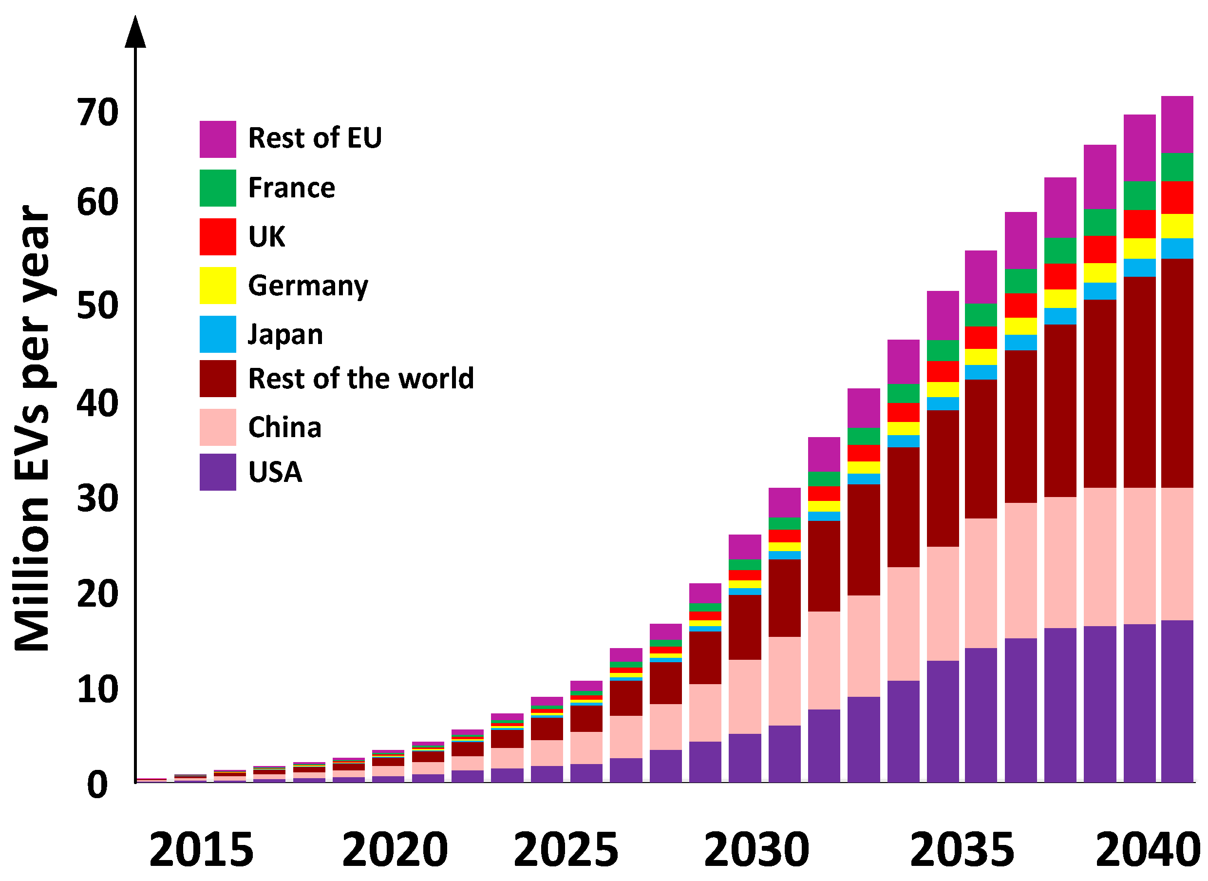
Figure 3.
The classification of OBC topologies for EV applications.
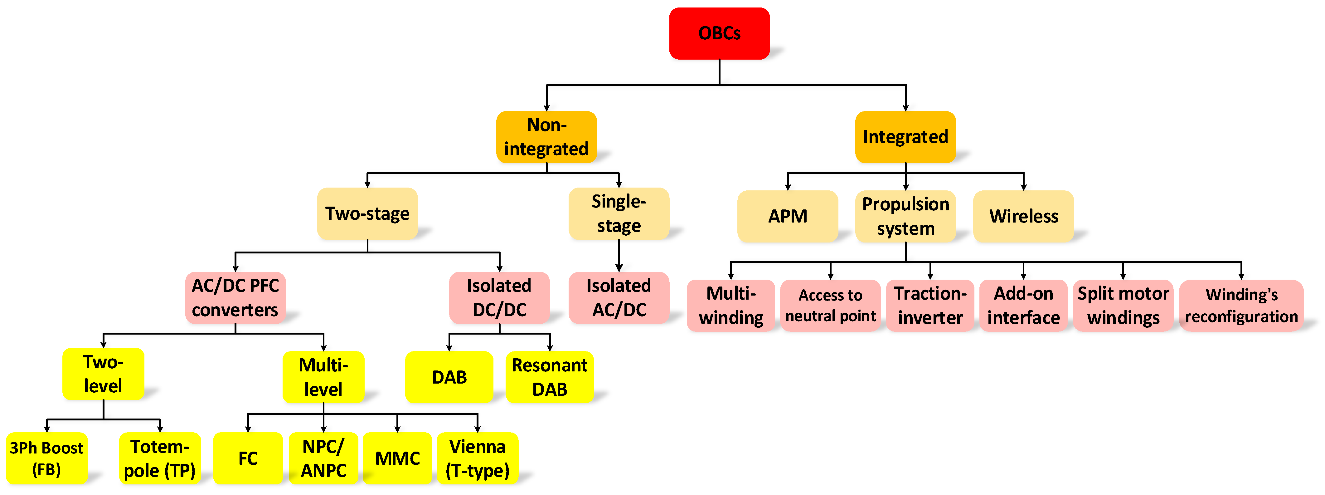
Figure 4.
Non-integrated OBCs: (a) two-stage OBC, including EMI filter, AC-DC PFC, DC link, and isolated DC-DC converter; (b) single-stage topology, including EMI filter and AC-DC PFC.
Figure 4.
Non-integrated OBCs: (a) two-stage OBC, including EMI filter, AC-DC PFC, DC link, and isolated DC-DC converter; (b) single-stage topology, including EMI filter and AC-DC PFC.
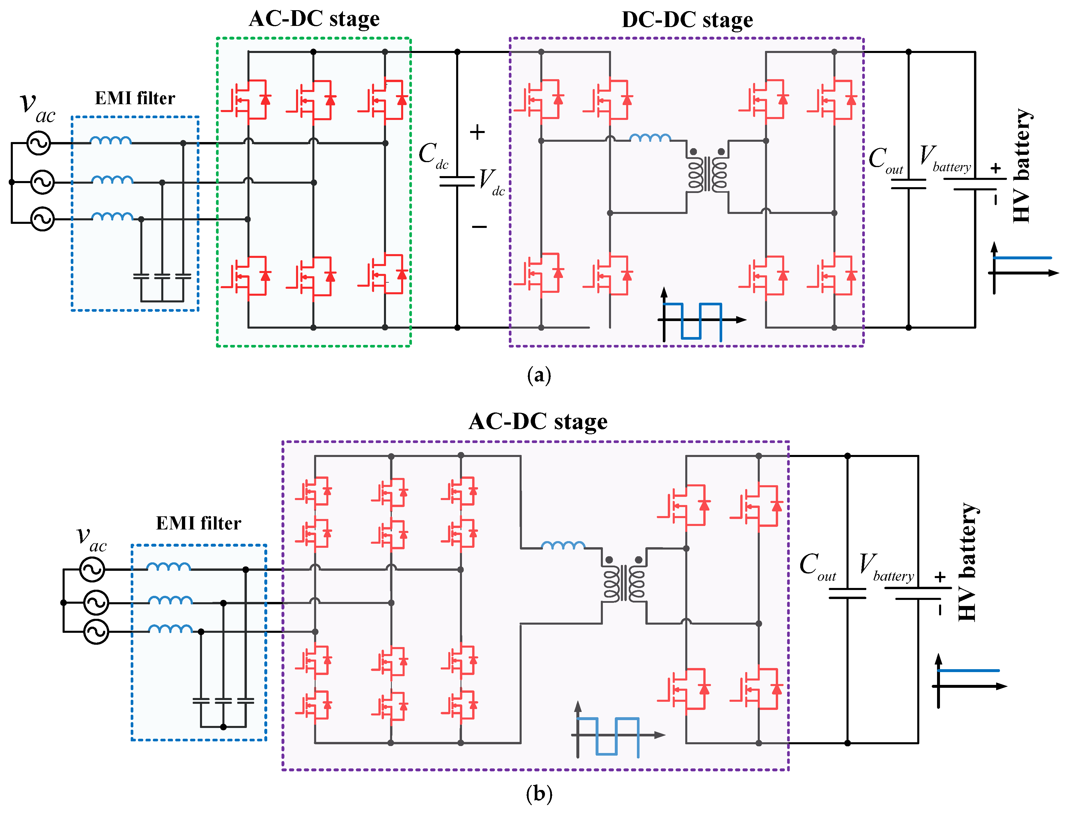
Figure 5.
Examples of two-level AC-DC PFCs for two-stage OBCs. (a) Three-phase boost PFC (full-bridge PFC) [96], (b) totem-pole PFC [10], (c) two-channel interleaved totem-pole PFC [11] and (d) three- channel interleaved totem-pole PFC [6].
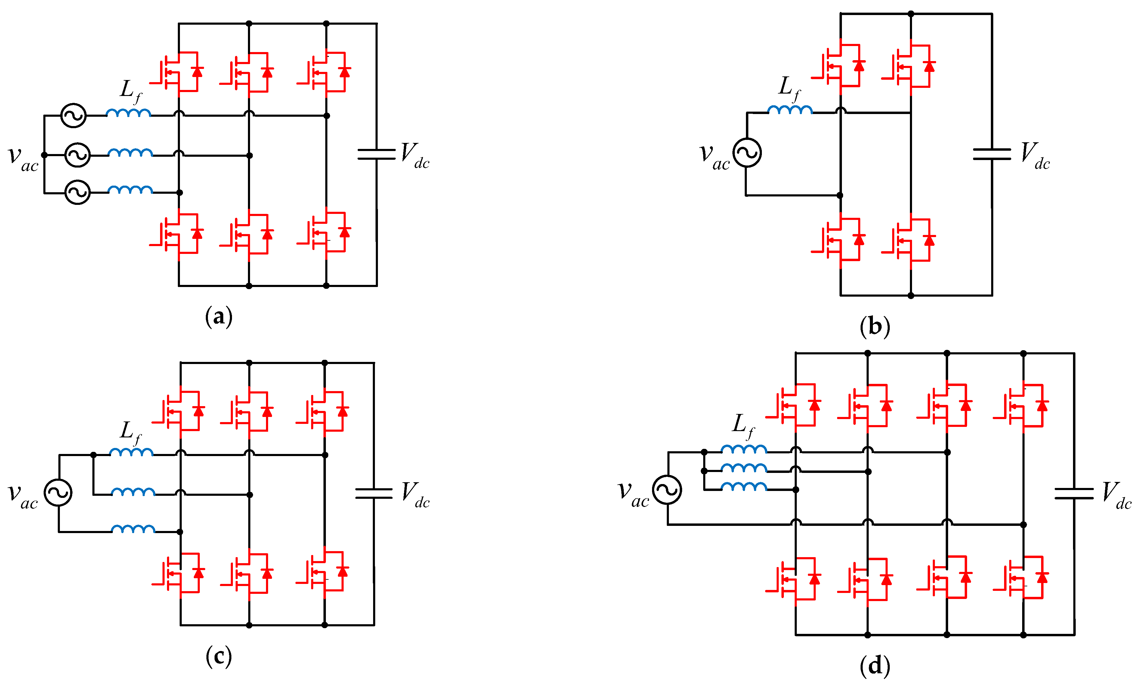
Figure 6.
Examples of multi-level AC-DC PFCs for two-stage non-integrated OBCs: (a) three-level T-type boost PFC (Vienna rectifier), (b) active-neutral-point-clamped (ANPC) converter, (c) flying-capacitor (FC) topology, and (d) modular multi-level converter.
Figure 6.
Examples of multi-level AC-DC PFCs for two-stage non-integrated OBCs: (a) three-level T-type boost PFC (Vienna rectifier), (b) active-neutral-point-clamped (ANPC) converter, (c) flying-capacitor (FC) topology, and (d) modular multi-level converter.

Figure 7.
Isolated DC-DC converter topologies for two-stage non-integrated OBCs: (a) dual active bridge (DAB) converter; (b) resonant DAB converter (CLLC).
Figure 7.
Isolated DC-DC converter topologies for two-stage non-integrated OBCs: (a) dual active bridge (DAB) converter; (b) resonant DAB converter (CLLC).

Figure 8.
Examples of two-level and multi-level variants of DAB and resonant DAB converter topologies for two-stage non-integrated OBCs: (a) two-level series-input–series-output DAB converter [115], (b) three-level ANPC dual active half-bridge topology [105], (c) three-level DAB converter with blocking capacitors [102], (d) three-level three-phase DAB converter [108], (e) two-level CLLC resonant converter with three modular transformers [110], (f) multi-level stacked-half-bridge with LCL-T network with DC blocking capacitors [1].


Figure 9.
Two-stage non-integrated isolated OBCs with totem-pole PFC and resonant DC-DC converters: (a) two-channel interleaved totem-pole PFC and single-phase CLLC resonant DAB converter [120], (b) two-channel interleaved totem-pole PFC and CLLC resonant converter [10], (c) four-channel interleaved totem-pole PFC with Return Path Windings and three-phase CLLC resonant converter [100], (d) two-channel interleaved totem-pole PFC and LLC resonant converter [124], (e) two-channel interleaved totem-pole PFC with Mode Switch Boost converter and LLC resonant converter [125].


Figure 10.
Two-stage non-integrated isolated OBCs with three-phase boost PFC and resonant DC-DC converters: (a) three-phase boost PFC and LLC resonant converter [126]; (b) three-phase boost PFC and two parallel-connected resonant LLC converters [127].

Figure 11.
Two-stage non-integrated isolated OBCs with diode bridge PFC and resonant DC-DC converters: (a) diode bridge and boost converter in the PFC stage and a resonant LLC DC-DC converter at the HV battery side [128]; (b) a diode bridge with an inrush current limiter and an interleaved boost converter at the grid side and two parallel-input–parallel-output (PIPO) LLC resonant converters at the HV battery side [129].

Figure 13.
Various categories of iOBCs: (a) propulsion system iOBC, (b) auxiliary power module (APM) iOBC, (c) wireless charger iOBC.
Figure 13.
Various categories of iOBCs: (a) propulsion system iOBC, (b) auxiliary power module (APM) iOBC, (c) wireless charger iOBC.

Figure 14.
Multi-winding propulsion system iOBC using a symmetrical six-phase machine [41].
Figure 14.
Multi-winding propulsion system iOBC using a symmetrical six-phase machine [41].

Figure 15.
Isolated bidirectional iOBC using reconfiguration of the motor’s winding [145].
Figure 15.
Isolated bidirectional iOBC using reconfiguration of the motor’s winding [145].

Figure 16.
A dual-motor dual-inverter topology as access to the motor’s neutral point iOBC [148].
Figure 16.
A dual-motor dual-inverter topology as access to the motor’s neutral point iOBC [148].

Figure 17.
Three-phase split motor windings iOBC [59].
Figure 17.
Three-phase split motor windings iOBC [59].

Figure 18.
Add-on interface iOBC using three-phase step-down FB converter and an EMI filter [63].
Figure 18.
Add-on interface iOBC using three-phase step-down FB converter and an EMI filter [63].

Figure 19.
Bidirectional traction inverter iOBC using an FB isolated boost converter and five additional auxiliary relay switches [65].
Figure 19.
Bidirectional traction inverter iOBC using an FB isolated boost converter and five additional auxiliary relay switches [65].

Figure 20.
Unidirectional and bidirectional converter topologies used as traction inverter iOBCs: (a) single-phase unidirectional [67], (b) single-phase unidirectional [68], (c) single-phase unidirectional [69], (d) single-phase unidirectional [70], (e) single-phase unidirectional [71], (f) single-phase unidirectional [67], (g) single-phase unidirectional [72], (h) single-phase unidirectional [73], (i) single-phase unidirectional [74], (j) single-phase bidirectional [75].


Figure 21.
Multiport converters for APM iOBCs: (a) single-stage bidirectional converter with bidirectional PFC converter, three-port HFT, bidirectional HB CLLC resonant converter, and FB LLC resonant [157]; (b) two-stage bidirectional converter with interleaved totem-pole PFC converters, CLLC resonant converter, three-port HFT, and interleaved buck converter [158,159].

Figure 22.
Highest level of power electronics integration: APM and traction inverter iOBC [160,161].

Table 1.
Recently published review papers on OBC solutions.
| Ref. | Contributions | Publication Year |
|---|---|---|
| [1] | Wired and wireless on-board and off-board battery chargers | 2021 |
| [4] | Single-stage and two-stage bidirectional isolated non-integrated OBCs and modulation techniques | 2023 |
| [6] | Single-stage and two-stage bidirectional non-integrated OBCs | 2024 |
| [31] | Power electronic converters for on-board and off-board chargers | 2023 |
| [33] | Propulsion system iOBCs | 2022 |
| [34] | Two-level and multi-level power electronic converters for OBCs and traction inverter iOBCs | 2023 |
| [35] | High-power integrated and non-integrated OBCs (≥7.4 kW) | 2019 |
| [75] | Propulsion system iOBCs | 2019 |
| [76] | Traction inverter integrated OBCs (iOBCs) | 2018 |
| [77] | Single-stage and two-stage non-integrated OBCs and propulsion system iOBCs | 2023 |
| Charging Level | Location | Supplied Voltage | Supply Type | Power Level | Current Level | Charging Time | Charging Rate | Driving Range | Connector |
|---|---|---|---|---|---|---|---|---|---|
| Level 1 (AC slow charging) | On-board (residential) | 120 Vac (US) 230 Vac (EU) | Single-phase | 3.7 kW | 12–16 A | 10–15 h | 16–50 kWh | 5 miles | SAE J1772 T1 (US) |
| Leve 2 (AC accelerated charging) | On-board (Residential or work place) | 240 Vac (US) 400 Vac (EU) | Single-phase Three-phase | 3.7–22 kW | 15–80 A | 3.5–7 h | 16–30 kWh | 10–20 miles | SAE J1772 T1 (US) IEC 62196 T2 (EU) GB/T20234 (China) |
| Level 3 (DC fast charging) | Off-board (Public places like gas stations) | 480 Vac (US) 400 Vac (EU) 300–600 Vdc | Three-phase | 50–350 kW | Maximum 400 A | 10–30 min | 20–50 kWh | >75 miles | CCS Combo 1 DC (US) CCS Comb2 2 DC (EU) GB/T20234 DC (China) SAE J3068 AC (US) IEC 62196 T2 AC (EU) GB/T20234 AC (China) |
| DC ultra-fast charging | Off-board (Public place like gas station) | >800 Vdc | Three-phase | >400 kW | >400 A | |10 min | 20–50 kWh | >100 miles | CCS/CHAdeMO (EU) |
Table 3.
Summary of international standards related to OBC charger development [34,79,80,85,86,87,88,89,90,91,92,93,94].
| Standard Code | Description |
|---|---|
| IEC 61851-1 | General requirements |
| IEC 61000-3 | Power quality regulations (maximum permissible THD of 20% and minimum acceptable PF of 0.95) |
| IEEE 519 | Maximum permissible THD of 7% |
| IEC 60950 | Galvanic isolation |
| IEC 62196 SAE J1772 CHAdeMO GB/T 20234 | Standards predominate in EU, the US, Japan, and China for connectors interfaces and inlets |
| IEEE 1547 IEEE 2030 IEC 62109 UL 1741 NB/T 33015 | Microgrid inverter standards for bidirectional OBCs when injecting power into a local grid |
| CISPR 25 (Class 1–5) ISO 11452 (Class 1–11) | Limitations on EMI radiations during the operation of the OBC |
| ISO 10605 | Immunity of a module against electrostatic discharge (ESD) |
| ISO 16750 UL 2202 | Electrical safety standards for OBCs, including leakage current, operational integrity, resistance to vibrations, and tolerance to environmental conditions (humidity, thermal, and vibration tests) |
| IEC 61850-90-8 ISO 15118 | V2G communication (bidirectional discharging/charging) |
| AEC-Q100 AEC-Q200 | Reliability standards |
Table 4.
Technical specifications of two-level and multi-level DAB-based converters for two-stage non-integrated OBCs.
Table 4.
Technical specifications of two-level and multi-level DAB-based converters for two-stage non-integrated OBCs.
| Ref. | Topology | Power Range | Switching Frequency | Output Voltage | Efficiency | Year |
|---|---|---|---|---|---|---|
| [98] | Two-level SISO DAB | 10 kW | 140–400 kHz | 250–100 Vdc | - | 2022 |
| [105] | Three-level ANPC DAB | 3.3 kW | 75–300 kHz | 800 Vdc | ~98% | 2022 |
| [107] | Three-level DAB | 3.5 kW | 50 kHz | 700 Vdc | ~95.5% | 2019 |
| [108] | Three-level DAB | 5 kW | 50 kHz | 1.5 kVdc | - | -- |
Table 5.
Technical specifications of two-level and multi-level resonant DAB-based converters for two-stage non-integrated OBCs.
Table 5.
Technical specifications of two-level and multi-level resonant DAB-based converters for two-stage non-integrated OBCs.
| Ref. | Topology | Power Range | Power Density | Switching Frequency | Output Voltage | Efficiency | Year |
|---|---|---|---|---|---|---|---|
| [109] | CLLC + a four-channel interleaved buck converter | -- | 6.1 kW/L | -- | 200∼800 Vdc | - | 2021 |
| [110] | Two-level CLLC with modular transformers | 11 kW | 14.6 kW/L | 500 kHz | 800 Vdc | 97.9% | 2022 |
| [111] | CLLC | 22 kW | 8 kW/L | 135–250 kHz | -- | 98.5% | -- |
| [113] | CLLC | 3.3 kW | 7.9 kW/L | 435–575 kHz | 400 Vdc | 97.6% | 2022 |
| [114] | HB CLLC | 1 kW | - | 391–500 kHz | 400 Vdc | 95.7% | 2020 |
| [115] | Multi-level stacked HB CL-T | 6.6 kW | 7.3 kW/L | 500 kHz | 150–950 Vdc | 98.2% | -- |
| [116] | LLC | 3.2 kW | 4 kW/L | 75–300 kHz | 400 Vdc | 98.5% | 2020 |
| [117] | CLLC | 18 kW | 8.7 kW/L | - | 400 Vdc | >98.8% | 2021 |
| [118] | CLLC | 3.3 kW | - | 140–180 kHz | 400 Vdc | 96–98% | 2017 |
| [119] | CLLC | 6 kW | 3 kW/L | - | 400 Vdc | >98% | 2017 |
Table 6.
Technical specifications of two-stage non-integrated isolated OBC solutions.
| Ref. | Power Conversion Stages | Output Voltage Range | Switching Frequency | Power Range | Power Density | Bidirectional | Isolated (IEC 60950) | Components | η | Year | ||
|---|---|---|---|---|---|---|---|---|---|---|---|---|
| AC-DC PFC | DC-DC | AC-DC PFC | DC-DC | |||||||||
| [6] | Totem pole | CLLC | 400 Vdc | 300 kHz | 300 kHz | 6.6 kW | 3.4 kW/L | Yes | Yes | 16 switches 3 inductors 3 capacitors 1 transformer | 96% | 2020 |
| [10] | Two-channel interleaved totem pole | CLLC | 400 Vdc | 120 kHz | 200–800 kHz | 6.6 kW | 3.8 kW/L | Yes | Yes | 14 switches 2 inductors 4 capacitors 1 transformer | 96.5% | 2021 |
| [100] | Four-channel interleaved totem pole | Three-phase CLLC | 800 Vdc | 350 kHz | 500 kHz | 11 kW | 3.2 kW/L | Yes | Yes | 22 switches 2 inductors 3 capacitors 1 transformer | 96% | 2022 |
| [101] | Totem pole | two-phase CLLC | 400 Vdc | 350 kHz | 500 kHz | 6.6 kW | 2.7 kW/L | Yes | Yes | 18 switches 1 inductor 6 capacitors 2 transformers | 96.2% | 2018 |
| [120] | Two-channel interleaved totem pole | single-phase CLLC | 400 Vdc | 300 kHz | 500 kHz | 6.6 kW | 2.3 kW/L | Yes | Yes | 18 switches 1 inductor 6 capacitors 2 transformers | 96.2% | 2018 |
| [121] | Totem pole | CLLC | 400 Vdc | 67 kHz | 148–300 kHz | 6.6 kW | 3.2 kW/L | Yes | Yes | 12 switches 3 inductors 4 capacitors 1 transformer | 97% | 2016 |
| [122] | Totem pole | two-phase CLLC | 400 Vdc | 350 kHz | 500 kHz | 6.6 kW | 8 kW/L | Yes | Yes | 18 switches 1 inductor 6 capacitors 2 transformers | 97.8% | 2018 |
| [123] | Totem pole | three-phase CLLC | 400 Vdc | 350 kHz | 500 kHz | 12.5 kW | 9.5 kW/L | Yes | Yes | 18 switches 1 inductor 6 capacitors 2 transformers | 97.3% | 2018 |
| [124] | Tow-channel interleaved totem pole | LLC | 240–420 Vdc | 66.7 kHz | 270–315 kHz | 6.6 kW | 2.7 kW/L | Yes | Yes | 16 switches 1 inductor 3 capacitors 1 transformer | 95.6% | 2019 |
| [125] | Tow-channel interleaved totem pole | LLC | 400 Vdc | 300 kHz | 300 kHz | 6.6 kW | 3.3 kW/L | Yes | Yes | 16 switches 2 diodes 4 inductors 4 capacitors 1 transformer | 94.7% | 2018 |
| [126] | Three-phase boost | LLC | 50 kHz | 90–150 kHz | 10 kW | N/A | Yes | Yes | 12 switches 5 inductors 5 capacitors 1 transformer | 96% | 2016 | |
| [127] | Three-phase boost | Two parallel connected LLC | 422.4 Vdc | 100 kHz | 100 kHz | 20 kW | N/A | No | Yes | 10 switches 8 diodes 7 inductors 6 capacitors 2 transformers | 96% | 2017 |
| [128] | Diode bridge + boost converter | HB LLC | ~400 Vdc | 90 kHz | 90–275 kHz | 10.5 kW | 1.75 kW/L | No | Yes | 9 switches 27 diodes 7 inductors 12 capacitors 3 transformers | 95.6% | 2016 |
| [129] | Diode bridge + inrush current limiter + interleaved boost converter | Two parallel-input–parallel-output FB LLC | 315–395 Vdc | 100 kHz | 100 kHz | 22 kW (EU) 17.2 kW (US & Japan) | 1.98 kW/L | No | Yes | 30 switches 42 diodes 18 inductors 18 capacitors 6 transformers | 94.5% | 2014 |
| [130] | Totem pole | CLLC | 400 Vdc | 67 kHz | 200 kHz | 6.6 kW | 2.2 kW/L | Yes | Yes | 12 switches 3 inductors 4 capacitors 1 transformer | 97% | 2019 |
Disclaimer/Publisher’s Note: The statements, opinions and data contained in all publications are solely those of the individual author(s) and contributor(s) and not of MDPI and/or the editor(s). MDPI and/or the editor(s) disclaim responsibility for any injury to people or property resulting from any ideas, methods, instructions or products referred to in the content. |
© 2024 by the authors. Licensee MDPI, Basel, Switzerland. This article is an open access article distributed under the terms and conditions of the Creative Commons Attribution (CC BY) license (https://creativecommons.org/licenses/by/4.0/).
Share and Cite
MDPI and ACS Style
Nasr Esfahani, F.; Darwish, A.; Ma, X.; Twigg, P. Non-Integrated and Integrated On-Board Battery Chargers (iOBCs) for Electric Vehicles (EVs): A Critical Review. Energies 2024, 17, 2285. https://doi.org/10.3390/en17102285
AMA Style
Nasr Esfahani F, Darwish A, Ma X, Twigg P. Non-Integrated and Integrated On-Board Battery Chargers (iOBCs) for Electric Vehicles (EVs): A Critical Review. Energies. 2024; 17(10):2285. https://doi.org/10.3390/en17102285
Chicago/Turabian StyleNasr Esfahani, Fatemeh, Ahmed Darwish, Xiandong Ma, and Peter Twigg. 2024. "Non-Integrated and Integrated On-Board Battery Chargers (iOBCs) for Electric Vehicles (EVs): A Critical Review" Energies 17, no. 10: 2285. https://doi.org/10.3390/en17102285
Note that from the first issue of 2016, this journal uses article numbers instead of page numbers. See further details here.