
Cross-Water–Air Optical Wireless Communication Using Orthogonal Time–Frequency Space Modulation

1
School of Electronics and Information, Northwestern Polytechnical University, Xi’an 710065, China
2
School of Information Engineering, Xi’an University, Xi’an 710065, China
3
School of Marine Science and Technology, Northwestern Polytechnical University, Xi’an 710065, China
*
Author to whom correspondence should be addressed.
Symmetry 2024, 16(5), 571; https://doi.org/10.3390/sym16050571
Submission received: 1 April 2024
/
Revised: 26 April 2024
/
Accepted: 1 May 2024
/
Published: 7 May 2024
(This article belongs to the Special Issue Symmetry and Its Application in Wireless Communication)
Abstract
:This paper examines the communication difficulties encountered in cross-media wireless optical transmission through simulated research on the utilization of orthogonal time and frequency space (OTFS) modulation technology. Our analysis and comparison demonstrate that OTFS significantly improves the reliability and throughput of data transmission in intricate multipath channel settings. In contrast to conventional orthogonal frequency division multiplexing (OFDM) technology, OTFS displays better resilience and transmission effectiveness. We foresee additional enhancements and progress in OTFS technology to present a sturdier and more efficient resolution for wireless communication, thereby providing valuable perspectives and encouragement for associated research initiatives. Our results underscore the capability of OTFS technology to transform wireless communication systems in demanding multipath channel conditions.
1. Introduction
Recently, the integration of underwater unmanned vehicles (UUVs) and aerial unmanned vehicles (UAVs) has sparked significant progress in autonomous systems. This blending of the two areas has created opportunities for innovative cross-domain applications, transforming sectors such as environmental monitoring and defense operations. An essential hurdle in fully leveraging this integration is the establishment of effective and dependable communication channels between UUVs and mobile UAVs, particularly in settings where conventional communication approaches may face constraints [1,2,3,4]. One potential solution to address the challenges of communication between UUVs and mobile UAVs is to explore the use of advanced networking technologies such as cognitive radio networks, which can dynamically adapt to changing environmental conditions and optimize communication performance [5,6].
In addition, error correction coding schemes such as Reed-Solomon codes and convolutional codes are also incorporated to enhance the reliability of communication links in challenging environments. Optical wireless communication is becoming a viable solution for overcoming communication obstacles in scenarios involving water, air, and land boundaries. To enhance system performance in scenarios with restricted bandwidth, different modulation techniques like on–off keying (OOK) modulation, pulse position modulation (PPM), pulse amplitude modulation (PAM), quadrature amplitude modulation QAM, and orthogonal frequency division modulation (OFDM) are explored to increase transmission speeds, spectral efficiency, and system dependability [7,8,9].
In the realm of cross-media communication, conventional modulation techniques such as OFDM have played crucial roles. Optical orthogonal frequency division multiplexing (O-OFDM) is a specialized technology that employs orthogonal subcarriers for subcarrier intensity modulation. It is widely used in specific wireless optical communication systems [10,11,12]. For example, in a study by Chen et al. (2017), a transmission speed of 5.5 Gbps was achieved for uplink and downlink over a 26 m water–air channel using the OFDM technique. Another research paper [13] evaluated the performance of three prevalent O-OFDM schemes with SiPM receivers. The study concluded that DCO-OFDM provides the most extensive operational link range while maintaining the target achievable bit error rate (BER). Moreover, the study highlighted the importance of considering the effects of various environmental conditions on the performance of optical communication systems utilizing O-OFDM schemes.
To address the challenges posed by complex channels in OFDM, the Orthogonal time–frequency spacing (OTFS) technique has emerged as a promising solution [14,15], which is a potential waveform candidate that is frequently used in sixth-generation (6G) wireless communication networks and is shown to improve performance in high-mobility scenarios [16]. OTFS utilizes a nonlinear modulation method to convert signals in the time-frequency domain, optimizing signal transmission in scenarios with multiple propagation paths. A notable advantage of OTFS is its utilization of the discrete Doppler effect within multipath environments, leading to a notable improvement in signal transmission efficiency. By employing a transformation from the time-frequency domain of conventional OFDM signals, OTFS achieves spectral concentration in the time domain. This concentration focuses energy on specific time instances, thus reducing signal distortion and interference arising from multipath propagation. Consequently, OTFS enhances the resilience and dependability of communication systems in high-speed mobile settings and intricate channel conditions [17]. This improvement in signal transmission efficiency is especially advantageous in situations where it is crucial to uphold high data rates and ensure reliable communication links. In the underwater scenario, OTFS modulation has been shown to have a promising application in acoustic networking [18].
The research investigated underwater acoustic communication involving four users through a vertically configured time-varying underwater acoustic channel spanning 1 km, utilizing massive MIMO OFDM-based OTFS systems. The study achieved an impressive throughput of up to 198.7 kbps per underwater vehicle [19]. Additionally, in a different study [20], a novel DC-biased OWC scheme for Orthogonal Time–Frequency Multiplexing (OTFM) was introduced, exhibiting superior performance compared to conventional DC-polarized OFDM schemes. Moreover, research [21] indicated that OTFS surpasses OFDM and GFDM concerning the Peak-to-Average Power Ratio (PAPR).
In this context, the proposed cross-water-air bound OTFS optical wireless communication solution aims to address the specific communication needs of UUVs and moving UAVs, highlighting the fundamental principles of OTFS modulation and its efficacy in mitigating the obstacles posed by dynamic and dispersive environments. This paper presents a new cross-water-air bound OTFS optical wireless communication solution designed to meet the communication requirements of UUVs and moving UAVs. We delve into the basic principles of OTFS modulation and emphasize its effectiveness in overcoming the challenges presented by dynamic and dispersive environments.
2. Optical OTFS for Cross-Water–Air System
In this section, we explore the transmission of the OTFS signal, the channel model, and the processing involved in receiving the signal.
2.1. Transmitted Signal
The DCO-OTFS modulation technique provides similar benefits to DC-biased OFDM (DCO-OFDM) and aligns with our system design, illustrated in Figure 1. Light-emitting diodes (LEDs) are commonly employed as the primary light source in visible light communication systems, promoting the widespread use of intensity modulation/direct detection (IM/DD) modulation [22]. Alongside the concept of DC-biased OFDM (DCO-OFDM), we opt for DCO-OTFS as our modulation technique, as shown in Figure 1. In this diagram, binary data undergo modulation using L-QAM and are then mapped onto the complex plane. Subsequently, the inverse symplectic Fourier fast transform (ISFFT) is applied. Given the use of IM/DD, it is essential to ensure that the OTFS signal in the time-frequency domain is real-valued. Thus, a Hermitian symmetric signal must be generated before the Heisenberg transform. To prevent the transmission of negative signals, a DC bias is introduced before driving the LED with the signal.
At the transmitter, we assume that a single frame consists of samples, where M indicates the number of subcarriers and N represents the number of time slots. Initially, the th L-QAM data symbol in the delay-Doppler (DD) domain, generated using quadrature amplitude modulation (QAM), can be transformed into the time-frequency (TF) domain through the use of the inverse symplectic Fourier transform (ISFFT). In the time-frequency domain, the th sample, , can be obtained by
As mandated by the Hermitian symmetry property, the signal’s real and imaginary components are required to display symmetry around the origin in the time-frequency domain. To preserve the signal’s real-valued nature, a transformation maintaining Hermitian symmetry is employed on the signal within the TF domain, drawing on the Hermitian symmetry found in real-valued optical orthogonal frequency-division multiplexing (O-OFDM) systems for inspiration. In the envisaged DCO-OTFS system, the modulated data must adhere to the following criteria:
where represents the complex conjugate operation, and .
Similar to (2), we have .
The conversion process entails mapping the signal from the frequency-time domain, labeled as , to the OTFS transmitted signal using the Heisenberg transform. Subsequently, the signal in the frequency-time domain, denoted as , is transformed into the OTFS transmitted signal via the Heisenberg transform.
The signal sent according to Equation (4) is a sum involving the indices k and l. In this sum, is multiplied by , where T stands for the sampling interval, and denotes the transmitted pulse.
To prevent the transmission of negative-valued signals, a direct current (DC) bias is introduced. Consequently, the optical orthogonal frequency-division multiplexing (OTFS) signal with DC bias can be expressed as
Normally, the bias d is set to approximately half of the maximum permissible power limit for transmission.
The DCO-OTFS transmitted signal is affected by the sea-air channel effects, represented by , as it travels through this medium. The channel response, also labeled as , describes how the sea-air channel influences the transmitted DCO-OTFS signal within this environment. To mitigate inter-symbol interference, a cyclic prefix (CP) is appended to the signal following the Heisenberg transform. Additionally, a DC bias is incorporated to prevent zero-clipping. Subsequently, the DCO-OTFS signal is transmitted through the sea-air channel characterized by .
2.2. Channel Model
To thoroughly examine the channel model in this specific scenario, it is crucial to consider the various factors influencing the transmission of the light signal. These factors encompass scattering phenomena, transitions between different mediums, and the dynamic nature of the channel influenced by the UAV’s movement. The captured light signal experiences additional attenuation and scattering due to atmospheric conditions and the UAV’s motion. In contrast to conventional OWC systems, the channel under scrutiny in this research is particularly intricate due to the involvement of multiple mediums for signal propagation. Initially emitted from a UUV, the light signal encounters scattering and attenuation in water, followed by further scattering induced by the irregular sea surface. Ultimately, the UAV in flight receives the light signal.
We start by examining the channel characteristics of seawater, which play a crucial role in determining the efficiency of OWC systems. The behavior of light in water is heavily influenced by its inherent optical properties, particularly absorption and scattering phenomena. When a parallel light beam with a wavelength and width enters the water with an initial power of , it undergoes the absorption and scattering processes, leading to the light’s output power . According to the law of energy conservation [23], the sum of absorption, scattering, and output powers must be equal to the input power:
The absorbance and scattering coefficients can be calculated by applying the definitions of absorbance and scattering, taking into account the width of the incident light beam .
The attenuation coefficient of light is the sum of absorption and scattering coefficients:
The light power I after propagating a distance z can be expressed using the attenuation coefficient:
where represents the power of the transmitted light.
The scattering phase function is utilized to represent the probability distribution of new propagation directions after scattering events. A commonly employed function for this purpose is the Henyey–Greenstein (HG) function [23]:
The scattering anisotropy factor denoted as g, plays a crucial role in determining the scattering behavior. A value of 1 for g indicates a prevalence of forward scattering, while a value of suggests a tendency towards backscattering. The determination of the volume scattering function for various oceanic categories is based on empirical data obtained from measurements [24]. Moreover, the scattering phase function is fundamental in illustrating the probability distribution of new propagation directions following scattering, with the Henyey–Greenstein (HG) function being commonly utilized for this purpose [23].
At the interface of air and water, disruptions induced by elements like wind and waves can result in deflection, reflection, and refraction in the optical pathway, posing difficulties in aligning the transmission and reception points. The P-M spectrum is frequently employed to replicate the ocean surface. Pierson and Moskowitz analyzed wind and wave data from the Pacific Ocean, formulating distinct dimensionless spectra to represent them.
where g represents the local gravitational acceleration, is dimensionless with a value of , denotes the angular frequency, is a constant set at 0.74, and U stands for the wind speed at a height of 19.5 m above the sea level. The directional function , primarily derived from observational statistics, is introduced by the International Towing Tank Conference (ITTC) as
where denotes the angle between the wave propagation direction and the current wind direction. Generally, the sea surface directional spectrum is commonly expressed as the product of two functions as
To derive the channel impulse response (CIR) for the sea–air optical channel, the information carried by received photons undergoes analysis post Monte Carlo simulations (MCS) [25]. Each photon’s data encompasses its total traversal distance within the channel, convertible to the photon’s perceived time using the speed of light in both seawater and air. By summing the arrival times of all photons and plotting the distribution of photon weights across different times, the pulse time domain response is obtained. Under the assumption of a ray-based quasi-static propagation channel, the complex-valued Doppler-variant channel impulse response is delineated in terms of delay and Doppler frequency as
In the given context, P denotes the number of propagation paths and stands for the Dirac delta function. The variables and in the equation represent the complex gain and phase shift linked to each propagation path, respectively.
2.3. Received Signal Processing
The receiver functions as the opposite process of the transmitter. The signal captured by the avalanche photodiode (APD) receiver can be expressed as
denotes the additive white Gaussian noise. Following this, the received signal goes through DC bias removal and CP removal. The receiver utilizes the receiving pulse for matched filtering. The cross-ambiguity function is employed to obtain the matched filter output, allowing the receiver to effectively extract the transmitted information from the received signal.
The symbols obtained in the time–frequency domain, represented as , are obtained by sampling the cross-ambiguity function at and . The symbols in the time–frequency domain are acquired by sampling the cross-ambiguity function at and .
This process corresponds to the Wigner Transformation, as illustrated in Figure 1. It involves converting the time-domain signal into the time-frequency domain signal . Subsequently, the time-frequency domain signal is further converted into the DD domain signal using the SFFT as
In the end, the signal is transmitted in the DD domain following demodulation and conversion from parallel to serial. The conversion of the time-frequency domain signal into the Dp domain signal through the SFFT is a vital stage in the signal processing sequence before the ultimate transmission of the signal in the DD domain.
3. Simulation Results and Discussions
In this section, we carry out simulation experiments to examine the communication performance of the OTFS method in the context of cross-medium wireless optical communication [25,26].
The simulation scenario illustrated in Figure 2 portrays an LED light source emitting light beams continuously underwater. These beams are dispersed by water particles and bent by uneven surface inclines formed by tides and wind. An aircraft travels in a linear path towards the zenith of the light source, upholding a 100 m distance from the vertical point and moving parallel to it. Communication between the aircraft and the light source is established during this phase.
The simulation experiments consist of two main parts: (a) Utilizing the Monte Carlo method to replicate the communication channel and determine the CIR. (b) Evaluating the properties of CIR within the DD domain and comparing their Bit Error Rates (BER) with conventional OFDM modulation. Table 1 displays the essential parameters necessary for channel simulation.
The simulation experiments revealed a significant relationship between wind speed and sea surface wave characteristics. Lower wind speeds were found to result in faster local variations on the sea surface and increased fluctuations in wave height. This study introduces a wave model that considers various wind speeds based on the JONSWAP spectrum and the directional spectrum recommended by ITTC, within a fixed wind field spanning 1000 km. The sea surface was simulated using Monte Carlo simulation and FFT based on the spectrum. Initially, the system’s white noise was Fourier transformed and then convoluted with the sea surface power spectrum. Subsequent Fourier inverse transformation produced the sea surface roughness function, and discrete samples of the sea surface elevation were obtained following the sampling theorem. The simulation results, illustrated in Figure 3, demonstrate that lower wind speeds accelerate local sea surface variations and increase wave height fluctuations. Conversely, higher wind speeds lead to smoother wave height curves, elongated distances between wave peaks and troughs, and a gradual decrease in the peak spectral frequency, concentrating the wave spectrum energy within a lower frequency range.
The model of CIR in the DD domain, as depicted in Equation (19), enables the analysis of different channel conditions of the aircraft at various speeds, as shown in Figure 4. By employing Equation (19), we can represent the CIR within the DD domain, with Figure 4 demonstrating the diverse channel conditions of the aircraft at different velocities.
The outcomes of our simulation experiments indicate that OTFS performs better than OFDM in terms of bit error rate, especially in high-mobility scenarios within wireless optical communication. Our objective is to conduct a comparative analysis between OFDM and OTFS methods in these experiments. We have employed QAM as our modulation technique, as shown in Figure 5. The simulation encompasses modulation orders of 2, 4, 8, and 16, with both M and N values set at 32, along with a subcarrier spacing of 500 kHz. Through the transmission of 100 data frames, it becomes evident that OTFS exhibits a lower bit error rate when contrasted with OFDM. This finding underscores the superior performance of OTFS over conventional OFDM in wireless optical communication, particularly in scenarios requiring high mobility.
This pattern indicates that as the aircraft’s speed increases, there is a corresponding rise in the bit error rate (BER), in line with the expected findings. The data depicted in Figure 6 showcase the error rate performance of data transmission on the aircraft across various flight speeds (50 m/s, 100 m/s, and 200 m/s) using a modulation order of 4-QAM. The light source is inclined at a 30-degree angle in the positive y-axis direction. It is evident that as the speed of the aircraft escalates, the BER also escalates, confirming our predicted outcome. This occurrence is especially evident in situations where the aircraft is moving at higher velocities, leading to a more pronounced influence on the quality of transmission. The influence becomes more substantial as the speed of the aircraft increases, as depicted in Figure 6.
Furthermore, we investigate how adjusting the tilt angle of the light source can impact the transmission quality in the optical communication system. The simulation results are shown in Figure 7. In this figure, we examine a scenario where an aircraft is traveling along a straight path on the negative x-axis and consider various configurations: a light source with no tilt, a light source tilted 30 degrees along the positive x-axis, and a light source tilted 30 degrees along the positive y-axis. In subfigure (a), the aircraft is directly above the light source at a speed of 0 m/s, while subfigure (b) shows the aircraft moving at 200 m/s in the negative x-axis direction. The findings suggest that changing the tilt angles of the light source can lead to the deflection or refraction of optical signals during transmission, impacting the overall transmission quality of the optical communication system and increasing the bit error rate.
This analysis helps us to comprehend the complex connection between data transmission rates and the corresponding bit error rate, emphasizing the challenges brought about by high-speed transmission concerning signal quality and channel requirements. Additionally, we are investigating the impact of various data transmission rates on the bit error rate, as shown in Figure 8. Higher data transmission rates necessitate broader bandwidth and higher frequencies, which place more stringent demands on signal quality and transmission channels. Consequently, high-speed transmission may lead to a heightened bit error rate due to the increased vulnerability to noise, interference, and signal distortion. The simulation parameters involve a flight velocity of 200 m/s and modulation schemes of 4−QAM, 8−QAM, and 16-QAM. By setting M to 32, the subcarrier spacing varies from 100 kHz to 1 MHz, progressively increasing the symbol transmission rate from 3.2 Mbps to 32 Mbps.
Moreover, the research explores how the inclination angle of the light emitter affects the bit error rate performance at different velocities, shedding light on how this factor impacts communication efficiency. The findings from the simulations provide crucial information on the communication efficacy of the OTFS technique in a wireless optical environment with diverse mediums. The evaluation highlights the advantages of this method compared to conventional OFDM in high-mobility settings and demonstrates the influence of various parameters on system performance.
4. Conclusions and Future Work
This paper conducts an in-depth simulation study on communication challenges faced in cross-media wireless optical transmission scenarios, specifically examining the use of OTFS modulation technology. Through experimental simulations, we evaluated the OTFS performance in complex multipath channel environments and contrasted it with traditional OFDM. Our results demonstrate that OTFS shows promise in greatly improving both data transmission reliability and throughput under challenging channel conditions. The study suggests that OTFS modulation technology has the potential to significantly enhance data transmission reliability and throughput compared to conventional OFDM in demanding multipath channel scenarios.
In forthcoming research, it is essential to model and analyze the peak-to-average power ratio of the optical OTFS signal. Given the limitation on peak transmitted power, any OTFS signal exceeding this threshold will experience hard clipping. Future studies should take into account these clipping effects and nonlinear distortions for a comprehensive analysis.
Author Contributions
Conceptualization, D.L.; methodology, D.L. and Y.G.; software, D.L.; validation, D.L.; formal analysis, D.L.; investigation, Y.G.; resources, D.L.; data curation, D.L.; writing—original draft preparation, D.L.; writing—review and editing, D.L. and Y.G.; visualization, D.L.; supervision, J.L.; project administration, Jie Lian; funding acquisition, Y.G. and J.L. All authors have read and agreed to the published version of the manuscript.
Funding
This work was supported by the Scientific Research Plan of the Education Department of Shaanxi Province (Grant No. 20JK0873), Xi’an Science and Technology Association Youth Talent Lifting Plan (Grant No. 959202313081), Xi’an Science and Technology Plan (Grant No. 23GXFW0079), and Xi’an University Three-Year Action Plan (Grant No. 2021XDJH30).
Data Availability Statement
Data may be obtained from the authors upon request.
Conflicts of Interest
The authors declare no conflicts of interest.
References
- Khan, R.; Qiao, G. A Survey of Underwater Acoustic Communication and Networking Techniques. Res. J. Appl. Sci. Eng. Technol. 2013, 5, 778–789. [Google Scholar] [CrossRef]
- Lin, T.; Huang, N.; Gong, C.; Luo, J.; Xu, Z. Preliminary characterization of coverage for water-to-air visible light communication through wavy water surface. IEEE Photonics J. 2021, 13, 1–13. [Google Scholar] [CrossRef]
- Sun, X.; Kong, M.; Shen, C.; Kang, C.H.; Ng, T.K.; Ooi, B.S. On the realization of across wavy water-air-interface diffuse-line-of-sight communication based on an ultraviolet emitter. Opt. Express 2019, 27, 19635–19649. [Google Scholar] [CrossRef] [PubMed]
- Fu, C.; Lin, T.; Gong, C.; Huang, N.; Wei, T.; Liu, X.; Tang, L.; Su, L.; Luo, J.; Xu, Z. Anti error and erasure coding for water-to-air visible light communication through wavy water surface with wave height up to 0.6 meters. Opt. Express 2022, 30, 18743–18761. [Google Scholar] [CrossRef] [PubMed]
- Li, Y.; Liang, H.; Gao, C.; Miao, M.; Li, X. Temporal dispersion compensation for turbid underwater optical wireless communication links. Opt. Commun. 2019, 435, 355–361. [Google Scholar] [CrossRef]
- Geldard, C.T.; Guler, E.; Hamilton, A.; Popoola, W.O. An Empirical Comparison of Modulation Schemes in Turbulent Underwater Optical Wireless Communications. J. Light. Technol. 2021, 40, 2000–2007. [Google Scholar] [CrossRef]
- Yang, Y.; Yang, F.; Liu, W.; Zhao, P.; Zhang, J.; He, F.; Lan, X. Performance analysis of dual-mode adaptive switching blind equalization algorithm in an underwater wireless optical communication system. Opt. Eng. 2021, 60, 126104. [Google Scholar] [CrossRef]
- Alkhasraji, J.; Tsimenidis, C. Coded OFDM over short range underwater optical wireless channels using LED. In Proceedings of the IEEE Proc. Oceans 2017-Aberdeen, Aberdeen, UK, 19–22 June 2017; pp. 1–7. [Google Scholar]
- Chi, N.; Zhao, Y.; Shi, M.; Zou, P.; Lu, X. Gaussian kernel-aided deep neural network equalizer utilized in underwater PAM8 visible light communication system. Opt. Express 2018, 26, 26700–26712. [Google Scholar] [CrossRef] [PubMed]
- Song, X.; Zhao, Z.; Wei, Y.; Wang, M. Research and performance analysis on multi-point light-emitting diodes-array intra-vehicle visible light communication systems with DC-biased optical—Orthogonal frequency-division multiplexing. Int. J. Distrib. Sens. Netw. 2017, 13, 1550147717729785. [Google Scholar] [CrossRef]
- Sharma, M.; Chadha, D.; Chandra, V. Capacity evaluation of MIMO-OFDM Free Space Optical communication system. In Proceedings of the 2013 Annual IEEE India Conference (INDICON), Mumbai, India, 13–15 December 2013; pp. 1–4. [Google Scholar] [CrossRef]
- Bekkali, A.; Naila, C.B.; Kazaura, K.; Wakamori, K.; Matsumoto, M. Transmission Analysis of OFDM-Based Wireless Services Over Turbulent Radio-on-FSO Links Modeled by Gamma–Gamma Distribution. IEEE Photonics J. 2010, 2, 510–520. [Google Scholar] [CrossRef]
- Essalih, T.; Khalighi, M.A.; Hranilovic, S.; Akhouayri, H. Optical OFDM for SiPM-Based Underwater Optical Wireless Communication Links. Sensors 2020, 20, 6057. [Google Scholar] [CrossRef] [PubMed]
- Hadani, R.; Rakib, S.; Tsatsanis, M.; Monk, A.; Goldsmith, A.J.; Molisch, A.F.; Calderbank, R. Orthogonal Time Frequency Space Modulation. In Proceedings of the 2017 IEEE Wireless Communications and Networking Conference (WCNC), San Francisco, CA, USA, 19–22 March 2017; pp. 1–6. [Google Scholar] [CrossRef]
- Hadani, R.; Monk, A. OTFS: A New Generation of Modulation Addressing the Challenges of 5G. arXiv 2018, arXiv:1802.02623. [Google Scholar]
- Umakoglu, I.; Namdar, M.; Basgumus, A.; Özyurt, S.; Kulaç, S. BER Performance Analysis for NOMA Systems with OTFS Modulation. In Proceedings of the 2023 31st Signal Processing and Communications Applications Conference (SIU), Istanbul, Turkiye, 5–8 July 2023; pp. 1–4. [Google Scholar] [CrossRef]
- Hong, Y.; Thaj, T.; Viterbo, E. Chapter 3—OFDM review and its limitations. In Delay-Doppler Communications; Hong, Y., Thaj, T., Viterbo, E., Eds.; Academic Press: Cambridge, MA, USA, 2022; pp. 29–46. [Google Scholar] [CrossRef]
- Zhang, Y.; Zhang, S.; Wang, B.; Liu, Y.; Bai, W.; Shen, X. Deep Learning-Based Signal Detection for Underwater Acoustic OTFS Communication. J. Mar. Sci. Eng. 2022, 10, 1920. [Google Scholar] [CrossRef]
- Bocus, M.J.; Doufexi, A.; Agrafiotis, D. Performance of OFDM-based massive MIMO OTFS systems for underwater acoustic communication. IET Commun. 2020, 14, 588–593. [Google Scholar] [CrossRef]
- Zhong, J.; Zhou, J.; Liu, W.; Qin, J. Orthogonal Time-Frequency Multiplexing With 2D Hermitian Symmetry for Optical-Wireless Communications. IEEE Photonics J. 2020, 12, 1–10. [Google Scholar] [CrossRef]
- Surabhi, G.D.; Augustine, R.M.; Chockalingam, A. Peak-to-Average Power Ratio of OTFS Modulation. IEEE Commun. Lett. 2019, 23, 999–1002. [Google Scholar] [CrossRef]
- Myung, H.G.; Lim, J.; Goodman, D.J. Single carrier FDMA for uplink wireless transmission. IEEE Veh. Technol. Mag. 2006, 1, 30–38. [Google Scholar] [CrossRef]
- Mobley, C. Light and Water: Radiative Transfer in Natural Waters. Bull. Am. Meteorol. Soc. 1994, 76, 60–63. [Google Scholar]
- Smith, R.C.; Austin, R.W.; Petzold, T.J. Volume-scattering functions in ocean waters. In Suspended Solids in Water; Gibbs, R.J., Ed.; Springer US: Boston, MA, USA, 1974; pp. 61–72. [Google Scholar]
- Cox, W.C. Simulation, Modeling, and Design of Underwater Optical Communication Systems. Ph.D. Thesis, North Carolina State University, Raleigh, NC, USA, 2012. [Google Scholar]
- Gabriel, C.; Khalighi, M.A.; Bourennane, S.; Léon, P.; Rigaud, V. Monte-Carlo-based channel characterization for underwater optical communication systems. J. Opt. Commun. Netw. 2013, 5, 1–12. [Google Scholar] [CrossRef]
Figure 1.
Block diagram of OTFS sea–air system.

Figure 2.
Scenarios of collapsing medium optical communication.
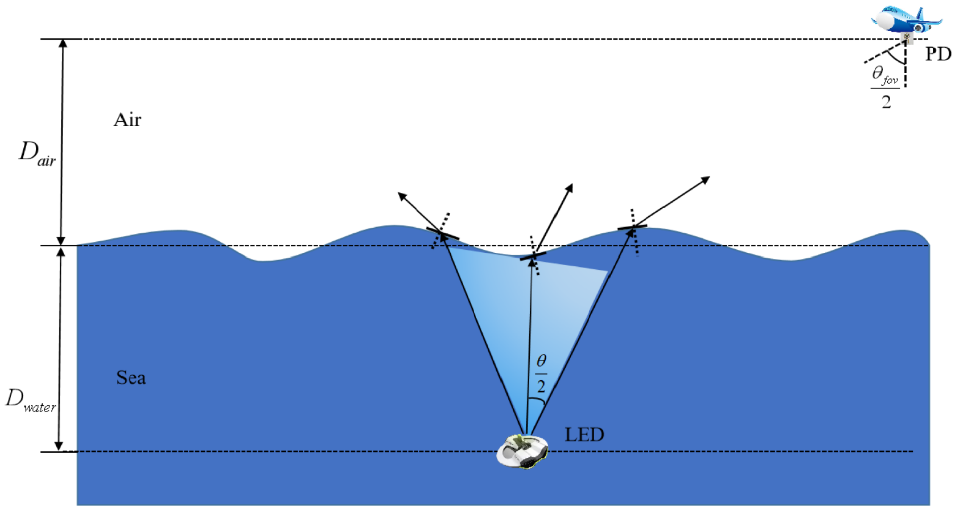
Figure 3.
Water-air surface model under different wind speeds.

Figure 4.
CIR in DD domain at an aircraft speed of (a) 50 m/s and (b) 200 m/s.
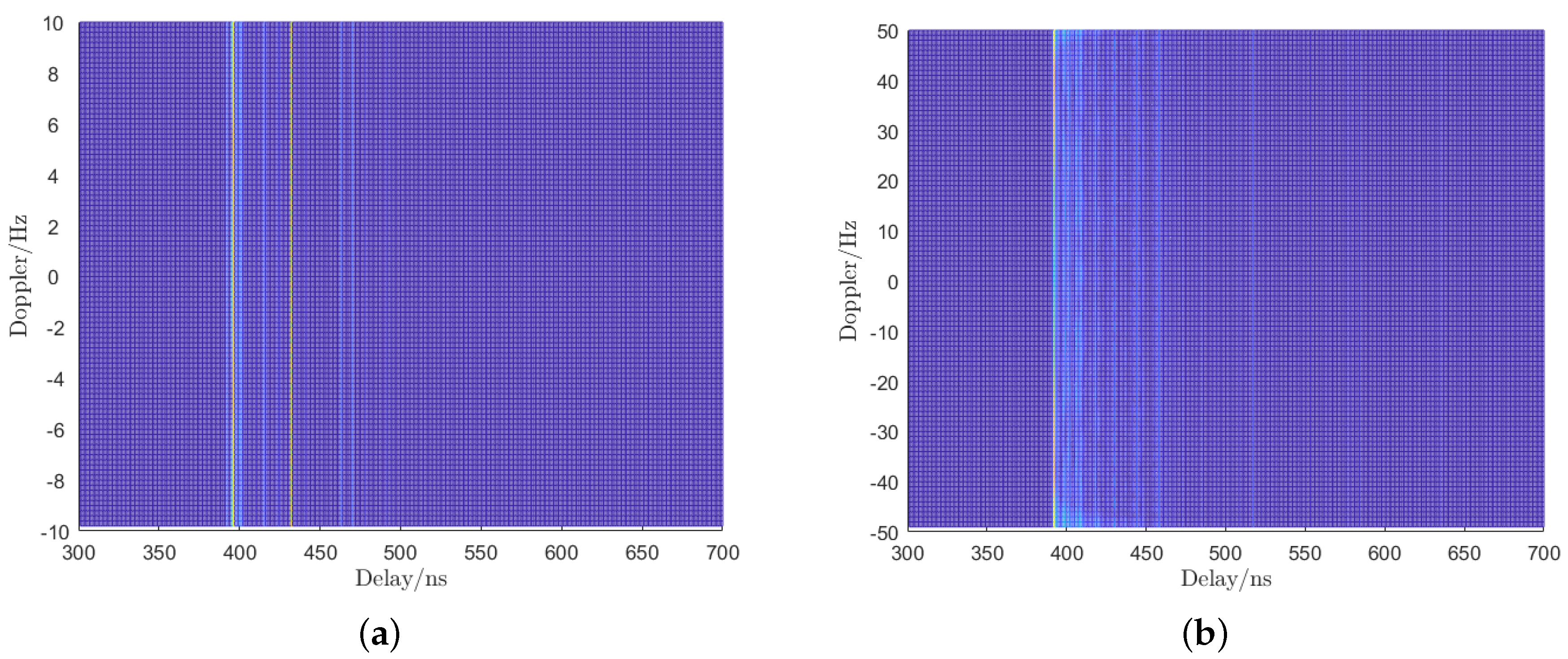
Figure 5.
BER performance with different SNR. (a) 2−QAM. (b) 4−QAM. (c) 8−QAM. (d) 16−QAM.

Figure 6.
BER performance with different aircraft speeds.

Figure 7.
BER performance with a light source tilt angle of 0 degrees and 30 degrees. (a) The speed of the plane is 0 m/s. (b) The speed of the plane is 200 m/s.
Figure 7.
BER performance with a light source tilt angle of 0 degrees and 30 degrees. (a) The speed of the plane is 0 m/s. (b) The speed of the plane is 200 m/s.

Figure 8.
BER performance with different baud rates.


Table 1.
MC simulation parameters.
| Water type | ||
| Clean water | 50 m | 50 m |
| Beam width | FOV | Photons number |
| /6 | ||
| Aperture | Aircraft speed | Wind speed |
| 0.2 m × 0.2 m | 50/100/200 m/s | 10 m/s |
Disclaimer/Publisher’s Note: The statements, opinions and data contained in all publications are solely those of the individual author(s) and contributor(s) and not of MDPI and/or the editor(s). MDPI and/or the editor(s) disclaim responsibility for any injury to people or property resulting from any ideas, methods, instructions or products referred to in the content. |
© 2024 by the authors. Licensee MDPI, Basel, Switzerland. This article is an open access article distributed under the terms and conditions of the Creative Commons Attribution (CC BY) license (https://creativecommons.org/licenses/by/4.0/).
Share and Cite
MDPI and ACS Style
Lian, D.; Gao, Y.; Lian, J. Cross-Water–Air Optical Wireless Communication Using Orthogonal Time–Frequency Space Modulation. Symmetry 2024, 16, 571. https://doi.org/10.3390/sym16050571
AMA Style
Lian D, Gao Y, Lian J. Cross-Water–Air Optical Wireless Communication Using Orthogonal Time–Frequency Space Modulation. Symmetry. 2024; 16(5):571. https://doi.org/10.3390/sym16050571
Chicago/Turabian StyleLian, Dianbin, Yan Gao, and Jie Lian. 2024. "Cross-Water–Air Optical Wireless Communication Using Orthogonal Time–Frequency Space Modulation" Symmetry 16, no. 5: 571. https://doi.org/10.3390/sym16050571
Note that from the first issue of 2016, this journal uses article numbers instead of page numbers. See further details here.