
Engineering Drawing Applied to the Study of the Design of a Two-Cylinder Entablature Steam Engine with Parallel Motion Crosshead


1
Department of Engineering Graphics, Design and Projects, University of Jaen, 23071 Jaen, Spain
2
Higher Polytechnic School, University of Jaen, 23071 Jaen, Spain
*
Author to whom correspondence should be addressed.
Symmetry 2024, 16(5), 578; https://doi.org/10.3390/sym16050578
Submission received: 13 April 2024
/
Revised: 28 April 2024
/
Accepted: 2 May 2024
/
Published: 8 May 2024
(This article belongs to the Special Issue Graphic Representation and Symmetry Applied to the Technical Historical Heritage)
Abstract
:This article presents an investigation into a historical invention consisting of a stationary steam engine designed by Henry Muncaster: a two-cylinder entablature steam engine with parallel motion crosshead. The present interdisciplinary research, based on the theoretical and methodological concepts of engineering drawing and computer-aided design, has allowed us to understand the operation of this invention from the 3D CAD model of the invention obtained thanks to the original drawings published in the magazine Model Engineer in 1957 and reproduced in 2017, since there is no descriptive information related to the invention. However, there have been drawbacks in the geometric modeling process since the dimensions of some components did not exist and in other cases they were erroneous. For this reason, dimensional, geometric and movement constraints (degrees of freedom) had to be applied so that said 3D CAD model would be coherent and functional, and an interference analysis also had to be performed. Finally, the existing symmetry in the arrangement of the cylinders and the crosshead has been discovered, it being essential to guarantee that the forces and movements are uniform on both sides of the steam engine, and allowing the work to be carried out in a more balanced manner by reducing vibrations and improving the overall efficiency of the invention.
1. Introduction
Steam engines were a cornerstone of the technological development of the 18th and 19th centuries, since the most commonly used energy was water vapor. Thus, its heat energy could be converted into mechanical energy, which carried out work to power these steam engines, fundamentally incorporated into means of locomotion such as trains, ships and motor vehicles [1].
Inventions regarding developments of the steam engine have historically been very numerous, but it was not until the end of the 17th century that Thomas Savery applied them in practice. Later, there were other English inventors such as Thomas Newcomen [2] or James Watt [3] who were the precursors of the Industrial Revolution, and in the 19th century steam engines were used in different means of locomotion, mainly ships and railways.
These machines have undergone a technological evolution with different modifications both in their geometry and in their operating principles, having recently been studied from various points of view such as mechanical engineering [4], thermodynamics [5] and fluids engineering [6,7]. Even some of these historical inventions, such as Agustin de Betancourt’s double-acting steam engine, dated 1789, have been studied from the point of view of engineering graphics as well as that of mechanical engineering.
One of these notable inventors was Henry Muncaster, a renowned English engineer and builder, who applied his knowledge of steam engines to industrial sectors such as mining, coal and steel, writing numerous articles from the beginning of the 20th century in the magazine Model Engineer, and publishing a small monograph on stationary inventions powered by water vapor in 1912 [8]. These inventions were used especially often since, being stationary, they did not depend on time, providing constant work.
This research presents one such invention: a two-cylinder entablature steam engine with parallel motion crosshead, which first appeared in the early 19th century and became popular in the mid-19th century. The term ‘entablature’ comes from architecture, and refers to a flat bedplate supported by four or more columns. In addition, this engine is made up of large crankshafts and a central flywheel with two cylinders sunk into the bedplate, which increases rigidity by enabling the use of shorter columns.
The importance of the study of mechanisms and machines is evidenced by the numerous book series of the Springer publishing house, “Mechanism and Machine Science”, corresponding to the conferences held on this topic. Among them are the International Symposium on the History of Machines and Mechanisms, the International Symposium on Education in Mechanism and Machine Science and the International Symposium on Science of Mechanisms and Machines.
There have also been numerous investigations into the design of machines and mechanisms. For example, a theory and its application for the design of mechanisms at the end of the 19th century has been proposed [9]. Moreover, studies have been carried out in analyzing the Italian developments in machine technology in the 19th century as well as their main findings [10,11]; from an educational point of view, optional subjects were proposed for teaching the history of mechanisms and machine science [12], teaching with models from catalogs of mechanisms from the 19th century [13] and the valorization of museums [14], these latest initiatives requiring the use of models, either physical or virtual.
The present interdisciplinary research, based on the theoretical and methodological concepts of engineering drawing [15] and computer-aided design [16], presents two clear objectives: The first consists of explaining a plausible operation of the invention based on obtaining a reliable 3D CAD model, given that there is no descriptive information about it that clearly explains its operation, but only the original drawings published in the magazine Model Engineer [17], reproduced in 2017 by Julius de Waal [18]. To this end, the 3D CAD model has been obtained based on the application of the Seville Principles on virtual archaeology [19] and the London Charter on computer-assisted visualization of cultural heritage [20], pursuing research, documentation and dissemination of knowledge and highlighting the importance of authenticity, historical rigor and scientific transparency. On the other hand, the second objective has been to generate a realistic virtual recreation that clearly shows its operation, so that together with the 3D CAD model the transfer of knowledge to society can occur, allowing the research to be reproducible.
The validation of the 3D CAD model will be carried out after a computer-aided engineering (CAE) analysis, which will be the subject of a future publication. In this way, it will be possible to know if the invention had an optimal design.
On the other hand, the impact of this research will depend on the future uses of the 3D CAD model. Among these, the following applications could be utilized:
- To carry out a static linear analysis of the invention in order to validate the model and determine whether the invention was well dimensioned and was able to bear the stresses of its operation [21].
- To develop virtual and augmented-reality applications as user interaction techniques that facilitate the understanding of the different elements of the invention and its operation, learning and imparting their specific names and other related information [22].
- To print the model with additive manufacturing techniques in order to physically interact with the model.
- To develop WebGL models for incorporation into thematic websites.
2. Materials and Methods
The starting material for this research was the original drawings of the invention, published in 1957 [17] and reproduced in 2017 [18]. These plans contain the dihedral projections of each element that makes up the invention as well as its dimensions, making it possible to obtain its geometric modeling in a reliable way thanks to our knowledge of descriptive geometry. Finally, this geometric modeling process was carried out, ensuring that the movement of the invention was completely defined in the final assembly.
On the other hand, the software Autodesk Inventor Professional 2024 [23] has been used to achieve the geometric modeling and digital restitution of the steam engine. Thus, from this 3D CAD model, it has been possible to obtain the graphic documentation of the invention (assembly plans and assembly perspectives) as well as a virtual recreation of the invention that shows its operation, given that, as mentioned above, there is no descriptive information about the invention that indicates its operation.
However, during the CAD modeling process, the absence of the dimensions of some components was confirmed (these then had to be calculated so that assembly with the rest of the parts was possible), as well as the existence of errors and inconsistencies in some of them (having to be resized in order to facilitate assembly of the set), since geometric incompatibilities had been generated in the assembly of the pieces. An example is found in the drive belt since there was no information, but it has been possible to obtain it thanks to the fact that there was information about the drive pulleys (especially for their diameters). Also, when carrying out the entire assembly, it has been possible to measure the distance at which they are located, in order to design the length of the drive belt. For all these reasons, dimensional, geometric and movement constraints (degrees of freedom) were applied in order to give coherence and functionality to the 3D CAD model, relying on mechanical engineering knowledge about the functioning of the different components. The different constraints applied during the assembly were of the assembly type (coincidence, leveling and tangent) and of the movement type (rotation), the assembly type being the most frequent and the movement type the least (and most complex), and these being the ones that help define rotations between different axes. Furthermore, in the CAD modeling process, the rounding of most edges has been assumed, avoiding sharp edges that would cause serious problems in the manufacture of the steam engine.
Finally, a further drawback was identified in the assembly process, since the software does not take into account the deformation of some components made of elastomeric materials, such as the movement of a drive belt.
3. Results and Discussion
Figure 1 shows an exploded view, indicating the complexity of the invention with all its components (76). Figure 2 and Figure 3 show two front and rear axonometric views, respectively, of the 3D CAD model of the invention obtained after the complex digital restitution process, indicating the most important ones.
Figure 4 shows a basic flowchart of the operation of the steam engine, whose operation is described below.
As is known, the operating principle of a steam engine is to transform heat energy into mechanical energy, so that the heat energy from the combustion of a fossil fuel is transmitted to the water contained in a boiler that produces steam at high pressure (inlet steam), allowing the machine to be operated thanks to mechanical energy.
The operation of a single-cylinder steam engine is developed over several stages and with very different elements. First, the pump drives the water to the boiler where it boils, increasing its pressure. Next, the steam enters the steam inlet pipe. For its part, the cylinder, which is insulated to maintain the temperature of the steam, contains two holes, one inlet and one outlet, so that the piston can move freely, transmitting the force to the connecting rod (element that joins the piston and the crankshaft), in order to transform the rectilinear movement of the piston into circular movement, thanks to the flywheel. Finally, the speed governor (whose main purpose is to adopt a position that depends on the rotation speed of a shaft) controls the greater or lesser motor action on the system load.
However, the main advantage of a two-cylinder steam engine is that it allows for a smoother and more gradual expansion of steam, resulting in more balanced and efficient operation compared to single-cylinder steam engine. Additionally, this design can also help reduce inertia forces and improve the machine’s ability to work at high and low steam pressures.
Specifically, the invention analyzed is a two-cylinder steam engine that uses a mechanism with parallel movement to convert the reciprocating movement of the pistons into rotary movement of the crankshaft. The most important elements and systems of its operation are explained below.
3.1. Steam Intake and Steam Exhaust System
High-pressure steam alternately enters each of the two valve chests (Figure 5), forcing the eccentric strap to move linearly, also helped by the eccentric sheave (Figure 6) assembled to the crankshaft. The process being described involves the use of high-pressure steam to generate linear motion in the mechanism, which is then converted into circular motion through the use of eccentric straps and eccentric sheaves to perform mechanical work.
At the same time, the steam is channeled through the valve box towards the cylinders, applying opposite and symmetrical forces on both sides; that is, while one cylinder is in the expansion phase, the other is in the exhaust phase (Figure 7). When steam enters the cylinders, it forces the pistons to move synchronously due to the pressure of the steam. This movement is reciprocal, meaning it moves back and forth. Once the steam has performed its function in the cylinder it escapes to the surroundings, and the cycle is repeated in the other cylinder.
3.2. Crosshead
To ensure that the movements of the pistons are opposite and symmetrical, there is a crosshead that is attached to the piston through a rod (Figure 8). This crosshead helps guide the movement of the piston and prevents it from rotating, preventing the transverse forces transmitted by the connecting-rod to the piston (the connecting-rod extends from the crosshead to the crankshaft) from generating excessive lateral thrust in the cylinder. Thus, the parallel movement crosshead mechanism is key to maintaining the smooth and efficient operation of the machine as it guides the piston in a straight line and prevents excessive wear of the components.
3.3. Parallel Motion and Crankshaft Rotation Mechanism
The parallel motion link is a mechanical part that connects the crosshead to the crankshaft (Figure 9), and its purpose is to maintain the linear motion of the piston while allowing the crankshaft to rotate, placing it in the symmetrical part of the steam engine with respect to a plane of central symmetry. As the steam expands and forces the piston to move back and forth, the connecting rod transmits this motion to the crankshaft through the parallel motion mechanism. For its part, the crankshaft converts the reciprocating motion into rotary motion to drive the flywheel, rotating in solidarity with a drive belt, linked in turn to a speed governor (Figure 10) using bevel gears (Figure 11). This movement will depend on the amount of air allowed to enter, which will make the movement of both elements (governor and drive belt) faster (more air entering) or slower (less air entering). All this will be controlled with the throttle valve, which will be explained later.
From the analysis of the invention, symmetry in the arrangement of the cylinders and the crosshead is observed, which is essential to guarantee that the forces and movements are uniform on both sides of the steam engine. This allows work to be performed in a more balanced manner, reducing vibrations and improving the overall efficiency of the steam engine.
3.4. Speed Control System
A more detailed study is required for what is perhaps the most complex system of this invention: the speed control system (Figure 12).
The regulation of the speed of the steam engine is carried out by controlling the amount of steam that passes through the steam inlet pipe. Thus, if the cross-section of the steam inlet pipe is reduced, the steam flow rate is lower and therefore the filling time of the cylinders will be longer, so the pistons will take longer to actuate the linear movement and transmit it to the crankshaft. Figure 13 and Figure 14 clearly show all the elements involved in this system.
The steam inlet pipe will be connected to a steam supply control valve, which in turn will be linked to a steam supply control rod, connected to the speed governor, thanks to a governor control yoke fixed by the governor mounting bracket. In addition, the governor control yoke is assembled on the governor sliding collar and the speed governor will be connected by means of bevel gears to a governor driven pulley, before finally being attached to the crankshaft via a drive belt.
This speed control system avoids the creation of a bending moment in the shaft, preventing buckling because the forces exerted are of the same direction and magnitude on both sides of the governor shaft. However, although the resulting moment on the shaft is zero, the system of forces is not zero. The upward movement of the steam supply control rod drives the governor control yoke, increasing friction on the governor sliding collar, thereby reducing the speed of the governor vertical spindle. As a consequence, the drive belt slows down, causing the crankshaft to reduce its angular speed.
Hence, in addition to reducing the crankshaft speed, the steam inlet flow rate is adjusted by varying the cross section in the direction of flow. Moreover, when steam enters the machine through the steam inlet pipe, it encounters a steam supply control valve that works like a throttle valve (Figure 15), since it has a through hole that can be adjusted depending on the desired steam flow. This also reduces the linear speed with which the slide valve moves inside the valve chest and consequently also the linear speed of the piston inside the cylinder, making the machine work more slowly.
In order to better understand the operation of the speed governor ensemble, the design and assembly of its different components is explained below, paying special attention to the constraints between them to ensure their correct operation. To do this, two subassemblies have been carried out: that of the speed governor and that of the drive belt.
Everything starts from the governor vertical spindle. For its design, the central shaft was created, half of it as a sketch, and subsequently a revolution was performed to obtain the complete piece. Next, two holes were drawn in its respective sketch and the Boolean operation of elimination was performed (Figure 16).
Next, the upper flyweight arm support was designed (Figure 17a), located on the upper part of the governor vertical spindle, which will serve to hold the governor upper flyweight arms. This part was designed thanks to the sketch which can be seen on the left, where the dimensions are shown, and through the extrude operation it could be shaped.
Then, the central part was removed (Figure 17b) so that assembly with the governor upper flyweight arms would be possible. As in the previous operation, a sketch with the dimensions to remove was designed. Instead of using the Boolean extrude operation, the delete operation was used.
Finally, a cylindrical element was designed in the center with its respective hole (Figure 17c) in order to facilitate its assembly with the governor vertical spindle. In this case, a sketch with the necessary dimensions has been designed, and a subsequent extrude operation.
It will therefore be necessary to create a centering ring (Figure 18), which supports the governor sliding collar to which the governor lower flyweight arms will be assembled.
The governor sliding collar (Figure 19) was constructed with the same technique as the governor vertical spindle, that is, by drawing its sketch and performing a revolution, with its upper part being exact regarding the upper part of the upper flyweight arm support.
To finalize the design of the governor vertical spindle, it was necessary to create the bevel gear that will make the operation of this speed governor possible. This gear was constructed using circular sketches and extrusions like those shown above. Thus, in order to fabricate the part in contact with the other gear, the surface module was used to join two sections of different diameters (Figure 20).
Next, for the correct operation of the centrifugal speed governor, it is necessary to design counterweights. The design of the first type of these can be seen in Figure 21 and it is located at the bottom of the governor sliding collar.
And the second type of counterweight, located at the top of the governor vertical spindle, incorporates a solid sphere at its end (Figure 22), which is essential to compensate for the weight by making the speed governor work centrifugally.
The next step will be to carry out the subassembly of this part of the speed governor, which will be assembled to another subassembly that will be carried out later. The upper flyweight arm supports will be assembled to the governor vertical spindle, thanks to two pins (Figure 23) and two concentric-type coincidence constraints (Figure 24).
Similarly, it will be necessary to apply the same constraints to attach the centering ring to the governor vertical spindle (Figure 25).
In order to assemble the bevel gear (Figure 26), it will be necessary to apply a concentricity constraint between the governor vertical spindle and the gear orifice, and in addition, a new type of coincidence constraint must be added, which will be the leveling one so that the flat face of the end of the governor vertical spindle is level with the flat face of the end of the gear.
The governor sliding collar will be assembled on the centering ring, it being necessary to have a concentricity constraint between the governor vertical spindle and the governor sliding collar itself, as well as a leveling constraint between the centering ring and governor sliding collar (Figure 27).
To finish this first subassembly related to the speed governor, some counterweights must be assembled using the same concentricity constraints between holes and cylindrical elements and leveling between faces (Figure 28). The final result of this first subassembly is shown in Figure 29.
To start the second subassembly, we begin by designing the drive belt (Figure 30), which must be made of an elastomeric material for its correct operation.
This drive belt will be attached to two governor drive pulleys, each with a diameter according to each part of the belt. Firstly, we can see how the larger diameter one was made. To do this, a profile was drawn and revolved on its axis in order to form the surface of revolution and make the respective holes (Figure 31).
The second governor drive pulley will be assembled in the same way, but with a smaller diameter (Figure 32).
To the latter, a bevel gear (Figure 33) and a spindle (Figure 34) will be attached to fix it to the first subassembly of the speed governor.
The final result is shown in Figure 35, with the constraints used being those of concentricity between the cylindrical bodies and the respective holes and those of leveling to align faces of different components.
Therefore, all the previous elements can now be assembled, resulting in the second subassembly related to the drive belt (Figure 36a). In this figure, we can see the existence of a new constraint symbol (tangency), since it has been necessary to indicate that the internal face of the drive belt is at a tangent to the central cylindrical body of the two governor drive pulleys. The drive belt has two different diameters, which must be assembled with their respective drive pulleys using the concentricity constraint.
Finally, Figure 36b shows the result of the final assembly of the speed governor and the drive belt. The necessary constraint to make this union is very important, because it is used not only to make the assembly look correct, but also for its proper operation. Therefore, a rotation restriction has to be indicated to indicate that the coming rotation from the speed governor is transmitted to the drive belt.
This assembly can be included in the final assembly of the steam engine thanks to the governor mounting bracket (Figure 36c). This last constraint is the concentricity to make the speed governor fit perfectly in the governor mounting bracket.
Finally, a virtual recreation of the operation of the invention has been generated in mp4 format and with a duration of 88 s (it can be found in the Supplementary Materials), thanks to the Inventor Studio module that Autodesk Inventor Professional 2024 incorporates, so that the reader can perfectly understand the design and operation of this historical invention.
4. Conclusions
This article shows an interdisciplinary investigation that has resulted in knowledge of the operation, from the 3D CAD model, of a historical invention designed by Henry Muncaster, specifically of a two-cylinder entablature steam engine with parallel motion crosshead, thanks to the software Autodesk Inventor Professional 2024.
To achieve this objective, we started from the original drawings of the invention published in Model Engineer magazine in 1957 and reproduced in 2017. These are plans drawn up in the decimal metric system, where the dihedral projections of the different components of the invention are presented with their respective dimensions. However, some drawbacks have arisen in this geometric modeling process due to the absence of dimensions and the presence of errors in some of its components.
Nevertheless, the main difficulty has been that there is no descriptive information that indicates how this invention worked, so the objective of the research has been twofold: firstly, to find out its possible operation (for which mechanical engineering knowledge had to be applied to the different components) and, secondly, once the said operation was known, to obtain a coherent and functional 3D CAD model to which a series of dimensional, geometric and motion (degrees of freedom) constraints must be applied. Thus, once the 3D CAD model was obtained, it was possible to obtain the related graphic documentation (assembly plans and assembly perspectives), as well as a realistic virtual recreation of the invention that clearly shows its operation.
Finally, the geometric modeling process carried out has allowed us to discover the symmetry in the arrangement of the cylinders and the crosshead, with this arrangement being essential to guarantee that the forces and movements are uniform on both sides of the steam engine. This allows work to be performed in a more balanced manner, reducing vibrations and improving the overall efficiency of the steam engine.
Supplementary Materials
The following supporting information can be downloaded at: https://www.mdpi.com/article/10.3390/sym16050578/s1. Video S1: virtual recreation.
Author Contributions
Conceptualization, J.I.R.-S.; methodology, J.I.R.-S. and J.C.B.-M.; investigation, J.I.R.-S. and J.C.B.-M.; formal analysis, J.I.R.-S. and J.C.B.-M.; visualization, J.I.R.-S. and J.C.B.-M.; supervision, J.I.R.-S.; writing—original draft preparation, J.I.R.-S. and J.C.B.-M.; writing—review and editing, J.I.R.-S. and J.C.B.-M. All authors have read and agreed to the published version of the manuscript.
Funding
The research presented in this paper has been possible thanks to a collaboration grant with the Department of Engineering Graphics, Design and Projects of the University of Jaen obtained in the 2023 call from the Ministry of Education and Vocational Training of the Government of Spain.
Data Availability Statement
Data are contained within the manuscript.
Acknowledgments
We would like to thank the anonymous reviewers of this paper for their constructive suggestions and comments.
Conflicts of Interest
The authors declare no conflicts of interest.
References
- Inkster, I. (Ed.) History of Technology; Bloomsbury Academic: London, UK, 2004; Volume 25. [Google Scholar]
- Jenkins, R. Links in the History of Engineering and Technology from Tudor Times; The Newcomen Society at the Cambridge University Press: Cambridge, UK, 1971. [Google Scholar]
- Russell, B. James Watt: Making the World Anew; Reaktion Books: London, UK, 2014. [Google Scholar]
- Stokes, P.R. Piston steam engine innovation. Proc. Inst. Mech. Eng. Part A—J. Power Energy 1996, 210, 95–98. [Google Scholar] [CrossRef]
- Thoendel, E. Simulation model of the thermodynamic cycle of a three-cylinder double-acting steam engine. Chem. Prod. Process Model. 2008, 3, 21. [Google Scholar] [CrossRef]
- Yatsuzuka, S.; Niiyama, Y.; Fukuda, K.; Muramatsu, K.; Shikazono, N. Experimental and numerical evaluation of liquid-piston steam engine. Energy 2015, 87, 1–9. [Google Scholar] [CrossRef]
- Wang, Y.; Zhou, Z.J.; Zhou, J.H.; Liu, J.Z.; Wang, Z.H.; Cen, K.F. Micro Newcomen steam engine using two-phase working fluid. Energy 2011, 36, 917–921. [Google Scholar] [CrossRef]
- Muncaster, H. Model Stationary Engines—Their Design and Construction; TEE Publishing Ltd.: Oxford, UK, 1912. [Google Scholar]
- Ceccarelli, M.; Koetsier, T. Burmester and Allievi: A theory and its application for mechanism design at the end of 19th century. J. Mech. Des. 2008, 130, 072301. [Google Scholar] [CrossRef]
- Fang, Y.; Ceccarelli, M. Peculiarities of evolution of machine technology and its industrialization in Italy during 19th century. Adv. Hist. Stud. 2015, 4, 338–355. [Google Scholar] [CrossRef]
- Fang, Y.; Ceccarelli, M. Findings on Italian historical developments of machine technology in 19th century towards industrial revolution. In The 11th IFToMM International Symposium on Science of Mechanisms and Machines; Springer International Publishing: Cham, Switzerland, 2013; pp. 493–501. [Google Scholar] [CrossRef]
- Ceccarelli, M.; Cocconcelli, M. Plans for a Course on the History of Mechanisms and Machine Science. In Trends in Educational Activity in the Field of Mechanism and Machine Theory; Springer Nature: Cham, Switzerland, 2022; pp. 135–144. [Google Scholar] [CrossRef]
- Cocconcelli, M.; Ceccarelli, M. Italian teaching with models from mechanism catalogues in 19th century. In Explorations in the History and Heritage of Machines and Mechanisms; Springer Nature: Cham, Switzerland, 2024; pp. 18–30. [Google Scholar] [CrossRef]
- Ceccarelli, M.; Cocconcelli, M. Italian historical developments of teaching and museum valorization of mechanism models. Machines 2022, 10, 628. [Google Scholar] [CrossRef]
- Jensen, C.H.; Branoff, T.J. Interpreting Engineering Drawings, 8th ed.; Delmar Cengage Learning: Independence, KY, USA, 2015. [Google Scholar]
- Chang, K.H. Design Theory and Methods Using CAD/CAE; Academic Press: London, UK, 2014. [Google Scholar]
- Westbury, E.T. The Muncaster steam-engine models: Entablature or table engines. Model Eng. 1957, 116, 700–702. [Google Scholar]
- Two-Cylinder Entablature Steam Engine with Parallel Motion Crosshead. Available online: https://modelengineeringwebsite.com/Muncaster_2-cyl_entablature.html (accessed on 13 April 2024).
- Principles of Seville on Virtual Archaeology. Available online: https://icomos.es/wp-content/uploads/2020/06/Seville-Principles-IN-ES-FR.pdf (accessed on 13 April 2024).
- London Charter. Available online: https://londoncharter.org (accessed on 13 April 2024).
- Rojas-Sola, J.I.; Gutiérrez-Antúnez, J.F. Analysis of the design of Henry Muncaster’ two-cylinder compound vertical steam engine with speed control. Appl. Sci. 2023, 13, 9150. [Google Scholar] [CrossRef]
- Rojas-Sola, J.I.; Aguilera-García, A. Virtual and augmented reality: Applications for the learning of technical historical heritage. Comput. Appl. Eng. Educ. 2018, 13, 1725–1733. [Google Scholar] [CrossRef]
- Shih, R.H.; Jumper, L. Parametric Modeling with Autodesk Inventor 2024; SDC Publications: Mission, KS, USA, 2023. [Google Scholar]
Figure 1.
Exploded view showing the complexity of the invention with all its elements (76).

Figure 2.
Front view of the 3D CAD model.
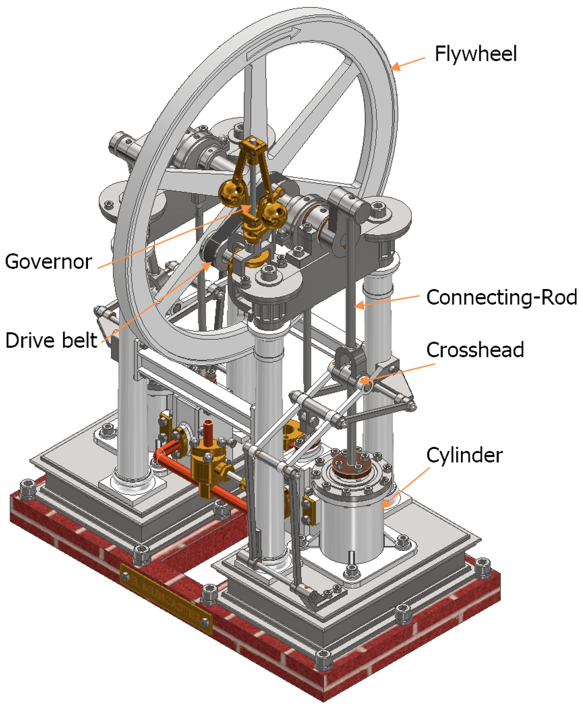
Figure 3.
Rear view of the 3D CAD model.

Figure 4.
Flowchart of the operation.

Figure 5.
Cross-section of the valve chest showing the slide valve: front view (left) and top view (right).
Figure 5.
Cross-section of the valve chest showing the slide valve: front view (left) and top view (right).

Figure 6.
Cross-section showing eccentric strap and eccentric sheave.

Figure 7.
Cross-section of both cylinders: steam intake (left) and steam exhaust (right).

Figure 8.
Cross-section of the ensemble showing the following elements: piston, rod, crosshead and connecting-rod.
Figure 8.
Cross-section of the ensemble showing the following elements: piston, rod, crosshead and connecting-rod.

Figure 9.
Necessary elements for parallel motion.

Figure 10.
Detailed view of the speed governor.

Figure 11.
Front view of the bevel gears linking the drive belt and the speed governor.

Figure 12.
Speed control system: front view (left) and rear view (right).

Figure 13.
Speed governor with all its elements.

Figure 14.
Steam supply control with all its elements.

Figure 15.
Top view of the throttle valve.

Figure 16.
Design of the governor vertical spindle: sketch (left) and front view of 3D model (right).
Figure 16.
Design of the governor vertical spindle: sketch (left) and front view of 3D model (right).

Figure 17.
Design of the upper flyweight arm support: (a) first step: sketch and extrude operation, (b) second step: sketch and removal operation and (c) third step: sketch and removal operation.
Figure 17.
Design of the upper flyweight arm support: (a) first step: sketch and extrude operation, (b) second step: sketch and removal operation and (c) third step: sketch and removal operation.

Figure 18.
Centering ring.

Figure 19.
Governor sliding collar: top view (left) and bottom view (right).

Figure 20.
Surface operation: bevel gear of the governor vertical spindle.

Figure 21.
Governor lower flyweight arm: sketch (left) and 3D model (right).

Figure 22.
Governor upper flyweight arm: sphere sketch (left) and 3D model (right).

Figure 23.
Pin for connection.

Figure 24.
Assembly of the governor vertical spindle and upper flyweight arm support: concentricity assembly operation.
Figure 24.
Assembly of the governor vertical spindle and upper flyweight arm support: concentricity assembly operation.

Figure 25.
Assembly of the governor vertical spindle and centering ring: concentricity assembly operation.
Figure 25.
Assembly of the governor vertical spindle and centering ring: concentricity assembly operation.

Figure 26.
Assembly of the governor vertical spindle and bevel gear: concentricity and leveling assembly operation.
Figure 26.
Assembly of the governor vertical spindle and bevel gear: concentricity and leveling assembly operation.

Figure 27.
Assembly of the governor vertical spindle and governor sliding collar: concentricity and leveling assembly operation.
Figure 27.
Assembly of the governor vertical spindle and governor sliding collar: concentricity and leveling assembly operation.
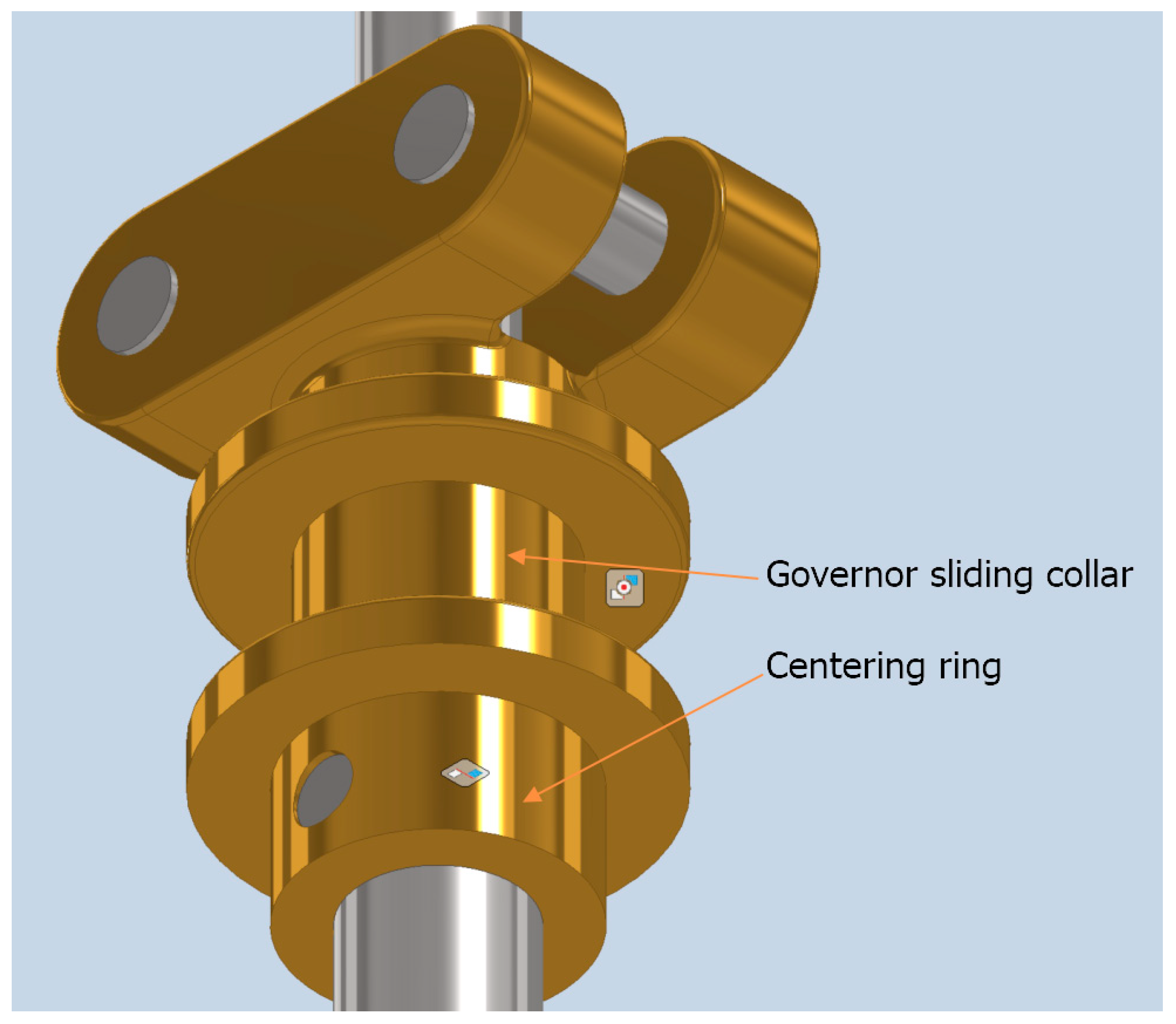
Figure 28.
Assembly of lower and upper flyweight arms with sliding collar and upper flyweight arm support: concentricity and leveling assembly operation.
Figure 28.
Assembly of lower and upper flyweight arms with sliding collar and upper flyweight arm support: concentricity and leveling assembly operation.

Figure 29.
First subassembly: speed governor.
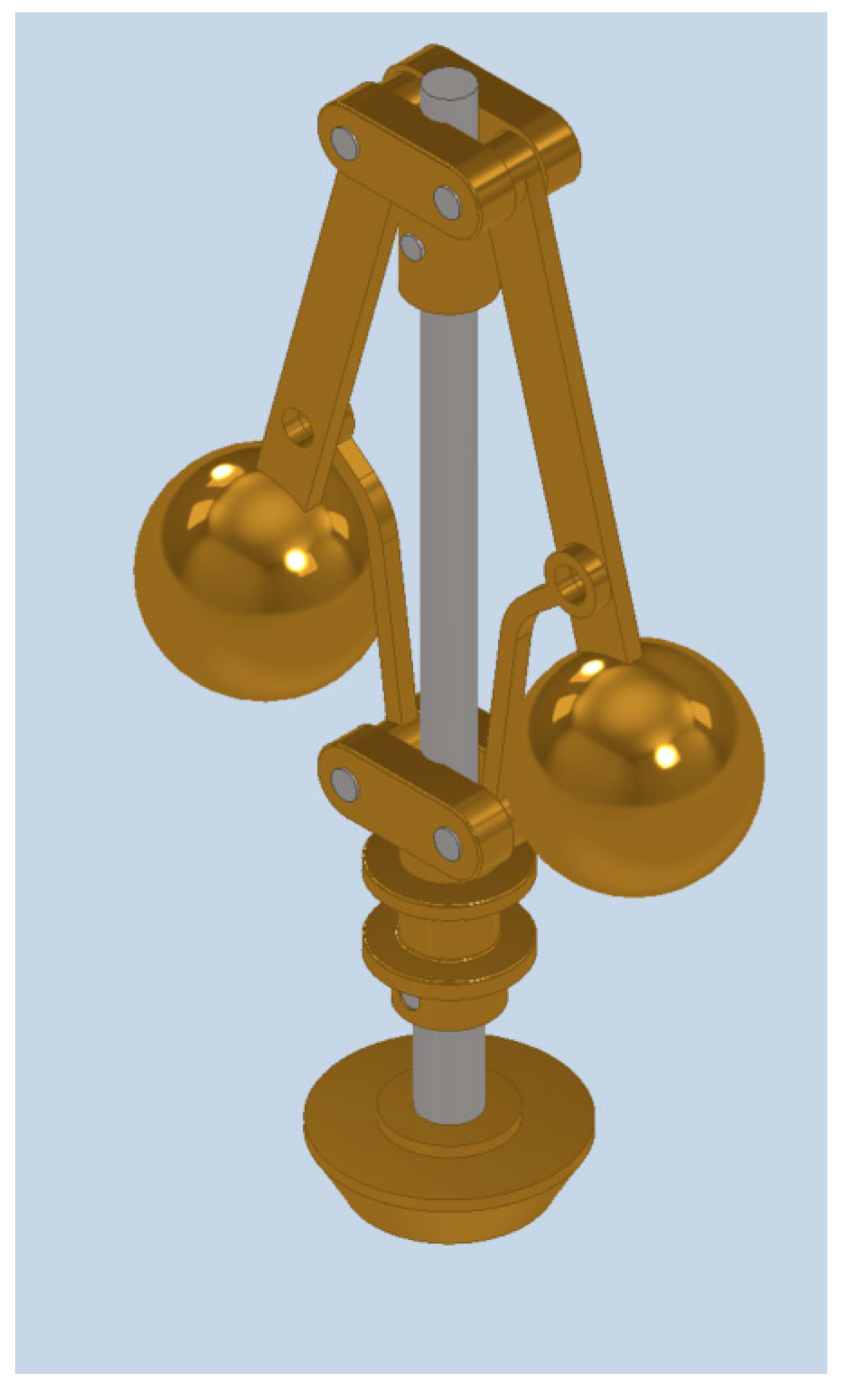
Figure 30.
Drive belt: sketch (left) and 3D model (right).

Figure 31.
Governor drive pulley (larger diameter): sketch (left) and 3D model (right).

Figure 32.
Governor drive pulley (smaller diameter).

Figure 33.
Bevel gear of the governor drive pulley.

Figure 34.
Spindle of the governor drive pulley: sketch (left) and 3D model (right).

Figure 35.
Governor drive pulley + gear: concentricity and leveling assembly operation.

Figure 36.
Assembly of the speed governor ensemble: (a) drive belt, (b) speed governor and (c) governor mounting bracket.
Figure 36.
Assembly of the speed governor ensemble: (a) drive belt, (b) speed governor and (c) governor mounting bracket.

Disclaimer/Publisher’s Note: The statements, opinions and data contained in all publications are solely those of the individual author(s) and contributor(s) and not of MDPI and/or the editor(s). MDPI and/or the editor(s) disclaim responsibility for any injury to people or property resulting from any ideas, methods, instructions or products referred to in the content. |
© 2024 by the authors. Licensee MDPI, Basel, Switzerland. This article is an open access article distributed under the terms and conditions of the Creative Commons Attribution (CC BY) license (https://creativecommons.org/licenses/by/4.0/).
Share and Cite
MDPI and ACS Style
Rojas-Sola, J.I.; Barranco-Molina, J.C. Engineering Drawing Applied to the Study of the Design of a Two-Cylinder Entablature Steam Engine with Parallel Motion Crosshead. Symmetry 2024, 16, 578. https://doi.org/10.3390/sym16050578
AMA Style
Rojas-Sola JI, Barranco-Molina JC. Engineering Drawing Applied to the Study of the Design of a Two-Cylinder Entablature Steam Engine with Parallel Motion Crosshead. Symmetry. 2024; 16(5):578. https://doi.org/10.3390/sym16050578
Chicago/Turabian StyleRojas-Sola, José Ignacio, and Juan Carlos Barranco-Molina. 2024. "Engineering Drawing Applied to the Study of the Design of a Two-Cylinder Entablature Steam Engine with Parallel Motion Crosshead" Symmetry 16, no. 5: 578. https://doi.org/10.3390/sym16050578
Note that from the first issue of 2016, this journal uses article numbers instead of page numbers. See further details here.