
High-Throughput Multi-Principal Element Alloy Exploration Using a Novel Composition Gradient Sintering Technique


Department of Chemical Engineering and Materials Science, University of Minnesota, Minneapolis, MN 55455, USA
*
Author to whom correspondence should be addressed.
Metals 2024, 14(5), 558; https://doi.org/10.3390/met14050558
Submission received: 1 April 2024
/
Revised: 22 April 2024
/
Accepted: 27 April 2024
/
Published: 9 May 2024
(This article belongs to the Special Issue Advances in Field-Assisted Processing of Metallic Materials: Experiments and Simulations)
Abstract
:This work demonstrates the capabilities and advantages of a novel sintering technique to fabricate bulk composition gradient materials. Pressure distribution calculations were used to compare several tooling geometries for use with current-activated, pressure-assisted densification or spark plasma sintering to densify a gradient along the long dimension of the specimen. The selected rectangular tooling design retains a low aspect ratio to ensure a uniform pressure distribution during consolidation by using a side loading configuration to form the gradient along the longest dimension. Composition gradients of NixCu1−x, MoxNb1−x, and MoNbTaWHfx (x from 0 to 1) were fabricated with the tooling. The microstructure, composition, and crystal structure were characterized along the gradient in the as-sintered condition and after annealing to partially homogenize the layers. The successful fabrication of a composition gradient in a difficult-to-process material like the refractory multi-principal element alloy system MoNbTaWHfx shows the utility of this approach for high-throughput screening of large material composition spaces.
1. Introduction
Functionally graded materials (FGMs), which are characterized by a spatial gradient in structure or composition, are of interest for a variety of technological applications. For instance, Wei et al. [1], Pintsuk et al. [2], and Zhou et al. [3] explored W-Cu gradients, and Tang et al. [4] explored W-V gradients to mitigate thermal stresses in plasma-facing nuclear applications. In balance with bulk mechanical properties like fatigue resistance, which was analyzed by Ghorbanpour et al. on graded IN718 [5], FGMs for aerospace applications must also display heat, oxidation, and corrosion resistance near the component surfaces, as mentioned in a review by Naebe and Shirvanimoghaddam [6]. This was demonstrated experimentally by Choi et al. [7] and Mohammadzadzki et al. [8] with graded YSZ thermal barrier coatings that functioned as heat shields, as well as by Naik et al. [9] with heat-resistant, graded ZrB2-B4C ultra-high temperature ceramic. Likewise, graded biomedical components can extend service lifetime through improved fracture toughness, as shown by Bahraminasab et al. [10] and Fujii et al. [11] with Ti-Al2O3 and Ti-TiH2 ceramic alloy composites. For all these applications, the gradient in composition or microstructure across the material leads to an advantageous change in properties, such as the increased number of interfaces from the gradients arresting thermal stress and fatigue cracks [5,11].
Compositionally graded materials (CGMs), a subset of FGMs, can also facilitate high-throughput screening of material compositions to support material discovery, as shown by Stewart et al. [12] with Co-based γ/γ′ alloys and by Wang et al. [13] with Ti6Al4V-TiC ceramic composites. In particular, CGMs are being employed to explore the composition space available to design multi-principal element alloys (MPEAs), as mentioned in a review by Ostovari Moghaddam et al. [14] and demonstrated with transition metal MPEAs by Pegues et al. [15]. These alloys, also known as high entropy alloys (HEAs) or compositionally complex alloys (CCAs), characteristically have four to six principal elements with concentrations ranging from 5 to 35 at% according to Miracle and Senkov [16]. MPEAs are of technical interest for a variety of applications based on their potential to achieve better combinations of strength and toughness [17,18] and oxidation and corrosion resistance [19,20], especially at higher temperatures. However, the large range of possible compositions combined with limitations in performance prediction models motivates the development of accelerated experimental synthesis methods.
A variety of techniques have been used to synthesize CGMs by either mixing components in the vapor phase or by blending pure elements or master alloy powders, followed by consolidation. Physical vapor deposition techniques, like the sputtering used by Nagy et al. [21] and Li et al. [22] on MPEAs or the ion-plasma deposition used by Stewart et al. [12], are widely used to fabricate compositionally graded ceramic and metal films but are less efficient for producing thick films. The production of thicker, millimeter-scale coatings via plasma spray has been explored by Pintsuk et al. [2] and Mohammadzadzki et al. [8], as well as by Malik and Kadoli on SUS316-Al2O3 composite CGM [23]. However, the coating must either be tested on or removed from the substrate, which limits some types of testing.
Bulk metal and composite CGMs have been additively manufactured using techniques such as laser-based direct energy deposition by Wang et al. [13], Dobbelstein et al. [24], and Gwalani et al. [25] to have discrete gradients, as well as by Borkar et al. [26], Chaudhary et al. [27], and Melia et al. [28] to have continuous gradients. However, to ensure proper densification and avoid vaporizing low melting point metals, Dobbelstein et al. [24], Borkar et al. [26], Melia et al. [28], and Moorehead et al. [29] all reported optimizing their powder flowrate, laser power, and scan speed through multiple trials, resulting in a time- and material-consuming process. Conversely, compaction and sintering-based approaches can offer a more straightforward powder-based approach for high-throughput screening of large composition spaces. Additionally, techniques such as current-activated, pressure-assisted densification (CAPAD) are well suited for rapid powder consolidation.
CAPAD, alternatively referred to as spark plasma sintering (SPS), compacts the material within an encasing die while simultaneously heating the material via a pulsed electric current applied through the die (see review by Garay [30] for more details). The technique can consolidate a variety of difficult-to-sinter materials, including refractory alloys, high-temperature ceramics, and composites, in a relatively short time at temperature. CGMs have historically been produced via CAPAD by loading thin layers of powders with different compositions through the cylindrical punch opening of the die. This approach produces a gradient along the shortest dimension of the sample and is often limited to five or six layers. The 0.3–1 mm thick layers produce a limited composition gradient length of up to 6 mm compared to the larger die diameter of up to at least 35 mm, as collectively reported by Zhou et al. [3], Tang et al. [4], Bahraminasab et al. [10], Fujii et al. [11], and Feng et al. [31]. Additionally, the conventional cylindrical geometry is not efficiently machined into the rectangular samples desired for many testing approaches. These limitations motivate the development of improved strategies to use CAPAD to fabricate CGMs for high-throughput screening.
This article explores a square CAPAD tooling design to fabricate CGMs with gradients along the longest dimension and perpendicular to the primary compaction direction. This geometry facilitates a more gradual change in composition and enables subsequent machining into multiple equivalent samples. To ensure comparable densification, attention is first given to compare the pressure distributions of possible designs for the new tooling to conventional, cylindrical tooling geometries. Model alloys in the Ni-Cu, Mo-Nb, and refractory MPEA space were then synthesized for NixCu1−x, MoxNb1−x, and MoNbTaWHfx with x from 0 to 1 along the direction of the gradient. The graded alloys were characterized in the as-sintered and annealed conditions to determine the capability to form continuous solid solutions, and the capabilities of CAPAD tooling for high-throughput exploration of various materials systems are discussed.
2. Design Approach
2.1. Geometry Pressure Distribution
During powder compaction, pressure gradients can develop within the compact due to friction with the die walls and non-uniform load transfer between particles. It is important to minimize these pressure gradients to ensure uniform densification. The normalized axial pressure experienced by a powder with a powder fluidity index of α compacted in cylindrical geometry with radius R, height H, and wall friction coefficient µ was described by Thompson [32] in terms of radial position r and depth into the compact z by assuming parabolic punch pressure with an average pressure P0 and constant central axis pressure C via Equation (1).
Similarly, the normalized axial pressure of rectangular geometry with a compression area of width W and length L can be described in terms of coordinates x and y via Equation (2).
These relationships were used to calculate and compare the expected pressure distributions in powder compacted in conventional double-action cylindrical die geometry with a 25 mm diameter and a range of filled heights (results for 5 mm height shown in Figure 1a–c) and rectangular geometry of 25 by 25 by 5 mm under two different loading orientations (Figure 1d–i). Following Thompson’s derivation, α and µ were set to 0.5 and 0.3, respectively, for all calculations.
Figure 1b,c shows that for standard cylindrical die geometry, the local pressure along the die wall at the specimen midplane, i.e., the position of the greatest frictional pressure dissipation, drops by ~10%. This modest pressure gradient is generally considered to be acceptable to achieve uniform compaction. Lengthening the gradient requires loading thicker or more layers, with a corresponding increase in the pressure gradient. For instance, increasing the loaded height, and thus the gradient length, to 25 mm (not shown) would produce a nearly 40% pressure differential within the sample, significantly reducing compaction uniformity. The resulting cylinder would be difficult to machine into rectangular samples for subsequent testing.
A die with a rectangular opening could alternatively be used to produce a long composition gradient with a more easily machinable configuration. However, if a 25 mm gradient is loaded along the primary compaction direction (Figure 1d), the local pressure in the outer corners of the sample would be ~40% higher than the average applied pressure. More significantly, there would be a ~60% drop in compaction pressure along the die wall at the center of the sample. The implication is that there would be significant variation in the degree of pressure-induced compaction throughout the final sample. However, if the composition gradient direction is rotated relative to the loading axis so that the rectangular geometry is compressed along its 5 mm thickness (Figure 1h), the minimum pressure is ~94% of the average applied pressure, reducing the pressure gradient to a level comparable to the conventional cylindrical geometry (Figure 1h,i). It is clear that by retaining the aspect ratio in the rectangular geometry, the pressure distribution in the powder is improved compared to the cylindrical geometry. However, despite the benefits of this compaction geometry, loading a perpendicular composition gradient through the primary die opening is not straightforward. This challenge motivated the current effort to develop new die geometry that is more viable for fabricating longer gradients via CAPAD.
2.2. Design Overview
Based on this modeling, tooling was designed for a 25 × 25 × 5 mm sintering volume that could be loaded orthogonally to the SPS compression axis (Figure 2a). For loading, the graphite tooling rests in a holder that holds the punches flush with the press so that the sintering volume is defined by the punch faces and die wall (Figure 2b). Alloy mixtures corresponding to each layer are sequentially loaded into the sintering volume through the plug opening, leveled, and cold pressed. After the final layer is added, the plug, outer sleeve, and pin are assembled, in that order, for sintering (Figure 2b,c). The outer sleeve secures the plug and provides added strength to the assembly at the expense of a larger cross-sectional area and reduced heating efficiency.
3. Materials and Methods
The new tooling design was used to produce graded bars of alloys based on NixCu1−x, MoxNb1−x, and MoNbTaWHfx for x from 0 to 1. Master alloys were prepared with high-energy planetary ball milling and the mixtures were prepared with roller milling prior to loading into the tooling, densifying via CAPAD, and annealing. The starting powders and densified and annealed gradient samples were characterized to assess the changes in the crystal structures, compositions, and local microstructures.
3.1. Powder Preparation
Copper (99% pure), nickel (99.5%), molybdenum (99.9%), niobium (99.5%), tantalum (99.95%), tungsten (99.9%), and hafnium (99.5% pure) powders with particle sizes less than 45 µm obtained from Beantown Chemical (Hudson, NH, USA) were used as starting materials. Master alloy powders corresponding to equimolar MoNbTaW and MoNbTaWHf were produced using planetary high-energy ball milling (Across International PQ-N04, Livingston, NJ, USA) to mix the elemental powders for 24 h at 600 rpm in tungsten carbide jars with tungsten carbide media (5:1 ball/powder by weight) and 3 wt% 200 proof ethanol in an argon atmosphere. Combinations of the pure elements (for NixCu1−x and MoxNb1−x) or the master alloy powders (for MoNbTaWHfx) were then combined to form mixtures for x = 0.11, 0.22, 0.33, 0.44, 0.56, 0.67, 0.78, and 0.89. The NixCu1−x and MoxNb1−x mixtures were milled for 2 h in ethanol with 304 stainless steel milling media on a roller mill (Peter Pugger, Ukiah, CA, USA) with a 1:3 ethanol/powder ratio. The MoNbTaWHfx compositions were milled (BTLab Systems Tube Roller, St. Louis, MO, USA) for 24 h in 3 wt% ethanol and tungsten carbide media in an argon glovebox. The ball-to-powder ratio was 10:1 by weight in both cases. After milling, the powder mixtures were dried and dispersed by grinding them with a mortar and pestle.
3.2. Sintering and Annealing Process
Initial consolidation process development was performed using the x = 0, 0.44, and 1 compositions. Each powder was first cold-pressed using a ½ ton arbor press to determine the green density, which aided in developing the loading plan for the gradient tooling. Separate samples were then sintered via CAPAD (Agus 0630Sx, Suga, Tokyo, Japan) in 10 mm diameter graphite tooling using different combinations of temperature, pressure, and time to identify CAPAD parameters to efficiently achieve high sintered density.
Powder mixtures were then loaded into the gradient tooling and cold pressed into 3.1 mm thick layers for the endmember compositions (x = 0 and 1) and 2.1 mm thick layers for the remaining compositions. A double-layer diffusion barrier comprising graphite foil against the graphite tooling and metal foil against the powder was used. Additional layers of the graphite foil (0.005″, CeraMaterials, Dingmans Ferry, PA, USA) were placed between the powder and plug after loading the final powder layer. Ni foil (0.1 mm, 99.5% pure, Thermo Scientific, Waltham, MA, USA) was used for NixCu1−x and Mo foil (0.127 mm, 99.95% pure, Eagle Alloys, Talbott, TN, USA) was used with the refractory metals.
The samples were sintered in a rough vacuum (0.2 Pa). The applied force was first ramped to apply 25 MPa to the sample during the first minute before heating at 100 °C/min to 900 °C for NixCu1−x or to 1900 °C for the refractory systems (Figure 3). The temperature measurement for the NixCu1−x samples used a K-type thermocouple inserted into a hole in the graphite die. For the refractory metals, a pyrometer was focused into a small hole drilled through the outer sleeve and into the inner die. Due to limitations of pyrometer measurement at low temperatures, the initial heating to 700 °C used manual power control. The samples were held for 10 min at the sintering temperature before cooling at 100 °C/min. The pressure was ramped down linearly over the cooling period.
After removing the samples from the dies, the diffusion barriers were ground from the surfaces and the square coupons were cut into strips along the gradient via wire electrical discharge machining (EDM). To further homogenize the samples, a NixCu1−x sample was annealed in a tube furnace (Protege XST, quartz tube, Thermocraft, Winston-Salem, NC, USA) at 1050 °C for 100 h in flowing, Ti-gettered Ar. The refractory metal samples were annealed in a furnace with a refractory metal hot zone (Oxy-Gon High Temperature 25 Ton Hot Press Vacuum Furnace System) at 1800 °C for 24 h with a flowing, Zr-gettered Ar atmosphere.
3.3. Characterization
Powder X-ray diffraction (XRD, Rigaku Miniflex 600) patterns were collected for the starting powders corresponding to x = 0, 0.44, and 1 and with a D8 Discover (Bruker, Madison, WI, USA) from points (~0.3 mm diameter illumination area) in each composition layer along the cross sections of the as-sintered and annealed samples. This focused XRD illumination in the D8 system provides the benefit of isolated analysis of each layer in the graded samples, but only samples a limited number of grains in the annealed samples.
The microstructures of the sintered and annealed samples were characterized using backscatter scanning electron microscopy (BS-SEM, SU8230, Hitachi, Schaumburg, IL, USA) and energy dispersive spectroscopy (EDS, Thermo Noran System 7 or X-Max, Oxford, Concord, MA, USA). Composition profiles along the ~25 mm length of the gradient were constructed based on the average compositions from a series of spectra collected from area scans for 100 µm wide fields of view centered every 150 µm along the gradient.
4. Results and Discussion
4.1. Starting Powders
Figure 4 shows XRD patterns for the endmembers and one representative intermediate mixture (x = 0.44) for each gradient. For the Ni-Cu system (Figure 4a), the patterns for the pure metals are consistent with the FCC reflections of Ni and Cu, respectively, and the Ni0.44Cu0.56 pattern shows reflections for both components. Likewise, the patterns for pure Mo and Nb (Figure 4b) are consistent with the expected BCC reflections, and the Mo0.44Nb0.56 pattern shows both sets of reflections. The alloy mixtures of the MoNbTaWHfx system (Figure 4c) produce reflections for the elemental constituents (BCC, except for the HCP Hf present for x = 0.44 and 1). Separate reflections corresponding to the lattice parameter for each metal component are evident, suggesting that there is limited mechanical alloying during milling (Figure 4c,d).
4.2. Cu-Ni Gradient Samples
Figure 5 shows a combination of SEM-EDS, XRD, and microstructure data for the as-sintered (AS) and annealed (An) NixCu1−x samples. Figure 5c,d shows BSE micrographs of two regions in the as-sintered sample located at the x = 0.78 to 0.67 and 0.56 to 0.44 transitions. The microstructure comprises lighter (Ni-rich) and darker (Cu-rich) regions with a characteristic length scale of order 10s of µm that likely corresponded to individual Ni and Cu powder particles that have fused during sintering. There is also a small fraction of fine (µm scale) porosity distributed throughout the sample. The overlaid points on Figure 5c,d, which show the average composition measured using EDS for each of the corresponding boxes, reveal local fluctuations in the composition depending on the fraction of Cu and Ni sampled at each location. Similar local fluctuations are present throughout the samples (blue line in Figure 5a). The composition steps between layers in the as-sintered gradient are more evident in the 3-point moving average shown in red in Figure 5a.
Figure 5b shows the XRD patterns collected at the center of each loaded composition labeled with black points in the EDS profiles. The patterns collected for layers near one of the endmembers, i.e., x = 0.11, 0.22, and 0.89, exhibit reflections with a small shift in d-spacing toward that of the minor component, indicating that the small fraction of the minor component partially dissolves into the primary component during sintering. Patterns for layers with intermediate values of x feature several peaks in the range of d-spacing between the values for the endmembers, representing varying degrees of local solution formation consistent with the microstructure observations.
Figure 5e,f shows representative microstructures of the NixCu1−x sample after annealing. The material exhibits uniform local greyscale contrast, suggesting solid solution formation that is expected with the annealing temperature close to the melting point of Cu. The porosity present in the as-sintered samples coalesces and coarsens during annealing, producing a smaller number density of larger (of order tens of µm) pores. The EDS area scans also produce a smoother profile than the as-sintered condition. The Cu-rich end of the specimen forms a nearly continuous uniform gradient, while the Ni-rich end shows uniform composition within layers and pronounced steps between the layers (Figure 5g) due to the higher Cu diffusivity [33]. After annealing, the XRD reflections sharpen to narrower, single peaks that uniformly shift in d-spacing with the layer composition, consistent with the solid solution and uniform gradient observed (Figure 5h). There is more variation in the relative intensities of (200) since the location-specific XRD characterization probes fewer grains in the annealed samples compared to conventional powder XRD.
4.3. Mo-Nb Gradient Samples
Figure 6 shows a combination of SEM-EDS, XRD, and microstructure data for the as-sintered (AS) and annealed (An) MoxNb1−x samples. Figure 6c shows a BSE micrograph near the center of the as-sintered sample. The microstructure is much coarser than the NixCu1−x, with fewer, larger pores with a characteristic length scale of order 10s of µm. Separate Mo- and Nb-rich regions cannot be distinguished using BSE signal due to their similar atomic masses, but the local fluctuations of the EDS area measurements along the gradient (blue line in Figure 6a) suggest an inhomogeneous microstructure like NixCu1−x. These fluctuations are the more pronounced between x = 0.33 and 0.78, and they may be influenced by the coarser microstructure, in which it is more common for the area scan to preferentially sample one or the other component. The coarser microstructure is likely due to the greater difference between the sintering temperature and metal melting points compared to the NixCu1−x gradient.
Figure 6b shows the XRD patterns collected at the center of each composition layer labeled with black points in the EDS profile. Like NixCu1−x, the patterns collected for layers near one of the endmembers, i.e., x = 0.11, 0.22, and 0.89, exhibit reflections with a small shift in d-spacing toward the partially dissolved minor component. The patterns for intermediate layers feature broad peaks corresponding to d-spacings between the values for the endmembers, representing varying degrees of local solution formation. The separation of (211) peaks at x = 0.33 and 0.78 further demonstrates the coarse, more segregated microstructure of the MoxNb1−x system. The small number of grains sampled by the localized XRD illumination area leads to inconsistent relative intensities between (200) and (211).
Figure 6d shows a representative microstructure near the center of the MoxNb1−x after annealing; little change in the microstructure is evident. The EDS area scans produce a smoother profile compared to the as-sintered condition (Figure 6e). The steps between layers are clear near the ends, while residual local fluctuations in the center indicate that while dissolution has occurred, there is not complete homogenization. After annealing, the XRD reflections coalesce into single peaks that uniformly shift in d-spacing based on the layer composition (Figure 6f). This further confirms the dissolution that occurs with annealing. However, it does not occur to the extent that the NixCu1−x gradient homogenizes due to the greater difference between the annealing and metal melting points in this system.
4.4. MoNbTaWHfx Gradient Samples
Figure 7 shows a combination of SEM-EDS, XRD, and microstructure data for the as-sintered (AS) and annealed (An) MoNbTaWHfx samples. The microstructure near the center of the as-sintered sample (Figure 7c) comprises lighter regions that are rich in either Hf, Ta, or W and darker regions that are rich in Mo or Nb. Based on the gradual changes in grayscale with a characteristic length of order 10s of µm, these regions likely correspond to individual powder particles that were fused together. There is also a small fraction of fine (µm scale) porosity distributed throughout the sample, as well as occasional HfO2 inclusions likely formed when Hf obtains oxygen from surface oxides and any dissolved oxygen in the powders. The EDS area scans reveal local fluctuations in Hf concentrations throughout the sample that only decrease in intensity near x = 0.11 and 0, where there is little Hf (blue line in Figure 7a). The composition steps between layers in the as-sintered gradient are more difficult to distinguish in the 3-point moving average shown in red compared to the previous compositions, likely due to complexity of the alloy matrix with higher melting point metals and the smaller composition steps of only 2.75 at% Hf between layers.
The XRD patterns collected at the center of each loaded composition (Figure 7b) generally feature several broad peaks in the range of d-spacing between the values for the constituents. This indicates varying degrees of local solution formation; it is consistent with the microstructure observations and similar to the MoxNb1−x system. The d-spacing increases with the concentration of the larger atomic radius Hf, indicating that Hf is dissolving into the local solution. The only indication of undissolved HCP Hf is the low intensity peak in the x = 1 layer.
The microstructure near the center of the MoNbTaWHfx sample after annealing (Figure 7d) appears mostly unchanged except for a slight increase in pore size. The EDS area scans produce similar composition fluctuations as the as-sintered condition, indicating little change in the degree of solution formation at a length scale greater than a few of the original particles (Figure 7e). Similarly, each XRD pattern features several broad peaks in the range of d-spacing between the values for constituents, with a gradual increase in d-spacing with Hf concentration (Figure 7f). The inclusion of the higher melting point metals Ta and W appears to lessen the homogenizing effect that was observed with the MoxNb1−x system.
4.5. Implications
The results show that it is difficult to achieve an extended composition gradient via powder compaction in conventional uniaxial tooling due to large variations in the pressure distribution within the die. Conversely, the new tooling geometry developed as part of this study enables the production of samples with the composition gradient along the long axis while minimizing pressure gradients during the subsequent CAPAD consolidation. This approach was demonstrated using composition gradients in the NixCu1−x, MoxNb1−x, and MoNbTaWHfx (x from 0 to 1) systems that were fully densified in rectangular geometry, using 10 loaded compositions to produce a stepped composition profile. However, it is a straightforward extension of the method to increase the number of discrete compositions and therefore reduce the magnitude of the composition steps between layers.
Due to the short time at temperature during consolidation, which is characteristic of CAPAD, the as-densified microstructures remained heterogeneous for the middle compositions of the binary gradients and the entirety of the five-component MPEA gradient. Efforts to promote solid solution formation within and between the composition steps in the gradient samples via annealing showed varying effectiveness. Complete dissolution only occurred in the NixCu1−x system, which was annealed just below the Cu melting point. However, even in that case, the degree of homogenization was not uniform along the length of the gradient, since increased diffusivity in the Cu-rich end of the gradient produced a nearly uniform gradient while the Ni-rich end of the sample retained discrete composition steps.
The two refractory alloy systems exhibited less solution formation since they were annealed at a lower homologous temperature. The MoxNb1−x system showed the most noticeable homogenization at the ends of the composition range where the minor solute element was able to dissolve into the primary component. Due to its increased number of elements, including the higher melting point Ta and W, annealing the MoNbTaWHfx alloy did not significantly change the microstructure aside from pore coalescence and growth similar to the other alloys. Higher annealing temperatures or the use of finer or pre-alloyed powder would improve the ability to produce a homogeneous microstructure and therefore the usefulness of this tooling for high-throughput exploration of MPEA compositions. A further unanticipated challenge was the pore growth observed during annealing. This phenomenon appears to be a common but underreported feature of CAPAD-processed materials that may arise when gases trapped in small, closed pores generated during consolidation expand during subsequent homogenization. Combining the synthesis approach with methods such as hot isostatic pressing (HIP) may help mitigate pore growth observed during annealing in this study.
5. Conclusions
Bulk compositionally graded materials are a useful means to screen large composition spaces, like those of MPEAs. CAPAD tooling was designed to be loaded from the side, such that the composition gradient was along the longest dimension and was validated by fabricating composition gradients of NixCu1−x, MoxNb1−x, and MoNbTaWHfx with x from 0 to 1. Key findings include the following:
- When considering various sample geometries for CAPAD, a high aspect ratio must be maintained to ensure proper pressure distribution through the powder pack. Thus, the rectangular tooling must be loaded from the side to form the composition gradient along the longest dimension.
- Upon densification via CAPAD, all alloy systems remained inhomogeneous due to the limited time at temperature, but the discrete loaded compositions could still be observed with EDS-area scans along the composition gradients.
- After subsequent annealing, the Ni-Cu gradient formed a uniform gradient, especially on the Cu-rich side with the lower melting point. Annealing improved the characterization of the Mo-Nb gradient, but it did not form a solid solution, and the MoNbTaWHfx gradient showed no change after annealing. For all systems, solutionizing came at the cost of pore growth.
Author Contributions
Conceptualization, B.L.B. and D.L.P.; methodology, B.L.B. and D.L.P.; validation, B.L.B.; formal analysis, B.L.B.; investigation, B.L.B.; writing—original draft preparation, B.L.B.; writing—review and editing, B.L.B. and D.L.P.; visualization, B.L.B.; supervision, D.L.P.; funding acquisition, B.L.B. and D.L.P. All authors have read and agreed to the published version of the manuscript.
Funding
This research was supported primarily by a NASA Space Technology Graduate Research Opportunities (NSTGRO) fellowship 80NSSC20K1166 and partially by the Office of Naval Research (ONR) award N00014-20-1-2732, monitored by Dr. David Shifler. Part of this work was carried out in the Characterization Facility at the University of Minnesota, which receives partial support from the NSF through the MRSEC (DMR-2011401) and the NNCI (ECCS-2025124) programs (Bruker D8 Discover). Other shared equipment used in this work was supported by NSF MRI DMR-1229263 (Hitachi SU8230).
Data Availability Statement
The raw data supporting the conclusions of this article will be made available by the authors on a reasonable request.
Conflicts of Interest
The authors declare no conflicts of interest. The funders had no role in the design of the study; in the collection, analyses, or interpretation of data; in the writing of the manuscript; or in the decision to publish the results.
References
- Wei, B.; Zhou, R.; Xu, D.; Chen, R.; Yu, X.; Cheng, P.; Cheng, J. Continuous WCu functional gradient material from pure W to WCu layer prepared by a modified sedimentation method. Nucl. Eng. Technol. 2022, 54, 4491–4498. [Google Scholar] [CrossRef]
- Pintsuk, G.; Brünings, S.E.; Döring, J.-E.; Linke, J.; Smid, I.; Xue, L. Development of W/Cu—Functionally graded materials. Fusion. Eng. Des. 2003, 66–68, 237–240. [Google Scholar] [CrossRef]
- Zhou, Z.-J.; Du, J.; Song, S.-X.; Zhong, Z.-H.; Ge, C.-C. Microstructural characterization of W/Cu functionally graded materials produced by a one-step resistance sintering method. J. Alloys Compd. 2007, 428, 146–150. [Google Scholar] [CrossRef]
- Tang, Y.; Qiu, W.; Chen, L.; Yang, X.; Song, Y.; Tang, J. Preparation of W–V functionally gradient material by spark plasma sintering. Nucl. Eng. Technol. 2020, 52, 1706–1713. [Google Scholar] [CrossRef]
- Ghorbanpour, S.; Sahu, S.; Deshmukh, K.; Borisov, E.; Riemslag, T.; Reinton, E.; Bertolo, V.; Jiang, Q.; Popovich, A.; Shamshurin, A.; et al. Effect of microstructure induced anisotropy on fatigue behaviour of functionally graded Inconel 718 fabricated by additive manufacturing. Mater. Charact. 2021, 179, 111350. [Google Scholar] [CrossRef]
- Naebe, M.; Shirvanimoghaddam, K. Functionally graded materials: A review of fabrication and properties. Appl. Mater. Today 2016, 5, 223–245. [Google Scholar] [CrossRef]
- Choi, K.H.; Kim, H.-S.; Park, C.H.; Kim, G.-H.; Baik, K.H.; Lee, S.H.; Kim, T.; Kim, H.S. High-temperature thermo-mechanical behavior of functionally graded materials produced by plasma sprayed coating: Experimental and modeling results. Met. Mater. Int. 2016, 22, 817–824. [Google Scholar] [CrossRef]
- Goudarzi, Z.M.; Valefi, Z.; Zamani, P. Effect of functionally graded structure design on durability and thermal insulation capacity of plasma-sprayed thick thermal barrier coating. Ceram. Int. 2021, 47, 34361–34379. [Google Scholar] [CrossRef]
- Naik, A.K.; Nazeer, M.; Prasad, D.K.V.D.; Laha, T.; Roy, S. Development of functionally graded ZrB2–B4C composites for lightweight ultrahigh-temperature aerospace applications. Ceram. Int. 2022, 48, 33332–33339. [Google Scholar] [CrossRef]
- Bahraminasab, M.; Ghaffari, S.; Eslami-Shahed, H. Al2O3-Ti functionally graded material prepared by spark plasma sintering for orthopaedic applications. J. Mech. Behav. Biomed. Mater. 2017, 72, 82–89. [Google Scholar] [CrossRef]
- Fujii, T.; Tohgo, K.; Iwao, M.; Shimamura, Y. Fracture toughness distribution of alumina-titanium functionally graded materials fabricated by spark plasma sintering. J. Alloys Compd. 2018, 766, 1–11. [Google Scholar] [CrossRef]
- Stewart, C.A.; Suzuki, A.; Pollock, T.M.; Levi, C.G. Rapid Assessment of Oxidation Behavior in Co-Based γ/γ′ Alloys. Oxid. Met. 2018, 90, 485–498. [Google Scholar] [CrossRef]
- Wang, F.; Mei, J.; Jiang, H.; Wu, X. Laser fabrication of Ti6Al4V/TiC composites using simultaneous powder and wire feed. Mater. Sci. Eng. A 2007, 445–446, 461–466. [Google Scholar] [CrossRef]
- Moghaddam, A.O.; Shaburova, N.A.; Samodurova, M.N.; Abdollahzadeh, A.; Trofimov, E.A. Additive manufacturing of high entropy alloys: A practical review. J. Mater. Sci. Technol. 2021, 77, 131–162. [Google Scholar] [CrossRef]
- Pegues, J.W.; Melia, M.A.; Puckett, R.; Whetten, S.R.; Argibay, N.; Kustas, A.B. Exploring additive manufacturing as a high-throughput screening tool for multiphase high entropy alloys. Addit. Manuf. 2021, 37, 101598. [Google Scholar] [CrossRef]
- Miracle, D.B.; Senkov, O.N. A critical review of high entropy alloys and related concepts. Acta Mater. 2017, 122, 448–511. [Google Scholar] [CrossRef]
- Diao, H.Y.; Feng, R.; Dahmen, K.A.; Liaw, P.K. Fundamental deformation behavior in high-entropy alloys: An overview. Curr. Opin. Solid. State Mater. Sci. 2017, 21, 252–266. [Google Scholar] [CrossRef]
- Yao, H.W.; Qiao, J.W.; Hawk, J.A.; Zhou, H.F.; Chen, M.W.; Gao, M.C. Mechanical properties of refractory high-entropy alloys: Experiments and modeling. J. Alloys Compd. 2017, 696, 1139–1150. [Google Scholar] [CrossRef]
- Birbilis, N.; Choudhary, S.; Scully, J.R.; Taheri, M.L. A perspective on corrosion of multi-principal element alloys. Npj Mater. Degrad. 2021, 5, 11. [Google Scholar] [CrossRef]
- Wang, Z.; Yan, Y.; Wu, Y.; Zhang, Y.; Zhao, X.; Su, Y.; Qiao, L. Recent research progress on the passivation and selective oxidation for the 3d-transition-metal and refractory multi-principal element alloys. Npj Mater. Degrad. 2023, 7, 86. [Google Scholar] [CrossRef]
- Nagy, P.; Rohbeck, N.; Widmer, R.N.; Hegedűs, Z.; Michler, J.; Pethö, L.; Lábár, J.L.; Gubicza, J. Combinatorial Study of Phase Composition, Microstructure and Mechanical Behavior of Co-Cr-Fe-Ni Nanocrystalline Film Processed by Multiple-Beam-Sputtering Physical Vapor Deposition. Materials 2022, 15, 2319. [Google Scholar] [CrossRef] [PubMed]
- Li, R.; Huang, T.; Zhang, J.; Jiang, C.; Zhang, Y.; Liaw, P.K. Microstructures, Mechanical Behavior, and Radiation Damage of (TiVCr)x-(TaW)1-x Binary System High-Entropy Alloy Films. Metals 2022, 12, 772. [Google Scholar] [CrossRef]
- Malik, P.; Kadoli, R. Nonlinear bending and free vibration response of SUS316-Al2O3 functionally graded plasma sprayed beams: Theoretical and experimental study. J. Vib. Control 2018, 24, 1171–1184. [Google Scholar] [CrossRef]
- Dobbelstein, H.; Gurevich, E.L.; George, E.P.; Ostendorf, A.; Laplanche, G. Laser metal deposition of compositionally graded TiZrNbTa refractory high-entropy alloys using elemental powder blends. Addit. Manuf. 2019, 25, 252–262. [Google Scholar] [CrossRef]
- Gwalani, B.; Gangireddy, S.; Shukla, S.; Yannetta, C.J.; Valentin, S.G.; Mishra, R.S.; Banerjee, R. Compositionally graded high entropy alloy with a strong front and ductile back. Mater. Today Commun. 2019, 20, 100602. [Google Scholar] [CrossRef]
- Borkar, T.; Chaudhary, V.; Gwalani, B.; Choudhuri, D.; Mikler, C.V.; Soni, V.; Alam, T.; Ramanujan, R.V.; Banerjee, R. A Combinatorial Approach for Assessing the Magnetic Properties of High Entropy Alloys: Role of Cr in AlCoxCr1–xFeNi. Adv. Eng. Mater. 2017, 19, 1700048. [Google Scholar] [CrossRef]
- Chaudhary, V.; Borkar, T.; Mikler, C.V.; Gwalani, B.; Choudhuri, D.; Soni, V.; Alam, T.; Ramanujan, R.V.; Banerjee, R. Additively Manufactured Functionally Graded FeNi based High Entropy Magnetic Alloys. In Proceedings of the 2018 IEEE International Magnetics Conference (INTERMAG), Singapore, 23–27 April 2018; p. 1. [Google Scholar] [CrossRef]
- Melia, M.A.; Whetten, S.R.; Puckett, R.; Jones, M.; Heiden, M.J.; Argibay, N.; Kustas, A.B. High-throughput additive manufacturing and characterization of refractory high entropy alloys. Appl. Mater. Today 2020, 19, 100560. [Google Scholar] [CrossRef]
- Moorehead, M.; Bertsch, K.; Niezgoda, M.; Parkin, C.; Elbakhshwan, M.; Sridharan, K.; Zhang, C.; Thoma, D.; Couet, A. High-throughput synthesis of Mo-Nb-Ta-W high-entropy alloys via additive manufacturing. Mater. Des. 2020, 187, 108358. [Google Scholar] [CrossRef]
- Garay, J.E. Current-Activated, Pressure-Assisted Densification of Materials. Annu. Rev. Mater. Res. 2010, 40, 445–468. [Google Scholar] [CrossRef]
- Feng, H.; Meng, Q.; Zhou, Y.; Jia, D. Spark plasma sintering of functionally graded material in the Ti–TiB2–B system. Mater. Sci. Eng. A 2005, 397, 92–97. [Google Scholar] [CrossRef]
- Thompson, A.R. Mechanics of powder pressing. I: Model for powder densification. Am. Ceram. Soc. Bull. 1981, 60, 237–243. [Google Scholar]
- Neumann, G.; Tuijn, C. Self-Diffusion and Impurity Diffusion in Pure Metals: Handbook of Experimental Data; Elsevier: Amsterdam, The Netherlands, 2011. [Google Scholar]
Figure 1.
(a) Cylindrical gradient geometry and its normalized pressure distribution maps in an (b) elevation and (c) plan view compared to the novel rectangular geometry, with the gradient along the longest dimension, under (d) axial and (g) transverse compression and the analogous normalized elevation and plan view pressure distribution maps ((e,f,h,i), respectively). The labels on the green planes in (a,d,g) refer to the cross sections shown in (b,c,e,f,h,i).
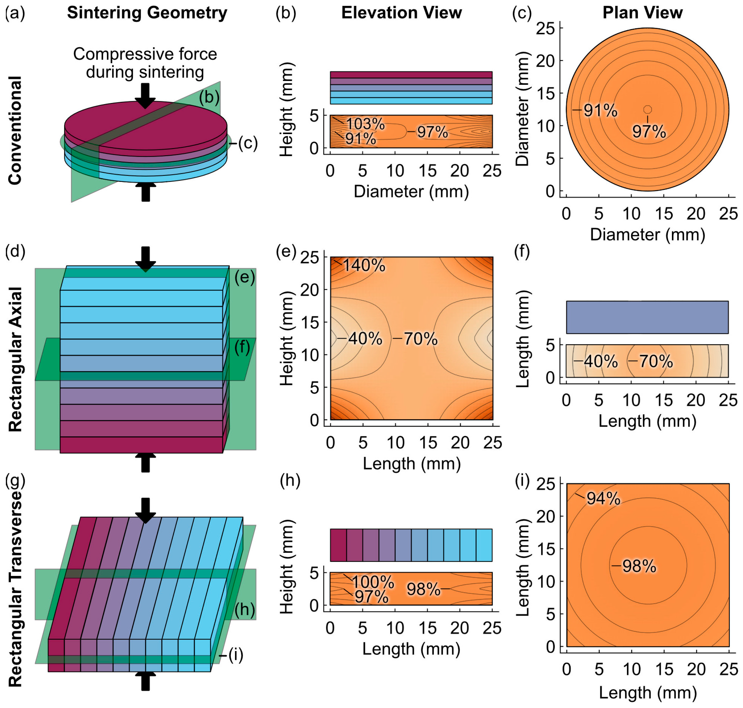
Figure 2.
(a) Renderings of the composition gradient tooling components and (b) photos of the components assembled while loading, after loading, and prior to sintering. (c) The gradient preparation steps of powder processing, loading, and sintering.
Figure 2.
(a) Renderings of the composition gradient tooling components and (b) photos of the components assembled while loading, after loading, and prior to sintering. (c) The gradient preparation steps of powder processing, loading, and sintering.
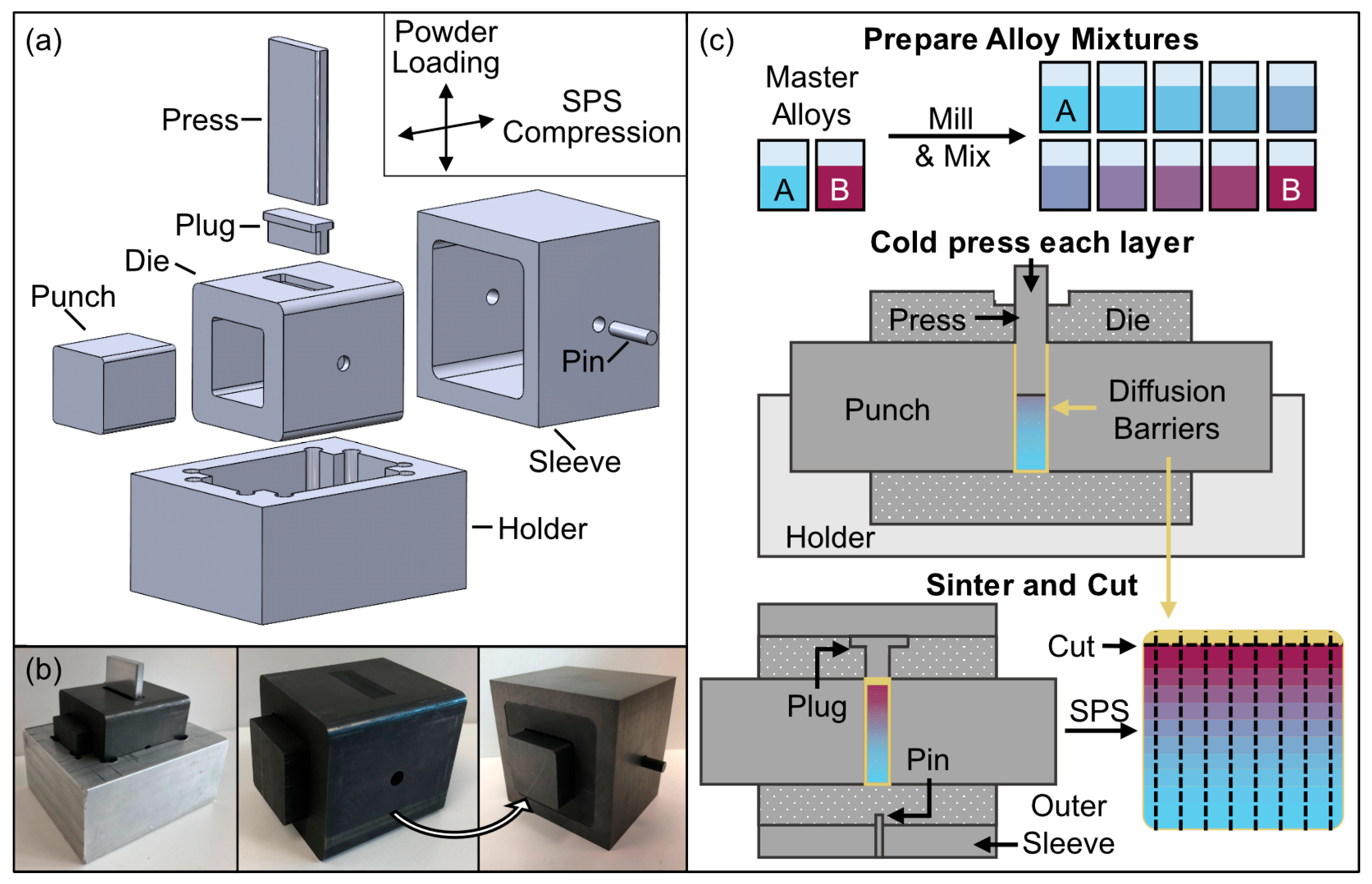
Figure 3.
The (a) temperature and (b) pressure profiles used for the sintering of NixCu1−x and the refractory MoxNb1−x and MoNbTaWHfx gradients.
Figure 3.
The (a) temperature and (b) pressure profiles used for the sintering of NixCu1−x and the refractory MoxNb1−x and MoNbTaWHfx gradients.

Figure 4.
X-ray diffraction patterns of master alloy compositions and the x = 0.44 mixture powders for the (a) NixCu1−x, (b) MoxNb1−x, and (c,d) MoNbTaWHfx alloy systems.
Figure 4.
X-ray diffraction patterns of master alloy compositions and the x = 0.44 mixture powders for the (a) NixCu1−x, (b) MoxNb1−x, and (c,d) MoNbTaWHfx alloy systems.

Figure 5.
(a) EDS and (b) XRD profiles of as-sintered NixCu1−x gradients. (c,d) BS-SEM micrographs marked with EDS scan areas (white boxes) and average Ni content (blue points) for two representative interfaces between layers in the as-sintered samples. (e,f) Micrographs of the same interfaces after annealing for 100 h at 1050 °C demonstrating increased homogeneity and smoother composition profile. All SEM images are on the same scale as (c). (g) EDS and (h) XRD profiles of the annealed NixCu1−x gradients.

Figure 6.
(a) EDS and (b) XRD profiles of as-sintered MoxNb1−x gradients. BS-SEM micrographs of the gradient (c) after sintering and (d) after annealing at 1800 °C for 24 h. Similar (e) EDS and (f) XRD profiles of the annealed MoxNb1−x gradients.
Figure 6.
(a) EDS and (b) XRD profiles of as-sintered MoxNb1−x gradients. BS-SEM micrographs of the gradient (c) after sintering and (d) after annealing at 1800 °C for 24 h. Similar (e) EDS and (f) XRD profiles of the annealed MoxNb1−x gradients.

Figure 7.
(a) EDS and (b) XRD profiles of as-sintered MoNbTaWHfx gradients. SEM micrographs of the gradient (c) after sintering and (d) after annealing at 1800 °C for 24 h. Similar (e) EDS and (f) XRD profiles of the annealed MoNbTaWHfx gradients.
Figure 7.
(a) EDS and (b) XRD profiles of as-sintered MoNbTaWHfx gradients. SEM micrographs of the gradient (c) after sintering and (d) after annealing at 1800 °C for 24 h. Similar (e) EDS and (f) XRD profiles of the annealed MoNbTaWHfx gradients.

Disclaimer/Publisher’s Note: The statements, opinions and data contained in all publications are solely those of the individual author(s) and contributor(s) and not of MDPI and/or the editor(s). MDPI and/or the editor(s) disclaim responsibility for any injury to people or property resulting from any ideas, methods, instructions or products referred to in the content. |
© 2024 by the authors. Licensee MDPI, Basel, Switzerland. This article is an open access article distributed under the terms and conditions of the Creative Commons Attribution (CC BY) license (https://creativecommons.org/licenses/by/4.0/).
Share and Cite
MDPI and ACS Style
Bresnahan, B.L.; Poerschke, D.L. High-Throughput Multi-Principal Element Alloy Exploration Using a Novel Composition Gradient Sintering Technique. Metals 2024, 14, 558. https://doi.org/10.3390/met14050558
AMA Style
Bresnahan BL, Poerschke DL. High-Throughput Multi-Principal Element Alloy Exploration Using a Novel Composition Gradient Sintering Technique. Metals. 2024; 14(5):558. https://doi.org/10.3390/met14050558
Chicago/Turabian StyleBresnahan, Brady L., and David L. Poerschke. 2024. "High-Throughput Multi-Principal Element Alloy Exploration Using a Novel Composition Gradient Sintering Technique" Metals 14, no. 5: 558. https://doi.org/10.3390/met14050558
Note that from the first issue of 2016, this journal uses article numbers instead of page numbers. See further details here.