Review

Innovations in Electric Current-Assisted Sintering for SOFC: A Review of Advances in Flash Sintering and Ultrafast High-Temperature Sintering

by
Jiajia Wu
,
Xiaohu Wu
,
Yan Gao
* and
Zilin Yan
*
School of Science, Harbin Institute of Technology, Shenzhen 518055, China
*
Authors to whom correspondence should be addressed.
Appl. Sci. 2024, 14(10), 3953; https://doi.org/10.3390/app14103953
Submission received: 15 March 2024 / Revised: 1 May 2024 / Accepted: 4 May 2024 / Published: 7 May 2024
(This article belongs to the Special Issue Materials Development and Potential Applications of Ceramics)

Abstract

:
This review discusses the groundbreaking advancements in electric current-assisted sintering techniques, specifically Flash Sintering (FS) and Ultrafast High-Temperature Sintering (UHS), for their application in Solid Oxide Fuel Cells (SOFCs). These innovative sintering methods have demonstrated remarkable potential in enhancing the efficiency and quality of SOFC manufacturing by significantly lowering sintering temperatures and durations, thereby mitigating energy consumption and cost. By providing a detailed overview of the mechanisms, process parameters, and material characteristics associated with FS and UHS, this paper sheds light on their pivotal role in the fabrication of SOFC components such as electrolytes, electrodes, multilayered materials, and interconnect coatings. The advantages, challenges, and prospective opportunities of these sintering technologies in propelling SOFC advancements are thoroughly assessed, underlining their transformative impact on the future of clean and efficient energy production technologies.

1. Introduction

With the development of human society, there is an increasing demand for energy. Fossil fuels, particularly coal, oil, and natural gas, remain the mainstay of the energy mix today [1]. However, the substantial quantity of carbon dioxide released by the heavy use of fossil fuels has caused significant harm to the environment, highlighting the urgent need to prioritize the advancement of power generation technologies that are both clean and efficient. Solid oxide fuel cells (SOFCs) are a very promising clean energy technology that effectively converts the chemical energy stored in fuel and oxidant gases into electricity [2,3,4,5], as shown in Figure 1. They exhibit many notable merits, such as high efficiency, ecological compatibility, a broad spectrum of fuel options, and the absence of the need for precious metal catalysts [6,7,8,9,10]. Given the current increasing energy demands, the importance of developing and implementing SOFCs is of utmost significance. SOFCs are widely recognized as the optimal option for future environmentally friendly power generation. Nonetheless, as SOFCs progress towards becoming commercially viable, they face obstacles related to maintaining stability over extended periods and managing the expenses associated with manufacturing. These issues arise from the necessity of running SOFC systems at high temperatures [11,12].
In order to address this difficulty, researchers have initiated the development of SOFCs that function at intermediate temperatures ranging from 500 to 800 °C [9,13,14,15]. The successful operation of SOFCs at intermediate temperatures depends not only on the advancement of electrolyte materials that exhibit excellent conductivity within this temperature range [16,17,18,19] but also on the utilization of thin-film electrolytes and nanostructured electrodes [20,21,22,23]. To achieve densification in SOFCs, electrode supports and high-temperature sintering exceeding 1400 °C are necessary for obtaining thin-film electrolytes. Nevertheless, this elevated temperature not only limits the melting point of other co-sintered materials, such as the metal supports used in SOFCs, but also hinders the achievement of electrode nanostructures. Hence, lowering the sintering temperature is advantageous for achieving thin-film electrolytes and nanostructured electrodes in SOFCs [24,25].
In order to reduce the sintering temperature of the electrolyte, researchers have investigated field-assisted sintering and current-assisted sintering techniques, resulting in the creation of various low-temperature sintering methods [26,27,28]. These sintering techniques not only reduce sintering temperatures but also significantly shorten the sintering durations. Some examples of sintering techniques include microwave sintering (MWS), spark plasma sintering (SPS), flash sintering (FS), and, more recently, ultrafast high-temperature sintering (UHS) [29,30,31,32,33,34,35]. Figure 2 displays the process sketches of several typical field-assisted and current-assisted sintering technologies. MWS uses the dielectric loss of ceramic materials in microwave electromagnetic fields to heat the materials to the sintering temperature, resulting in the sintering and densification of ceramics [36,37]. The SPS process predominantly employs the Joule heating effect induced by a pulsed direct current (DC), along with mechanical pressure exerted on the die. This die is heated by the Joule effect and subsequently transfers the heat to the material through conduction, swiftly raising its temperature and achieving densification [29,30,31,32]. Nevertheless, these two techniques encounter challenges when it comes to implementing a diverse array of industrial applications. This is due to their specific demands for sintering equipment and material types, as well as their limitations in terms of the size of the samples that can be sintered [38]. On the other hand, FS and UHS are innovative and more user-friendly techniques for ceramic densification.
FS, a technique developed in 2010 by Raj et al. at the University of Colorado, Boulder, involves use of an electric field while simultaneously heating the sample in a furnace [42]. UHS, developed in 2020 by Wang et al., employs carbon materials to encase ceramic green body samples [43]. This method quickly generates a consistent high-temperature setting by applying an electric field to the carbon material, resulting in extremely fast sintering in around 10 s [44,45]. Table 1 presents an overview of the key process characteristics, heating mechanism, advantages, and limitations associated with conventional sintering (CS) and alternative fast sintering techniques. The innovative current-assisted sintering techniques, such as FS and UHS, have several advantages in common. These include lower sintering temperatures, reduced processing times, and notable enhancements in material properties [46,47,48]. The purpose of this review is to provide a short summary of novel current-assisted sintering techniques (FS and UHS). Additionally, it seeks to summarize their developing history, delineate the most recent accomplishments, and identify the forthcoming problems in the field of SOFCs.

2. Flash Sintering

2.1. FS Process and Mechanism

Flash sintering was first documented for zirconia. This process is often accompanied by a flash of light. The initial study involved compacting 3 mol% yttria-stabilized zirconia (3YSZ) powder into a dog-bone shape, which was subsequently suspended within a heating furnace using two platinum wires attached to the dog-bone sample. A constant DC voltage was applied to the sample while it was heated at a constant rate. Rapid sintering occurred when the electric field intensity exceeded the critical value of 40 V/cm. With the rise in electric field intensity from 60 V/cm, there was a corresponding drop in the onset temperature of flash sintering. At an electric field strength of 120 V/cm, the 3YSZ sample could be sintered at a furnace temperature of 850 °C in a few seconds. Since the report, researchers have persistently engaged in discussions and investigations regarding the mechanism of FS; nevertheless, the exact mechanism remains controversial. The postulated mechanisms for this phenomenon based on experimental data and assumptions include:
  • Joule heating and the resulting local overheating of grain boundaries: The electrical current flowing through the sample can produce Joule heating, and particle-to-particle contacts at the grain boundaries can lead to high local temperatures [42,52,54,55].
  • Nucleation of Frenkel pairs: The applied electric field can promote the nucleation of Frenkel pairs (vacancies and interstitials) with opposite charges (one is a hole; the other is an electron). These pairs, when stripped of their charge by the electric field, become electrically neutral. As a result, they can move freely within the grain, migrate into grain boundaries and pores under the influence of sintering pressure, and thus contribute to sintering. Concurrently, the movement of holes and electrons generates an electric current that further promotes sintering [55,56,57,58].
  • The formation and rapid movement of oxygen vacancies: Under an electric field, the anodic reaction causes the formation of oxygen vacancies, which move rapidly from the anode to the cathode. The oxygen vacancies capture electrons, resulting in the partial reduction of the oxide and the transformation of the material into a mixed conductor with significantly enhanced conductivity [53,59,60,61].

2.2. The Application of FS in SOFCs

2.2.1. Electrolyte

In conventional sintering, electrolytes need to be exposed to high temperatures and kept for several hours to achieve a microstructure with closed pores [17]. These processes are not only costly in terms of energy and equipment expenses but also result in negative reactions with other components of the SOFC system [62]. Since Raj’s first report on the FS phenomenon of 3YSZ, where a DC field is applied for a few seconds at a furnace temperature of 850 °C, FS technology has been widely used for sintering SOFC electrolytes such as YSZ, gadolinium-doped ceria (GDC), BaZr0.1Ce0.7Y0.1Yb0.1O3 (BZCYYb), and La0.8Sr0.2Ga0.8Mg0.2O3 (LSGM) [63,64,65,66,67,68,69,70,71].
Cologna et al. [72] conducted a comprehensive study on the FS of 8YSZ, which has better conductivity compared to 3YSZ. The study demonstrated that the closed-porosity microstructure of 8YSZ could be achieved using FS at a reduced furnace temperature of 750 °C, which is 100 °C lower than the sintering temperature required for 3YSZ. The FS process for 8YSZ material was initiated at an electric field intensity of 30 V/cm, whereas 3YSZ required 60 V/cm. FS, with its low temperature and shortened sintering time, is advantageous in the production of SOFCs. It not only cuts costs but also mitigates the negative chemical interactions between zirconia and other constituents. In addition to the rapid densification achieved through FS, researchers are also concerned about its impact on dielectric properties. M’Peko et al. [73] compared the dielectric properties of flash-sintered and conventionally sintered 3YSZ samples. An electric field of 55 V/cm was applied at 900 °C. Once the current density reached 125 mA/mm2, the process switched to current control, which was maintained for 20–60 s. The results indicated that FS had only a slight impact on the sample’s conductivity and dielectric constant, but it significantly affected its grain boundary properties. Specifically, FS led to a 30% reduction in grain boundary thickness compared to conventionally sintered samples and increased the concentration of defects near these interfaces. Based on these findings, the authors proposed the following mechanism: a large number of defects in the space charge region nucleated with the assistance of the electric field, which increased grain boundary conductivity and promoted the sintering process. Consequently, the authors concluded that the impact of FS on the dielectric properties of materials is primarily reflected in the reduction of grain boundary semi-blocking properties.
Based on the previous research, Liu et al. [74] compared the effects of varying electric field strengths on the electrical properties of flash-sintered 3YSZ samples by measuring complex impedance spectra. The results, similar to those of conventional sintering, showed that FS leads to a decrease in grain boundary thickness. However, as electric field intensity increases, both the thickness and specific conductivity of grain boundaries increase. Specifically, when the current density is 110 mA/mm2 and the applied electric field is increased to 300 V/cm, the grain boundary thickness of the flash-sintered sample approaches that of the conventionally sintered sample. Additionally, experiments revealed an increase in the concentration of oxygen vacancies within the grains. Consequently, the authors proposed an alternative explanation based on the space charge layer model. The thickness of this layer depends not only on the concentration of oxygen vacancies within the layer but also on the concentration of oxygen vacancies in the grains. Assuming that the distribution of oxygen vacancy concentration remains constant and is independent of the concentration level, the thickness of the layer is proportional to the difference in concentration between the grain and the layer.
In the work conducted by Zhang et al. [75], 8YSZ samples were fabricated using current-restricted flash sintering (when the current reaches the set mark, the power supply switches from the voltage control stage to the current control stage). SEM images revealed that the microstructure exhibited a high level of density and a smaller grain size. Figure 3 displays the conductivity obtained from EIS analysis of the samples that were sintered at different isothermal furnace temperatures while being subjected to electric fields of 100 and 300 V/cm. Out of the samples, the one that was flash-sintered at a current density of 67 mA/mm2, under an electric field of 300 V/cm and a furnace temperature of 565 °C, showed a conductivity of 0.056 S/cm at 850 °C.
Aside from furnace temperature, the properties of flash-sintered materials are also affected by the intensity of the electric field. Mohebbi et al. [76] conducted a study on isothermal FS of 8YSZ at various electric field strengths ranging from 50–350 V/cm, with a maximum current density of 200 mA/mm2. They observed that the density of flash-sintered 8YSZ was not influenced by an electric field. Nevertheless, when subjected to an electric field strength of 350 V/cm, the crystal structure of 8YSZ underwent a phase change from cubic to tetragonal. FS improved the conductivity of 8YSZ in comparison to CS. The elevated concentration of oxygen vacancies in the flash-sintered samples has enhanced the conductivity at the grain boundaries. The conductivity of grain boundaries is determined by the space charge layer. The rapid increase in the concentration of oxygen vacancies in the space charge layer of flash-sintered samples enhances the conductivity of grain boundaries. In addition, the authors also listed another possible explanation that the formation of Frenkel defects reduces the activation energy required for grain conductivity. When subjected to an electric field of 80 V/cm, flash-sintered 8YSZ demonstrated a conductivity of 0.084 S/cm at a furnace temperature of 800 °C, while the conductivity of conventionally sintered samples was only 0.067 S/cm. The level of conductivity is suitable for its use as an SOFC electrolyte.
Zhang et al. [77] have shown that strip-shaped 20GDC specimens, which were compacted with a pressure of 470 Mpa, can be fully densified in just a few seconds at 545 °C using FS. They achieved this with an initial electric field strength of 20 V/cm, which is lower than the electric field strengths required for YSZ (30 V/cm for 8YSZ and 60 V/cm for 3YSZ) [72,78]. The power dissipation is 10 mW/mm3, which is the same as YSZ. As shown in Figure 4, as the magnitude of the external electric field increases, the grain size of GDC diminishes until it approximates the initial grain size of the raw material. The use of fine-grained GDC can enhance its mechanical performance as an SOFC electrolyte. The densification of electrolytes at low temperatures creates new possibilities and prospects for the advancement of nano-structured SOFC anode. Valdebenito et al. [79] applied FS to 10GDC tapes prepared by tape-casting and studied the influence of sintering parameters on the microstructure of the samples. The results showed that the initial electric field value required for FS of 10GDC is 100 V/cm, significantly higher than the critical electric field of 20GDC, reported as only 20 V/cm in previous studies. The authors hypothesized that the reason for this discrepancy may be the increased vacancy concentration, which reduces the critical electric field needed for FS to occur. Moreover, while the applied electric field influences the temperature at which FS takes place, it does not affect the densified structure of the sample. As the current density increases, so does the densification of the sample. For instance, under a constant electric field of 100 V/cm and with a current density of 220 mA/mm2 applied, a sample with 90% density can be achieved. Mishra et al. [80] conducted FS experiments on 10GDC under different atmospheres, namely air and Ar/5%H2. The results indicated that FS altered the electrical properties of GDC; the process activated n-type electrical conductivity associated with partial electrochemical reduction in GDC, and these changes were found to be partially retained after FS. Consequently, the authors proposed that the partial electrochemical reduction of the oxide, together with Joule heating, constitutes the triggering mechanism for the FS of GDC.
The application of SOFCs is limited by their operation at high temperatures, which highlights the importance of developing intermediate-temperature SOFCs as a significant trend [17,81]. In recent years, proton-conducting SOFCs (H+-SOFCs) have received significant attention for their ability to achieve high efficiency, high theoretical voltage, and low activation energy for conduction at medium to low operating temperatures [82,83]. BZCYYb, a potential electrolyte material for SOFCs, is known for its high proton conductivity and stability. However, achieving a relative density of 96% requires conventional sintering at 1550 °C for 15 h [71]. In a report by Jiang et al. [70], an improved DC sintering technique was proposed and applied to BZCYYb sintering, which involves limiting the current density to a certain value to adjust the sintering rate and extending the sintering time from seconds to an hour, as shown in Figure 5. When the electric field is 70 V/cm and the current density is 70 mA/mm2, this technique allowed for sintering at a lower furnace temperature of 850 °C for only one hour, resulting in full densification. Additionally, by controlling the current density and holding time, samples with the desired grain size could be obtained.
LSGM, although a promising electrolyte material for intermediate-temperature SOFCs, faces limitations in its sinterability, which prevents its wider application [84,85]. Sun et al. [69] employed current-restricted flash sintering to enhance the densification of LSGM, which restricts the electric current within a specific range and prolongs the duration of FS from a few seconds to several minutes or even hours. This process design mitigates concerns such as abrupt shrinkage, deformation, cracking, and other complications caused by current avalanches during flash sintering. At a current density of 90 mA/mm2 and an electric field strength of 100 V/cm, LSGM underwent FS at a furnace temperature of 690 °C, achieving a relative density of 97.4%. The material obtained at a furnace temperature of 800 °C had a conductivity of 0.049 S/cm, similar to that achieved through conventional sintering at 1400 °C. However, even when switched from voltage control to current control, sudden shrinkage still occurred and the power density increased significantly. Building upon the foundation of current-restricted flash sintering, Zhang et al. [86] proposed a stepwise current-limiting flash sintering technique (SCFS), which was successfully applied to the densification of LSGM. As illustrated in Figure 6, the current was initially set at 0.05 A and maintained for a duration of 100 s. Subsequently, it was increased to 0.1 A for a further 100 s, and this pattern continued until it reached the uppermost current limit of 1.3 A (the corresponding current density is 173 mA/mm2), which was maintained for 10 or 30 min. The findings demonstrated that LSGM samples, which were fabricated using a multi-step current-limiting FS technique, displayed enhanced density and a more homogeneous microstructure. Furthermore, their electrical conductivity was about equal to that of their conventionally sintered counterparts. SCFS exhibited exceptional controllability and has potential for utilization in large-scale SOFC manufacturing.

2.2.2. Anode

NiO-8YSZ composite materials are widely used as anode materials in SOFCs, and their conventional sintering requires temperatures ranging from 1400 to 1500 °C and several hours of incubation. FS can expedite the manufacturing process and lower production expenses. Bhandari et al. [87] employed FS to fabricate two distinct compositions of NiO-YSZ composites with varying NiO concentrations, utilizing two different sintering atmospheres. Sintering in air resulted in rapid densification within a few seconds, while sintering in a reducing atmosphere-conditioned FS resulted in the in-situ reduction of NiO to Ni metal but did not contribute to densification. Flash-sintered NiO-8YSZ composite anodes offer substantial energy and cost savings while allowing for the precise control of porosity through the manipulation of the electric parameters and sintering environment. Nevertheless, additional investigation and verification are necessary in order to comprehend their electrochemical and mechanical properties.
GDC exhibits higher conductivity than YSZ in the intermediate-temperature range [88,89]. Hence, NiO-GDC proves to be a more appropriate choice as an anode material for SOFCs operating at intermediate temperatures. Usuba et al. [90] effectively utilized the FS approach on NiO-GDC composite materials, which are extensively employed as anodes in intermediate-temperature SOFC. The researchers successfully achieved dense sintering of NiO-GDC at temperatures below 200 °C by applying an electric field of 50 V/cm and a current density of 260 mA/mm2. Flash-sintered NiO-GDC exhibited a notable enhancement in electrical conductivity compared to the conventionally sintered NiO-GDC mentioned in previous studies. Additionally, the electrical performance of flash-sintered NiO-GDC was found to be equal to that of conventionally sintered NiO-GDC samples sintered at 1500 °C. Nevertheless, the scientists stated that the current displayed preferential flow paths inside the samples instead of a uniform distribution, leading to different rates of shrinkage and causing microstructural non-uniformity.

2.2.3. Cathode

Lanthanum strontium cobalt ferrite (LSCF) is an essential cathode material for SOFCs due to its exceptional electrochemical catalytic and mixed ionic and electrical conductivity properties [91]. Gaur et al. [92] utilized FS on LSCF and exhibited that its high electrical conductivity enabled rapid sintering at furnace temperatures as low as 25–100 °C, with an electric field intensity ranging from 7.5–12.5 V/cm. Flash sintering, unlike conventional sintering, yields a uniform porous structure by manipulating specific parameters. Moreover, previous studies have confirmed that the addition of GDC to LSCF can improve polarization resistance and enhance cathode performance. In studies on FS of LSCF-GDC composites, LSCF underwent FS at temperatures as low as 45 °C under an electric field strength of 10 V/cm, while LSCF-GDC required 900 °C to initiate flash sintering. By adjusting the current density, it is possible to achieve a uniform porous structure that is well-suited for use in cathodic applications [93].

2.2.4. SOFC Multilayers

One of the key challenges in manufacturing SOFCs is the requirement for sintering processes that can achieve both densified electrolyte and porous electrode structures simultaneously [94,95]. Conventional co-sintering techniques often need high sintering temperatures, which promote densification but also lead to grain coarsening of the electrode structure [96,97]. Additionally, when co-sintering, the presence of stress mismatches across layers can result in deformation and delamination [98,99,100]. Therefore, there is a need for co-sintering methods that can function at reduced temperatures and shorter time periods, while simultaneously taking into account stress relief throughout the sintering process [101,102].
FS is a highly efficient process used to simultaneously sinter multiple layers of materials in SOFCs. The study conducted by Raj et al. [103] employed the FS technique to co-sinter multilayered materials, including an anode (a composite of YSZ and NiO) and an electrolyte (cubic zirconia). The results indicated that utilizing the FS technique at sintering temperatures lower than 1000 °C enabled the fabrication of samples that achieved electrolyte densification and anode porosity simultaneously. Furthermore, the FS technique effectively reduced and eliminated the cracks and delamination that are commonly caused by internal stresses during the conventional multilayer co-sintering process in SOFCs [104].
Liu et al. [105] introduced a novel sintering technique, the DC-assisted sintering technique (DC-AST), for fabricating NiO-YSZ|YSZ|LSM cells, as depicted in Figure 7. Previous studies have shown that 8YSZ can undergo fast sintering within seconds when exposed to a DC electric field of 150 V/cm at a furnace temperature of 750 °C [72]. However, when subjected to such elevated voltage and significant power usage, instantaneous shrinkage occurred, leading to uncontrollable collapse. The researchers postulated that the densification of the electrolyte film should occur gradually, making DC-assisted sintering techniques preferable. These techniques involve controlled, incremental, and moderate electrical currents. This approach has the benefit of preventing uncontrollable collapse. The article describes the effective fabrication of an anode with a suitable microstructure and a dense YSZ layer utilizing DC-assisted sintering at reduced temperatures. As shown in Figure 8, the grain size of DC-AST samples was only 440 nm. The constructed single cell demonstrated exceptional electrochemical performance, achieving maximum power densities of 0.8, 1.1, and 1.4 W/cm2 at temperatures of 650 °C, 700 °C, and 750 °C, respectively. The performance achieved through DC-assisted sintering surpassed that of conventional sintering, highlighting the potential effectiveness of DC-assisted sintering in the production of SOFCs.
The study conducted by Francis et al. [103] showed that multilayered materials consisting of a NiO-ZrO2 anode and a ZrO2 electrolyte layer could be flash-sintered in a few seconds at temperatures below a furnace temperature of 1000 °C. Figure 9 demonstrates that, unlike conventional sintering, there was a strong and seamless bonding between the anode and electrolyte layers, with no evidence of delamination. Under the effect of the electric field, the electrolyte and anode were connected in parallel, and the FS temperature of the multilayered material closely approached that of the anode layer. Moreover, the anode layer was responsible for the overall linear shrinkage rate of the multilayer. The FS process can be influenced by interactions between atoms and defects across different layers. Additionally, variations in the composition and structure of the multilayered material result in distinct electrical responses when subjected to an electric field. The FS behavior of multilayered materials cannot be simply predicted based on the behavior of individual layers. However, it is still highly effective in rapidly advancing the fabrication of SOFCs.
One of the main obstacles in the development of SOFC applications is dealing with carbon deposition [106,107]. The study conducted by Hao et al. [108] utilized FS to fabricate anode-supported SOFC single cells with La0.2Sr0.7TiO3 (LST), Ni and YSZ (LST-Ni/YSZ) gradient materials, which simultaneously possess coke resistance and high conductivity. As shown in Figure 10, the electrolyte layer, anode functional layer, cathode functional layer, and four anode support layers, A, B, C, and D (ASL-A, B, C, D), were securely fused together, preventing the deformation and delamination that is commonly experienced in conventional sintering methods. In contrast, with conventional sintering at a temperature of 1400 °C, the cell will deform toward the anode side because of the higher coefficient of thermal expansion of LST compared to NiO-YSZ. Prior to the electrolyte, the LST layer underwent densification, resulting in a porosity of less than 1%.
Muccillo et al. [109] utilized an AC electric field during the co-sintering process of a NiO-YSZ|YSZ|LSM single cell at a furnace temperature of 1200 °C. This led to a higher shrinkage rate of 26%, compared to the 15% achieved with conventional sintering. As shown in Figure 11, SEM images revealed that both the anode and cathode displayed a porous structure. The electrolyte is relatively dense, with some pores concentrated on the outer surface. FS resulted in a 63% reduction in the total electrical resistance of the single cell, as compared to conventional sintering.
GDC and LSCF are considered the most favorable electrolyte and cathode materials for SOFCs operating at intermediate temperatures [91]. Nevertheless, LSCF exhibits a significantly higher conductivity compared to GDC, with a difference of several orders of magnitude [93]. In order to address this problem, Ni et al. [110] employed FS to co-sinter LSCF/GDC bilayers. This research investigates the application of LSCF coatings of different lengths along the current direction, as shown in Figure 12. Specifically, only the LSCF in the GDC-LSCF-17 sample was electrically connected to the power source, while the LSCF in the other samples was detached from the power supply. The findings indicated that FS yielded tightly fused, dense GDC layers and porous LSCF layers, with a GDC density reaching 92.86% and an LSCF porosity of 52.26% observed in the GDC-LSCF-5 sample. The LSCF/GDC interface exhibited superior bonding and showed no signs of inadequate element diffusion or transverse cracks during the sintering process, in contrast to conventional sintering. This work successfully co-sintered multilayer ceramic materials with distinct conductivities using flash sintering. This approach offers a potential solution to address the issue of inconsistent sintering temperatures across different layers in multilayered materials for SOFCs.

2.2.5. Interconnect Coating

Interconnectors are vital elements that facilitate the passage of electric current between the cathodes and anodes of neighboring cells in SOFCs. In order to inhibit the corrosion of metal interconnects in both oxidizing and reducing conditions, ceramic coatings are often applied as protective layers [111]. Manganese cobalt oxide (Co2MnO4) exhibits a conductivity of 60 S/cm at 800 °C. This high conductivity makes it a highly suitable option for applying as a coating on interconnectors in SOFCs [112]. Conventional sintering processes usually require extended heating at a temperature of 1300 °C for several hours in order to achieve complete densification of Co2MnO4. However, Prette et al. [113] successfully accomplished FS of Co2MnO4 within seconds at a reduced furnace temperature of 325 °C by applying a DC field of 12.5 V/cm. To investigate the FS behavior of MnCo2O4 spinel, Gaur et al. [114] conducted a study indicating that MnCo2O4 can be rapidly sintered at temperatures between a furnace temperature of 120 °C and 150 °C using a voltage of 15.0 to 17.5 V/cm. This temperature range is significantly lower than the CS temperatures of over 1080 °C. Considering the microstructure, phase structure, and electrical conductivity, the author proposed that the mechanism of flash sintering in MnCo2O4 spinel is the natural ion rearrangement that occurs during flash accompanied by an increase in electrical conductivity. The authors have also elaborated on the local temperature range required for the sintering densification of the sample. This information is vital for the practical use of protective coatings in metal interconnects for SOFCs.
Compared to conventional sintering methods, FS offers numerous advantages in SOFC applications:
  • It accelerates the sintering process and lowers the sintering temperature, enabling ceramics to be processed together with metals or other materials;
  • It suppresses grain growth and satisfies the required mechanical properties;
  • It is a more straightforward and cost-effective alternative to conventional sintering.
However, the occurrence of hotspots and temperature gradients during the FS process poses a considerable challenge in attaining a consistent microstructure, hence impeding its industrial advancement to a great extent [115]. Consequently, FS has mostly been employed on small, rod-shaped samples in laboratory settings. It has been shown to be challenging to sinter larger samples with FS. In order to tackle the problem of uneven sintering, researchers have recently put forward other methods, such as incorporating small quantities of conductive phase, which have low activation energy, into the sample to increase the conductivity [116]. This helps to minimize temperature differences between the center and surface of the sample. Additional techniques include non-contact FS to avoid the need for direct contact between the electrode and sample, as well as multi-step current-limiting FS to regulate the flow of current and prevent the occurrence of localized high temperatures [117,118,119].

3. UHS

3.1. UHS Process and Mechanism

The classic high-temperature synthesis processes are commonly considered to be thermodynamically driven and operate continuously under equilibrium conditions [43,120]. This is a result of the gradual rates of heating and cooling. Consequently, products derived from conventional synthesis methods typically demonstrate the lowest Gibbs free energy and the most stable atomic configurations. To overcome the limitations imposed by thermodynamics in conventional high-temperature synthesis methods, researchers have redirected their attention toward materials synthesis techniques that are guided by kinetic principles [121]. There are two main methods for accomplishing this: one requires quickly creating high-temperature conditions within a short time frame, while the other permits materials to pass through a consistently hot area [122]. High-temperature Shock (HTS) synthesis is an innovative technique that utilizes the former approach and has the ability to achieve extremely rapid heating/cooling rates (>105 K s−1) [123]. Commonly used HTS techniques include Joule heating, laser heating, and microwave heating [124]. Hu et al. [43] introduced ultrafast high-temperature sintering (UHS), and they achieved successful sintering of alumina with a density of up to 96% and YSZ with a density exceeding 95% and a grain size of 265 ± 85 nm within seconds, as shown in Figure 13. This UHS method eliminates the need for pressure and effectively reduces the occurrence of side reactions. It has the ability to co-sinter various materials at the same time and sinter ceramic structures with complex geometries.
Since the report, researchers have persistently engaged in discussions and investigations concerning the mechanism of UHS. Based on experimental data and assumptions, the following mechanisms for the rapid sintering and densification of samples through UHS technology are proposed:
  • The passage of electric current through carbon cloth generates Joule heat, providing an ultra-high heating rate. This heat bypasses the low-temperature region, reducing particle coarsening and maintaining a high capillary driving force for sintering [43].
  • High sintering temperatures and rapid heating rates result in small particles with molten surfaces, which exhibit characteristics of rapid migration. This promotes grain rearrangement and accelerates densification [125].
  • The shorter processing time increases the number of defects, leading to a reduction in activation energy and an increase in conductivity, which in turn promotes sintering [126].

3.2. The Application of UHS in SOFCs

In recent years, researchers have started to investigate the utilization of UHS in the field of SOFCs. However, as this new technique was just invented recently, the majority of ongoing research is predominantly focused on the sintering of electrolyte materials.
Guo et al. [44] proposed that the carbon felt showed significant heat dissipation during the UHS heating process, and the measured temperature on the carbon felt surface was 200–250 °C lower than the actual temperature of the sample. This resulted in significant heat loss and impeded the densification of the sample. Dong et al. [127] addressed this problem by introducing a Thermally-insulated UHS (TI-UHS) process, as shown in Figure 14. This approach employed fiberboard insulation to limit the dissipation of heat in the carbon felt during the UHS sintering process. The TI-UHS method successfully produced a 99% dense and fine-grained 3YSZ within 60 s at 35 A, resulting in a 40% reduction in energy consumption compared to the UHS method. Wang et al. [128] synthesized 8YSZ by UHS and conducted a comparison with CS and FS. The findings demonstrated that UHS, as compared to CS, could attain a greater density of 8YSZ at the same sintering temperature and in a shorter duration. Additionally, the apparent activation energy for the densification of 8YSZ under UHS was lower than that under CS and FS.
Wu et al. [129] presented a new technique called UH-SPS, which combines the UHS and SPS techniques. This method utilizes tungsten wire heating instead of carbon felt. Translucent YSZ ceramics were effectively sintered utilizing UH-SPS, without experiencing problems such as blackening or carbon thermal reduction, which are typically observed when processing samples at temperatures above 1800 °C with carbon felt. Mattia et al. [130] utilized UHS to sinter 3YSZ nano-powder and prepared conventional sintered samples for comparison. Compared with conventionally sintered samples, 3YSZ processed by UHS exhibited a fine-grained structure, with the grain size reduced by more than 60% at an equivalent density. However, the grain boundary electrochemical response and the hardness of samples were found to be similar between UHS and conventionally sintered samples. The results indicate that UHS can refine the microstructure of the sintered body to a certain extent, yet it does not impact the hardness and grain boundary electrochemical properties. In addition, in order to examine the influence of static electric fields on YSZ sintering, the authors conducted conventional sintering both with and without the application of an electric field (where no current passed through the sample). The findings revealed that the electric field had only a minor effect on the microstructure and properties during sintering.
Alemayehu et al. [102] made an attempt to sinter GDC10 ceramics using UHS technology for the first time. Results revealed that modifying the heating profile of UHS to a multi-step gradient heating technique facilitated the efficient fabrication of GDC without any cracks or defects. The density achieved a level of 95%. In addition, a half-cell was prepared using GDC10 as the electrolyte and upper and lower LSF cathodes. The sintered electrolyte exhibited a high level of density, and no surface fractures were detected. Figure 15 illustrates a robust bonding between the electrode and the electrolyte interface with no evidence of delamination, indicating a significant potential of UHS for co-sintering multilayered materials in SOFCs.
Besides the electrolyte, there is also research showing the potential application of UHS in other materials for SOFCs. As shown in Figure 16, Guo et al. [131] applied UHS to a sinter cermet system composed using the Ni-based superalloy and YSZ, realizing high-density and homogeneous microstructures while minimizing the evaporation of Ni metal due to the reduced sintering time. The results demonstrated that the cermet composed of a Ni-based superalloy and YSZ, which was sintered using UHS, exhibited exceptional mechanical properties and high-temperature oxidation resistance. Furthermore, Guo et al. [132] investigated the application of UHS in the synthesis of LaCrO3 (LCO). As a promising interconnect material for SOFCs, due to its high melting point and exceptional stability at high temperatures, conventional sintering techniques typically require several tens of hours at high temperatures to achieve the desired density of LCO. Even with hot-press sintering, which reduces the time to two hours, prolonged holding times can result in Cr evaporation and increased energy consumption. The research findings indicate that the ultra-fast heating rate and extremely short sintering time of UHS promote the densification of LCO, which can reach 96%, while reducing the Cr evaporation.
The UHS equipment is characterized by its simplicity, user-friendly interface, and ability to achieve high heating rates and elevated maximum temperature thresholds, facilitating the densification of ceramics that are conventionally difficult to sinter. The UHS process is effectively managed through the precise regulation of current in order to control the heating rate and temperature. Importantly, unlike FS and SPS, UHS can conduct sintering on numerous samples at the same time and fabricate samples with complex forms. Although the present application of UHS in SOFCs is limited, it signifies a novel method for the fabrication and improvement of critical materials in SOFCs.

4. Current Progress and Other Applications

Taking YSZ, one of the most widely used and mature electrolyte materials, as an example, Table 2 compares UHS and FS with other sintering methods. It presents the density, grain size, and conductivity of YSZ samples obtained by different sintering techniques. Subsequently, Table 3 extends this comparison to GDC material, presenting similar comparative data for GDC samples obtained by the same array of sintering methods. In addition to the above advantages, fast sintering techniques such as FS and UHS can also reduce the loss of volatile elements and limit the interdiffusion of elements in multilayered materials. These aforementioned benefits render UHS and FS highly suitable for the advancement of key SOFC materials with great potential for practical use. It is worth noting that, in addition to FS and UHS, a recently proposed method known as electron-beam radiation-assisted synthesis has also emerged as a new avenue for ceramic synthesis. This method uses a powerful electron beam as a heater to sinter oxide powders, with a sintering duration of just 1 s [133,134]. Electron beam-assisted synthesis technology is both economical and efficient, and it holds significant potential for development and application in the field of SOFCs.
UHS and FS are innovative techniques for ceramic sintering that utilize electric current and have gained considerable interest in recent times. UHS enables the rapid synthesis and sintering of a variety of materials, with sintering temperatures up to 3000 °C achieved in an exceedingly short time frame. This feature is particularly beneficial when integrated with 3D printing technology, providing innovative approaches for creating complex geometries and developing new materials. For instance, UHS has been applied to 3D-printed 3YSZ components, specifically spiral-shaped disk components with a diameter of 10.1 mm and a thickness of 3.1 mm, for both thermal de-binding and densification processes [46]. This process is performed in a single step following the initial chemical degreasing phase. Additionally, researchers have proposed a novel Powder medium-based UHS approach (P-UHS) for heating spiral-shaped, honeycomb, and heat exchanger tube structure alumina samples, which are cylindrical in shape and have dimensions of Φ 9 mm × 9 mm. In the P-UHS setup, the sample is completely embedded in the graphite powder bed, the two electrodes are inserted into the graphite powder, and a DC power supply is connected. Similar to graphite felt, the graphite powder used in P-UHS effectively serves as both a heater and a thermal insulator [140]. It is demonstrated that UHS is indeed suitable for heating additively manufactured porous components.
Meanwhile, FS significantly reduces sintering time and temperatures by applying electrical fields and currents, and it improves material properties via the control of electrical parameters. Current efforts are focused on deepening the understanding of their underlying fundamental mechanisms, accelerating the research and development of new materials, enhancing energy efficiency, and merging with other cutting-edge technologies. For instance, contactless FS using cold plasma represents a scalable and energy-efficient sintering method [141], while Water-assisted Flash Sintering (WAFS) opens new pathways for low-temperature sintering [142]. Flash-SPS technology represents a densification method that achieves high heating rates under pressure, resulting in samples with superior mechanical and dielectric properties, including thinner grain boundaries, compared to those prepared by SPS [143]. Combining UHS with Reactive Cold Sintering (RCS) presents an effective method for producing highly dense and fine-grained MgAl2O4 ceramics [144].
UHS, despite its relatively nascent development, is already finding applications across various fields. It is currently utilized in the production of SOFC, solid electrolytes [145,146], polymer-derived ceramic nanocomposites (PDC-NC) [147], thermal barrier coating materials [41,148,149], thermoelectric nanomaterials [150], metal and alloy materials [151], biomaterials [152], and quartz glass [153], etc. FS, with its broad applicability, extends beyond SOFCs and solid electrolytes [154] to include semiconductor materials [55], metallic-like conductors such as borides, nitrides, and carbides of transition metals [113], armor [155,156], biomaterials [157,158], the joining of dissimilar materials [159,160], and nuclear fuel [161,162,163]. Notably, in the nuclear fuel sector, preliminary experiments have demonstrated the capability of FS technology to produce high-density nuclear fuels at significantly lower temperatures than those required for conventional sintering processes [161]. Although these two techniques have already had a considerable research foundation and have been used in the preparation of various materials, the sintering mechanisms of FS and UHS remain incompletely understood due to their relatively short period of development. Furthermore, the technology has not yet achieved mass production standards due to an immature process flow, high costs, and the need for improved product yield. In light of the ongoing worldwide environmental crisis, FS/UHS technology plays a significant role in promoting the development of SOFCs. However, additional research and investigations are necessary to meet practical requirements.

5. Challenges and Future Perspectives

Technical and Operational Challenges:
  • Process Control Precision: Achieving consistent and uniform outcomes with FS and UHS is complicated by the need for precise control over electric fields, temperature, and sintering atmosphere. This variability often results in non-uniform material properties, underscoring the need for advanced mechanistic insights and optimization strategies. Future research should aim to understand the physicochemical interactions and phase transformations during sintering, focusing on the dynamics of fast heating and cooling and the impact on material defects and microstructures under non-equilibrium conditions.
  • Material Compatibility and Diversity: Both FS and UHS encounter limitations with specific ceramics and composites, necessitating broader exploration of materials that are amenable to fast sintering processes without sacrificing structural integrity. Addressing this challenge involves developing new ceramic composites and coatings optimized for these sintering technologies, with enhanced ionic conductivities, mechanical properties, and thermal stabilities.
  • Scalability for Industrial Production: Scaling FS and UHS to industrial levels presents significant challenges, particularly in ensuring uniform treatment of larger or complex-shaped components and maintaining process stability. Investigating scalable sintering solutions that can adapt FS and UHS for large-scale manufacturing is crucial. Collaborative efforts between academia, industry, and equipment manufacturers are pivotal in this regard.
Equipment and Economic Considerations:
4.
Specialized Sintering Equipment: The requirement for advanced sintering systems capable of managing ultrafast heating rates and achieving high temperatures contributes to the cost and complexity of FS and UHS. Future pathways include the integration of these sintering techniques with additive manufacturing technologies, which could revolutionize SOFC component design and fabrication by enabling complex geometries and tailored microstructures for enhanced performance.
5.
Cost-Effectiveness and Energy Efficiency: The economic viability of FS and UHS in SOFC production hinges on balancing the initial investment in specialized equipment against the potential energy savings and improved efficiency from reduced sintering times. Emphasizing sustainable manufacturing practices that reduce the energy footprint of SOFC production aligns with global sustainability goals, urging further quantification of the environmental and economic impacts of these technologies.
Innovative Pathways for Technological Integration and Process Innovation:
6.
Synergy with other processes and hybrid sintering techniques: Exploring FS and UHS in conjunction with other emerging sintering technologies could provide balanced solutions to existing challenges. This approach promises uniform material properties, reduced thermal gradients, and improved densification outcomes, marking a transformative era for SOFC fabrication.

6. Conclusions

This review explores FS and UHS, which play a critical role in advancing SOFC technology. FS and UHS, as novel sintering methods, offer significant reductions in sintering time and temperature, marking a shift towards more efficient, less energy-intensive SOFC production and enabling innovative material and component designs.
Transitioning from lab to industry presents hurdles including process control, material compatibility, and scalability, highlighting the need for deeper mechanistic insights. Integrating these sintering techniques with other techniques could further revolutionize SOFC fabrication but requires overcoming technical and compatibility challenges.
Future research must focus on understanding sintering mechanisms, exploring FS and UHS integration with new materials, and enhancing process scalability and commercial feasibility. Such efforts could lead to efficient, cost-effective SOFC production, demanding collaboration among researchers, engineers, and industry players to exploit these technologies’ full potential, setting the stage for next-generation energy solutions.

Author Contributions

Conceptualization, Y.G.; investigation, J.W.; writing—original draft preparation, J.W. and X.W.; writing—review and editing, Z.Y. and Y.G.; supervision, Y.G.; project administration, Y.G.; funding acquisition, Z.Y. and Y.G. All authors have read and agreed to the published version of the manuscript.

Funding

This work was supported by the Guangdong Basic and Applied Basic Research Foundation (2023A1515010723), the National Natural Science Foundation of China (12172104), the Talent Recruitment Project of Guangdong (2021QN02L892), the Stable Supporting Fund of Shenzhen (GXWD20231130153335002), the Shccig-Qinling Program (SMYJY202300140C), the program of Innovation Team in Universities and Colleges in Guangdong (2021KCXTD006), and the Development and Reform Commission of Shenzhen (XMHT20220103004).

Institutional Review Board Statement

Not applicable.

Informed Consent Statement

Not applicable.

Data Availability Statement

Not applicable.

Conflicts of Interest

The authors declare no conflicts of interest.

References

  1. Jiang, S.P. Nanoscale and nano-structured electrodes of solid oxide fuel cells by infiltration: Advances and challenges. Int. J. Hydrogen Energy 2012, 37, 449–470. [Google Scholar] [CrossRef]
  2. Deepi, A.S.; Dharani Priya, S.; Samson Nesaraj, A.; Selvakumar, A.I. Component fabrication techniques for solid oxide fuel cell (SOFC)—A comprehensive review and future prospects. Int. J. Green Energy 2022, 19, 1600–1612. [Google Scholar] [CrossRef]
  3. Dziurdzia, B.; Magonski, Z.; Jankowski, H. Commercialisation of Solid Oxide Fuel Cells—Opportunities and forecasts. IOP Conf. Ser. Mater. Sci. Eng. 2016, 104, 012020. [Google Scholar] [CrossRef]
  4. Vinchhi, P.; Khandla, M.; Chaudhary, K.; Pati, R. Recent advances on electrolyte materials for SOFC: A review. Inorg Chem Commun 2023, 152, 110724. [Google Scholar] [CrossRef]
  5. Mohd Affandi, N.S.; Osman, N. Short review on global trends in SOFC scenario and future perspective. Mater. Today Proc. 2022, 66, 3981–3984. [Google Scholar] [CrossRef]
  6. Irshad, M.; Siraj, K.; Raza, R.; Ali, A.; Tiwari, P.; Zhu, B.; Rafique, A.; Ali, A.; Kaleem Ullah, M.; Usman, A. A Brief Description of High Temperature Solid Oxide Fuel Cell’s Operation, Materials, Design, Fabrication Technologies and Performance. Appl. Sci. 2016, 6, 75. [Google Scholar] [CrossRef]
  7. Mahato, N.; Banerjee, A.; Gupta, A.; Omar, S.; Balani, K. Progress in material selection for solid oxide fuel cell technology: A review. Prog. Mater. Sci. 2015, 72, 141–337. [Google Scholar] [CrossRef]
  8. Hussain, S.; Yangping, L. Review of solid oxide fuel cell materials: Cathode, anode, and electrolyte. Energy Transit. 2020, 4, 113–126. [Google Scholar] [CrossRef]
  9. Zhu, J.; Geng, S.; Ballard, D. Evaluation of several low thermal expansion Fe–Co–Ni alloys as interconnect for reduced-temperature solid oxide fuel cell. Int. J. Hydrogen Energy 2007, 32, 3682–3688. [Google Scholar] [CrossRef]
  10. Gu, H.; Chen, H.; Gao, L.; Zheng, Y.; Zhu, X.; Guo, L. Effect of Co doping on the properties of Sr0.8Ce0.2MnO3−δ cathode for intermediate-temperature solid-oxide fuel cells. Int. J. Hydrogen Energy 2008, 33, 4681–4688. [Google Scholar] [CrossRef]
  11. Kamalimeera, N.; Kirubakaran, V. Prospects and restraints in biogas fed SOFC for rural energization: A critical review in indian perspective. Renew. Sustain. Energy Rev. 2021, 143, 110914. [Google Scholar] [CrossRef]
  12. Kostogloudis, G. Chemical reactivity of perovskite oxide SOFC cathodes and yttria stabilized zirconia. Solid State Ion. 2000, 135, 529–535. [Google Scholar] [CrossRef]
  13. Wang, W.; Su, C.; Wu, Y.; Ran, R.; Shao, Z. Progress in solid oxide fuel cells with nickel-based anodes operating on methane and related fuels. Chem. Rev. 2013, 113, 8104–8151. [Google Scholar] [CrossRef]
  14. Saebea, D.; Authayanun, S.; Patcharavorachot, Y.; Arpornwichanop, A. Performance Evaluation of Low-Temperature Solid Oxide Fuel Cells with SDC-Based Electrolyte. Chem. Eng. Trans. 2016, 52, 223–228. [Google Scholar] [CrossRef]
  15. Leng, Y.; Chan, S.; Liu, Q. Development of LSCF–GDC composite cathodes for low-temperature solid oxide fuel cells with thin film GDC electrolyte. Int. J. Hydrogen Energy 2008, 33, 3808–3817. [Google Scholar] [CrossRef]
  16. Steele, B. Material science aspects of SOFC technology with special reference to anode development. Solid State Ion. 1990, 40–41, 388–393. [Google Scholar] [CrossRef]
  17. Choy, K.; Bai, W.; Charojrochkul, S.; Steele, B.C.H. The development of intermediate-temperature solid oxide fuel cells for the next millennium. J. Power Sources 1998, 71, 361–369. [Google Scholar] [CrossRef]
  18. Milliken, C.; Guruswamy, S.; Khandkar, A. Evaluation of Ceria Electrolytes in Solid Oxide Fuel Cells Electric Power Generation. J. Electrochem. Soc. 2019, 146, 872–882. [Google Scholar] [CrossRef]
  19. Maric, R.; Ohara, S.; Fukui, T.; Yoshida, H.; Nishimura, M.; Inagaki, T.; Miura, K. Solid Oxide Fuel Cells with Doped Lanthanum Gallate Electrolyte and LaSrCoO3 Cathode, and Ni-Samaria-Doped Ceria Cermet Anode. J. Electrochem. Soc. 2019, 146, 2006–2010. [Google Scholar] [CrossRef]
  20. Hibino, T.; Tsunekawa, H.; Tanimoto, S.; Sano, M. Improvement of a Single-Chamber Solid-Oxide Fuel Cell and Evaluation of New Cell Designs. J. Electrochem. Soc. 2000, 147, 1338. [Google Scholar] [CrossRef]
  21. Doshi, R.; Richards, V.L.; Carter, J.D.; Wang, X.; Krumpelt, M. Development of Solid-Oxide Fuel Cells That Operate at 500 °C. J. Electrochem. Soc. 2019, 146, 1273–1278. [Google Scholar] [CrossRef]
  22. Park, S.; Vohs, J.M.; Gorte, R.J. Direct oxidation of hydrocarbons in a solid-oxide fuel cell. Nature 2000, 404, 265–267. [Google Scholar] [CrossRef] [PubMed]
  23. Ding, J.; Liu, J. An anode-supported solid oxide fuel cell with spray-coated yttria-stabilized zirconia (YSZ) electrolyte film. Solid State Ion. 2008, 179, 1246–1249. [Google Scholar] [CrossRef]
  24. Sındıraç, C.; Çakırlar, S.; Büyükaksoy, A.; Akkurt, S. Lowering the sintering temperature of solid oxide fuel cell electrolytes by infiltration. J. Eur. Ceram. Soc. 2019, 39, 409–417. [Google Scholar] [CrossRef]
  25. Shri Prakash, B.; Pavitra, R.; Senthil Kumar, S.; Aruna, S.T. Electrolyte bi-layering strategy to improve the performance of an intermediate temperature solid oxide fuel cell: A review. J. Power Sources 2018, 381, 136–155. [Google Scholar] [CrossRef]
  26. Grasso, S.; Sakka, Y.; Maizza, G. Electric current activated/assisted sintering (ECAS): A review of patents 1906-2008. Sci. Technol. Adv. Mater. 2009, 10, 053001. [Google Scholar] [CrossRef]
  27. Orrù, R.; Licheri, R.; Locci, A.M.; Cincotti, A.; Cao, G. Consolidation/synthesis of materials by electric current activated/assisted sintering. Mater. Sci. Eng. R. Rep. 2009, 63, 127–287. [Google Scholar] [CrossRef]
  28. Munir, Z.A.; Anselmi-Tamburini, U.; Ohyanagi, M. The effect of electric field and pressure on the synthesis and consolidation of materials: A review of the spark plasma sintering method. J. Mater. Sci. 2006, 41, 763–777. [Google Scholar] [CrossRef]
  29. Nygren, M.; Shen, Z. On the preparation of bio-, nano- and structural ceramics and composites by spark plasma sintering. Solid State Sci. 2003, 5, 125–131. [Google Scholar] [CrossRef]
  30. Mamedov, V. Spark plasma sintering as advanced PM sintering method. Powder Metall. 2013, 45, 322–328. [Google Scholar] [CrossRef]
  31. Guillon, O.; Gonzalez-Julian, J.; Dargatz, B.; Kessel, T.; Schierning, G.; Räthel, J.; Herrmann, M. Field-Assisted Sintering Technology/Spark Plasma Sintering: Mechanisms, Materials, and Technology Developments. Adv. Eng. Mater. 2014, 16, 830–849. [Google Scholar] [CrossRef]
  32. Groza, J.R.; Zavaliangos, A. Sintering activation by external electrical field. Mater. Sci. Eng. A 2000, 287, 171–177. [Google Scholar] [CrossRef]
  33. Guillon, O.; Rheinheimer, W.; Bram, M. A Perspective on Emerging and Future Sintering Technologies of Ceramic Materials. Adv. Eng. Mater. 2023, 25, 2201870. [Google Scholar] [CrossRef]
  34. Demirskyi, D.; Vasylkiv, O. Hot-spots generation, exaggerated grain growth and mechanical performance of silicon carbide bulks consolidated by flash spark plasma sintering. J. Alloys Compd. 2017, 691, 466–473. [Google Scholar] [CrossRef]
  35. Xu, J.K.; Liu, Z.T.; Xie, Z.P.; He, S.; Xi, X.Q. DC electric field-assisted hot pressing of zirconia: Methodology, phenomenology, and sintering mechanism. J. Am. Ceram. Soc. 2021, 104, 5571–5583. [Google Scholar] [CrossRef]
  36. Alem, S.A.A.; Latifi, R.; Angizi, S.; Hassanaghaei, F.; Aghaahmadi, M.; Ghasali, E.; Rajabi, M. Microwave sintering of ceramic reinforced metal matrix composites and their properties: A review. Mater. Manuf. Process. 2020, 35, 303–327. [Google Scholar] [CrossRef]
  37. Oghbaei, M.; Mirzaee, O. Microwave versus conventional sintering: A review of fundamentals, advantages and applications. J. Alloys Compd. 2010, 494, 175–189. [Google Scholar] [CrossRef]
  38. Kermani, M.; Hu, C.; Grasso, S. From pit fire to Ultrafast High-temperature Sintering (UHS): A review on ultrarapid consolidation. Ceram. Int. 2023, 49, 4017–4029. [Google Scholar] [CrossRef]
  39. Biesuz, M.; Grasso, S.; Sglavo, V.M. What’s new in ceramics sintering? A short report on the latest trends and future prospects. Curr. Opin. Solid State Mater. Sci. 2020, 24, 100868. [Google Scholar] [CrossRef]
  40. Wang, R.H.; Yang, J.; Zou, D.N.; Hu, P.; Xiang, W.C. Recent Progress on Microwave Sintering of Metal Materials. Mater. Rep. 2021, 35, 23153–23161+23170. (In Chinese) [Google Scholar]
  41. Ye, F.X.; Meng, F.W.; Luo, T.Y.; Qi, H. Ultrafast high-temperature sintering of (Y0.2Dy0.2Er0.2Tm0.2Yb0.2)4Hf3O12 high-entropy ceramics with defective fluorite structure. J. Eur. Ceram. Soc. 2022, 42, 4686–4691. [Google Scholar] [CrossRef]
  42. Cologna, M.; Rashkova, B.; Raj, R. Flash Sintering of Nanograin Zirconia in <5 s at 850 °C. J. Am. Ceram. Soc. 2010, 93, 3556–3559. [Google Scholar] [CrossRef]
  43. Wang, C.; Ping, W.; Bai, Q.; Cui, H.; Hensleigh, R.; Wang, R.; Brozena, A.H.; Xu, Z.; Dai, J.; Pei, Y.; et al. A general method to synthesize and sinter bulk ceramics in seconds. Science 2020, 368, 521–526. [Google Scholar] [CrossRef]
  44. Guo, R.-F.; Mao, H.-R.; Zhao, Z.-T.; Shen, P. Ultrafast high-temperature sintering of bulk oxides. Scr. Mater. 2021, 193, 103–107. [Google Scholar] [CrossRef]
  45. Kermani, M.; Dong, J.; Biesuz, M.; Linx, Y.; Deng, H.; Sglavo, V.M.; Reece, M.J.; Hu, C.; Grasso, S. Ultrafast high-temperature sintering (UHS) of fine grained α-Al2O3. J. Eur. Ceram. Soc. 2021, 41, 6626–6633. [Google Scholar] [CrossRef]
  46. Bhandari, S.; Manière, C.; Sedona, F.; De Bona, E.; Sglavo, V.M.; Colombo, P.; Fambri, L.; Biesuz, M.; Franchin, G. Ultra-rapid debinding and sintering of additively manufactured ceramics by ultrafast high-temperature sintering. J. Eur. Ceram. Soc. 2024, 44, 328–340. [Google Scholar] [CrossRef]
  47. Behera, R.P.; Reavley, M.J.-H.; Du, Z.; Gan, C.L.; Le Ferrand, H. Ultrafast high-temperature sintering of dense and textured alumina. J. Eur. Ceram. Soc. 2022, 42, 7122–7133. [Google Scholar] [CrossRef]
  48. Wu, J.; Lin, Y.; Kermani, M.; Hu, C.; Grasso, S. Ultra-fast high temperature sintering (UHS) of Li1.5Al0.5Ge1.5P3O12 electrolyte: A rationalization of the heating schedule. Ceram. Int. 2022, 48, 6356–6362. [Google Scholar] [CrossRef]
  49. Dancer, C.E.J. Flash sintering of ceramic materials. Mater. Res. Express 2016, 3, 102001. [Google Scholar] [CrossRef]
  50. Mishra, R.R.; Sharma, A.K. Microwave–material interaction phenomena: Heating mechanisms, challenges and opportunities in material processing. Compos. Part A Appl. Sci. Manuf. 2016, 81, 78–97. [Google Scholar] [CrossRef]
  51. Li, X.Y.; Zhang, Z.H.; Cheng, X.W.; Huo, G.J.; Zhang, S.Z.; Song, Q. The Development and Application of Spark Plasma Sintering Technique in Advanced Metal Structure Materials: A Review. Powder Metall. Met. Ceram. 2021, 60, 410–438. [Google Scholar] [CrossRef]
  52. Yu, M.; Grasso, S.; McKinnon, R.; Saunders, T.; Reece, M.J. Review of flash sintering: Materials, mechanisms and modelling. Adv. Appl. Ceram. 2016, 116, 24–60. [Google Scholar] [CrossRef]
  53. Biesuz, M.; Sglavo, V.M. Flash sintering of ceramics. J. Eur. Ceram. Soc. 2019, 39, 115–143. [Google Scholar] [CrossRef]
  54. Todd, R.I.; Zapata-Solvas, E.; Bonilla, R.S.; Sneddon, T.; Wilshaw, P.R. Electrical characteristics of flash sintering: Thermal runaway of Joule heating. J. Eur. Ceram. Soc. 2015, 35, 1865–1877. [Google Scholar] [CrossRef]
  55. Cologna, M.; Francis, J.S.C.; Raj, R. Field assisted and flash sintering of alumina and its relationship to conductivity and MgO-doping. J. Eur. Ceram. Soc. 2011, 31, 2827–2837. [Google Scholar] [CrossRef]
  56. Raj, R.; Cologna, M.; Francis, J.S.C. Influence of Externally Imposed and Internally Generated Electrical Fields on Grain Growth, Diffusional Creep, Sintering and Related Phenomena in Ceramics. J. Am. Ceram. Soc. 2011, 94, 1941–1965. [Google Scholar] [CrossRef]
  57. Raj, R. Joule heating during flash-sintering. J. Eur. Ceram. Soc. 2012, 32, 2293–2301. [Google Scholar] [CrossRef]
  58. Francis, J.S.C.; Raj, R. Flash-Sinterforging of Nanograin Zirconia: Field Assisted Sintering and Superplasticity. J. Am. Ceram. Soc. 2012, 95, 138–146. [Google Scholar] [CrossRef]
  59. Zhou, H.; Li, X.; Zhu, Y.; Liu, J.; Wu, A.; Ma, G.; Wang, X.; Jia, Z.; Wang, L. Review of flash sintering with strong electric field. High Volt. 2021, 7, 1–11. [Google Scholar] [CrossRef]
  60. Narayan, J. A new mechanism for field-assisted processing and flash sintering of materials. Scr. Mater. 2013, 69, 107–111. [Google Scholar] [CrossRef]
  61. Janek, J.; Korte, C. Electrochemical blackening of yttria-stabilized zirconia—Morphological instability of the moving reaction front. Solid State Ion. 1999, 116, 181–195. [Google Scholar] [CrossRef]
  62. Brandner, M.; Bram, M.; Froitzheim, J.; Buchkremer, H.P.; Stöver, D. Electrically Conductive Diffusion barrier layers for Metal-Supported SOFC. Solid State Ion. 2008, 179, 1501–1504. [Google Scholar] [CrossRef]
  63. Francis, J.S.C.; Raj, R.; Halloran, J. Influence of the Field and the Current Limit on Flash Sintering at Isothermal Furnace Temperatures. J. Am. Ceram. Soc. 2013, 96, 2754–2758. [Google Scholar] [CrossRef]
  64. Naik, K.S.; Sglavo, V.M.; Raj, R. Flash sintering as a nucleation phenomenon and a model thereof. J. Eur. Ceram. Soc. 2014, 34, 4063–4067. [Google Scholar] [CrossRef]
  65. Spiridigliozzi, L.; Biesuz, M.; Dell’Agli, G.; Di Bartolomeo, E.; Zurlo, F.; Sglavo, V.M. Microstructural and electrical investigation of flash-sintered Gd/Sm-doped ceria. J. Mater. Sci. 2017, 52, 7479–7488. [Google Scholar] [CrossRef]
  66. Li, J.; Guan, L.; Zhang, W.; Luo, M.; Song, J.; Song, X.; An, S. Sintering behavior of samarium doped ceria under DC electrical field. Ceram. Int. 2018, 44, 2470–2477. [Google Scholar] [CrossRef]
  67. Mohammad Alizadeh, S.; Mirkazemi, S.M.; Mohebbi, H. Prolonged flash sintering and its effects on defect chemistry, phase transformation and ionic conductivity of yttria-stabilized zirconia. Appl. Phys. A 2022, 128, 804. [Google Scholar] [CrossRef]
  68. Jiang, T.; Wang, Z.; Zhang, J.; Hao, X.; Rooney, D.; Liu, Y.; Sun, W.; Qiao, J.; Sun, K.; Hay, R. Understanding the Flash Sintering of Rare-Earth-Doped Ceria for Solid Oxide Fuel Cell. J. Am. Ceram. Soc. 2015, 98, 1717–1723. [Google Scholar] [CrossRef]
  69. Sun, K.; Zhang, J.; Jiang, T.; Qiao, J.; Sun, W.; Rooney, D.; Wang, Z. Flash-Sintering and Characterization of La0.8Sr0.2Ga0.8Mg0.2O3-δ Electrolytes for Solid Oxide Fuel Cells. Electrochim. Acta 2016, 196, 487–495. [Google Scholar] [CrossRef]
  70. Jiang, T.; Liu, Y.; Wang, Z.; Sun, W.; Qiao, J.; Sun, K. An improved direct current sintering technique for proton conductor—BaZr0.1Ce0.7Y0.1Yb0.1O3: The effect of direct current on sintering process. J. Power Sources 2014, 248, 70–76. [Google Scholar] [CrossRef]
  71. Yang, L.; Wang, S.; Blinn, K.; Liu, M.; Liu, Z.; Cheng, Z.; Liu, M. Enhanced Sulfur and Coking Tolerance of a Mixed Ion Conductor for SOFCs: BaZr0.1Ce0.7Y0.2–xYbxO3–δ. Science 2009, 326, 126–129. [Google Scholar] [CrossRef] [PubMed]
  72. Cologna, M.; Prette, A.L.G.; Raj, R. Flash-Sintering of Cubic Yttria-Stabilized Zirconia at 750 °C for Possible Use in SOFC Manufacturing. J. Am. Ceram. Soc. 2011, 94, 316–319. [Google Scholar] [CrossRef]
  73. M’Peko, J.C.; Francis, J.S.C.; Raj, R. Impedance Spectroscopy and Dielectric Properties of Flash Versus Conventionally Sintered Yttria-Doped Zirconia Electroceramics Viewed at the Microstructural Level. J. Am. Ceram. Soc. 2013, 96, 3760–3767. [Google Scholar] [CrossRef]
  74. Liu, D.; Liu, J.; Gao, Y.; Liu, F.; Li, K.; Xia, J.; Wang, Y.; An, L. Effect of the applied electric field on the microstructure and electrical properties of flash-sintered 3YSZ ceramics. Ceram. Int. 2016, 42, 19066–19070. [Google Scholar] [CrossRef]
  75. Zhang, J.; Wang, Z.; Jiang, T.; Xie, L.; Sui, C.; Ren, R.; Qiao, J.; Sun, K. Densification of 8 mol% yttria-stabilized zirconia at low temperature by flash sintering technique for solid oxide fuel cells. Ceram. Int. 2017, 43, 14037–14043. [Google Scholar] [CrossRef]
  76. Mohebbi, H.; Mirkazemi, S.M. Influence of electric field strength on structure, microstructure, and electrical properties of flash sintered 8% mol Yttria-stabilized zirconia as a solid oxide fuel cell electrolyte. Ceram. Int. 2021, 47, 20220–20229. [Google Scholar] [CrossRef]
  77. Hao, X.; Liu, Y.; Wang, Z.; Qiao, J.; Sun, K. A novel sintering method to obtain fully dense gadolinia doped ceria by applying a direct current. J. Power Sources 2012, 210, 86–91. [Google Scholar] [CrossRef]
  78. Cologna, M.; Raj, R. Surface Diffusion-Controlled Neck Growth Kinetics in Early Stage Sintering of Zirconia, with and without Applied DC Electrical Field. J. Am. Ceram. Soc. 2010, 94, 391–395. [Google Scholar] [CrossRef]
  79. Valdebenito, J.U.; Akbari-Fakhrabadi, A.; Viswanathan, M.R. Effect of flash sintering on microstructure of Ce0.9Gd0.1O1.95 electrolyte fabricated by tape-casting. Mater. Lett. 2017, 209, 291–294. [Google Scholar] [CrossRef]
  80. Mishra, T.P.; Neto, R.R.I.; Speranza, G.; Quaranta, A.; Sglavo, V.M.; Raj, R.; Guillon, O.; Bram, M.; Biesuz, M. Electronic conductivity in gadolinium doped ceria under direct current as a trigger for flash sintering. Scr. Mater. 2020, 179, 55–60. [Google Scholar] [CrossRef]
  81. Huijsmans, J.P.P.; van Berkel, F.P.F.; Christie, G.M. Intermediate temperature SOFC—A promise for the 21st century. J. Power Sources 1998, 71, 107–110. [Google Scholar] [CrossRef]
  82. Ishiyama, T.; Kishimoto, H.; Develos-Bagarinao, K.; Yamaji, K.; Yamaguchi, T.; Fujishiro, Y. Correlation between Dissolved Protons in Nickel-Doped BaZr0.1Ce0.7Y0.1Yb0.1O3−δ and Its Electrical Conductive Properties. Inorg. Chem. 2017, 56, 11876–11882. [Google Scholar] [CrossRef] [PubMed]
  83. Duan, C.; Kee, R.; Zhu, H.; Sullivan, N.; Zhu, L.; Bian, L.; Jennings, D.; O’Hayre, R. Highly efficient reversible protonic ceramic electrochemical cells for power generation and fuel production. Nat. Energy 2019, 4, 230–240. [Google Scholar] [CrossRef]
  84. Ishihara, T.; Matsuda, H.; Takita, Y. Doped LaGaO3 Perovskite Type Oxide as a New Oxide Ionic Conductor. J. Am. Chem. Soc. 2002, 116, 3801–3803. [Google Scholar] [CrossRef]
  85. Yang, N.; D’Epifanio, A.; Di Bartolomeo, E.; Pugnalini, C.; Tebano, A.; Balestrino, G.; Licoccia, S. La0.8Sr0.2Ga0.8Mg0.2O3−δ thin films for IT-SOFCs: Microstructure and transport properties correlation. J. Power Sources 2013, 222, 10–14. [Google Scholar] [CrossRef]
  86. Zhang, J.; Zhao, Y.; Qiao, J.; Sun, W.; Sun, K.; Wang, Z. An easily controllable flash sintering process for densification of electrolyte for application in solid oxide fuel cells. Int. J. Hydrogen Energy 2020, 45, 17824–17832. [Google Scholar] [CrossRef]
  87. Bhandari, S.; Mishra, T.P.; Bram, M.; Guillon, O.; Yadav, D. Flash sintering behaviour of 8YSZ-NiO composites. Ceram. Int. 2022, 48, 33236–33244. [Google Scholar] [CrossRef]
  88. Leng, Y.; Chan, S.; Jiang, S.; Khor, K. Low-temperature SOFC with thin film GDC electrolyte prepared in situ by solid-state reaction. Solid State Ion. 2004, 170, 9–15. [Google Scholar] [CrossRef]
  89. Hui, S.; Roller, J.; Yick, S.; Zhang, X.; Decès-Petit, C.; Xie, Y.; Maric, R.; Ghosh, D. A brief review of the ionic conductivity enhancement for selected oxide electrolytes. J. Power Sources 2007, 172, 493–502. [Google Scholar] [CrossRef]
  90. Usuba, J.B.; Araújo, A.J.M.; Gonçalves, E.D.; Macedo, D.A.; Salvo, C.; Viswanathan, M.R. Flash sintering of one-step synthesized NiO-CeGdO (NiO-GDC) composite. Mater. Res. Express 2019, 6, 125535. [Google Scholar] [CrossRef]
  91. Menzler, N.H.; Tietz, F.; Uhlenbruck, S.; Buchkremer, H.P.; Stöver, D. Materials and manufacturing technologies for solid oxide fuel cells. J. Mater. Sci. 2010, 45, 3109–3135. [Google Scholar] [CrossRef]
  92. Gaur, A.; Sglavo, V.M. Densification of La0.6Sr0.4Co0.2Fe0.8O3 ceramic by flash sintering at temperature less than 100 °C. J. Mater. Sci. 2014, 49, 6321–6332. [Google Scholar] [CrossRef]
  93. Gaur, A.; Sglavo, V.M.; Olevsky, E. Flash Sintering of (La, Sr)(Co, Fe)O3–Gd-Doped CeO2 Composite. J. Am. Ceram. Soc. 2015, 98, 1747–1752. [Google Scholar] [CrossRef]
  94. Accardo, G.; Kim, G.S.; Ham, H.C.; Yoon, S.P. Optimized lithium-doped ceramic electrolytes and their use in fabrication of an electrolyte-supported solid oxide fuel cell. Int. J. Hydrogen Energy 2019, 44, 12138–12150. [Google Scholar] [CrossRef]
  95. Bi, L.; Tao, Z.; Sun, W.; Zhang, S.; Peng, R.; Liu, W. Proton-conducting solid oxide fuel cells prepared by a single step co-firing process. J. Power Sources 2009, 191, 428–432. [Google Scholar] [CrossRef]
  96. Jin, C.; Mao, Y.; Zhang, N.; Sun, K. Fabrication and characterization of Ni-SSZ/SSZ/LSM-SSZ anode-supported SOFCs by tape casting and single-step co-sintering techniques. Ionics 2016, 22, 1145–1152. [Google Scholar] [CrossRef]
  97. Dai, H.; Chen, H.; He, S.; Cai, G.; Guo, L. Improving solid oxide fuel cell performance by a single-step co-firing process. J. Power Sources 2015, 286, 427–430. [Google Scholar] [CrossRef]
  98. Han, M.-F.; Yin, H.-Y.; Miao, W.-T.; Zhou, S. Fabrication and properties of anode-supported solid oxide fuel cell. Solid State Ion. 2008, 179, 1545–1548. [Google Scholar] [CrossRef]
  99. Moon, H.; Kim, S.; Hyun, S.; Kim, H. Development of IT-SOFC unit cells with anode-supported thin electrolytes via tape casting and co-firing. Int. J. Hydrogen Energy 2008, 33, 1758–1768. [Google Scholar] [CrossRef]
  100. Yoon, K.J.; Zink, P.; Gopalan, S.; Pal, U.B. Polarization measurements on single-step co-fired solid oxide fuel cells (SOFCs). J. Power Sources 2007, 172, 39–49. [Google Scholar] [CrossRef]
  101. Gladysz, G.M.; Chawla, K.K. Coefficients of thermal expansion of some laminated ceramic composites. Compos. Part A Appl. Sci. Manuf. 2001, 32, 173–178. [Google Scholar] [CrossRef]
  102. Alemayehu, A.; Biesuz, M.; Javan, K.Y.; Tkach, A.; Vilarinho, P.M.; Sglavo, V.M.; Tyrpekl, V. Ultrafast high-temperature sintering of gadolinia-doped ceria. J. Eur. Ceram. Soc. 2023, 43, 4837–4843. [Google Scholar] [CrossRef]
  103. Francis, J.S.C.; Cologna, M.; Montinaro, D.; Raj, R.; Wei, W.C. Flash Sintering of Anode-Electrolyte Multilayers for SOFC Applications. J. Am. Ceram. Soc. 2013, 96, 1352–1354. [Google Scholar] [CrossRef]
  104. Jha, S.K.; Raj, R.; Hsueh, C.H. Electric Fields Obviate Constrained Sintering. J. Am. Ceram. Soc. 2014, 97, 3103–3109. [Google Scholar] [CrossRef]
  105. Liu, Y.; Hao, X.; Wang, Z.; Wang, J.; Qiao, J.; Yan, Y.; Sun, K. A newly-developed effective direct current assisted sintering technique for electrolyte film densification of anode-supported solid oxide fuel cells. J. Power Sources 2012, 215, 296–300. [Google Scholar] [CrossRef]
  106. Lin, Y.; Zhan, Z.; Liu, J.; Barnett, S. Direct operation of solid oxide fuel cells with methane fuel. Solid State Ion. 2005, 176, 1827–1835. [Google Scholar] [CrossRef]
  107. Liu, J.; Birss, V.; Hill, J. Electrochemical performance and microstructure characterization of nickel yttrium-stabilized zirconia anode. AIChE J. 2009, 56, 1651–1658. [Google Scholar] [CrossRef]
  108. Hao, X.; Han, D.; Wang, J.; Liu, Y.; Rooney, D.; Sun, W.; Qiao, J.; Wang, Z.; Sun, K. Co-tape casting fabrication, field assistant sintering and evaluation of a coke resistant La0.2Sr0.7TiO3–Ni/YSZ functional gradient anode supported solid oxide fuel cell. Int. J. Hydrogen Energy 2015, 40, 12790–12797. [Google Scholar] [CrossRef]
  109. Muccillo, R.; de Florio, D.Z.; Fonseca, F.C.; Carvalho, S.G.M.; Muccillo, E.N.S. Electric field-assisted sintering anode-supported single solid oxide fuel cell. Int. J. Appl. Ceram. Technol. 2021, 19, 906–912. [Google Scholar] [CrossRef]
  110. Ni, N.; Xiao, W.; Zheng, C.; Jiang, J.; Yu, Y.; Hao, W.; Tang, M.; Shen, H.; Peng, D. Flash cosintering of a lanthanum strontium cobalt ferrite nanofibre/Gd-doped ceria bilayer structure. J. Eur. Ceram. Soc. 2022, 42, 2870–2878. [Google Scholar] [CrossRef]
  111. Petric, A.; Ling, H. Electrical Conductivity and Thermal Expansion of Spinels at Elevated Temperatures. J. Am. Ceram. Soc. 2007, 90, 1515–1520. [Google Scholar] [CrossRef]
  112. Wang, K.L.; Liu, Y.J.; Fergus, J.W. Interactions Between SOFC Interconnect Coating Materials and Chromia. J. Am. Ceram. Soc. 2011, 94, 4490–4495. [Google Scholar] [CrossRef]
  113. Prette, A.L.G.; Cologna, M.; Sglavo, V.; Raj, R. Flash-sintering of Co2MnO4 spinel for solid oxide fuel cell applications. J. Power Sources 2011, 196, 2061–2065. [Google Scholar] [CrossRef]
  114. Gaur, A.; Sglavo, V.M. Flash-sintering of MnCo2O4 and its relation to phase stability. J. Eur. Ceram. Soc. 2014, 34, 2391–2400. [Google Scholar] [CrossRef]
  115. Jones, G.M.; Biesuz, M.; Ji, W.; John, S.F.; Grimley, C.; Manière, C.; Dancer, C.E.J. Promoting microstructural homogeneity during flash sintering of ceramics through thermal management. MRS Bull. 2021, 46, 59–66. [Google Scholar] [CrossRef]
  116. Dong, Y. On the Hotspot Problem in Flash Sintering. arXiv 2017, arXiv:1702.05565. [Google Scholar]
  117. Raj, R.; Wolf, D.E.; Yamada, C.N.; Jha, S.K.; Lebrun, J.M. On the confluence of ultrafast high-temperature sintering and flash sintering phenomena. J. Am. Ceram. Soc. 2023, 106, 3983–3998. [Google Scholar] [CrossRef]
  118. Bram, M.; Laptev, A.M.; Mishra, T.P.; Nur, K.; Kindelmann, M.; Ihrig, M.; Pereira da Silva, J.G.; Steinert, R.; Buchkremer, H.P.; Litnovsky, A.; et al. Application of Electric Current-Assisted Sintering Techniques for the Processing of Advanced Materials. Adv. Eng. Mater. 2020, 22, 2000051. [Google Scholar] [CrossRef]
  119. Saunders, T.; Grasso, S.; Reece, M.J. Ultrafast-Contactless Flash Sintering using Plasma Electrodes. Sci. Rep. 2016, 6, 27222. [Google Scholar] [CrossRef]
  120. Xiong, G.; Jia, J.; Zhao, L.; Liu, X.; Zhang, X.; Liu, H.; Zhou, W. Non-thermal radiation heating synthesis of nanomaterials. Sci. Bull. 2021, 66, 386–406. [Google Scholar] [CrossRef]
  121. Lyu, Z.; Chen, R.; Mavrikakis, M.; Xia, Y. Physical Transformations of Noble-Metal Nanocrystals upon Thermal Activation. Acc. Chem. Res. 2021, 54, 1–10. [Google Scholar] [CrossRef] [PubMed]
  122. Liu, Y.; Tian, X.; Han, Y.-C.; Chen, Y.; Hu, W. High-temperature shock synthesis of high-entropy-alloy nanoparticles for catalysis. Chin. J. Catal. 2023, 48, 66–89. [Google Scholar] [CrossRef]
  123. Dou, S.; Xu, J.; Cui, X.; Liu, W.; Zhang, Z.; Deng, Y.; Hu, W.; Chen, Y. High-Temperature Shock Enabled Nanomanufacturing for Energy-Related Applications. Adv. Energy Mater. 2020, 10, 2001331. [Google Scholar] [CrossRef]
  124. Chen, Y.; Egan, G.C.; Wan, J.; Zhu, S.; Jacob, R.J.; Zhou, W.; Dai, J.; Wang, Y.; Danner, V.A.; Yao, Y.; et al. Ultra-fast self-assembly and stabilization of reactive nanoparticles in reduced graphene oxide films. Nat. Commun. 2016, 7, 12332. [Google Scholar] [CrossRef] [PubMed]
  125. Wang, D.; Wang, X.; Xu, C.; Fu, Z.; Zhang, J. Densification mechanism of the ultra-fast sintering dense alumina. AIP Adv. 2020, 10, 025223. [Google Scholar] [CrossRef]
  126. Li, Q.; Du, H.; Zhao, X.; Zhao, F.; Zhang, Y.; Hu, X.; Du, X. Densification and microstructure evolution of NaNbO3 ceramic via ultrafast high-temperature sintering. Ceram. Int. 2024, 50, 18907–18914. [Google Scholar] [CrossRef]
  127. Dong, J.; Pouchly, V.; Biesuz, M.; Tyrpekl, V.; Vilémová, M.; Kermani, M.; Reece, M.; Hu, C.; Grasso, S. Thermally-insulated ultra-fast high temperature sintering (UHS) of zirconia: A master sintering curve analysis. Scr. Mater. 2021, 203, 114076. [Google Scholar] [CrossRef]
  128. Wang, S.F.; Mishra, T.P.; Deng, Y.B.; Balice, L.; Kaletsch, A.; Bram, M.; Broeckmann, C. Electric Current-Assisted Sintering of 8YSZ: A Comparative Study of Ultrafast High-Temperature Sintering and Flash Sintering. Adv. Eng. Mater. 2023, 25, 2300145. [Google Scholar] [CrossRef]
  129. Wu, J.; Kermani, M.; Zhu, D.; Li, J.; Lin, Y.; Hu, C.; Grasso, S. Carbon free ultra-fast high temperature sintering of translucent zirconia. Scr. Mater. 2022, 210, 114476. [Google Scholar] [CrossRef]
  130. Biesuz, M.; Beauvoir, T.H.d.; De Bona, E.; Cassetta, M.; Manière, C.; Sglavo, V.M.; Estournès, C. Ultrafast high-temperature sintering (UHS) vs. conventional sintering of 3YSZ: Microstructure and properties. J. Eur. Ceram. Soc. 2024, 44, 4741–4750. [Google Scholar] [CrossRef]
  131. Guo, M.; Dong, Q.; Xie, H.; Wang, C.; Zhao, Y.; Wang, X.; Zhong, W.; Li, Z.; Wang, R.; Wang, Y.; et al. Ultrafast high-temperature sintering to avoid metal loss toward high-performance and scalable cermets. Matter 2022, 5, 594–604. [Google Scholar] [CrossRef]
  132. Guo, R.-F.; Zhao, Z.-T.; Shen, P. Ultrafast high-temperature sintering of lanthanum-chromite-based ceramics. J. Eur. Ceram. Soc. 2022, 42, 7072–7080. [Google Scholar] [CrossRef]
  133. Usseinov, A.B.; Karipbayev, Z.T.; Purans, J.; Kakimov, A.B.; Bakytkyzy, A.; Zhunusbekov, A.M.; Koketai, T.A.; Kozlovskyi, A.L.; Suchikova, Y.; Popov, A.I. Study of β-Ga2O3 Ceramics Synthesized under Powerful Electron Beam. Materials 2023, 16, 6997. [Google Scholar] [CrossRef] [PubMed]
  134. Karipbayev, Z.T.; Lisitsyn, V.M.; Mussakhanov, D.A.; Alpyssova, G.K.; Popov, A.I.; Polisadova, E.F.; Elsts, E.; Akilbekov, A.T.; Kukenova, A.B.; Kemere, M.; et al. Time-resolved luminescence of YAG:Ce and YAGG:Ce ceramics prepared by electron beam assisted synthesis. Nucl. Instrum. Methods Phys. Res. Sect. B Beam Interact. Mater. At. 2020, 479, 222–228. [Google Scholar] [CrossRef]
  135. Dahl, P.; Kaus, I.; Zhao, Z.; Johnsson, M.; Nygren, M.; Wiik, K.; Grande, T.; Einarsrud, M.A. Densification and properties of zirconia prepared by three different sintering techniques. Ceram. Int. 2007, 33, 1603–1610. [Google Scholar] [CrossRef]
  136. Razavi Hesabi, Z.; Mazaheri, M.; Ebadzadeh, T. Enhanced electrical conductivity of ultrafine-grained 8Y2O3 stabilized ZrO2 produced by two-step sintering technique. J. Alloys Compd. 2010, 494, 362–365. [Google Scholar] [CrossRef]
  137. Joh, D.W.; Rath, M.K.; Park, J.W.; Park, J.H.; Cho, K.H.; Lee, S.; Yoon, K.J.; Lee, J.-H.; Lee, K.T. Sintering behavior and electrochemical performances of nano-sized gadolinium-doped ceria via ammonium carbonate assisted co-precipitation for solid oxide fuel cells. J. Alloys Compd. 2016, 682, 188–195. [Google Scholar] [CrossRef]
  138. Kabir, A.; Colding-Jørgensen, S.; Molin, S.; Esposito, V. Electrical conductivity of nanostructured acceptor-doped ceria fabricated by spark plasma sintering (SPS). Mater. Lett. 2020, 279, 128513. [Google Scholar] [CrossRef]
  139. Egorov, S.V.; Eremeev, A.G.; Kholoptsev, V.V.; Plotnikov, I.V.; Rybakov, K.I.; Sorokin, A.A.; Balabanov, S.S.; Rostokina, E.Y. Rapid microwave sintering of gadolinia-doped ceria. Materialia 2024, 33, 101980. [Google Scholar] [CrossRef]
  140. Zuo, F.; Wang, Q.; Yan, Z.-Q.; Kermani, M.; Grasso, S.; Nie, G.-L.; Jiang, B.-B.; He, F.-P.; Lin, H.-T.; Wang, L.-G. Upscaling Ultrafast High-Temperature Sintering (UHS) to consolidate large-sized and complex-shaped ceramics. Scr. Mater. 2022, 221, 114973. [Google Scholar] [CrossRef]
  141. Dong, J.; Wang, Z.; Zhao, X.; Biesuz, M.; Saunders, T.; Zhang, Z.; Hu, C.; Grasso, S. Contactless flash sintering based on cold plasma. Scr. Mater. 2020, 175, 20–23. [Google Scholar] [CrossRef]
  142. Nie, J.; Zhang, Y.; Chan, J.M.; Huang, R.; Luo, J. Water-assisted flash sintering: Flashing ZnO at room temperature to achieve ~98% density in seconds. Scr. Mater. 2018, 142, 79–82. [Google Scholar] [CrossRef]
  143. Hérisson de Beauvoir, T.; Ghomari, Z.; Chevallier, G.; Flaureau, A.; Weibel, A.; Elissalde, C.; Mauvy, F.; Chaim, R.; Estournès, C. Flash Spark Plasma Sintering of 3YSZ: Modified sintering pathway and impact on grain boundary formation. J. Eur. Ceram. Soc. 2021, 41, 7762–7770. [Google Scholar] [CrossRef]
  144. Shen, H.-Z.; Guo, R.-F.; Shen, P. Efficient synthesis and densification of MgAl2O4 ceramics: Combining reactive cold sintering with ultrafast high-temperature sintering. J. Eur. Ceram. Soc. 2024, 44, 4816–4821. [Google Scholar] [CrossRef]
  145. Lin, Y.; Luo, N.; Quattrocchi, E.; Ciucci, F.; Wu, J.; Kermani, M.; Dong, J.; Hu, C.; Grasso, S. Ultrafast high-temperature sintering (UHS) of Li1.3Al0.3Ti1.7(PO4)3. Ceram. Int. 2021, 47, 21982–21987. [Google Scholar] [CrossRef]
  146. Curcio, A.; Sabato, A.G.; Nuñez Eroles, M.; Gonzalez-Rosillo, J.C.; Morata, A.; Tarancón, A.; Ciucci, F. Ultrafast Crystallization and Sintering of Li1.5Al0.5Ge1.5(PO4)3 Glass and Its Impact on Ion Conduction. ACS Appl. Energy Mater. 2022, 5, 14466–14475. [Google Scholar] [CrossRef]
  147. Wu, C.; Fu, Y.; Zeng, Y.; Chen, G.; Pan, X.; Lin, F.; Xu, L.; Chen, Q.; Sun, D.; Hai, Z. Ultrafast high-temperature sintering of polymer-derived ceramic nanocomposites for high-temperature thin-film sensors. Chem. Eng. J. 2023, 463, 142518. [Google Scholar] [CrossRef]
  148. Ye, F.; Luo, T.; Meng, F.; Guo, L. Structure, thermal and mechanical properties of mid-entropy thermal barrier ceramic (Y0.3Gd0.3Yb0.4)4Hf3O12 prepared by ultrafast high-temperature sintering. Ceram. Int. 2024, 50, 181–187. [Google Scholar] [CrossRef]
  149. Zhao, Z.-T.; Guo, R.-F.; Mao, H.-R.; Shen, P. Effect of components on the microstructures and properties of rare-earth zirconate ceramics prepared by ultrafast high-throughput sintering. J. Eur. Ceram. Soc. 2021, 41, 5768–5773. [Google Scholar] [CrossRef]
  150. Boldrini, S.; Ferrario, A.; Fasolin, S.; Miozzo, A.; Barison, S. Ultrafast high-temperature sintering and thermoelectric properties of n-doped Mg2Si. Nanotechnology 2023, 34, 155601. [Google Scholar] [CrossRef]
  151. Wang, C.; Zhong, W.; Ping, W.; Lin, Z.; Wang, R.; Dai, J.; Guo, M.; Xiong, W.; Zhao, J.-C.; Hu, L. Rapid Synthesis and Sintering of Metals from Powders. Adv. Sci. 2021, 8, 2004229. [Google Scholar] [CrossRef] [PubMed]
  152. Biesuz, M.; Galotta, A.; Motta, A.; Kermani, M.; Grasso, S.; Vontorová, J.; Tyrpekl, V.; Vilémová, M.; Sglavo, V.M. Speedy bioceramics: Rapid densification of tricalcium phosphate by ultrafast high-temperature sintering. Mater. Sci. Eng. C 2021, 127, 112246. [Google Scholar] [CrossRef] [PubMed]
  153. Lin, Z.; Zhao, X.; Wang, C.; Dong, Q.; Qian, J.; Zhang, G.; Brozena, A.H.; Wang, X.; He, S.; Ping, W.; et al. Rapid Pressureless Sintering of Glasses. Small 2022, 18, 2107951. [Google Scholar] [CrossRef] [PubMed]
  154. Ren, K.; Cao, Y.; Chen, Y.; Shao, G.; Dai, J.; Wang, Y. Flash sintering of Na3Zr2(SiO4)2(PO4) solid-state electrolyte at furnace temperature of 700 °C. Scr. Mater. 2020, 187, 384–389. [Google Scholar] [CrossRef]
  155. Zapata-Solvas, E.; Bonilla, S.; Wilshaw, P.R.; Todd, R.I. Preliminary investigation of flash sintering of SiC. J. Eur. Ceram. Soc. 2013, 33, 2811–2816. [Google Scholar] [CrossRef]
  156. Gibson, A.; Li, Y.; Bonilla, R.S.; Todd, R.I. Pressureless flash sintering of α-SiC: Electrical characteristics and densification. Acta Mater. 2022, 241, 118362. [Google Scholar] [CrossRef]
  157. Frasnelli, M.; Sglavo, V.M. Flash sintering of tricalcium phosphate (TCP) bioceramics. J. Eur. Ceram. Soc. 2018, 38, 279–285. [Google Scholar] [CrossRef]
  158. Frasnelli, M.; Pedranz, A.; Biesuz, M.; Dirè, S.; Sglavo, V.M. Flash sintering of Mg-doped tricalcium phosphate (TCP) nanopowders. J. Eur. Ceram. Soc. 2019, 39, 3883–3892. [Google Scholar] [CrossRef]
  159. Xia, J.; Ren, K.; Wang, Y.; An, L. Reversible flash-bonding of zirconia and nickel alloys. Scr. Mater. 2018, 153, 31–34. [Google Scholar] [CrossRef]
  160. Xia, J.; Ren, K.; Wang, Y. Reversible joining of zirconia to titanium alloy. Ceram. Int. 2019, 45, 2509–2515. [Google Scholar] [CrossRef]
  161. Valdez, J.A.; Byler, D.D.; Kardoulaki, E.; Francis, J.S.C.; McClellan, K.J. Flash sintering of stoichiometric and hyper-stoichiometric urania. J. Nucl. Mater. 2018, 505, 85–93. [Google Scholar] [CrossRef]
  162. Raftery, A.M.; Pereira da Silva, J.G.; Byler, D.D.; Andersson, D.A.; Uberuaga, B.P.; Stanek, C.R.; McClellan, K.J. Onset conditions for flash sintering of UO2. J. Nucl. Mater. 2017, 493, 264–270. [Google Scholar] [CrossRef]
  163. Ingraci Neto, R.R.; McClellan, K.J.; Byler, D.D.; Kardoulaki, E. Controlled current-rate AC flash sintering of uranium dioxide. J. Nucl. Mater. 2021, 547, 152780. [Google Scholar] [CrossRef]
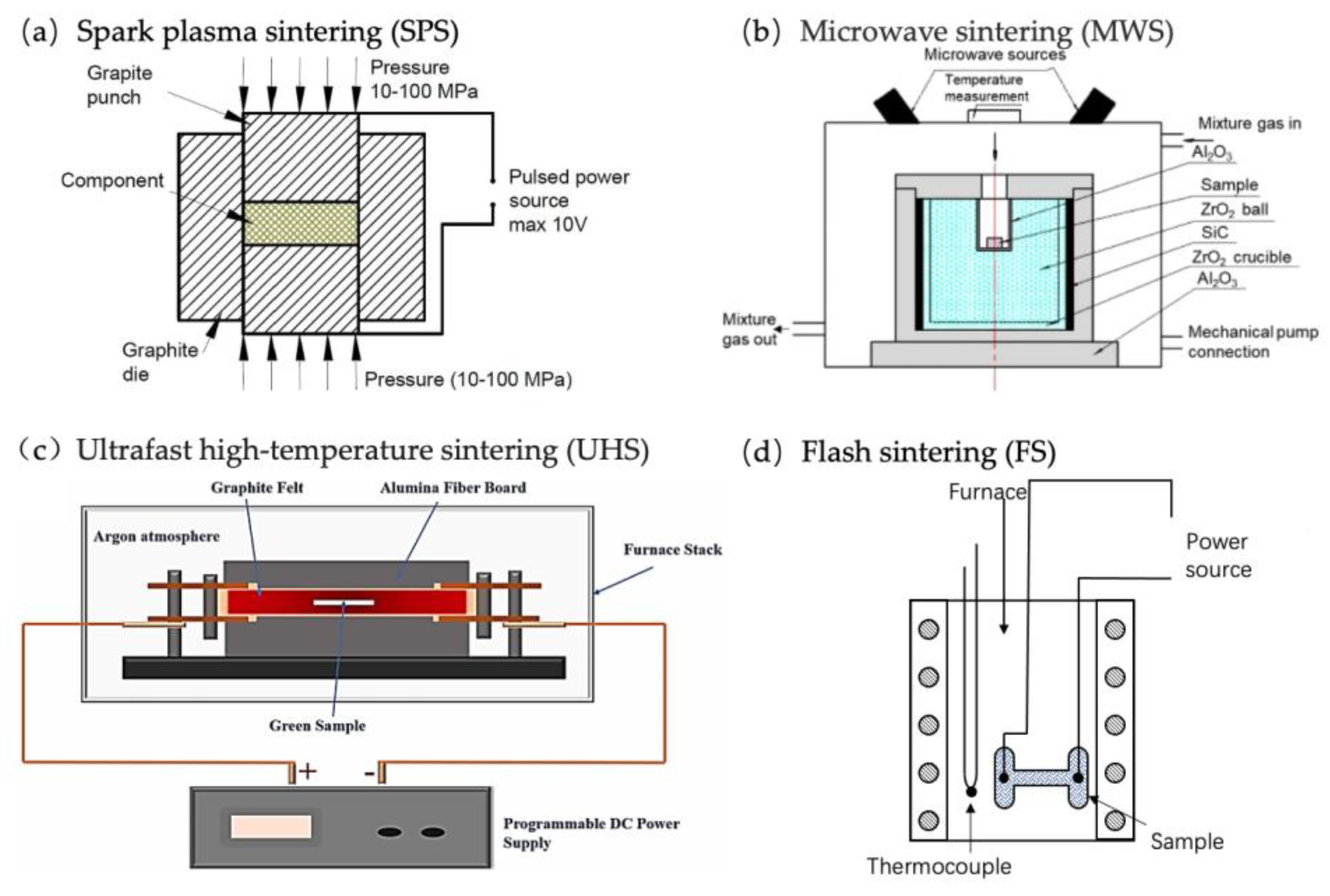
Figure 1. Schematic diagram of the operating principle for SOFCs.
Applsci 14 03953 g001
Figure 2. Sketches of different typical field-assisted and current-assisted sintering processes: (a) spark plasma sintering, (b) microwave sintering, (c) ultrafast high-temperature sintering, (d) flash sintering. ((a,d) reproduced from [39] with permission from Elsevier, (b) reproduced from [40], (c) reproduced from [41] with permission from Elsevier).
Applsci 14 03953 g002
Figure 3. Arrhenius plot of ionic conductivities of the current-limiting flash-sintered 8YSZ samples (a) under the electric field of 100 V/cm, (b) under the electric field of 300 V/cm. (Reproduced from [75] with permission from Elsevier).
Applsci 14 03953 g003
Figure 4. SEM of the samples sintered with or without (0 V/cm) the application of an electrical field. (a) 0 V/cm, (b) 20 V/cm, (c) 30 V/cm, (d) 40 V/cm, (e) 50 V/cm, and (f) 70 V/cm. (Reproduced from [77] with permission from Elsevier).
Applsci 14 03953 g004
Figure 5. Schematic of DC-sintering device. (Reproduced from [70] with permission from Elsevier).
Applsci 14 03953 g005
Figure 6. Time dependence of (a) different limited current density and applied electric field, (b) power dissipation of LSGM samples during SCFS process. (Reproduced from [86] with permission from Elsevier).
Applsci 14 03953 g006
Figure 7. Illustration of a DC-assisted sintering device. The current radiates from the central part of the electrolyte to the edge. (Reproduced from [105] with permission from Elsevier).
Applsci 14 03953 g007
Figure 8. Grain size with (a) DC-assisted sintering and (b) conventional sintering. (Reproduced from [105] with permission from Elsevier).
Applsci 14 03953 g008
Figure 9. Micrographs of the cross sections of conventionally sintered and flash-sintered specimens of multilayers. (Reproduced from [103] with permission from John Wiley and Sons).
Applsci 14 03953 g009
Figure 10. SEM images of an LST–Ni/YSZ FGA-supported SOFC obtained by FS. (a) Cross-section of the anode and YSZ electrolyte, (b) magnification of the labeled part of (a). (Reproduced from [108] with permission from Elsevier).
Applsci 14 03953 g010
Figure 11. SEM image of a cross-section of a planar unitary three-layer cell after FS with 310 V/cm, 1 kHz, 1 A, for 5 min at 1200 °C. (Reproduced from [109] with permission from John Wiley and Sons).
Applsci 14 03953 g011
Figure 12. The setup of FS with different samples: GDC, GDC-LSCF-17, GDC-LSCF-10, and GDC-LSCF-5. (Reproduced from [110] with permission from Elsevier).
Applsci 14 03953 g012
Figure 13. Pictures of various ceramics sintered by the UHS technique in ~10 s. (Reproduced from [43] with permission from the American Association for the Advancement of Science).
Applsci 14 03953 g013
Figure 14. The schematic of (a) UHS setup and (b) TI-UHS setup. (Reproduced from [127] with permission from Elsevier).
Applsci 14 03953 g014
Figure 15. Electrode and electrolyte multilayered materials obtained by UHS multistep process. (Reproduced from [102] with permission from Elsevier).
Applsci 14 03953 g015
Figure 16. SEM and EDS mapping of the cermet composed of Ni-based superalloy and YSZ (1:4 in volume) sintered by the ultrafast method. (a) SEM image of sintered cermet, (b) EDS mapping of the sintered cermet, (c) EDS mapping of Ni, (d) EDS mapping of Zr, (e) EDS mapping of Y, (f) EDS mapping of O. (Reproduced from [131] with permission from Elsevier).
Applsci 14 03953 g016
Table 1. Comparison of conventional sintering with other fast sintering techniques.
Sintering TechniqueMajor MechanismTypical Heating Rate (°C min−1)Typical Dwelling Time (min)Typical Process AdvantagesMajor LimitationsReferences
CSThe furnace transfers heat to the sample through radiation, conduction, and convection.1–10>120Simple equipment, with no restrictions on sample size and shape.Time-consuming and energy-consuming. Samples exhibit coarse grains. Restricted low melting point materials that can be co-processed with the ceramic.[39,49]
MWSThe materials absorb microwave energy to provide volumetric heating.100<10Uniform heating, low energy consumption, the ability to sinter complex-shaped samples. Samples exhibit uniform microstructure, high density, and excellent mechanical properties.The equipment is complex, and the process requires microwave absorption properties of the materials or uses susceptors. Utilizing the dielectric loss of the material to heat the sample.[36,37,50]
SPSThe electric current generates Joule heating within the sample.102–103<20Low sintering temperature, fast speed, and high efficiency. Samples exhibit high density and fine grain size.The equipment is complex and expensive, pressure-assisted, and has limitations in part dimension and geometries.[31,51]
FSThe electric current generates Joule heating within the sample. Promotion of the ion diffusion depending on the material system.103–104<1Fast sintering speed, fine-grained samples.The sample was simple in shape and limited in size. The process usually requires expensive Pt electrodes and preheating, and depends strongly on the electrical characteristics of the material. Heterogeneous microstructure.[52,53]
UHSThe electric current generates Joule heating within the carbon felt, which is then transferred to the sample through thermal radiation and conduction.103–104<1Simple equipment, rapid heating rate, and the ability to sinter complex shapes or layered materials.It cannot be used for sintering materials requiring oxidizing atmosphere, and the temperature control of carbon felt is inadequate.[43]
Table 2. Properties of YSZ samples obtained from different sintering techniques.
Sintering MethodMaterialSintering Temperature (°C)Dwelling TimeOther Sintering Parameters Average Grain Size (μm)Density (%)Conductivity at 850 °C (S/cm)References
CS8YSZ150012 h/1297.50.051[135]
SPS8YSZ1100480 sApplied pressure: 110 MPa0.21960.057[135]
MWS8YSZ1500/Power: 1.1 kW
Frequency: 2.45 GHz
0.9980.036[136]
FS8YSZ565 (furnace temperature)600 sElectric field: 300 V/cm
Current density: 67 mA/mm2
0.2960.056[75]
UHS3YSZ175560 sCurrent: 35 A
Carbon felt: 80 × 30 × 5 mm3
0.1899/[127]
8YSZ1439120 sCurrent: 13 A
Carbon felt: 40 × 9.5 × 4 mm3
1.998.6/[128]
Table 3. Properties of GDC samples obtained from different sintering techniques.
Sintering MethodMaterialSintering Temperature (°C)Dwelling TimeOther Sintering Parameters Average Grain Size (μm)Density (%)Conductivity at 600 °C (S/cm)References
CS10GDC150010 h/1.295~0.008[137]
SPS10GDC980300 sApplied pressure: 50 MPa~0.298~0.01[138]
MWS10GDC1500/Maximum power: 5 kW
Frequency: 2.5 GHz
0.995~0.05[139]
FS10GDC600 (furnace temperature)120 sElectric field: 100 V/cm
Current density: 13.5 mA/mm2
0.298.90.013[65]
UHS10GDC>1500360 sCurrent: stepwise to 25 A
Carbon felt: 30 × 20 × 6 mm3
/95/[102]
Disclaimer/Publisher’s Note: The statements, opinions and data contained in all publications are solely those of the individual author(s) and contributor(s) and not of MDPI and/or the editor(s). MDPI and/or the editor(s) disclaim responsibility for any injury to people or property resulting from any ideas, methods, instructions or products referred to in the content.

