
Friction and Wear Performances of Materials for Wind Turbine Sliding Bearing Bushes
1
School of Materials Science and Engineering, Shanghai University, Shanghai 200444, China
2
School of Mechanical Engineering, Xinjiang University, Urumqi 830047, China
*
Author to whom correspondence should be addressed.
Appl. Sci. 2024, 14(10), 3962; https://doi.org/10.3390/app14103962
Submission received: 1 April 2024
/
Revised: 27 April 2024
/
Accepted: 4 May 2024
/
Published: 7 May 2024
Abstract
:This study aimed to enhance the friction and wear characteristics of materials for wind turbine sliding-bearing bushes operating under low-speed and heavy-load conditions. To this end, a high-entropy CoCrFeNiMo alloy coating was applied to the surface of 9Cr18 bearing steel, and Ni-Cr-Mo-Si alloy coating was applied to MTCrMoCu30 wear-resistant cast iron using laser cladding. The effects of varying loads on the friction and wear properties of these coatings were investigated, and the friction and wear properties were compared. Furthermore, the overall priority indices for both groups of bearing bush coatings were assessed. The findings indicated that the friction coefficient, wear quality, and wear rate of CoCrFeNiMo high-entropy alloy coating initially decreased and then increased with the increase in applied load, dominated by abrasive wear. By contrast, the friction coefficient of the Ni-Cr-Mo-Si alloy coating increased, and wear quality and wear rate initially increased and then decreased, indicating the coexistence of adhesive wear and abrasive wear. Therefore, Ni-Cr-Mo-Si alloy coating exhibited a high overall priority index and favorable friction and wear properties.
1. Introduction
Wind power generation, a sustainable and renewable energy source, is gaining widespread recognition globally, prompting increased attention from governments worldwide [1,2,3,4]. Within wind turbines, rolling bearings serve as pivotal components in power transmission systems. However, the evolution of wind turbines towards higher power capacities has unveiled challenges associated with rolling bearings, including low power density, substantial radial dimensions, elevated costs, and a heightened failure rate. The integration of sliding bearings emerges as a viable solution to enhance transmission efficiency, diminish failure rates, and curtail economic expenditures, thereby promising a bright market outlook [5,6,7,8,9]. Nevertheless, the intricate operational conditions of wind power, characterized by low speeds and heavy loads, introduce complexities. Factors such as fluctuating wind loads, intricate structural coupling deformation, and heat generated by friction and wear pose formidable challenges to the utilization of plain bearings in the wind power sector [10,11,12].
A critical component of sliding bearings, the bearing bush, frequently experiences friction phenomena with the shaft diameter in low-speed, high-load working conditions. This interaction induces heightened friction and shear stress, ultimately resulting in bearing bush failure. The performance and longevity of sliding bearings are consequently compromised. Addressing this challenge necessitates a strategic approach, emphasizing the selection of appropriate materials for bearing coatings. This method aims to significantly enhance the bonding strength between the bearing bush matrix and coating, thereby effectively improving the anti-friction and wear resistance of the bearing bush [13,14,15,16]. AlcoverJunior et al. [17] demonstrated the superiority of tin-based babbitt alloy, prepared through arc spraying and flame spraying processes, over traditional methods. Similarly, Song Wenlong et al. [18] utilized spraying technology to apply a PTFE coating to Si3N4/TiC ceramics, resulting in a 65–80% reduction in friction coefficient compared with conventional samples.
Laser cladding, an advanced and environmentally friendly modification technology, employs a high-energy laser beam to melt substrates and powders. Compared with traditional coating preparation processes, laser cladding facilitates the thorough intermingling of alloy elements in the matrix and powder, refining grains, bolstering coating bonding strength, and enhancing the anti-friction and wear resistance of the bearing bush [19,20,21]. Despite the potential benefits, research on laser cladding technology for the preparation of anti-friction and wear-resistant coatings of bearing bush materials remains relatively scarce. This study addresses this gap by selecting two sets of matrix and powder materials, employing laser cladding technology to generate coatings on the substrate surface. The ensuing friction and wear tests, conducted under varying loads, comprehensively explore the tribological and wear properties of the coatings. This analysis encompasses macroscopic morphology, friction coefficient, wear quality, wear rate, and wear mark characteristics, providing valuable insights for the preparation of bearing shell coatings with superior friction and wear properties using laser cladding technology.
2. Materials and Experiments
2.1. Experimental Materials
2.2. Experimental Methods
2.2.1. Laser Cladding
The coatings were fabricated on two sets of matrix materials utilizing laser cladding technology. First, single coatings were prepared using different process parameters. Subsequently, optimal parameters were determined based on the macroscopic morphology and surface-forming quality of the single coating. Finally, the optimal technological parameters were employed to generate multiple coatings. The cladding equipment utilized a large IPG2000 fiber laser (IPG Photonics, Oxford, MA, USA) with high-purity argon gas as the protective gas. The working principle is depicted in Figure 1.
2.2.2. Friction and Wear Experiment
The multi-coated forming parts from the two groups were cut into specimens measuring 18 mm × 10 mm × 5 mm using an electric discharge cutting machine. The specimen coating was polished into a flat section using sandpaper with 180 meshes, 600 meshes, 800 meshes, and 1000 meshes, respectively, ensuring uniform surface roughness. The friction and wear experiment was conducted using the MFT5000 multifunctional friction (Rtec-instruments, San Jose, CA, USA) and wear testing machine at normal temperatures (20 °C), as shown in Figure 2. In the test, a high-purity silicon nitride ball with a diameter slightly exceeding the hardness of the substrate (9 mm) was selected as the grinding pair, with a frequency of 2 Hz, a wear time of 45 min, and a reciprocating stroke of 10 mm. The weight of the specimen was measured before and after the experiment using an FA224 electronic balance with an accuracy of 0.0001 g. The weight loss was calculated by comparing the quality of the samples before and after wear. Following the test, the three-dimensional contours of the scratches were observed with a VHX-6000 ultra-depth microscope (KEYENCE, Itasca, IL, USA). The wear length, depth, and volume were measured multiple times to obtain the average values, and the volume wear rate was calculated.
3. Wind Turbine Sliding Bearing Bearing Bush Coating Preparation
3.1. Numerical Calculation of Laser Cladding Power Parameters
The temperature field generated during laser cladding was numerically simulated using ANSYS software(Version 2022) based on the finite element method to determine the appropriate laser power parameters and enhance the forming quality of the cladding parts. The transient thermal changes of cladding parts during processing were analyzed [22,23,24]. In the numerical simulation, the laser energy density follows an approximately Gaussian distribution. Therefore, a Gaussian heat source model was chosen for simulation [25,26]. As illustrated in Figure 3, activities included establishing the finite element model, grid division, node setup and arranging the movement trajectory of the heat source. The dimensions of the substrate (length × width × thickness) were set at 50 mm × 50 mm × 10 mm, and the coating’s dimensions (length × radius of the semi-cylinder) were 50 mm × 2 mm. The mesh cell type selected was the highly flexible 8-node 6-hedron. Position grids near the coating were refined, resulting in a total of 4522 grids. This refinement ensured uniform heat transfer and calculation accuracy while reducing calculation time. Laser cladding was performed in the direction shown in Figure 3.
The laser Gaussian heat source, dynamic boundary conditions and material thermal and physical parameters were imposed to the 3D numerical model. Due to the large temperature span during the laser cladding process, if the thermal and physical properties of the material are considered to be independent of the temperature, it will affect the calculation results. Therefore, the relevant thermal and physical parameters used in this paper were calculated by JMatPro software(Version 7.0) according to the elemental composition of the material, as shown in Figure 4.Under scanning speed conditions of 6 mm/s, powder feeding capacity of 1.6 r/min, and defocusing capacity of 16 mm, a CoCrFeNiMo high-entropy alloy coating was prepared on the surface of 9Cr18 bearing steel with a power of 1300 W, while a Ni-Cr-Mo-Si alloy coating was prepared on the surface of MTCrMoCu30 wear-resistant cast iron with a power of 1000 W. As shown in Figure 3, five temperature acquisition points are set up on the cladding layer with a gradient of 5 mm to capture the change rule of nodal temperature with time. The temperature field cloud map at any point in the numerical simulation process and the temperature–time history change curves of different nodes are depicted in Figure 5. The elliptical temperature field is a result of the laser heat source focusing on a node, causing a sharp temperature increase, and as the laser heat source moves away, the temperature at the point decreases rapidly. Molten pools melt and solidify at different rates, necessitating a cooling period. The temperature change trend of different nodes with time is similar, reflecting the laser cladding processing characteristics of fast cooling and heating. However, the cooling rate is less than the heating rate, a phenomenon associated with the release of latent crystallization heat during the solidification process. The maximum temperature in the melting pool of the CoCrFeNiMo high-entropy alloy coating can reach 2221 °C, surpassing the melting point of 9Cr18 bearing steel (1371 °C) and CoCrFeNiMo high-entropy alloy(1350 °C). The highest temperature in the Ni-Cr-Mo-Si alloy coating pool can reach 2100 °C, exceeding the melting point of MTCrMoCu30 wear-resistant cast iron (1400 °C) and Ni-Cr-Mo-Si alloy (1420 °C). Both material groups successfully achieve the cladding effect, forming a robust metallurgical combination.
Based on the simulation results of the temperature field, adjustments were made to the power gradient to select the experimental parameters. Power parameters were chosen as 1100 W, 1300 W, and 1500 W based on the optimal power of 1300 W for the CoCrFeN0iMo high-entropy alloy coating. For the Ni-Cr-Mo-Si alloy coating, power parameters of 800 W, 1000 W, and 1200 W were selected based on the optimal power of 1000 W. Single-channel laser cladding experiments were analyzed separately. The macroscopic morphology was observed to select the optimal power parameters for multi-channel laser cladding. The experimental parameters for single-channel laser cladding are as follows: scanning speed 6 mm/s, powder feeding capacity 1.6 r/min, defocusing capacity 16 mm, and laser power, as shown in Table 3.
3.2. Experimental Verification of Laser Power Parameters
The macro morphologies of two groups of single coatings prepared under varying laser powers are depicted in Figure 6. As illustrated in Figure 6a–c, when the laser power is low, inadequate laser irradiation prevents powder melting, resulting in the deposition of large powder particles. Simultaneously, uneven heat in the molten pool leads to varied solidification rates, influencing the coating contour. Local overheating contributes to a yellowish tint on the coating. When the laser power increases to 1300 W, the coating surface becomes notably flat, displaying a metallic luster. Higher energy irradiation accelerates powder particle dissolution, mitigates the deposition effect, and enhances the forming quality of the coating surface. However, excessive laser power induces elevated melting pool temperatures, causing over-liquefaction of the powder and darkening of the coating color. Slow solidification rates and continuous flow in the molten pool result in oblique folds on the surface. Thus, at 1300 W, the optimal forming quality for the CoCrFeNiMo high-entropy alloy coating can be achieved through laser cladding.
As illustrated in Figure 6d–f, at 800 W laser power, insufficient irradiation energy causes incomplete melting of the cladding powder, leading to a phenomenon of sticky powder. The coating surface appears rough, high, narrow, and prone to peeling off, contributing to poor metallurgical fusion quality. At 1000 W laser power, the coating surface quality significantly improves, and the sticky powder phenomenon disappears. Higher energy density enhances molten pool wetting and fluidity, promoting uniform heat and mass transfer and increasing the dilution rate. The cladding trajectory exhibits regular and smooth contours. However, further increases in laser power result in excessive energy density, deepening and widening the molten pool. The cladding layer becomes flat, losing its effectiveness in surface modification. Simultaneously, the temperature gradient inside the molten pool rises, and the solidification rate increases, causing powder adhesion to the coating before complete melting. The sticky powder phenomenon reoccurs. In summary, for optimal forming quality in the preparation of Ni-Cr-Mo-Si alloy coating through laser cladding, the corresponding laser power is determined to be 1000 W.
The optimal process parameters were established through an interactive verification method involving simulation and single-pass cladding experiments. Based on a scanning speed of 6 mm/s, powder feeding capacity of 1.6 r/min, and defocusing capacity of 16 mm, CoCrFeNiMo high-entropy alloy coating was prepared on the surface of 9Cr18 bearing steel at 1300 W and 1000 W, respectively. Similarly, Ni-Cr-Mo-Si alloy coating was prepared on the surface of MTCrMoCu30 wear-resistant cast iron.
3.3. Wind Turbine Sliding Bearing Bearing Bush Material Single-Layer and Multi-Coating Preparation
The overlap rate of the multi-pass coatings for both material groups is set at 30%, and the macro morphology comparison is illustrated in Figure 7. The CoCrFeNiMo high-entropy alloy coating exhibits satisfactory performance near the two lap joints, although the surface appears dark yellow. The outline of each single coating is uneven and relatively rough. In contrast, the Ni-Cr-Mo-Si alloy coating surface is smooth and consistent, with compact lap joints between the two adjacent paths and a flat surface. Notably, the surface-forming quality of the Ni-Cr-Mo-Si alloy coating surpasses that of its counterpart.
4. Wind Turbine Sliding Bearing Bush Friction and Wear Properties Analysis
4.1. Load Calculation of Friction and Wear Test of Sliding Bearing Bush Material
Given the low-speed and heavy-load operating conditions of turbine sliding bearings, wear samples underwent equivalent variable loads to compare and analyze the friction and wear properties of each material group under different loads. The G-T contact model, often employed to predict parameters such as size, stress distribution, and friction force at the microscopic scale, serves as the theoretical basis for describing contact behavior. This model provides crucial theoretical support for studying material friction and wear properties [27,28]. In the process of calculating the bearing pressure of the wind turbine main shaft, the numerical model has a cross-section radius of 0.2 m and a shaft length of 0.3 m. The cylindrical main shaft tiles of equal dimensions are expanded into a rectangle whose length is the perimeter of the cross-section and width is the shaft length. The rectangle is meshed uniformly using the difference method. Then based on the G-T contact model, the pressure distribution of the main bearing of the wind turbine in the bearing area during normal operation can be obtained. The peak range of pressure is concentrated at 1.93 × 10⁹ Pa, as illustrated in Figure 8.
The Hertz contact stress calculation formula [29] can be expressed as follows:
where denotes the maximum contact compressive stress (MPa), F denotes the concentrated load (N), v represents Poisson’s ratio, E represents the elastic modulus of the material (MPa), R denotes the radius of the grinding ball (mm). The properties of the grinding pair materials are shown in Table 4.
By substituting the peak compressive stress in the bearing area of the main bearing of the fan under normal operation, the maximum load values for CoCrFeNiMo alloy coating and Ni-Cr-Mo-Si alloy coating were 33.07 N and 48.18 N, respectively. Based on this, loads of 30 N, 40 N, and 50 N were selected for the friction and wear experiments.
4.2. Analysis of Friction and Wear Properties of Two Groups of Bearing Bush Coatings under Different Loads
The characteristic change curve depicting the anti-friction and wear resistance of the surface of the multi-layer coating for both material groups under various loads is presented in Figure 9. The average friction coefficient represents the mean value and upper and lower deviations obtained by calculating the friction coefficient within the stable wear stage (within the range of 2.5–42.5 min). The friction coefficient curves for both groups of wear samples reveal a consistent pattern: an initial rise during the running-in stage, a subsequent sharp decline in the stable stage, followed by a sustained plateau, and finally, a gradual increase. In the running-in stage, under the influence of the normal load, micro-convex bodies between the grinding pairs come into close contact. This leads to shearing and extrusion on the material surface, causing an instantaneous increase in local stress and a rise in the friction coefficient. In the stabilization stage, the micro-convex bodies between the grinding pairs interleave and rub until fatigue yield is reached, resulting in their detachment from the material surface in the form of debris. Some debris accumulates on the edge of the wear mark with reciprocating motion, while another portion intensifies friction as the wear pair moves within the contour of the wear mark. The remaining debris is compacted to form a protective layer during the movement of the wear pair. When the effects of the latter two reach equilibrium, the friction coefficient enters a stable stage marked by zigzag fluctuations.
As illustrated in Figure 9a, the CoCrFeNiMo high-entropy alloy coating attains a minimum average friction coefficient of 0.45 under a 50 N load. As the applied load increases, the friction coefficient of the CoCrFeNiMo high-entropy alloy coating experiences an initial decrease followed by an increase. This phenomenon is attributed to the escalation of frictional shear stress under dry friction conditions with an increase in the applied load. Throughout the wear process, the generation of debris intensifies, some of which falls and embeds itself between the wear pairs. These debris are compacted under high loads, forming a relatively smooth protective layer. Simultaneously, the friction on the contact surface transitions from different materials to the same materials, further reducing the friction coefficient. However, as the load continues to increase, elastic deformation occurs on the specimen surface, leading to an increase in the contact area between the friction pairs. Consequently, the number of micro-convex peaks in actual contact increases, causing an increase in the friction coefficient. Additionally, under a 40 N load, the wear time for the sample to reach the stable stage is prolonged. This can be attributed to the enhanced anti-friction wear resistance of the coating surface, necessitating an extended run-in time. Figure 9c indicates that the Ni-Cr-Mo-Si alloy coating achieves a minimum average friction coefficient of 0.49 under a 30 N load. The friction coefficient increases with the rise in the applied load, with the overall minimum occurring under a 30 N load, signifying optimal anti-friction properties. With the increasing applied load, the shear motion between the grinding pairs intensifies, and the extrusion deformation of the coating surface becomes more pronounced, leading to an increase in the friction coefficient. Additionally, higher loads result in elevated micro-temperature rise between grinding pairs, fostering the formation of an oxide film on the surface of the wear marks, thereby intensifying friction and subsequently increasing the coefficient of friction.
The wear mass, wear rate, and relative wear resistance of the two groups were measured to characterize the coating surface’s wear performance and determine the impact of different loads on the wear resistance of the coating surface. Wear rate (ω) and relative wear resistance (ε) can be calculated using Formula (2) and (3), respectively [33,34]:
where m represents the wear mass, F represents the applied load, s represents the wear travel, represents the average wear mass, and represents the wear mass of a single sample (i = 1, 2, 3).
As depicted in Figure 9b,d, the wear quality and wear rate of the CoCrFeNiMo high-entropy alloy coating exhibit an initial decrease followed by an increase with an increase in applied load. Conversely, the change in relative wear resistance follows the opposite pattern, achieving optimal wear resistance under a 40 N load with a minimum wear mass of 2 mg. With increasing applied load, the wear quality and wear of the Ni-Cr-Mo-Si alloy coating initially increase and then decrease. The relative wear resistance experiences a decrease followed by an increase, reaching its minimum wear mass of 0.7 mg under a 50 N load, indicating optimal wear resistance. It is also worth noting that the average coefficient of friction and wear mass of CoCrFeNiMo high-entropy alloy coating are maximum at an applied load of 30 N, and the average coefficient of friction and wear mass of Ni-Cr-Mo-Si alloy coating are maximum at an applied load of 40 N. This is due to the fact that a higher average coefficient of friction leads to a greater interaction force between the pairs of grinding pairs, which increases the likelihood of wear and consequently causes an increase in wear mass.
4.3. Comparative Analysis of Friction and Wear Properties of Two Groups of Bearing Bush Materials
The experimental data on the friction and wear of the two groups of coated surfaces under the same load were compared and analyzed to identify a bearing material with superior friction and wear properties, as illustrated in Figure 10 and Table 5. The standard deviation of the friction coefficient reflects the degree of fluctuation in the friction coefficient of the coating during the stable wear stage [35]. A smaller standard deviation value indicates a more stable friction coefficient, as given by Formula (4):
where is the size of the friction coefficient of each sample, is the average friction coefficient, and n is the amount of data in the sample.
As depicted in Figure 10a–c, under a 30 N load, the variation trend of the friction coefficients for the two groups is nearly identical, and the difference in average friction coefficients is less than 1%. Thus, the frictional properties of the two groups of coating surfaces are comparable under a 30 N load. Under 40 N and 50 N loads, the friction coefficient of the CoCrFeNiMo high-entropy alloy coating is lower than that of the Ni-Cr-Mo-Si alloy coating. The average friction coefficient is lower by 0.0579 and 0.0599, respectively, indicating a small difference. Additionally, the data in Table 5 indicate that the standard deviation of the friction coefficient for the CoCrFeNiMo high-entropy alloy coating is large under 40 N and 50 N loads, and the friction curve during the stable wear stage is highly volatile, resulting in an unstable friction coefficient. Therefore, relying solely on the friction coefficient is inadequate for material selection.
As illustrated in Figure 10d, the wear characteristics and wear rates of the CoCrFeNiMo high-entropy alloy coating surpass those of the Ni-Cr-Mo-Si alloy coating under identical load conditions. Specifically, the wear mass of the CoCrFeNiMo high-entropy alloy coating is at its minimum under a 40 N load, measuring 2 mg. In contrast, the lowest wear mass for the Ni-Cr-Mo-Si alloy coating is 0.7 mg, achieved under a 50 N load. Table 5 further highlights that, under equivalent load conditions, the wear rate of the CoCrFeNiMo high-entropy alloy coating significantly exceeds that of the Ni-Cr-Mo-Si alloy coating, reaching up to six times. This phenomenon can be attributed to laser cladding, which ensures even distribution of powder alloy elements with high wear resistance in the coating. These elements fully fuse with the hard strengthening phase embedded in the wear-resistant cast iron, resulting in a substantial enhancement of the coating’s wear performance. It is worth noting that the change in the coefficient of friction of the CoCrFeNiMo high-entropy alloy coating and the Ni-Cr-Mo-Si alloy coating is almost the same under an applied load of 30 N, but the wear quality is different. This is because the surface of the Ni-Cr-Mo-Si alloy coating is flatter compared to the CoCrFeNiMo high-entropy alloy coating, as shown in Figure 7. In the very short time at the beginning of the friction and wear experiment, the friction between the relatively rough CoCrFeNiMo high-entropy alloy coating and the counter-abrasive ball occurs more violently, with more broken micro-convex bodies and dropped abrasive chips on the coating surface. After this, the wear depth of both groups of materials gradually reaches below the coating surface, with similar friction coefficients and comparable wear quality. Therefore, in the whole frictional wear process, the wear quantity on the surface of CoCrFeNiMo high-entropy alloy coating is larger.
The friction and wear properties of the coatings from both material groups were compared and optimized based on the results of the PSI (Preference Selection Index) method [36,37]. Commonly used in material selection, the PSI method integrates performance indexes such as wear rate, average friction coefficient, and standard deviation of the friction coefficient for both groups of coatings. All performance parameters were standardized, and the overall priority index was subsequently calculated. The results indicate that the overall priority index for the CoCrFeNiMo high-entropy alloy coating is 0.71419, whereas the overall priority index for the Ni-Cr-Mo-Si alloy coating is 0.9736. In conclusion, the overall priority index of the CoCrFeNiMo high-entropy alloy coating surpasses that of the Ni-Cr-Mo-Si alloy coating. However, it is essential to note that the friction and wear properties of the Ni-Cr-Mo-Si alloy coating are superior.
Figure 10.
Friction coefficient and wear quality of different materials: (a) 30 N, (b) 40 N, (c) 50 N, (d) average coefficient of friction and wear amount of comparison.
Figure 10.
Friction coefficient and wear quality of different materials: (a) 30 N, (b) 40 N, (c) 50 N, (d) average coefficient of friction and wear amount of comparison.


Table 5.
Comparison of friction and wear data of the two groups of material coatings.
| Bearing Bush Material | Properties Parameter | 30 N | 40 N | 50 N |
|---|---|---|---|---|
| CoCrFeNiMo High-entropy alloy coating | Mean friction coefficient | 0.4987 | 0.4664 | 0.4545 |
| Standard Deviation of friction coefficient | 0.03591 | 0.0272 | 0.0202 | |
| Wear rate | 1.81% | 0.52% | 0.62% | |
| Ni-Cr-Mo-Si Alloy coating | Mean friction coefficient | 0.4986 | 0.5243 | 0.5144 |
| Standard Deviation of friction coefficient | 0.0361 | 0.0150 | 0.0098 | |
| Wear rate | 0.30% | 0.33% | 0.14% |
4.4. Surface Wear Morphology Analysis of Two Groups of Bearing Bush Materials
The evaluation of material friction and wear properties encompasses critical indices, with the friction and wear of coating surfaces playing a pivotal role [14,38]. The three-dimensional wear morphology of these surfaces under varying loads was scrutinized using an ultra-depth microscope, as detailed in Figure 11. Scratches on the CoCrFeNiMo high-entropy alloy coating exhibited regular patterns, featuring a relatively smooth edge transition. Notably, the depth of the wear mark first increased and then decreased with the increase in applied load. By contrast, both the length of the wear mark and the wear surface area exhibited an initial decrease followed by an increase. Conversely, the scratches on the Ni-Cr-Mo-Si alloy coating exhibited relatively irregular profiles. Nevertheless, the overall wear marks were characterized by small and smooth patterns. When the applied load increased, the wear length exhibited an initial decrease followed by an increase, while both wear depth and surface area exhibited an increasing trend. The wear mechanisms are elucidated in Figure 12. Abrasive wear was the dominant mechanism in the CoCrFeNiMo high-entropy alloy coating. With the increase in the applied load, the coating experienced peeling, with partially detached wear chips adhering to the grinding pair. This resulted in more violent plastic deformation on the surface of the wear marks, generating furrows. By contrast, the wear mechanism of the Ni-Cr-Mo-Si alloy coating primarily involved both adhesive and abrasive wear. With an increase in the applied load, more abrasion marks and furrows appeared on the worn surface, intensifying the surface peeling phenomenon to varying degrees on both sides.
5. Conclusions
In addressing the investigation of fan plain bearing materials operating under low-speed and heavy-load conditions, this study employed laser cladding technology to apply CoCrFeNiMo high-entropy alloy coating on the surface of 9Cr18 bearing steel and Ni-Cr-Mo-Si alloy coating on the surface of MTCrMoCu30 wear-resistant cast iron. Macroscopic morphology as well as friction and wear properties were meticulously observed and analyzed, yielding the following conclusions:
- Optimal laser power settings were determined through numerical simulation and single-pass cladding experiments. For CoCrFeNiMo high-entropy alloy coating on 9Cr18 bearing steel, the ideal power was determined to be 1300 W. While the coating exhibited strong interlayer bonding, the surface appeared dark yellow and rough. In the case of Ni-Cr-Mo-Si alloy coating on MTCrMoCu30 wear-resistant cast iron, the optimal power was found to be 1000 W, resulting in a tightly bonded coating with a flat surface.
- The CoCrFeNiMo high-entropy alloy coating demonstrated a minimum mean friction coefficient of 0.45 at a 50 N load, with a minimum wear mass of 2 mg achieved at a 40 N load. Conversely, the Ni-Cr-Mo-Si alloy coating exhibited a minimum mean friction coefficient of 0.49 at a 30 N load, with a minimum wear mass of 0.7 mg achieved at a 50 N load. With an increase in applied load, the friction coefficient, wear quality, and wear rate of CoCrFeNiMo high-entropy alloy coating initially decreased and then increased. Conversely, the friction coefficient of Ni-Cr-Mo-Si alloy coating increased with the applied load, with wear quality and wear rate initially increasing and then decreasing.
- The friction curve of CoCrFeNiMo high-entropy alloy coating displayed considerable fluctuation, resulting in relatively large wear volume and wear rate. In contrast, the friction coefficient of Ni-Cr-Mo-Si alloy coating remained relatively stable, with low wear quality and wear rate. Comparatively, the overall priority index of Ni-Cr-Mo-Si alloy coating was higher. Therefore, Ni-Cr-Mo-Si alloy coating, prepared on the surface of MTCrMoCu30 wear-resistant cast iron using laser cladding technology, effectively enhances the friction and wear properties of sliding bearing bush.
- In the experimental load range, the wear depth of CoCrFeNiMo high-entropy alloy coating initially increased and then decreased with the applied load, while wear scar length and wear surface area initially decreased and then increased. The predominant wear mechanism observed was abrasive wear. Conversely, the wear length of Ni-Cr-Mo-Si alloy coating initially decreased and then increased, with wear depth and wear surface area increasing. The wear mechanism for this coating involved the coexistence of adhesive wear and abrasive wear.
Author Contributions
Methodology, J.M.; Software, J.C.; Validation, J.C.; Investigation, L.L. and X.L.; Resources, J.M.; Data curation, J.C.; Writing—original draft, J.C.; Writing—review & editing, J.M., L.L. and X.L.; Supervision, L.L. and X.L.; Funding acquisition, J.M. All authors have read and agreed to the published version of the manuscript.
Funding
This research is supported by the Key R&D Program of Xinjiang Province (Grant No. 2022B01017).
Institutional Review Board Statement
Not applicable.
Informed Consent Statement
Not applicable.
Data Availability Statement
The original contributions presented in the study are included in the article, further inquiries can be directed to the corresponding author.
Conflicts of Interest
The authors declare that they have no known competing financial interests or personal relationships that could have appeared to influence the work reported in this paper.
References
- Liu, B.; He, Z.; Hao, J. Current situation And Development Trend of Wind Power Generation. J. Northeast Electr. Power Univ. 2016, 36, 7–13. [Google Scholar]
- Zhang, J. Analysis and optimization of power generation performance of wind turbines. China Equip. Eng. 2021, 17, 117–118. [Google Scholar]
- Zhang, M. Discussion on wind power generation and its technological development. China Equip. Eng. 2022, 4, 200–201. [Google Scholar]
- Wang, Y.; Zou, R.; Liu, F.; Zhang, L.; Liu, Q. A review of wind speed and wind power forecasting with deep neural networks. Appl. Energy 2021, 304, 117766. [Google Scholar] [CrossRef]
- Dhanola, A.; Garg, H.C. Tribological challenges and advancements in wind turbine bearings, A review. Eng. Fail. Anal. 2020, 118, 104885. [Google Scholar] [CrossRef]
- Jin, X.; Chen, Y.; Wang, L.; Han, H.; Chen, P. Failure prediction, monitoring and diagnosis methods for slewing bearings of large-scale wind turbine, A review. Measurement 2021, 172, 108855. [Google Scholar] [CrossRef]
- Bobzin, K.; Wietheger, W.; Jacobs, G.; Bosse, D.; Schröder, T.; Rolink, A. Thermally sprayed coatings for highly stressed sliding bearings. Wear 2020, 458, 203415. [Google Scholar] [CrossRef]
- Chen, Q.; Zhang, K.; Zhu, J. Development status of wind power sliding bearing design and performance testing technology. Bearing 2023, 6, 14–19. [Google Scholar]
- de Azevedo, H.D.M.; Araújo, A.M.; Bouchonneau, N. A review of wind turbine bearing condition monitoring, State of the art and challenges. Renew. Sustain. Energy Rev. 2016, 56, 368–379. [Google Scholar] [CrossRef]
- Ji, K.F. Application of plain bearing in Wind power Gearbox. Shanxi Metall. 2017, 40, 116–117. [Google Scholar]
- Zhou, H.; Zhou, J.; Wen, J. Research Progress of Wind Power Bearing Failure Mode. Bearing 2023, 06, 102–114. [Google Scholar]
- Wang, H. Analysis of Reasons for Low Speed Tile Burning of Turbine Plain Bearing. Bearing 2019, 10, 39–42. [Google Scholar]
- Bill, S.; Bill, V. Lifetime extension of gears and main bearings in wind turbines, scientific calculations and practical implementation. IOP Conf. Ser. Earth Environ. Sci. 2022, 1073, 012001. [Google Scholar] [CrossRef]
- Shi, G.; Yu, X.; Meng, H.; Zhao, F.; Wang, J.; Jiao, J.; Jiang, H. Effect of surface modification on friction characteristics of sliding bearings, A review. Tribol. Int. 2023, 177, 107937. [Google Scholar] [CrossRef]
- Sun, Z.; Zhang, Y.; Yuan, R.; Zhan, S.; Zhang, D.; Wang, S.; Zhang, M. Preparation and application of a carbon fiber composite bearing material. J. Petrochem. Technol. 2023, 36, 63. [Google Scholar]
- Gong, X. Preparation and Properties of Bearing Bush Wear-Resistant Coating; Southeast University: Dhaka, Bangladesh, 2020. [Google Scholar]
- Junior, P.R.C.A.; Pukasiewicz, A.G.M. Evaluation of microstructure, mechanical and tribological properties of a Babbitt alloy deposited by arc and flame spray processes. Tribol. Int. 2018, 131, 148–157. [Google Scholar] [CrossRef]
- Song, W.; Wang, S.; Lu, Y.; Zhang, X.; Xia, Z. Friction behavior of PTFE-coated Si3N4/TiC ceramics fabricated by spray technique under dry friction. Ceram. Int. 2020, 47, 7487–7496. [Google Scholar] [CrossRef]
- Yang, J.; Ma, W.; Zhang, W.; Wang, X.; Huang, K.; Liu, Z.; Zhou, Z.; Xu, H.; Xiao, J. The dynamic load-bearing performance of the laser cladding Fe-based alloy on the U75V rail. Int. J. Fatigue 2022, 165, 107180. [Google Scholar] [CrossRef]
- Chen, J.; Huang, W.; Li, F.; Miu, D.; Zhou, J. Application of Arc Additive Manufacturing Technology in the Field of plain Bearing. Bearing 2021, 7, 1–7. [Google Scholar]
- Hao, Y.; Zhao, K.; Yang, P.; Zhu, Z.; Yang, Y. Microscopic Organization And Mechanical Properties of Laser Cladding Sn-based Ba Alloy. Chin. J. Nonferrous Met. 2018, 10, 2016–2023. [Google Scholar]
- Liu, L.; Zhang, J.; Liu, D.; Cui, J.; Jia, Z. ANSYS Numerical Simulation of Laser-Coated Ni/SiC Process Parameter Optimization. J. Harbin Univ. Sci. Technol. 2022, 27, 81–91. [Google Scholar]
- Yao, F.; Fang, L. Thermal stress cycle simulation in laser cladding process of Ni-based coating on H13 steel. Coatings 2021, 11, 203. [Google Scholar] [CrossRef]
- Wang, C.; Zhou, J.; Zhang, T.; Meng, X.; Li, P.; Huang, S. Numerical simulation and solidification characteristics for laser cladding of Inconel 718. Opt. Laser Technol. 2022, 149, 107843. [Google Scholar] [CrossRef]
- He, G.; Wang, T. Finite Element 3 D Numerical Model for Laser Polishing Based on A Mobile Gaussian Heat Source. Laser IR 2021, 51, 575–583. [Google Scholar]
- Gao, J.; Wu, C.; Hao, Y.; Xu, X.; Guo, L. Numerical simulation and experimental investigation on three-dimensional modelling of single-track geometry and temperature evolution by laser cladding. Opt. Laser Technol. 2020, 129, 106287. [Google Scholar] [CrossRef]
- Zhang, Y. Simulation of Lubrication-Wear Dynamic Coupling of Multi-Cylinder Internal Combustion Engine for Low Viscosity Oil; Zhejiang University: Hangzhou, China, 2021. [Google Scholar]
- Tang, Y.; Lin, Y.; Huang, L.; Li, L.; Meng, X. Analysis of Elastic-Plastic Contact on The Surface of Honing Cylinder Sleeve and Piston Ring. J. Tribol. 2022, 43, 1026–1033. [Google Scholar]
- Gao, S.; Han, Q.; Chu, F. Dynamic Characteristics and slip-state analysis of angular contact rolling bearing considering heat-fluid-structure Coupling. Chin. J. Mech. Eng. 2019, 58, 87–97. [Google Scholar]
- Wang, W.; Zhang, J.; Yan, J. Effect of Sintering Auxiliary Agent Content on Densification And Mechanical Properties of Silicon Nitride Ceramic Balls. Bearing 2021, 4, 23–27. [Google Scholar]
- Hongyang, X.U.; Jinbin, L.U.; Xuan, P.E.N.G.; Mingxing, M.A.; Wenglu, M.E.N.G.; Hongzhe, L.I. Microstructure and phase stability analysis of Laser cladding CoCrCu0.4FeNi high entropy alloy coating. Powder Metall. Technol. 2023, 41, 1–11. [Google Scholar]
- Chu, Y.; Chen, Y.; Chen, Y.; Liu, P.; Li, X. Microstructure and Corrosion Behavior of Ni-Cr-Mo Nickel-based Alloy Weld. Mater. Res. 2020, 23, e20190631. [Google Scholar] [CrossRef]
- Yu, J.; Sun, W.; Zhang, G.; Cui, Q.; Jiao, H. Effect of Variable Specific Energy Laser Remelting on the Morphology, Microstructure, and Mechanical Properties of Ta/Ni-Based Composite Coatings. JOM 2023, 75, 4158–4170. [Google Scholar] [CrossRef]
- Cui, Q. Study on Microstructure Evolution and Property Control of Laser Cladding IN718 Nickel-Based Superalloy; Xinjiang University: Ürümqi, China, 2021. [Google Scholar]
- Sun, Y.; He, K.; Zhang, Z. Regression integration model for fitting friction coefficient with multi-source information. J. Tsinghua Univ. 2022, 62, 1980–1988. [Google Scholar]
- Maniya, K.; Bhatt, M.G. A selection of material using a novel type decision-making method, Preference selection index method. Mater. Des. 2010, 31, 1785–1789. [Google Scholar] [CrossRef]
- Ji, Z.; Jin, H.; Luo, W.; Zhou, K.; Hou, S. Tribological properties and optimization of granulated zirconia reinforced composites. J. Tsinghua Univ. (Sci. Technol.) 2019, 60, 638–647. [Google Scholar]
- Bao, J.; Cao, B.; Li, F.; Fang, Y.; Liu, Z. Experimental study on friction and wear characteristics of cylinder-piston ring of oil-free compressor. J. Fluid Mach. 2023, 51, 1–5. [Google Scholar]
Figure 1.
Schematic diagram of the principle of laser cladding.

Figure 2.
MFT5000 Multi-function friction and wear testing machine.

Figure 3.
The 3D numerical model.
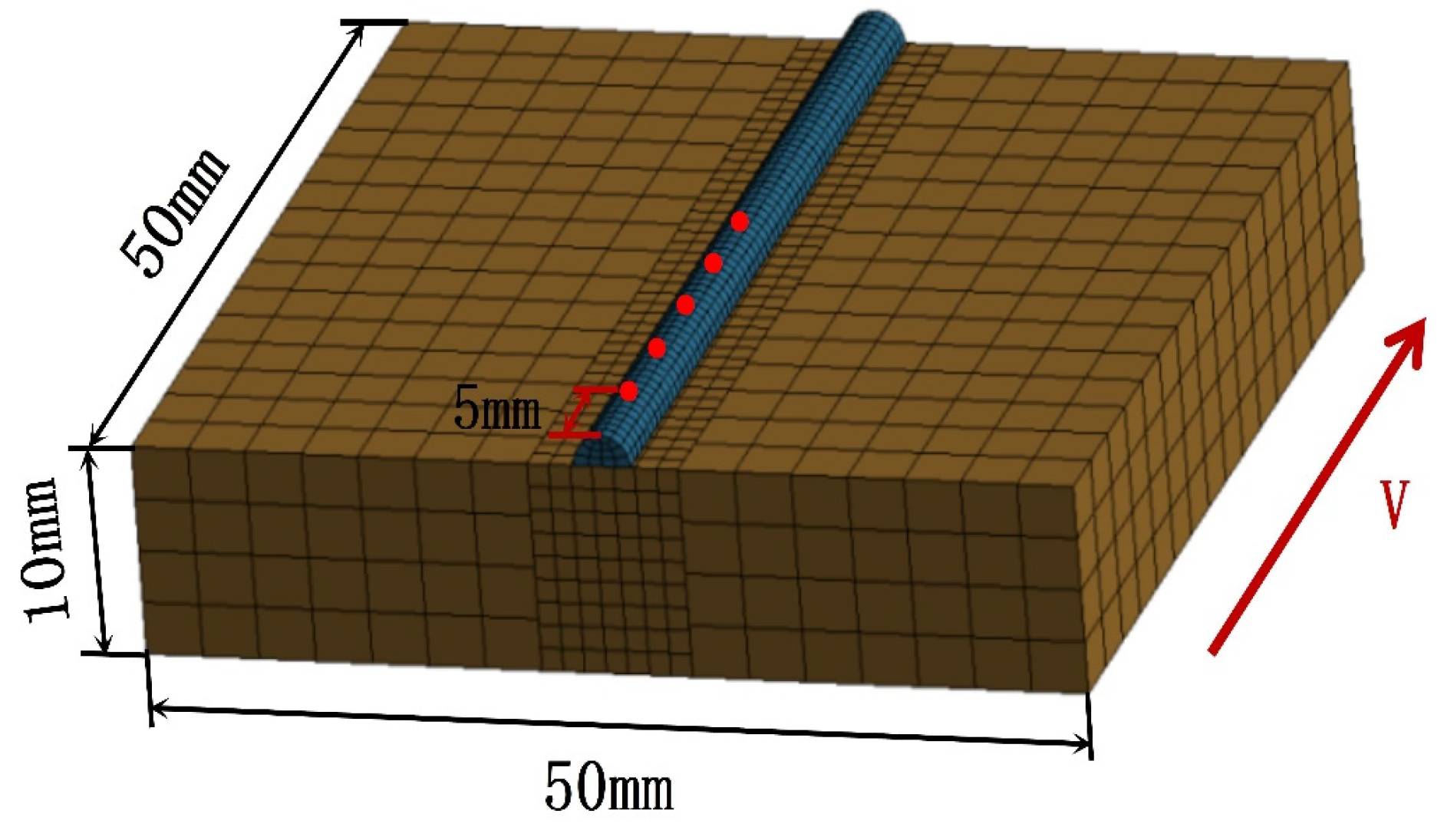
Figure 4.
Thermal property parameters of each material. (a) 9Cr18 bearing steel; (b) CoCrFeNiMo high entropy alloy; (c) MTCrMoCu30 wear-resistant cast iron; (d) Ni-Cr-Mo-Si alloy.
Figure 4.
Thermal property parameters of each material. (a) 9Cr18 bearing steel; (b) CoCrFeNiMo high entropy alloy; (c) MTCrMoCu30 wear-resistant cast iron; (d) Ni-Cr-Mo-Si alloy.

Figure 5.
Laser cladding temperature field cloud map and temperature–time course curve. (a,b) Temperature field nephogram; (c,d) Temperature–time course curve; (a,c) 9Cr18 bearing steel surface cladding CoCrFeNiMo High-entropy alloy; (b,d) MTCrMoCu30 wear-resistant cast iron surface cladding Ni-Cr-Mo-Si alloy.

Figure 6.
Macroscopic morphologies of the single-channel coating corresponding to different process parameters: (a–c) CoCrFeNiMo high-entropy alloy coating: (a) 1100 W, (b) 1300 W, (c) 1500 W; (d–f) Ni-Cr-Mo-Si alloy coating: (d) 800 W, (e) 1000 W, (f) 1200 W.
Figure 6.
Macroscopic morphologies of the single-channel coating corresponding to different process parameters: (a–c) CoCrFeNiMo high-entropy alloy coating: (a) 1100 W, (b) 1300 W, (c) 1500 W; (d–f) Ni-Cr-Mo-Si alloy coating: (d) 800 W, (e) 1000 W, (f) 1200 W.
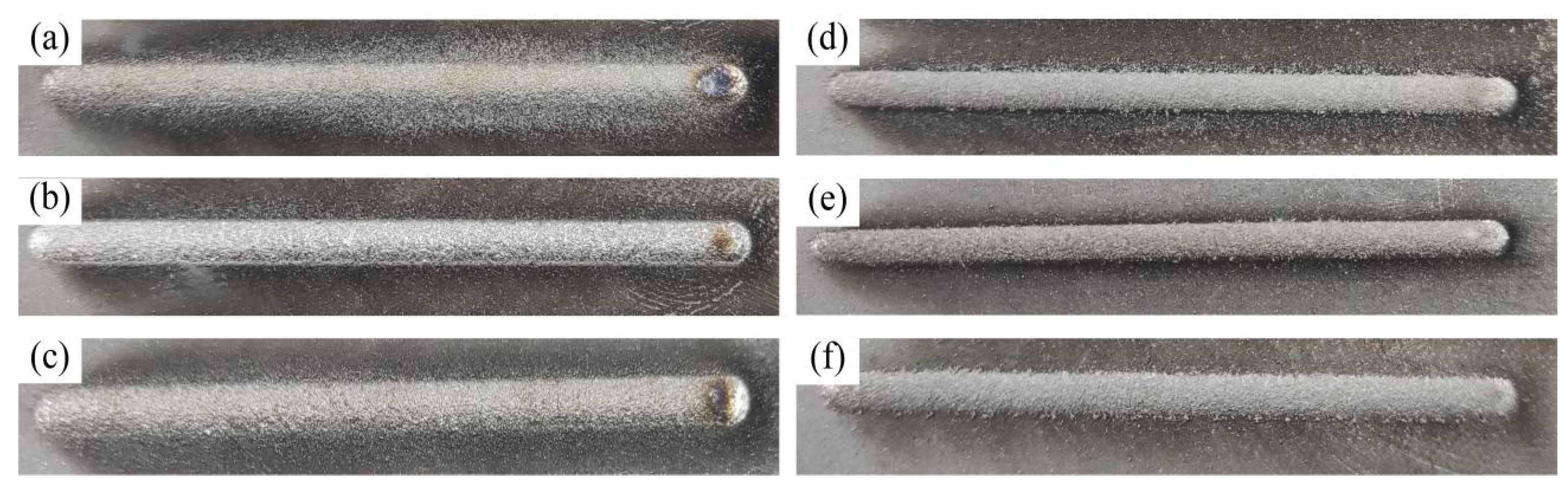
Figure 7.
Comparison of the macroscopic morphology of multiple coatings of different materials: (a) CoCrFeNiMo high-entropy alloy coating, (b) Ni-Cr-Mo-Si alloy coating.
Figure 7.
Comparison of the macroscopic morphology of multiple coatings of different materials: (a) CoCrFeNiMo high-entropy alloy coating, (b) Ni-Cr-Mo-Si alloy coating.

Figure 8.
Pressure bearing area of the fan main bearing.

Figure 9.
Friction and wear analysis of coatings under different loads: (a,b) CoCrFeNiMo high-entropy alloy coatings, (c,d) Ni-Cr-Mo-Si alloy coatings.
Figure 9.
Friction and wear analysis of coatings under different loads: (a,b) CoCrFeNiMo high-entropy alloy coatings, (c,d) Ni-Cr-Mo-Si alloy coatings.

Figure 11.
Surface wear and morphology of the two groups of materials: (a–c) CoCrFeNiMo high-entropy alloy coating; (d–f) Ni-Cr-Mo-Si alloy coating; (a,d) 30 N; (b,c) 40 N; (c,f) 50 N.
Figure 11.
Surface wear and morphology of the two groups of materials: (a–c) CoCrFeNiMo high-entropy alloy coating; (d–f) Ni-Cr-Mo-Si alloy coating; (a,d) 30 N; (b,c) 40 N; (c,f) 50 N.

Figure 12.
Microstructure of wear marks on the surface of the two groups of materials: (a–c) CoCr-FeNiMo high-entropy alloy coating; (d–f) Ni-Cr-Mo-Si alloy coating: (a,d) 30 N; (b,c) 40 N; (c,f) 50 N.
Figure 12.
Microstructure of wear marks on the surface of the two groups of materials: (a–c) CoCr-FeNiMo high-entropy alloy coating; (d–f) Ni-Cr-Mo-Si alloy coating: (a,d) 30 N; (b,c) 40 N; (c,f) 50 N.

Table 1.
Chemical composition of 9Cr18 bearing steel and CoCrFeNiMo high entropy alloy (wt.%).
| 9Cr18 bearing steel (substrate) | Fe | C | Si | Mn | P | S | Cr | Ni |
| 81.553 | 1.00 | 0.52 | 0.43 | 0.025 | 0.002 | 16.28 | 0.19 | |
| CoCrFeNiMo high entropy alloy (powder) | Fe | Co | Cr | Ni | Mo | / | / | / |
| 17.38 | 18.46 | 16.48 | 18.81 | 28.59 | / | / | / |
Table 2.
Chemical Composition of MTCrMoCu30 wear-resistant cast iron and Ni-Cr-Mo-Si alloy (wt.%).
| MTCrMoCu30 wear-resistant cast iron (substrate) | Fe | C | Si | Mn | P | S | Cr | Mo | Cu |
| 92.25 | 3.00 | 2.10 | 0.90 | 0.15 | 0.12 | 0.21 | 0.31 | 0.96 | |
| Ni-Cr-Mo-Si alloy (powder) | Ni | Cr | Mo | Si | / | / | / | / | / |
| 75.50 | 15.50 | 5.00 | 4.00 | / | / | / | / | / |
Table 3.
Different laser power schemes.
| Parameter Material | CoCrFeNiMo High Entropy Alloy Coating | Ni-Cr-Mo-Si Alloy Coating |
|---|---|---|
| Laser power/W | 1100 | 800 |
| 1300 | 1000 | |
| 1500 | 1200 |
Disclaimer/Publisher’s Note: The statements, opinions and data contained in all publications are solely those of the individual author(s) and contributor(s) and not of MDPI and/or the editor(s). MDPI and/or the editor(s) disclaim responsibility for any injury to people or property resulting from any ideas, methods, instructions or products referred to in the content. |
© 2024 by the authors. Licensee MDPI, Basel, Switzerland. This article is an open access article distributed under the terms and conditions of the Creative Commons Attribution (CC BY) license (https://creativecommons.org/licenses/by/4.0/).
Share and Cite
MDPI and ACS Style
Chen, J.; Min, J.; Li, L.; Liang, X. Friction and Wear Performances of Materials for Wind Turbine Sliding Bearing Bushes. Appl. Sci. 2024, 14, 3962. https://doi.org/10.3390/app14103962
AMA Style
Chen J, Min J, Li L, Liang X. Friction and Wear Performances of Materials for Wind Turbine Sliding Bearing Bushes. Applied Sciences. 2024; 14(10):3962. https://doi.org/10.3390/app14103962
Chicago/Turabian StyleChen, Jun, Jiahua Min, Linjie Li, and Xiaoyan Liang. 2024. "Friction and Wear Performances of Materials for Wind Turbine Sliding Bearing Bushes" Applied Sciences 14, no. 10: 3962. https://doi.org/10.3390/app14103962
Note that from the first issue of 2016, this journal uses article numbers instead of page numbers. See further details here.