
Porous and Ag-, Cu-, Zn-Doped Al2O3 Fabricated via Barrier Anodizing of Pure Al and Alloys


1
Research and Development Laboratory 4.10 “Nanotechnologies”, Belarusian State University of Informatics and Radioelectronics, 6 Brovki Str., 220013 Minsk, Belarus
2
Department of Electronic Technology and Engineering, Belarusian State University of Informatics and Radioelectronics, 6 Brovki Str., 220013 Minsk, Belarus
3
Department of Metallurgy, Federal University of Rio Grande do Sul, Porto Alegre 90040-060, Brazil
*
Author to whom correspondence should be addressed.
Coatings 2024, 14(5), 576; https://doi.org/10.3390/coatings14050576
Submission received: 15 December 2023
/
Revised: 16 January 2024
/
Accepted: 22 January 2024
/
Published: 6 May 2024
(This article belongs to the Section Surface Characterization, Deposition and Modification)
Abstract
:The paper breaks the general concepts and shows that pore formation is possible in anodic aluminum barrier oxide by anodizing of pure Al, and also presents the results of electrochemical anodizing in boric acid and citrate buffer aqueous solutions of homogeneous binary alloys AlCu (4 wt.%), AlZn (3 wt.%) and AlAg (5.2 wt.% and 16.2 wt.%). Barrier anodizing allowed obtaining Al2O3 thin films doped with copper, zinc and silver. The anodizing behavior and the effect of anodic current density on the charge were studied, and scanning electron microscopy, X-ray photoelectron spectroscopy and Auger electron spectroscopy analyses were performed. The doped alumina thin films, which are a mixture of Al2O3, Cu2O, ZnO, Ag2O, AgO and promising double metal oxides CuAlO2, AgAlO2 and ZnAl2O4, are promising for use as resistive switching, photoelectron, mechanical, photo-thermoelectric and fluorescence materials; sensors; and transparent conductive and photocatalyst films.

1. Introduction
Aluminum is an important and widely used construction material. It is widely used in construction, mechanical engineering, aviation and other industries. This leads to a wide interest in the study of a wide range of properties. One of the directions is the study of the electrochemical behavior of aluminum [1,2,3,4,5]. For example, the processes of anodic oxidation of pure aluminum, both its thin film samples [6,7,8,9], including those in combination with thin films of other valve metals [10,11,12,13], foil samples [14,15] and wires [16], and solid samples, including monocrystalline metal, are being actively studied [17,18]; it is interesting both in terms of understanding the mechanisms of electrochemical oxidation processes and open up prospects for use in new branches of science and technology [11,19,20,21,22]. At the same time, aluminum alloys are the most widely used as a construction material. Various metals [23,24,25,26], as well as non-metals, such as silicon [23,24,26], are used as alloying agents. The use of alloying components makes it possible to improve the quality of aluminum products and avoid some of the disadvantages inherent in the pure metal. The electrochemistry of aluminum alloys is also the subject of intensive and versatile research [23,26,27,28,29,30,31,32]. The surface properties of anodized aluminum and its alloys, including microstructural parameters [23,33,34,35], wettability [36,37], mechanical [38,39] and corrosion stability [39,40,41,42,43,44], coloring [26,45] and other aspects [42,46,47,48], are actively studied.
Copper and zinc are the two most important alloying elements in commercial aluminum alloys. Al-Cu and Al-Zn are the basis for the precipitation-hardening aluminum alloys of the AA2xxx and the AA7xxx series. Copper and zinc have good solubility in the aluminum matrix, unlike many other elements. These two alloying elements also have a significant influence on the corrosion behavior of aluminum alloys. Homogeneously dissolved zinc lowers the pitting potential of aluminum alloys, while homogeneously dissolved copper elevates the pitting potential [49]. Local copper and zinc concentrations are also responsible for other localized attacks [50,51], like intergranular corrosion [51], intragranular corrosion [52] and stress corrosion cracking [53]. Alloying elements also influence oxide films formed on the surface of aluminum alloys. This aspect can be studied when oxide films are thickened by anodizing. Studies of barrier oxide films formed on Al-Cu alloys showed that copper first accumulates below the metal–oxide interface [54]. After reaching some critical accumulation, copper is incorporated into the oxide film and moves outward at a faster rate than aluminum ions [55]. XPS measurements confirmed that the copper oxidation state in the oxide is +2 [56,57]. Barrier oxide films on Al-Zn alloy seemed to show a similar behavior with accumulation of zinc below the metal–oxide interface and faster movement of zinc ions in the oxide when it is incorporated [46,58,59]. Al-Ag alloys have also been studied. The Al-Ag system is not commercially applied for structural alloys mainly because, among other disadvantages, Ag-rich precipitates do not considerably strengthen the alloy. The influence of silver on the corrosion behavior is also controversial. In contrast to copper, the nobler, as is commonly believed, silver lowers the pitting potential when homogeneously dissolved in aluminum [60]. When barrier oxide films were formed on Al-Ag, Paez et al. [61] found accumulation of silver beneath the metal–oxide interface, the presence of silver in the oxide and at the surface of the oxide, in some cases. Accumulation of alloying elements is also influenced by surface pre-treatments which are commonly applied to copper [62,63] and to zinc [64] containing aluminum alloys. Alloying elements may also influence electronic properties of the oxide film, allowing anodic parallel reactions with possible consequences such as oxygen bubble formation [65], formation of flaws or detachments of the film.
In this work the dependence of the charge required to create a barrier oxide film on pure aluminum and alloys with zinc, copper and silver for two different anodizing electrolytes (saturated boric acid solution and citrate buffer) on current density, the distribution profiles of elements in the samples at the end of the anodizing process and the valence state of the alloying impurity (copper and silver) in the formed barrier aluminum oxide is studied. Possible variants of impurities and their distribution in the film are proposed, as well as variants of application of these films in electronics and optics are considered.
2. Materials and Methods
2.1. Aluminum, Alloys and Chemicals
Plates of aluminum and alloys with a thickness of 0.5–2 mm and an area of (0.5–1.5) × (1–3) cm2 were used for research. The plates were binary aluminum alloys containing 4 wt.% copper and 3 wt.% zinc, as well as silver in the amount of 5.20 wt.% and 16.20 wt.%, hereinafter referred to as AlCu4, AlZn3, AlAg5 and AlAg15, as well as pure aluminum. These materials had the following initial data.
Pure aluminum 99.98% was from Vereinigte Aluminum Werke in Bonn (VAW—United Aluminum Plants in Bonn, Germany), and aluminum with a 99.999% purity was from Aldrich Chemical Company (Darmstadt, Germany).
The AlCu4 alloy produced by Schweizerische Aluminum AG (Swiss Aluminum Joint Stock Company, Zurich, Switzerland), according to the manufacturer’s data, has the following composition:
- -
- 4.00 wt.% Cu (1.7 at.%);
- -
- 0.002 wt.% Fe;
- -
- 0.002 wt.% Si;
- -
- Remaining Al.
The AlZn3 alloy was smelted at the Department of Werkstoffwissenschaften II (WW II—Materials Science II) of FAU (Friedrich–Alexander–Universität Erlangen–Nürnberg, Erlangen and Nuremberg, Germany). Aluminum of 99.99% purity was taken as the basis of the alloy. EDX analyses showed the following alloying element content:
- -
- 3.0 wt.% Zn (1.24 at.%);
- -
- Remaining Al.
According to the manufacturer’s data, the AlAg5 and AlAg15 alloys produced by Vereinigte Aluminum Werke in Bonn (VAW—United Aluminum Plants in Bonn, Germany) contained the following:
AlAg5
- -
- 5.20 wt.% Ag (1.3 at.%);
- -
- <0.01 wt.% metallic impurities;
- -
- Remaining Al.
AlAg15
- -
- 16.2 wt.% Ag (4.05 at.%);
- -
- <0.01 wt.% metallic impurities;
- -
- Remaining Al.
The pure aluminum plates were 1 mm-thick. Alloys with copper and silver were supplied in the form of 2 mm-thick plates, which were rolled in one cycle to a thickness of 1 mm. The AlZn3 alloy was originally in the form of ingots, which, after the repeated repetition of the cycles of cutting, rolling and intermediate annealing at 673 K (in order to relieve internal stresses), were brought to a thickness of 1 mm.
Pure alumina thin films for electron microscopic studies were formed on a high-purity foil surface of A99, thickness 30 µm, LLC Dialmet (Minsk, Belarus). The composition of impurities was determined according to the State Standard of the Russian Federation 11069-2001:
- -
- 99.99 wt.% Al;
- -
- 0.003 wt.% Fe;
- -
- 0.003 wt.% Ga;
- -
- 0.002 wt.% Mn;
- -
- 0.003 wt.% Si;
- -
- 0.002 wt.% Cu;
- -
- 0.001 wt.% Mg;
- -
- 0.002 wt.% Ti;
- -
- 0.003 wt.% Zn;
- -
- 0.001 wt.% metallic impurities.
The chemicals for the preparation of thin films were supplied by Belaquilion (Minsk, Belarus) additional-liability company and Sigma-Aldrich, Inc. (Darmstadt, Germany).
2.2. Heat Treatment of Alloys
After bringing the samples to the required thickness, the plates were cut into samples of the required size, and the samples were then subjected to tempering using a universal laboratory electric furnace, SNOL 4/1100, UTENOS Elektrotehnika (Utena, Lithuania), which was necessary in order to remove the internal stresses present in the metals after rolling and cutting, as well as to obtain really homogeneous alloys and exclude the acceleration of dehomogenizing processes and local concentration of alloying components and impurities along dislocations. The modes of tempering are given in Table 1; the modes were selected on the basis of the phase diagrams of the Al–Cu, Al–Zn and Al–Ag systems [66], and pure aluminum, AlCu4 and AlZn3 alloys have been previously described in Refs. [49,67].
During annealing, the temperature was raised to the region of the homogeneous state of the corresponding alloy, and then the samples were quenched. After quenching, all alloys had a globular structure. Phase diagrams of these systems are shown in Figure 1.
Step quenching for AlCu4 was chosen as the instant cooling in cold water in this case leads to the appearance of stresses and, as a consequence, to the formation of dislocations, which accelerates the processes of dehomogenizing of the alloy. In Ref. [67], it was found that such structural defects and uneven composition affect the corrosion processes of alloys. It is likely that such structural defects could affect the course of the anodizing process. Therefore, in order to exclude the assumed influence of local irregularities in the concentration of the alloying component on the course of electrochemical processes, it was necessary to reduce the risk of the occurrence of internal stresses in the sample as much as possible. It was for this that some kind of stretching served during the process of hardening by stepwise cooling.
Thin foil intended for electron microscopic studies was not subjected to heat and mechanical treatment.
2.3. Mechanical Treatment of Alloys
After quenching, mechanical processing of the samples was continued, which consisted in sequential grinding and polishing of the metal surface on both sides. Pure aluminum, as well as alloys with copper and zinc were first sanded using special MicroCut sandpaper for wet sanding with SiC-based abrasive and an abrasive grain size of 1200 in accordance with the ANSI standard, and after that, the consecutive polishing, using polishing disks and diamond pastes with a grain size of 3 μm, and finished machining of an abrasive OPS suspension based on alumina were performed [68]. The polishing of extremely soft silver-containing alloys was distinguished by the fact that preliminary grinding was carried out using a special MicroСut grinding paper, not only free of silicon carbide (SiC) but also containing no abrasive grains at all and representing a non-woven material based on glass fiber. This was followed by polishing with diamond paste with a grain size of 3 µm and then 1 µm. The surface quality after processing corresponded to the 14th class of cleanliness.
Many of the samples were used twice or thrice; first, they were again heat treated and then ground and polished according to the method described above. The thickness of such samples decreased, depending on the number of uses, to 0.7–0.3 mm. Reuse was especially common in the case of fairly hard copper- and zinc-containing alloys. It is assumed that the composition and properties of the samples did not change in this case.
2.4. Anodizing of Alloys
An aqueous solution of boric acid (BA) with pH = 3.72 and a citrate buffer solution (CB) for anodizing were used. The borate electrolyte was a BA solution saturated at room (20 °C) temperature. A CB was prepared by merging equal volumes of 0.1 M citric acid solution and 0.2 M sodium hydroxide solution. By gradually adding 0.1 M NaOH solution with stirring, the pH of CB was brought to 6.6 (the values were monitored with a digital pH meter).
A programmable power supply, 5751 A (Keysight Technologies Inc., Santa Rosa, CA, USA), was used as the anodizing unit and was controlled using a personal computer (PC) with homemade software written in LabVIEW. Programmable digital multimeters, 34470 А (Keysight Technologies Inc., Santa Rosa, CA, USA), were used to record the voltage–time responses and were controlled by a PC with R&D Lab 4.10 developed software. Anodizing was carried out in a glass beaker with two electrodes. Platinum 99.9% was used as a cathode. The bulk electrolyte temperature was 23 °C, maintained typically within ±1 °C of the set value.
2.5. Thin Film Characterization
The valence state of copper in the thin films was estimated using the methods of X-ray photoelectron spectroscopy (XPS) and Auger electron spectroscopy (AES). Sputtering was carried out with an Ar+ beam with an accelerating voltage of 4 kV and an area of 3 × 3 mm2, unless otherwise specified.
EDX was performed using a Genesis 4000, EDAX, LLC, 91 McKee Drive Mahwah, NJ, USA. AES was performed using a Physical Electronics PHI 670-spectrometer, Physical Electronics, Inc. (PHI), 18725 Lake Drive East, Chanhassen, MN, USA. X-ray photoelectron spectroscopy (XPS) was performed using a Physical Electronics 5600-spectrometer, Physical Electronics, Inc. (PHI), 18725 Lake Drive East, Chanhassen, MN, USA. The thin films were observed using scanning electron microscopy (SEM), with a S-4800 (Hitachi High-Technologies Corp., Tokyo, Japan) operated at 10–15 kV, after the specimens with were coated a thermally evaporated 3 nm-thick gold layer to reduce the electrical charging effects.
3. Results and Discussion
3.1. Anodizing Behavior
The volt–current–time responses of anodizing pure aluminum in BA for various initial values of the anodic current density are shown in Figure 2. This is a typical time response characteristic of the formation of an alumina thin film on valve metals, including aluminum [71,72].
The dependences have a similar character during the anodizing of other homogeneous alloys. Further, as quantities characterizing the processes of anodizing the studied materials in the work, the following are used:
- -
- Charge q100 required for anodizing to a voltage of 100 V.
- -
- Charge qOx spent on the complete formation of oxide films, before the end of the anodizing process. In this case, the anodic voltage not only reaches 100 V, but also continues to be maintained until the anodic current reaches an infinitesimal value commensurate with the leakage current.
The q100 value shows the amount of charge consumed for the implementation of the anodizing process of aluminum at the first (galvanostatic) stage, before the transition to the voltage stabilization mode (potentiostatic mode). The end of the anodizing process was taken as the moment when the anodic current density reached a certain small value, much less than the initial one, namely 0.03 and 0.05 mA·cm−2 for BA and CB, respectively. Preliminary experiments have shown that below the indicated values, the current density in these electrolytes practically does not decrease with an arbitrarily long anodizing. At the same time, there is practically no increase in the thickness of the pure alumina thin film; i.e., a dynamic equilibrium occurs between the processes of growth and dissolution of the oxide. Thus, the approximate values of the leakage current densities are the oxide dissolution current densities.
The dependences are shown in Figure 3. The ja values were in the range 0.81–20.2 for BA and 0.23–19.2 mA·cm−2 for CB. The comparison of the data obtained with the results obtained in other works [71,72,73,74,75,76] shows their consistency.
At a fixed voltage and a sufficiently low residual current density, the pure alumina thin film thickness depends only on the anodizing voltage [77]. Based on this, it is easy to calculate the thickness of the resulting oxide film (about 130 nm) and the charge theoretically required to obtain the film of the specified thickness using Equation (1). Taking the density of the resulting film equal to 2.97 g·cm–3 [77] and the same for anodic alumina obtained at different current densities in both electrolytes, the specific amount of electricity q0 theoretically necessary to obtain a barrier oxide under these conditions was obtained and was equal to 0.219 C·cm−2. It turned out that the amount of electricity consumed for the oxidation of aluminum both up to 100 V and before the complete formation of film in CB significantly exceeds the corresponding values for BA, although the nature of dependences for both electrolytes is similar.
The indicated dependences are not monotonous; for them, two maxima can be indicated with sufficient confidence (at current density values of about 1.3 and 7.0 mA·cm−2 for BA, 1.3 and 9.0 mA·cm−2 for CB), and there is a minimum near 3.5–4.5 and 3.5 mA·cm−2 for BA and CB, respectively.
The dependences of the specific charge q100 spent on anodizing the AlCu4 alloy to a voltage of 100 V and to a residual current of 0.03 and 0.05 mA·cm−2 qOx for BA and CB, respectively, are shown in Figure 4. In this case, the initial current density was varied in the range of 0.32–14.2 mA−2 for BA and 0.793–24.9 mA·cm−2 for CB.
Comparing the given curves, it is easy to see that, on average, the amount of electricity consumed both for oxidation up to 100 V and for oxidation up to certain values of the residual current density during anodizing of the alloy in CB is significantly higher than that in BA; the difference is most noticeable in the region of small values of ja. On the curves for BA, as well as for pure aluminum, two peaks can be distinguished, located in the region of 1.5 and 5.0 mA·cm−2. A detailed analysis of similar dependences for CB is difficult due to a significant scatter of the experimental data, but a decrease in the values of both charges (q100, qOx) with an increase in the anodic current density is quite obvious.
3.2. Doped Al2O3 Thin Film Composition
The results of the analysis of the surface of the initial material using the XPS method are shown in Figure 5. It can be seen that as the material is sputtered, the fraction of carbon contamination and the oxygen content on the surface decrease. The presence of oxygen is due to the presence of a natural oxide that always covers the aluminum.
Figure 6, Figures S1–S3 (Supplementary Materials) and Figure 7, Figures S4–S7 (Supplementary Materials) show the results of the AES surface and the element distribution profiles obtained via BA and CB anodizing in various conditions respectively. In all cases, it turned out that the ratio of the amount of copper and aluminum in the AlCu4 oxide thin films is different from that in the non-anodized alloy. AlCu4 oxide thin films out to be significantly depleted in copper compared to the starting material. The fact of the accumulation of copper at the oxide/metal interface is of particular interest.
The width of the copper accumulation zone depends on the anodic current density, anodic oxidation time and anodizing electrolyte. Table 2 shows the quantitative data of the dependence of the width of the zone enriched with copper on the electrical modes, the nature of the electrolyte and duration of anodizing.
These data were calculated using the AES profiles shown in Figure 6 and Figure 7 based on the known thin film thickness of about 130 nm.
The dependence on the nature of the electrolyte only affects short-term anodizing (100 V) at low current density. So, for BA 100 V anodizing at 1.4 mA·cm−2, the width of the accumulation zone was only 32 nm, whereas for CB 100 V anodizing at a similar value, 1.7 mA·cm−2, the width of the accumulation zone was 58 nm. With prolonged anodizing, the width of the accumulation zone for all cases becomes approximately the same. At the same time, in CB the width of the accumulation zone for the case of anodizing at low anodic current density (1.7 mA·cm−2) is still slightly higher than that in the case of anodizing at a current density above 10 mA·cm−2.
The width of the zone of alloying component accumulation is approximately the same for different anodizing conditions, and the observed differences are apparent and are due to the peculiarities of the analysis of the surface and its relief. As it is known, aluminum anodizing, barrier-type or porous, in any case and in any electrolyte is associated with dissolution processes, which, in combination with the processes of alumina formation, lead to the formation of an anodic oxide of a certain morphology. This explanation is based on the previously obtained results of the study of aluminum dissolution during its anodizing in electrolytes with different dissolution properties [6,7,8,15,73,74]. At the same time, dissolution, especially at the initial stages of anodizing, occurs mainly on defects with excess energy and elevated chemical activity. This can lead to localized surface stretching and the development of its relief. If a barrier oxide film is formed, it is logical that its thickness is the same over the entire area of the anode and is determined by the applied voltage. Then, irregularities on the outer surface of the oxide (oxide–electrolyte interface) should be repeated on the oxide–metal interface. The more aggressive the electrolyte is, the more relief both interfaces get. XPS profiling will “blur” the raised interface compared to the planar interface. Figure 8 schematically shows the movement of the anodizing front, as well as the nature of the oxide thin film surface and the metal/film interface during anodizing in BA and CB.
To verify these assumptions, the surface condition and cross-sectional fracture of pure aluminum foil (99.99%) anodizing in both electrolytes were investigated. The SEM images presented in Figures S8–S15 in the Supplementary Materials largely confirm the representations and illustrative images presented in Figure 8. The formation of cavities is similar to those described in Ref. [65], with the only difference being that this work is devoted to the study of anodizing of aluminum–copper alloy, and we studied the morphology of the oxide thin film formed on pure aluminum. Probably, the formation of such cavities is not exclusively associated with aluminum–copper alloys, but has a more general character and can also occur when anodizing high-purity aluminum. Indeed, the formation of cavities filled with evolved oxygen is considered in Ref. [71] as a possible mechanism of pore formation during the anodizing of pure aluminum in 0.5 М BA. And it is seen that cavities inside oxide film are formed when anodizing in both CB and BA. The fact of nucleation of some semblance of a cellular porous structure in BA solution was a little surprising. Note that almost no pores are formed on the oxide film surface in CB. Similar formations have been described in Ref. [71] but are considered rather as surface defects; in the present case, they more closely resemble the initial stages of formation of a true porous anodic Al2O3. This is probably explained by the rather low pH = 3.72, lower than that of the solution considered in Ref. [71] pH = 3.9. As shown in this paper, during anodizing, H+ ions are released from the film surface by the following anodic reaction:
which causes the pH value to decrease to about zero at a current density of 0.5 mA·cm−2, and this in turn leads to a radical increase in the dissolution efficiency of the electrolyte, and the nucleation of a typical cellular-porous structure of anodic alumina (Figure 9).
2Al + 3H2O → Al2O3 + 6H+ + 6e−,
At the same time, when anodizing in CB, there is no mass pore formation, but it is remarkable that cavities are formed in the volume of anodic oxide (Figure 10). The absence of pore formation is explained by the fact that the pH of the electrolyte almost corresponds to a neutral reaction and the release of hydrogen ions in accordance with Equation (2) practically does not lead to a change in the reaction of the environment in the anodic region due to high buffer capacity of the anodic electrolyte.
The comparison of the tabular data (Table 2) and the graphs shown in Figure 4 also gives reason to believe that with a decrease in the current density, the amount of electricity consumed for the formation of an oxide film of a certain thickness increases, which means that the duration of the sample’s residence in the electrolyte increases accordingly, and, consequently, the relief of the oxide/electrolyte and metal/oxide phase boundaries increases. This can occur both due to an increase in the share of electricity consumed for the implementation of side processes and due to the fact that the resulting film undergoes chemical dissolution and an additional charge is consumed to replenish the loss. In turn, the deterioration of the quality of the surface of the oxide film and the metal covered by it leads to the apparent blurring of the zone enriched with the alloying component during the AES analysis. Thus, by the width of the impurity accumulation zone, one can indirectly judge the quality of the external surface of the oxide film and the dissolving capacity of the electrolyte and/or the number of side processes occurring during anodic oxidation. In addition to AES studies, an attempt was made to assess the valence state of copper present in AlCu4 oxide film obtained from 100 V CB galvanostatic anodizing with 12.1 mA·cm−2 anodic current density. The analysis results are shown in Figure 11.
The accumulation of charge on the film surface prevented the determination of the electron binding energy, but the correction of the position of the copper peak maximum using the AES peak of oxygen made it possible to assume that copper is in a non-oxidized state. Another possible state of copper could be Cu+ [78]. The exact determination of the valence state of Cu is problematic both because of the error associated with the accumulation of charge on the studied samples and because of the proximity of the position of the maximum for Cu as a metal and Cu2O; the difference for Cu 2p3/2 is only 0.2 eV [79,80,81]. Meanwhile, reference data for electron binding energy in Cu2O can differ by 0.8 eV, and those for copper can differ by 0.9 eV [81].
Due to the scarcity of materials, detailed studies of the dependences for silver-containing alloys have not been carried out. The study of the alloying component distribution profiles over the thickness of the sample (Figure 6 and Figure 7) also showed the presence of an accumulation zone of the alloying component at the metal/oxide phase interface. The width of the accumulation zone, as in the case of the AlCu4 alloy, probably depends on the nature of the electrolyte, the density of the anodic current and the time of the anodizing of the sample. The phenomenon of the pushing out of the alloying component by the anodizing front to the interface, confirmed in the case of alloys of aluminum with silver, requires a more detailed discussion.
The pronounced effect of the penetration of s-electrons into the directly underlying (n−1) d-shells as a result of d-contraction leads to the fact that the radii r of the metal atoms of the secondary subgroup of the first group of the periodic table (Cu, Ag, Au) are much smaller than the atomic radii of alkali metals (rK > rCu; rRb > rAg; rCs > rAu). As a result, copper, silver and gold are characterized by significant values of the first ionization potential and electronegativity, and also have a fairly high electron affinity [82]. This may be the probable reason that, charged negatively at the electrolyte/oxide interface, metal ions migrate, as in a solid electrolyte [83,84], towards the non-oxidized aluminum surface, donate an electron at the oxide/metal interface and accumulate near the interface.
But it is more likely that, like the zone melting method adopted in the technology of semiconductor materials for cleaning them, the anodizing front, moving into the interior of the sample, carries away the impurities of the alloying metal. The diffusion of impurity atoms in the thickness of the formed oxide does not seem improbable, especially in light of the hypothesis about the plasma nature of the barrier layer at the time of the formation of the oxide film, expressed and developed by Bogoyavlenskii [85,86,87]. In Ref. [88], AES profiles of the alumina depth distribution of elements obtained at a current density of 50 A·m−2 at a temperature of 20 and 50 °C in an 8% CrO3 solution and a H3PO4 solution with a concentration of 350 g·dm–3, respectively, are presented. Therefore, if the oxide film obtained in a solution of chromium (VI) oxide is also characterized by an increased concentration of impurities at the oxide/aluminum interface, then in the second sample, phosphorus is distributed uniformly over the entire thickness of the oxide. In this work, there is no AES profile for the third sample obtained at 20 °C and the same current density in a 1.4 M solution of sulfuric acid, and the character of the distribution of impurity elements (Cr, P) over the oxide depth not discussed. However, it is clear that the phenomenon of impurity accumulation at the oxide/valve metal interface is characteristic not only of alloys, but also of pure metals; in the latter case, one can talk about impurities that penetrate into the oxide film structure from the anodic electrolyte.
The silver content in the AlAg15 alloy relative to aluminum during oxidation decreases by 12.5 times, according to the results of the XPS analysis. When the AlAg5 alloy is oxidized, the silver content during anodizing decreases below the limit of detection of the XPS spectrometry method, while in non-anodizing metal, it is clearly detected (Figure 12).
Therefore, the AlAg15 alloy was chosen to determine the oxidation state of silver in the film oxide composition. The charge, poorly draining from the non-conducting surface of the sample, again became an obstacle in determining the state of silver present in the composition of alumina. After the positions of the Ag 3d5/2 and Ag 3d3/2 maxima were corrected to values of approximately 367.5 and 373.6 eV, respectively, it appeared that the silver was most likely in the oxidized state (Figure 13) [79,81,89,90]. This result was unpredictable, especially in light of the fact that the copper in the oxide is probably present in the form of Cu0.
It is known that for silver there is a decrease (in comparison with copper) in the melting and boiling temperatures, the values of the atomization energies and the first ionization potential. This is due to the fact that the valence electron of silver is less susceptible to the penetration effect due to the special stability of the populated 4d shell. According to the reference data, the electronegativity of copper is higher than that of silver (1.8 and 1.4, respectively) [91]. Electronegativity, according to Pauling, is defined as the ability of an atom bound in a molecule to attract an electron [92]. According to Mulliken, the electronegativity of XA is defined as follows [93,94]:
where EI is the ionization energy of atom A, kJ·mol−1, and EA is the electron affinity of atom A, kJ·mol−1.
Despite some conventionality of the very concept of electronegativity and the above definitions, this value characterizes the greater ability of copper to form negatively charged ions or the greater expenditure of energy for converting copper into an oxidized state. It is also possible that the valence state of the alloying component may depend not only on the nature of the impurity, but also on the conditions for obtaining the oxide: electrical conditions and the nature of the electrolyte. It cannot be ruled out that the alloying element can be bound by electrolyte anions, which are also in the composition of alumina, and can thus stabilize the oxidized form. Then, it may turn out that oxide film, obtained by anodizing the same alloy in different electrolytes, may contain a metal impurity atom in different oxide states. The AES and XPS results shown in Figure 7, Figure 11a, Figure 12a and Figure 13a,b confirm the presence of impurities that have passed into the studied oxide film from the anodizing electrolyte. The incorporation of impurities from the electrolyte into the composition of anodic Al2O3 is a known fact [15,68,88], but in this case, it is important because, first, doping in detectable amounts occurs only in CB. Boron impurities are not detected in the composition of BA anodic Al2O3. In this work, two simultaneous processes of Al2O3 doping by anodizing have been demonstrated: first, due to the inheriting of the component from the alloy into the anodic oxide and its incorporation into the anodic oxide as a dopant; second, due to the intrusion of the dopant from the electrolyte. By selecting the composition of the electrolyte and the electrical modes of anodizing, it is possible to achieve an exceptionally high content of the dopant introduced from the electrolyte [15], while the alloy composition can control the content of the dopant originating from the alloying element, as shown in the present work.
It is interesting to note that a similar phenomenon was found when anodizing Mg-0.6 at.% Ag alloy in fluorine-containing organic electrolytes: silver is enriched in the alloy during anodizing, and at the same time as the enrichment develops, silver species are incorporated into the anodic film; the silver is distributed throughout the film thickness, with an increased concentration in the inner part of the film [95]. Thus, there is an accumulation of the alloying element in the metal and its anodic oxide near the metal–oxide interface. Similar behavior was found for copper in the Mg-Cu alloy [96]. This indicates the similar behavior of copper and silver in the alloy composition when magnesium and aluminum alloys are anodized.
For the AlZn3 alloy, the dependences were obtained in the current density ranges of 0.34–24.8 and 0.34–25.0 mA·cm−2 for BA and CB, respectively (Figure 14). In comparison with pure aluminum and its alloy with copper, the anodizing of the alloy with zinc in BA is characterized by a larger amount of electricity consumed for the implementation of side processes, which should indicate a greater dissolution of the AlZn3 alloy in the BA electrolyte.
In addition to dissolution processes, the participation of citrate anions in redox reactions can also explain the higher values of q100 and qOx, which are characteristic of the anodizing of aluminum and its alloys in a CB as compared to the BA solution. In a BA solution, only the electrolytic decomposition of water is possible as a side anodic process, which can be influenced by alloying components [65], while along with this, citrate anions can be easily oxidized. Citric acid is readily oxidized both chemically [97] and electrochemically [98], with the products depending on the conditions of the reactions. In some cases, oxidation products, such as oxalic acid [97], can be much more chemically active towards aluminum and its oxide [77]. At the same time, in CB, the fraction of electricity consumed not for the formation of AlZn3 oxide thin film is on average comparable to that for pure aluminum and somewhat lower than that for the alloy with copper.
On the curves , the maxima for BA in the range of 1.7–1.9 and for CB in the range of 0.4–0.5 mA·cm−2 are distinguishable. The presence of such maxima for all studied alloys and electrolytes may indicate, for example, a significant modification of the Helmholtz layer and/or a change in the transport numbers [99,100] of ions participating in redox reactions at and near the anode at approximately the same anodic current densities. Transport numbers depend to varying degrees on many factors: electrical conditions of the anodic process, nature and concentration of ions, solution viscosity, temperature [99,100]. For example, the dependence of transfer numbers of the valve metal ion in the resulting oxide on anodizing conditions and on the nature of the metal was convincingly demonstrated in papers [101,102,103]. Discussing the peculiarities of the dependence of the charge spent on aluminum oxidation on the electrical modes of anodizing, one should also involve the notions of field-assisted ejection [104,105]. These representations turned out to be very productive and are widely used in explaining the mechanisms of the anodizing process [106,107] not only of aluminum but also of other valve metals [108,109] and many dependences of the process characteristics on conditions, for example, the dissolution of anodic tantala [108] and efficiency of porous oxide formation [14,107,110]. A change in the transport numbers of the valve metal ions and oxygen, namely an increase in the transfer number of the aluminum ion, should lead to an increase in ejection. On the other hand, a change in the structure of the Helmholtz layer, depending on the electrical modes and electrolyte composition [106,111], affects both the fate of the ejected valve metal ions and the chemical activity of the electrolyte at the interface between the formed oxide and electrolyte. The mutual combination of these factors, varying to different degrees depending on the electrical modes of anodizing, leads not only to the nonlinear nature of various parameters (metal dissolution during porous [6,8,14] or barrier anodizing [7,73,74,108], volume expansion [14] and/or formation of a porous structure [107]), but also to the appearance of extrema on the corresponding curves and is shown to change the nature of limiting processes during anodizing [107,112,113]. The discussed phenomena are general, characteristic of barrier and porous anodizing, and cause the appearance of extrema in the dependences of charge q100 and qOx on current density for the systems studied in this work.
A detailed analysis of the dependences and specific conclusions about the influence of anodic modes on the nature of anodic processes is rather problematic due to the large scatter of data, the reason for which is not clear. At the same time, a rough linear approximation of the above dependences allowed to identify unambiguous and most general trends. In all dependences, without exception, it can be seen that the functions and diverge with increasing current density (Figure 3, Figure 4 and Figure 14). In the limit, when the current density tends to zero, the dependences and should converge. For some systems, this is more characteristic; for others, it is less so. For example, the divergence is much more pronounced for anodizing in BA than for that in CB, which is also attributed to the higher solubilizing power of CB (Figure 3a, Figure 4a and Figure 14a vs. Figure 3b, Figure 4b and Figure 14b, respectively). Charge q100 during anodizing in BA decreases dramatically with increasing anodic current density and is generally less than charge qAl. This indicates that the switching of the mode from galvanostatic to potentiostatic occurs at the moment when the oxide thickness has not yet reached the order of ~140 nanometers. In this case, the charge qOx practically does not change with the change in current density. This suggests that the sum of charges expended at the galvanostatic and potentiostatic stages is a constant value, and since the charge q100 with increasing anodic current density falls sharply, it means that the charge expended at the potentiostatic stage grows. That is, at high initial anodic current density, the main film growth occurs in the potentiostatic mode. This conclusion is unambiguously confirmed by SEM images. It is shown that the thickness of the barrier oxide film at the moment of stopping the process of BA aluminum anodizing at the initial current density of 7.0 mA·cm−2 after the voltage reaches 100 V is noticeably less (Figure S8) than that under the same conditions at full anodizing (Figure S9). At the same time, the oxide film thickness increases to a significant extent already after switching the anodizing to the galvanostatic mode. At the same time, at a low anodic current density, the cell voltage is determined mainly by the anodic oxide resistance. In these conditions, before the switching to a potentiostatic mode, the oxide film has time to almost reach its theoretical limit thickness; therefore, the charge values of q100 and qOx are so close. Similar relationships are common in CB, but are significantly less pronounced due to the higher solubilizing power of CB. As for the CB, an unexpected anomalous dependence for the case of pure aluminum anodizing should still be noted (Figure 3b). It is not entirely clear what causes these charges to increase with increasing anodic current density. If it is a consequence of the activation of dissolution as a result of the complexation of aluminum with citrate anions or the consumption of the charge during oxidation with increasing current density, it does not happen during the anodizing of alloys. It is not clear why the dependences are generally similar for the anodizing of pure aluminum and alloys in BA and alloys in CB, but pure aluminum behaves quite differently when anodized in CB. This question requires further research. It should be noted that a significant discrepancy of charges and film thicknesses can be due to a power supply stabilization mode. In particular, at higher current values, the power supply probably cannot stabilize this current in the given anodic conditions and tries to achieve this current with the fastest possible voltage sweep, which leads to the fact that the actual galvanostatic anodizing took place at a current lower than the given one for a very short period of time.
Another obvious and unambiguous observation is that the charges q100 and qOx at all current densities for the anodizing of samples in CB are higher than those for the anodizing of samples in BA. This indicates a higher anodizing efficiency in BA and significant surface dissolution of CB oxide and/or a large amount of charge spent on side processes associated with the oxidation of the citrate anion. The only exception is the case of alloy AlZn3 anodizing. Here, on average, the values of charges q100 and qOx for anodizing in BA and CB are close (Figure 14). The AlZn3 alloy probably dissolves better during the anodizing process in both electrolytes studied.
The summarized results presented in this study (Table 3) show the possibility of obtaining doped alumina thin films by anodizing alloys containing copper and silver. As for the alloys containing zinc, they also form thin enriched layers [58,114], but the cross-sectional arrangement of the samples is somewhat more complex. As a result of anodizing such alloys, a zinc-enriched layer about 10 nm-thick with an average composition corresponds to about at least 7.8 at.% Zn is also formed at the alloy–oxide interface. The peculiarity is that the anodic alumina itself consists of two layers—a zinc-containing oxide above a thin enriched layer, and a pure anodic oxide in contact with the electrolyte. As this paper points out, anodic oxide film material can become detached from the substrate at a particular condition of the alloy/film interface during the formation of anodic films on Al-Zn alloys. Film detachment is associated with the partial elimination of the enriched alloy layer, which then re-forms as a consequence of the re-growth of the anodic film [58]. In our case, during 100 V anodizing in a wide range of anodic current densities at the galvanostatic stage of anodizing, the separation of oxide films did not occur under any conditions. Once a target has been produced, for example for magnetron sputtering, it is possible to form doped alumina thin films with specified characteristics by means of anodizing or vacuum sputtering in an oxygen environment. However, the issue is not only to establish the fact of enrichment of a thin layer at the metal–oxide interface with an alloying component or to determine the valence state.
3.3. Possible Future Research and Applications
Of particular interest is the determination of what kinds of chemical compounds are formed by the impurity atoms. This question requires separate research and detailed discussion since the answer to it determines the prospects for possible applications of doped anodic aluminа. One thing is the formation of solid solutions of oxides of alloying elements in anodic Al2O3 or the presence of finely dispersed particles of metal (copper) or oxides (Cu2O, Ag2O or AgO, ZnO) at the aluminum–oxide interface, and quite another thing is the formation of aluminates of the corresponding metals, which have a whole complex of sought-after properties. In each case, doped “boundary” layers can find applications. In case the exact formation of CuAlO2, AgAlO2 and ZnAl2O4 compounds is proved, the electrochemical synthesis of their thin layers for other promising applications actively under consideration, such as transparent conductive films [115,116,117,118,119,120,121,122,123], may be of interest for photoelectronic [124] and mechanical applications [125], optoelectronics [125], photo-thermoelectric and thermoelectric applications [126,127], fluorescence materials [128], sensors [125,129,130,131], and electro- and photocatalysts [132,133,134,135,136].
Numerous studies [137,138,139,140] show the widespread use of pure alumina thin films as a material for memristors because they can be easily nanostructured and, as shown in this work, doped. The combination of alumina with copper, zinc and silver oxides is actively used for resistive switching [141,142,143,144,145,146]. The formation of thin doped alumina films with copper, zinc and silver distributed over the volume or concentrated at the interface can improve the performance characteristics of memristors and simplify their fabrication technology.
From the fundamental point of view, in the authors’ opinion, it is of interest to investigate the influence of the film composition and the nature of the anodic electrolyte electrical modes on the electrochemical behavior of aluminum and alloys (charge dependence on electrical modes, time dependence of current and voltage, morphological parameters of the oxide, impurity distribution, etc.) in order to clarify the mechanisms of anodizing and the processes occurring in the forming oxide, at the electrolyte/oxide interface and in the electrolyte itself.
4. Conclusions
Five film types were obtained via electrochemical aqueous boric acid and citrate buffer barrier anodizing of pure aluminum foil and homogeneous binary alloys AlCu (4 wt.%), AlZn (3 wt.%) and AlAg (5.2 wt.% and 16.2 wt.%). The barrier anodizing behavior and the effect of anodic current density on the charge were studied, and scanning electron microscopy, X-ray photoelectron spectroscopy and Auger electron spectroscopy analyses were performed. The dependences of the specific charge on the current density and Auger profiles were investigated. The findings are as follows:
- For pure aluminum and its alloys with copper and zinc, during anodizing in a boric acid solution, the fraction of electricity consumed for the implementation of processes secondary to the formation of alumina is lower than that in a citrate buffer solution. This is explained, in particular, by the higher dissolving capacity of the citrate buffer and the participation of citrate anions in redox reactions.
- The phenomenon of pushing out the alloying element from the formed oxide to the oxide/metal interface was found in the example of alloys with copper and silver.
- The width of the accumulation zone of the alloying component depends on the duration of anodizing and the nature of the electrolyte, which is associated with the deterioration of the surface quality of the anodized sample due to the unevenness of its dissolution and, as a consequence, the development of the relief of the oxide/metal interface, which leads to blurring of the interface during Auger analysis.
- As a result of determining the valence state of the alloying components present in the oxide, it turned out that copper is present in an unoxidized or Cu+ state, and silver, most likely, is oxidized. This is probably due to the higher electronegativity of copper compared to silver.
- The possibility of doping anodic Al2O3 directly in the process of its formation due to the simultaneous introduction of the dopant of one nature from the electrolyte and the transfer of an alloying component of another nature from the alloy, has been demonstrated.
- Ordered porous alumina films can be produced on pure aluminum in citrate buffer and boric acid solutions.
- The formation of doped anodic Al2O3 films via anodizing of its alloys can find practical applications for the creation of memristors and other devices.
Supplementary Materials
The following supporting information can be downloaded at https://www.mdpi.com/article/10.3390/coatings14050576/s1: Figures S1–S3 and S4–S7 show the AES surface of AlCu4 oxide thin films obtained via BA and CB anodizing respectively; Figures S8–S15 show SEM images of alumina thin films obtained via BA and CB anodizing.
Author Contributions
Conceptualization, methodology, A.P. (Alexander Poznyak) and G.K.; software, validation, A.P. (Andrei Pligovka) and A.H.; formal analysis, resources, data curation, writing—original draft preparation, supervision, project administration, A.P. (Alexander Poznyak) and A.P. (Andrei Pligovka); investigation, A.P. (Alexander Poznyak), G.K., A.H. and A.P. (Andrei Pligovka); writing—review and editing, visualization, A.P. (Alexander Poznyak), A.P. (Andrei Pligovka) and G.K.; funding acquisition, G.K., A.P. (Alexander Poznyak) and A.P. (Andrei Pligovka). All authors have read and agreed to the published version of the manuscript.
Funding
This work was supported by the state program for scientific research of the Republic of Belarus “Convergence 2025” (tasks 3.03.3 and 2.2.6), “Materials science, new materials and technologies” (task 2.02), “Digital technologies and space informatics” (task 1.10.7) and the Belarusian Republican Foundation for Fundamental Research, grant No. Т23М-072. Part of the investigations was supported by the German Academic Exchange Service (Deutscher Akademischer Austauschdienst, DAAD), PKZ A/94/12129 and PKZ A/04/28929.
Data Availability Statement
The information that supports the findings of this investigation is available from Andrei Pligovka, upon reasonable request.
Acknowledgments
The authors are grateful to Martin Stratmann of Max-Planck-Institut für Eisenforschung, Düsseldorf, Germany, for this research opportunity; Helga Hildebrand of Friedrich–Alexander–Universität Erlangen–Nürnberg, Germany, for the assistance in carrying out analyses; and Ulyana Turavets of Belarusian State University of Informatics and Radioelectronics, Minsk, Belarus, for the assistance in preparing illustrative material. Andrei Pligovka thanks Raman Sheshka of Institut Curie, France for the design and preparation of the graphic abstract.
Conflicts of Interest
The authors declare no conflicts of interest.
References
- Takahashi, H.; Nagayama, M. Electrochemical behaviour and structure of anodic oxide films formed on aluminium in a neutral borate solution. Electrochim. Acta 1978, 23, 279–286. [Google Scholar] [CrossRef]
- Thompson, G.E.; Wood, G.C. Anodic Films on Aluminium. In Corrosion: Aqueous Processes and Passive Films; Academic Press Inc., Ltd.: London, UK, 1983; Volume 23, pp. 205–329. [Google Scholar]
- Xu, C.X.; Zhang, X.S.; Sun, X.W. Preparation of Porous Alumina by Anodization. J. Metastable Nanocryst. Mater. 2005, 23, 75–78. [Google Scholar] [CrossRef]
- Kleschenko, I.; Rezvanova, M.; Poznyak, A. Peculiarity of Aluminium Anodization in Sulphosalicylic Acid Solutions. In Proceedings of the 2006 16th International Crimean Microwave and Telecommunication Technology, Sevastopol, Ukraine, 11–15 September 2006; pp. 675–676. [Google Scholar] [CrossRef]
- Zajączkowska, L.; Norek, M. Peculiarities of Aluminum Anodization in AHAs-Based Electrolytes: Case Study of the Anodization in Glycolic Acid Solution. Materials 2021, 14, 5362. [Google Scholar] [CrossRef] [PubMed]
- Surganov, V.F.; Gorokh, G.G.; Mozalev, A.M.; Poznyak, A.A. Growth and dissolution of anodic aluminum oxide in oxalic acid solutions. Prot. Met. Engl. Transl. Zaschita Met. 1991, 27, 104–106. [Google Scholar]
- Surganov, V.F.; Poznyak, A.A. Dissolution of anodic aluminum oxide in the initial stage of anodic oxidation in aqueous solutions of tartaric and sulfosalicylic acids. Russ. J. Appl. Chem. 1998, 71, 253–256. [Google Scholar]
- Surganov, V.F.; Poznyak, A.A. Dissolution of aluminum in its anodizing in malonic acid solution. Russ. J. Appl. Chem. 2000, 73, 232–234. [Google Scholar]
- Mozalev, A.; Poznyak, A.; Mozaleva, I.; Hassel, A.W. The voltage–time behaviour for porous anodizing of aluminium in a fluoride-containing oxalic acid electrolyte. Electrochem. Commun. 2001, 3, 299–305. [Google Scholar] [CrossRef]
- Pligovka, A.; Lazavenka, A.; Zakhlebayeva, A. Electro-Physical Properties of Niobia Columnlike Nanostructures via the Anodizing of Al/Nb Layers. In Proceedings of the 2018 IEEE 18th International Conference on Nanotechnology (IEEE-NANO), Cork, Ireland, 23–26 July 2018; pp. 1–5. [Google Scholar] [CrossRef]
- Pligovka, A.; Poznyak, A.; Norek, M. Optical Properties of Porous Alumina Assisted Niobia Nanostructured Films–Designing 2-D Photonic Crystals Based on Hexagonally Arranged Nanocolumns. Micromachines 2021, 12, 589. [Google Scholar] [CrossRef] [PubMed]
- Pligovka, A.; Hoha, A.; Turavets, U.; Poznyak, A.; Zakharau, Y. Formation features, morphology and optical properties of nanostructures via anodizing Al/Nb on Si and glass. Mater. Today Proc. 2021, 37, A8–A15. [Google Scholar] [CrossRef]
- Pligovka, A.; Lazavenka, A.; Turavets, U.; Hoha, A.; Salerno, M. Two-Level 3D Column-like Nanofilms with Hexagonally–Packed Tantalum Fabricated via Anodizing of Al/Nb and Al/Ta Layers—A Potential Nano-Optical Biosensor. Materials 2023, 16, 993. [Google Scholar] [CrossRef]
- Knörnschild, G.; Poznyak, A.A.; Karoza, A.G.; Mozalev, A. Effect of the anodization conditions on the growth and volume expansion of porous alumina films in malonic acid electrolyte. Surf. Coat. Technol. 2015, 275, 17–25. [Google Scholar] [CrossRef]
- Poznyak, A.; Knörnschild, G.; Karoza, A.; Norek, M.; Pligovka, A. Peculiar Porous Aluminum Oxide Films Produced via Electrochemical Anodizing in Malonic Acid Solution with Arsenazo-I Additive. Materials 2021, 14, 5118. [Google Scholar] [CrossRef] [PubMed]
- Yakovleva, N.M.; Anicai, L.; Yakovlev, A.N.; Dima, L.; Khanina, E.Y.; Buda, M.; Chupakhina, E.A. Structural study of anodic films formed on aluminum in nitric acid electrolyte. Thin Solid Film. 2002, 416, 16–23. [Google Scholar] [CrossRef]
- Roslyakov, I.V.; Koshkodaev, D.S.; Lebedev, V.A.; Napolskii, K.S. Porous Anodic Alumina Films Grown on Al(111) Single Crystals. J. Surf. Investig. X-ray Synchrotron Neutron Tech. 2019, 13, 955–961. [Google Scholar] [CrossRef]
- Roslyakov, I.V.; Chumakov, A.P.; Eliseev, A.A.; Leontiev, A.P.; Konovalov, O.V.; Napolskii, K.S. Evolution of Pore Ordering during Anodizing of Aluminum Single Crystals: In Situ Small-Angle X-ray Scattering Study. J. Phys. Chem. C 2021, 125, 9287–9295. [Google Scholar] [CrossRef]
- Kukhta, A.V.; Gorokh, G.G.; Kolesnik, E.E.; Mitkovets, A.I.; Taoubi, M.I.; Koshin, Y.A.; Mozalev, A.M. Nanostructured alumina as a cathode of organic light-emitting devices. Surf. Sci. 2002, 507–510, 593–597. [Google Scholar] [CrossRef]
- Schmid, G. Anodized Aluminum Oxide. In Nanotechnology; John Wiley & Sons, Ltd.: Hoboken, NJ, USA, 2010; Volume 8, pp. 207–252. ISBN 9783527628155. [Google Scholar]
- Tsyntsaru, N. Porous anodized aluminium oxide: Application outlooks. Chemija 2016, 27, 17–23. [Google Scholar]
- Domagalski, J.T.; Xifre-Perez, E.; Marsal, L.F. Recent Advances in Nanoporous Anodic Alumina: Principles, Engineering, and Applications. Nanomaterials 2021, 11, 430. [Google Scholar] [CrossRef]
- Tsyntsaru, N. Aluminum alloys anodisation for nanotemplates application. Surf. Eng. Appl. Electrochem. 2016, 52, 1–7. [Google Scholar] [CrossRef]
- What Aluminium Alloys Can Be Anodised? Available online: https://www.metalsupermarkets.com/what-aluminum-alloys-can-be-anodized/ (accessed on 22 December 2021).
- Martínez-Viademonte, M.P.; Abrahami, S.T.; Hack, T.; Burchardt, M.; Terryn, H. A review on anodizing of aerospace aluminum alloys for corrosion protection. Coatings 2020, 10, 1106. [Google Scholar] [CrossRef]
- Mun, S.C.; Kang, G.C.; Jeong, Y.B.; Park, H.J.; Kim, Y.S.; Hong, S.H.; Song, G.; Kim, K.B. Development of coloring alloys: Color design for lightweight Al-Mg-Si alloys. Mater. Des. 2021, 200, 109449. [Google Scholar] [CrossRef]
- Пoзняк, А.А.; Кнёрншильд, Г.; Штратманн, М. Осoбеннoсти анoднoгo oкисления гoмoгенных бинарных сплавoв алюминия в вoдных электрoлитах. Известия Белoрусскoй Инженернoй Академии 2001, 1(11)/3, 20–23. [Google Scholar]
- Sepulveda, Y.; Paez, M.A.; Zagal, J.H.; Henriquez, J.; Pavez, J.; Monsalve, A.; Bustos, O.; Thompsons, G.E. Anodizing of AI 2024-T3 in mixtures of sulphuric-boric acids. Bol. Soc. Chil. Quim. 2001, 46, 399–407. [Google Scholar] [CrossRef]
- Ma, S.; Luo, P.; Zhou, H.; Fu, C.; Kuang, Y. Preparation of anodic films on 2024 aluminum alloy in boric acid-containing mixed electrolyte. Trans. Nonferrous Met. Soc. China 2008, 18, 825–830. [Google Scholar] [CrossRef]
- Iewkithayakorn, I.; Janudom, S.; Mahathaninwong, N.; Karrila, S.; Wannasin, J. Anodizing parameters for superheated slurry cast 7075 aluminum alloys. Trans. Nonferrous Met. Soc. China 2019, 29, 1200–1210. [Google Scholar] [CrossRef]
- Oskin, K.I.; Yakovleva, N.M.; Chupakhina, E.A.; Stepanova, K.V.; Kokatev, A.N. Study of coloured anodized coatings on aluminum alloy by electrochemical impedance spectroscopy. Trans. Kola Sci. Cent. 2021, 12, 197–204. [Google Scholar] [CrossRef]
- Jing, C.; Wang, R.; Zhao, F.; Zhang, L.; He, Q.; Tong, X. Preparation of 1060, 2024 and 7075 Aluminum Alloy Anodic Oxide Films. Coatings 2021, 11, 1498. [Google Scholar] [CrossRef]
- Yakovleva, N.M.; Yakovlev, A.N.; Chupakhina, E.A. Structural analysis of alumina films produced by two-step electrochemical oxidation. Thin Solid Film. 2000, 366, 37–42. [Google Scholar] [CrossRef]
- Dasquet, J.P.; Caillard, D.; Conforto, E.; Bonino, J.P.; Bes, R. Investigation of the anodic oxide layer on 1050 and 2024T3 aluminum alloys by electron microscopy and electrochemical impedance spectroscopy. Thin Solid Film. 2000, 371, 183–190. [Google Scholar] [CrossRef]
- Yakovleva, N.M.; Yakovlev, A.N.; Gafiyatullin, M.M.; Denisov, A.I. Computer diagnostics of the mesoscopic structure of nanoporous aluminas. Inorg. Mater. 2010, 46, 1529–1535. [Google Scholar] [CrossRef]
- Buijnsters, J.G.; Zhong, R.; Tsyntsaru, N.; Celis, J.-P. Surface Wettability of Macroporous Anodized Aluminum Oxide. ACS Appl. Mater. Interfaces 2013, 5, 3224–3233. [Google Scholar] [CrossRef] [PubMed]
- Kondo, R.; Nakajima, D.; Kikuchi, T.; Natsui, S.; Suzuki, R.O. Superhydrophilic and superhydrophobic aluminum alloys fabricated via pyrophosphoric acid anodizing and fluorinated SAM modification. J. Alloy. Compd. 2017, 725, 379–387. [Google Scholar] [CrossRef]
- Tsyntsaru, N.; Kavas, B.; Sort, J.; Urgen, M.; Celis, J.-P. Mechanical and frictional behaviour of nano-porous anodised aluminium. Mater. Chem. Phys. 2014, 148, 887–895. [Google Scholar] [CrossRef]
- Elkilany, H.A.; Shoeib, M.A.; Abdel-Salam, O.E. Influence of Hard Anodizing on the Mechanical and Corrosion Properties of Different Aluminum Alloys. Met. Microstruct. Anal. 2019, 8, 861–870. [Google Scholar] [CrossRef]
- Du, N.; Wang, S.; Zhao, Q.; Shao, Z. Effects of boric acid on microstructure and corrosion resistance of boric/sulfuric acid anodic film on 7050 aluminum alloy. Trans. Nonferrous Met. Soc. China 2012, 22, 1655–1660. [Google Scholar] [CrossRef]
- Suzuki, Y.; Kawahara, K.; Kikuchi, T.; Suzuki, R.O.; Natsui, S. Corrosion-Resistant Porous Alumina Formed via Anodizing Aluminum in Etidronic Acid and Its Pore-Sealing Behavior in Boiling Water. J. Electrochem. Soc. 2019, 166, C261–C269. [Google Scholar] [CrossRef]
- Vignoli Machado, T.; Atz Dick, P.; Knörnschild, G.H.; Dick, L.F.P. The effect of different carboxylic acids on the sulfuric acid anodizing of AA2024. Surf. Coat. Technol. 2020, 383, 125283. [Google Scholar] [CrossRef]
- Merisalu, M.; Aarik, L.; Kozlova, J.; Mändar, H.; Tarre, A.; Sammelselg, V. Effective corrosion protection of aluminum alloy AA2024-T3 with novel thin nanostructured oxide coating. Surf. Coat. Technol. 2021, 411, 126993. [Google Scholar] [CrossRef]
- Ji, L.F.; Chen, J.Q.; Zhang, R.H. Study on Corrosion Resistance of Anodized 6463 Aluminum Alloy as Construction Material in 3.5% Sodium Chloride Solution. Int. J. Electrochem. Sci. 2021, 16, 211238. [Google Scholar] [CrossRef]
- Donahue, C.J.; Exline, J.A. Anodizing and Coloring Aluminum Alloys. J. Chem. Educ. 2014, 91, 711–715. [Google Scholar] [CrossRef]
- Habazaki, H.; Shimizu, K.; Skeldon, P.; Thompson, G.E.; Wood, G.C. The incorporation of metal ions into anodic films on aluminium alloys. Philos. Mag. B Phys. Condens. Matter Stat. Mech. Electron. Opt. Magn. Prop. 1996, 73, 445–460. [Google Scholar] [CrossRef]
- Habazaki, H.; Konno, H.; Shimizu, K.; Nagata, S.; Skeldon, P.; Thompson, G.E. Incorporation of transition metal ions and oxygen generation during anodizing of aluminium alloys. Corros. Sci. 2004, 46, 2041–2053. [Google Scholar] [CrossRef]
- Mukhurov, N.I.; Zhvavyi, S.P.; Terekhov, S.N.; Panarin, A.Y.; Kotova, I.F.; Pershukevich, P.P.; Khodasevich, I.A.; Gasenkova, I.V.; Orlovich, V.A. Influence of electrolyte composition on photoluminescent properties of anodic aluminum oxide. J. Appl. Spectrosc. 2008, 75, 214–218. [Google Scholar] [CrossRef]
- Knörnschild, G. Mechanism of Pit Growth in Homogeneous Aluminum Alloys. In Pitting Corrosion; InTech: London, UK, 2012. [Google Scholar]
- Kim, Y.; Buchheit, R.G.; Kotula, P.G. Effect of alloyed Cu on localized corrosion susceptibility of Al–Cu solid solution alloys—Surface characterization by XPS and STEM. Electrochim. Acta 2010, 55, 7367–7375. [Google Scholar] [CrossRef]
- Galvele, J.R.; de De Micheli, S.M. Mechanism of intergranular corrosion of Al-Cu alloys. Corros. Sci. 1970, 10, 795–807. [Google Scholar] [CrossRef]
- Richter, J.; Kaesche, H. Untersuchungen über den Einfluß der Mikrostruktur auf die interkristalline und Kornflächenkorrosion von reinen Aluminium-Zink-Magnesium-Legierungen in 1 M Natriumchloridlösung. Mater. Corros. 1981, 32, 174–182. [Google Scholar] [CrossRef]
- Liu, X.; Frankel, G.S.; Zoofan, B.; Rokhlin, S.I. Effect of applied tensile stress on intergranular corrosion of AA2024-T3. Corros. Sci. 2004, 46, 405–425. [Google Scholar] [CrossRef]
- Páez, M.A.; Foong, T.M.; Ni, C.T.; Thompson, G.E.; Shimizu, K.; Habazaki, H.; Skeldon, P.; Wood, G.C. Barrier-type anodic film formation on an Al-3.5 wt% Cu alloy. Corros. Sci. 1996, 38, 59–72. [Google Scholar] [CrossRef]
- Habazaki, H.; Zhou, X.; Shimizu, K.; Skeldon, P.; Thompson, G.E.; Wood, G.C. Mobility of copper ions in anodic alumina films. Electrochim. Acta 1997, 42, 2627–2635. [Google Scholar] [CrossRef]
- Zhou, X.; Thompson, G.E.; Skeldon, P.; Shimizu, K.; Habazaki, H.; Wood, G.C. The valence state of copper in anodic films formed on Al–1at.% Cu alloy. Corros. Sci. 2005, 47, 1299–1306. [Google Scholar] [CrossRef]
- Habazaki, H.; Shimizu, K.; Paez, M.A.; Skeldon, P.; Thompson, G.E.; Wood, G.C.; Xhou, X. Oxidation of copper and mobility of copper ions during anodizing of an Al—1.5 wt.% Cu alloy. Surf. Interface Anal. 1995, 23, 892–898. [Google Scholar] [CrossRef]
- Zhou, X.; Habazaki, H.; Shimizu, K.; Skeldon, P.; Thompson, G.E.; Wood, G.C. Enrichment-dependent anodic oxidation of Zinc in Al-Zn Alloys. Corros. Sci. 1996, 38, 1563–1577. [Google Scholar] [CrossRef]
- Habazaki, H.; Zhou, X.; Shimizu, K.; Skeldon, P.; Thompson, G.E.; Wood, G.C. Incorporation and mobility of zinc ions in anodic alumina films. Thin Solid Film. 1997, 292, 150–155. [Google Scholar] [CrossRef]
- Kaesche, H. Corrosion of Metals, 1st ed.; Engineering Materials and Processes; Springer: Berlin/Heidelberg, Germany, 2003; ISBN 978-3-642-05620-8. [Google Scholar]
- Paez, M.A.; Sandoval, A.; Sepulveda, Y.; Monsalve, A.; Skeldon, P.; Thompson, G.E.; Zhou, X. Anodic oxidation of Al–Ag alloys. Corros. Sci. 2002, 44, 2857–2863. [Google Scholar] [CrossRef]
- Liu, Y.; Arenas, M.A.; de Frutos, A.; de Damborenea, J.; Conde, A.; Skeldon, P.; Thompson, G.E.; Bailey, P.; Noakes, T.C.Q. Influence of nitric acid pre-treatment on Al-Cu alloys. Electrochim. Acta 2008, 53, 4454–4460. [Google Scholar] [CrossRef]
- Liu, Y.; Colin, F.; Skeldon, P.; Thompson, G.E.; Zhou, X.; Habazaki, H.; Shimizu, K. Enrichment factors for copper in aluminium alloys following chemical and electrochemical surface treatments. Corros. Sci. 2003, 45, 1539–1544. [Google Scholar] [CrossRef]
- Arenas, M.A.; Iglesias-Rubianes, L.; Liu, Y.; Skeldon, P.; Thompson, G.E.; Habazaki, H.; Shimizu, K.; Bailey, P.; Noakes, T.C.Q. Behaviour of zinc in electropolished and etched Al–Zn alloys and effect on corrosion potential. Corros. Sci. 2005, 47, 2321–2331. [Google Scholar] [CrossRef]
- Skeldon, P.; Thompson, G.E.; Wood, G.C.; Zhou, X.; Habazaki, H.; Shimizu, K. Evidence of oxygen bubbles formed within anodic films on aluminium-copper alloys. Philos. Mag. A 1997, 76, 729–741. [Google Scholar] [CrossRef]
- Alloy Phase Diagrams; Okamoto, H.; Schlesinger, M.E.; Mueller, E.M. (Eds.) ASM International: Almere, The Netherlands, 2016; ISBN 978-1-62708-163-4. [Google Scholar] [CrossRef]
- Knörnschild, G.; Heldt, J.; Kaesche, H.; Mitterbacher, H. The behaviour of homogeneous AlCu4 and AlZn3 in weakly acid and in O2-saturated chloride solutions. Mater. Corros. 1995, 46, 572–581. [Google Scholar] [CrossRef]
- Poznyak, A.A.; Knörnschild, G.H.; Pligovka, A.N.; Larin, T.D. Anodic Alumina Prepared in Aqueous Solutions of Chelating Complex Zinc and Cobalt Compounds. Tech. Phys. 2022, 67, 411–422. [Google Scholar] [CrossRef]
- Stein, N.; Rommelfangen, M.; Hody, V.; Johann, L.; Lecuire, J.M. In situ spectroscopic ellipsometric study of porous alumina film dissolution. Electrochim. Acta 2002, 47, 1811–1817. [Google Scholar] [CrossRef]
- Rodríguez-Barrero, S.; Fernández-Larrinoa, J.; Azkona, I.; López de Lacalle, L.N.; Polvorosa, R. Enhanced Performance of Nanostructured Coatings for Drilling by Droplet Elimination. Mater. Manuf. Process. 2016, 31, 593–602. [Google Scholar] [CrossRef]
- Li, Y.; Shimada, H.; Sakairi, M.; Shigyo, K.; Takahashi, H.; Seo, M. Formation and Breakdown of Anodic Oxide Films on Aluminum in Boric Acid/Borate Solutions. J. Electrochem. Soc. 1997, 144, 866–876. [Google Scholar] [CrossRef]
- Wood, G.C.; Patrick, G.W. On The Nature of Anodic Oxide Films Formed on Aluminium in Boric Acid-Formamide Solutions. Trans. IMF 1967, 45, 174–180. [Google Scholar] [CrossRef]
- Surganov, V.F.; Poznyak, A.A.; Gorokh, G.G. Dissolution of the Anodic Oxide at the Initial Stage of Aluminum Anodizing in Aqueous Solutions of Organic Acids. J. Appl. Chem. USSR 1989, 62, 2475–2477. [Google Scholar]
- Surganov, V.F.; Poznyak, A.A. Dissolution of aluminum in the first stage of anodic oxidation in solution of boric acid. Russ. J. Appl. Chem. 1997, 70, 404–406. [Google Scholar]
- Abdel Rehim, S.S.; Hassan, H.H.; Amin, M.A. Galvanostatic anodization of pure Al in some aqueous acid solutions. Part I: Growth kinetics, composition and morphological structure of porous and barrier-type anodic alumina films. J. Appl. Electrochem. 2002, 32, 1257–1264. [Google Scholar] [CrossRef]
- Stojadinovic, S.; Vasilic, R.; Nedic, Z.; Kasalica, B.; Belca, I.; Zekovic, L. Photoluminescent properties of barrier anodic oxide films on aluminum. Thin Solid Film. 2011, 519, 3516–3521. [Google Scholar] [CrossRef]
- Poznyak, A.; Pligovka, A.; Turavets, U.; Norek, M. On-Aluminum and Barrier Anodic Oxide: Meeting the Challenges of Chemical Dissolution Rate in Various Acids and Solutions. Coatings 2020, 10, 875. [Google Scholar] [CrossRef]
- Biesinger, M.C.; Lau, L.W.M.; Gerson, A.R.; Smart, R.S.C. Resolving surface chemical states in XPS analysis of first row transition metals, oxides and hydroxides: Sc, Ti, V, Cu and Zn. Appl. Surf. Sci. 2010, 257, 887–898. [Google Scholar] [CrossRef]
- Moulder, J.F.; Stickle, W.F.; Sobol, W.M.; Bomben, K.D. Handbook of X-ray Photoelectron Spectroscopy; Chastain, J., Ed.; Physical Electronics Division, Perkin-Elmer Corp.: Eden Prairie, MN, USA, 1992; ISBN 0962702625. [Google Scholar]
- Biesinger, M.C. Advanced analysis of copper X-ray photoelectron spectra. Surf. Interface Anal. 2017, 49, 1325–1334. [Google Scholar] [CrossRef]
- NIST X-ray Photoelectron Spectroscopy Database, NIST Standard Reference Database Number 20; National Institute of Standards and Technology: Gaithersburg, MD, USA, 2000; (retrieved [October 10 2023]). [CrossRef]
- Myers, R.T. The periodicity of electron affinity. J. Chem. Educ. 1990, 67, 307. [Google Scholar] [CrossRef]
- Banno, N.; Sakamoto, T.; Iguchi, N.; Sunamura, H.; Terabe, K.; Hasegawa, T.; Aono, M. Diffusivity of Cu Ions in Solid Electrolyte and Its Effect on the Performance of Nanometer-Scale Switch. IEEE Trans. Electron Devices 2008, 55, 3283–3287. [Google Scholar] [CrossRef]
- Bruce, P.G.; Abrahams, I. A defect cluster model for ion migration in solid electrolytes. J. Solid State Chem. 1991, 95, 74–82. [Google Scholar] [CrossRef]
- Бoгoявленский, А.Ф. механизмах образования оксидной пленки на алюминии. In Анoдная защита металлoв; Бoгoявленский, А.Ф., Ed.; Машинoстрoение: Moscow, USSR, 1964; pp. 22–27. [Google Scholar]
- Бoгoявленский, А.Ф. О теoрии анoднoгo oкисления алюминия. Известия Вузoв СССР. Серия Химия и Химическая Технoлoгия 1971, 4, 712–717. [Google Scholar]
- Бoгoявленский, А.Ф.; Аверьянoв, Е.Е. О роли плазмы в процессе анодного окисления металлов. In Анoднoе oкисление–oдин из метoдoв защиты металлoв oт кoррoзии; Бoгoявленский, А.Ф., Ed.; Издательствo КАИ: Казань, USSR, 1981; pp. 94–96. [Google Scholar]
- Pavlovic, T.; Ignatiev, A. Optical and microstructural properties of anodically oxidized aluminum. Thin Solid Film. 1986, 138, 97–109. [Google Scholar] [CrossRef]
- Kaushik, V.K. XPS core level spectra and Auger parameters for some silver compounds. J. Electron Spectrosc. Relat. Phenom. 1991, 56, 273–277. [Google Scholar] [CrossRef]
- Tjeng, L.H.; Meinders, M.B.J.; van Elp, J.; Ghijsen, J.; Sawatzky, G.A.; Johnson, R.L. Electronic structure of Ag2O. Phys. Rev. B 1990, 41, 3190–3199. [Google Scholar] [CrossRef] [PubMed]
- Heiland, W.; Hertel, P.; Jovanovic, S.; Kratz, J.V.; Lechner, M.D.; Markert, B.; Neumann, M.; Nordmeier, E.; Rosemeyer, H.; Steinmeier, D.; et al. D’Ans–Lax Taschenbuch für Chemiker und Physiker, 4th ed.; Lechner, M.D., Ed.; Springer: Berlin/Heidelberg, Germany, 1992; Volume Band I, ISBN 978-3-642-63464-2. [Google Scholar]
- Pauling, L. The nature of the chemical bond. Application of results obtained from the quantum mechanics and from a theory of paramagnetic susceptibility to the structure of molecules. J. Am. Chem. Soc. 1931, 53, 1367–1400. [Google Scholar] [CrossRef]
- Mulliken, R.S. A New Electroaffinity Scale; Together with Data on Valence States and on Valence Ionization Potentials and Electron Affinities. J. Chem. Phys. 1934, 2, 782–793. [Google Scholar] [CrossRef]
- Mulliken, R.S. Electronic Structures of Molecules XI. Electroaffinity, Molecular Orbitals and Dipole Moments. J. Chem. Phys. 1935, 3, 573–585. [Google Scholar] [CrossRef]
- Němcová, A.; Li, Y.; Kuběna, I.; Vickridge, I.; Ganem, J.J.; Yerokhin, A.; Habazaki, H.; Skeldon, P. Anodic film growth and silver enrichment during anodizing of an Mg-0.6 at.% Ag alloy in fluoride-containing organic electrolytes. Electrochim. Acta 2018, 280, 300–307. [Google Scholar] [CrossRef]
- Palagonia, M.S.; Němcová, A.; Kuběna, I.; Šmíd, M.; Gao, S.; Liu, H.; Zhong, X.L.; Haigh, S.J.; Santamaria, M.; Di Quarto, F.; et al. Behavior of Alloying Elements during Anodizing of Mg-Cu and Mg-W Alloys in a Fluoride/Glycerol Electrolyte. J. Electrochem. Soc. 2015, 162, C487–C494. [Google Scholar] [CrossRef]
- Apelblat, A. Citric Acid; Springer International Publishing: Cham, Switzerland, 2014; ISBN 978-3-319-11232-9. [Google Scholar]
- Trettenhahn, G.; Köberl, A. Anodic decomposition of citric acid on gold and stainless steel electrodes: An in situ-FTIR-spectroscopic investigation. Electrochim. Acta 2007, 52, 2716–2722. [Google Scholar] [CrossRef]
- Davies, C.W.; James, A.M. A Dictionary of Electrochemistry, 1st ed.; Palgrave Macmillan: London, UK, 1976; ISBN 978-1-349-02822-1. [Google Scholar]
- Bard, A.J.; Inzelt, G.; Scholz, F. (Eds.) Electrochemical Dictionary, 1st ed.; Springer: Berlin/Heidelberg, Germany, 2008; ISBN 978-3-540-74597-6. [Google Scholar]
- Khalil, N.; Leach, J.S.L. The anodic oxidation of valve metals-I. Determination of ionic transport numbers by α-spectrometry. Electrochim. Acta 1986, 31, 1279–1285. [Google Scholar] [CrossRef]
- Thompson, G.E.; Xu, Y.; Skeldon, P.; Shimizu, K.; Han, S.H.; Wood, G.C. Anodic oxidation of aluminium. Philos. Mag. B 1987, 55, 651–667. [Google Scholar] [CrossRef]
- Ono, S.; Wada, C.; Asoh, H. Structure and property of anodic barrier films formed on aluminum in low voltage range. Electrochim. Acta 2005, 50, 5103–5110. [Google Scholar] [CrossRef]
- Wood, G.C. Porous anodic films on aluminum. In Oxides and Oxide Films; Diggle, J.W., Ed.; Marcel Dekker Inc.: New York, NY, USA, 1973; pp. 167–279. ISBN 9780824760663. [Google Scholar]
- Thompson, G.E.; Furneaux, R.C.; Wood, G.C.; Richardson, J.A.; Goode, J.S. Nucleation and growth of porous anodic films on aluminium. Nature 1978, 272, 433–435. [Google Scholar] [CrossRef]
- DeWitt, S.; Thornton, K. Model for Anodic Film Growth on Aluminum with Coupled Bulk Transport and Interfacial Reactions. Langmuir 2014, 30, 5314–5325. [Google Scholar] [CrossRef]
- Gordeeva, E.O.; Roslyakov, I.V.; Sadykov, A.I.; Suchkova, T.A.; Petukhov, D.I.; Shatalova, T.B.; Napolskii, K.S. Formation Efficiency of Porous Oxide Films in Aluminum Anodizing. Russ. J. Electrochem. 2018, 54, 990–998. [Google Scholar] [CrossRef]
- Surganov, V.F.; Mozalev, A.M.; Poznyak, A.A. Tantalum dissolution during electrochemical anodizing in oxalate electrolyte. Zhurnal Prikl. Khimii Russ. J. Appl. Chem. 1995, 68, 1466–1469. [Google Scholar]
- Zhang, Z.; Wang, Q.; Xu, H.; Zhang, W.; Zhou, Q.; Zeng, H.; Yang, J.; Zhu, J.; Zhu, X. TiO2 nanotube arrays with a volume expansion factor greater than 2.0: Evidence against the field-assisted ejection theory. Electrochem. Commun. 2020, 114, 106717. [Google Scholar] [CrossRef]
- Poznyak, A.; Pligovka, A.; Laryn, T.; Salerno, M. Porous Alumina Films Fabricated by Reduced Temperature Sulfuric Acid Anodizing: Morphology, Composition and Volumetric Growth. Materials 2021, 14, 767. [Google Scholar] [CrossRef] [PubMed]
- Stępniowski, W.J.; Forbot, D.; Norek, M.; Michalska-Domańska, M.; Król, A. The impact of viscosity of the electrolyte on the formation of nanoporous anodic aluminum oxide. Electrochim. Acta 2014, 133, 57–64. [Google Scholar] [CrossRef]
- Roslyakov, I.V.; Gordeeva, E.O.; Napolskii, K.S. Role of Electrode Reaction Kinetics in Self-Ordering of Porous Anodic Alumina. Electrochim. Acta 2017, 241, 362–369. [Google Scholar] [CrossRef]
- Gordeeva, E.O.; Roslyakov, I.V.; Napolskii, K.S. Aluminium anodizing in selenic acid: Electrochemical behaviour, porous structure, and ordering regimes. Electrochim. Acta 2019, 307, 13–19. [Google Scholar] [CrossRef]
- Habazaki, H.; Shimizu, K.; Skeldon, P.; Thompson, G.E.; Wood, G.C.; Zhou, X. Effects of alloying elements in anodizing of aluminium. Trans. Inst. Met. Finish. 1997, 75, 18–23. [Google Scholar] [CrossRef]
- Kawazoe, H.; Yasukawa, M.; Hyodo, H.; Kurita, M.; Yanagi, H.; Hosono, H. P-type electrical conduction in transparent thin films of CuAlO2. Nature 1997, 389, 939–942. [Google Scholar] [CrossRef]
- Buljan, A.; Llunell, M.; Ruiz, E.; Alemany, P. Color and Conductivity in Cu2O and CuAlO2: A Theoretical Analysis of d10···d10 Interactions in Solid-State Compounds. Chem. Mater. 2001, 13, 338–344. [Google Scholar] [CrossRef]
- Aston, D.J.; Payne, D.J.; Green, A.J.H.; Egdell, R.G.; Law, D.S.L.; Guo, J.; Glans, P.A.; Learmonth, T.; Smith, K.E. High-resolution X-ray spectroscopic study of the electronic structure of the prototypical p-type transparent conducting oxide CuAlO2. Phys. Rev. B 2005, 72, 195115. [Google Scholar] [CrossRef]
- Saha, B.; Thapa, R.; Jana, S.; Chattopadhyay, K.K. Optical and electrical properties of p-type transparent conducting CuAlO2 thin film synthesized by reactive radio frequency magnetron sputtering technique. Indian J. Phys. 2010, 84, 1341–1346. [Google Scholar] [CrossRef]
- Xiong, D.; Zeng, X.; Zhang, W.; Wang, H.; Zhao, X.; Chen, W.; Cheng, Y.-B. Synthesis and Characterization of CuAlO2 and AgAlO2 Delafossite Oxides through Low-Temperature Hydrothermal Methods. Inorg. Chem. 2014, 53, 4106–4116. [Google Scholar] [CrossRef] [PubMed]
- Liu, W. Nitrogen-doped CuAlO2 Films Prepared by Chemical Solution Deposition. J. Phys. Conf. Ser. 2020, 1637, 012062. [Google Scholar] [CrossRef]
- Salah, M.; Yoon, J.; El-Desoky, M.M.; Hussain, Z.; Ju, H.; Mo, S.K. Electronic structure of p-type transparent conducting oxide CuAlO2. Curr. Appl. Phys. 2022, 39, 107–112. [Google Scholar] [CrossRef]
- Zhang, J.-X.; Zhao, Z.-Y. A comprehensive review on the preparation and applications of delafossite CuAlO2 optoelectronic functional materials. Mater. Sci. Semicond. Process 2023, 167, 107819. [Google Scholar] [CrossRef]
- Bao, F.; Sui, H.; Gong, Z.; Jiao, Y.; Chen, H.; Duan, Y.; Yang, P.; Tang, Q.; He, B. Enhanced Interstitial Oxygen-Enabled Efficient CuAl(M)O2 Hole Extractors for Air-Stable All-Inorganic Perovskite Solar Cells. ACS Sustain. Chem. Eng. 2023, 11, 5665–5673. [Google Scholar] [CrossRef]
- Stringhini, F.M.; Foletto, E.L.; Sallet, D.; Bertuol, D.A.; Chiavone-Filho, O.; Nascimento, C.A.O.D. Synthesis of porous zinc aluminate spinel (ZnAl2O4) by metal-chitosan complexation method. J. Alloys Compd. 2014, 588, 305–309. [Google Scholar] [CrossRef]
- Zajkowska, W.; Turczynski, J.; Kurowska, B.; Teisseyre, H.; Fronc, K.; Dabrowski, J.; Kret, S. ZnO Nanowires Grown on Al2O3-ZnAl2O4 Nanostructure Using Solid-Vapor Mechanism. Arch. Met. Mater. 2023, 68, 1177–1187. [Google Scholar] [CrossRef]
- Ruttanapun, C.; Kosalwat, W.; Rudradawong, C.; Jindajitawat, P.; Buranasiri, P.; Naenkieng, D.; Boonyopakorn, N.; Harnwunggmoung, A.; Thowladda, W.; Neeyakorn, W.; et al. Reinvestigation thermoelectric properties of CuAlO2. Energy Procedia 2014, 56, 65–71. [Google Scholar] [CrossRef]
- Daichakomphu, N.; Klongratog, B.; Rodpun, P.; Pluengphon, P.; Harnwunggmoung, A.; Poo-arporn, Y.; Sakulkalavek, A.; Sakdanuphab, R. Improving the photo-thermoelectric performance of CuAlO2 via doping with Bi. Mater. Res. Bull. 2021, 144, 111479. [Google Scholar] [CrossRef]
- Wang, S.F.; Sun, G.Z.; Fang, L.M.; Lei, L.; Xiang, X.; Zu, X.T. A comparative study of ZnAl2O4 nanoparticles synthesized from different aluminum salts for use as fluorescence materials. Sci. Rep. 2015, 5, 12849. [Google Scholar] [CrossRef] [PubMed]
- Hoppe, M.; Lupan, O.; Postica, V.; Wolff, N.; Duppel, V.; Kienle, L.; Tiginyanu, I.; Adelung, R. ZnAl2O4-Functionalized Zinc Oxide Microstructures for Highly Selective Hydrogen Gas Sensing Applications. Phys. Status Solidi Appl. Mater. Sci. 2018, 215, 1700772. [Google Scholar] [CrossRef]
- Huízar-Padilla, E.; Guillén-Bonilla, H.; Guillén-Bonilla, A.; Rodríguez-Betancourtt, V.M.; Sánchez-Martínez, A.; Guillen-Bonilla, J.T.; Gildo-Ortiz, L.; Reyes-Gómez, J. Synthesis of ZnAl2O4 and Evaluation of the Response in Propane Atmospheres of Pellets and Thick Films Manufactured with Powders of the Oxide. Sensors 2021, 21, 2362. [Google Scholar] [CrossRef]
- Chowdhury, T.; Chakraborty, T.; Ghosh, A.; Das, A.K.; Das, D. ZnAl2O4 Nanomaterial as a Naked-Eye Arsenate Sensor: A Combined Experimental and Computational Mechanistic Approach. ACS Appl. Mater. Interfaces 2022, 14, 32457–32473. [Google Scholar] [CrossRef]
- Ouyang, S.; Zhang, H.; Li, D.; Yu, T.; Ye, J.; Zou, Z. Electronic structure and photocatalytic characterization of a novel photocatalyst AgAlO2. J. Phys. Chem. B 2006, 110, 11677–11682. [Google Scholar] [CrossRef]
- Ouyang, S.; Li, Z.; Ouyang, Z.; Yu, T.; Ye, J.; Zou, Z. Correlation of crystal structures, electronic structures, and photocatalytic properties in a series of Ag-based oxides: AgAlO2, AgCrO2, and Ag2CrO4. J. Phys. Chem. C 2008, 112, 3134–3141. [Google Scholar] [CrossRef]
- Battiston, S.; Rigo, C.; Severo, E.d.C.; Mazutti, M.A.; Kuhn, R.C.; Gündel, A.; Foletto, E.L. Synthesis of zinc aluminate (ZnAl2O4) spinel and its application as photocatalyst. Mater. Res. 2014, 17, 734–738. [Google Scholar] [CrossRef]
- Ahmed, J.; Mao, Y. Delafossite CuAlO2 nanoparticles with electrocatalytic activity toward oxygen and hydrogen evolution reactions. In ACS Symposium Series; American Chemical Society: Washington, DC, USA, 2015; Volume 1213, pp. 57–72. ISBN 9780841231160. [Google Scholar]
- Mohanty, P.; Mohapatro, S.; Mahapatra, R.; Mishra, D.K. Low cost synthesis route of spinel ZnAl2O4. Mater. Today Proc. 2021, 35, 130–132. [Google Scholar] [CrossRef]
- Sharma, B.; Rabinal, M.K. A simple dip coat patterning of aluminum oxide to constitute a bistable memristor. Mater. Res. Express 2016, 3, 126302. [Google Scholar] [CrossRef]
- Mahata, C.; Kang, M.; Kim, S. Multi-Level Analog Resistive Switching Characteristics in Tri-Layer HfO2/Al2O3/HfO2 Based Memristor on ITO Electrode. Nanomaterials 2020, 10, 2069. [Google Scholar] [CrossRef]
- Kim, T.-H.; Lee, J.; Kim, S.; Park, J.; Park, B.-G.; Kim, H. 3-bit multilevel operation with accurate programming scheme in TiOx/Al2O3 memristor crossbar array for quantized neuromorphic system. Nanotechnology 2021, 32, 295201. [Google Scholar] [CrossRef] [PubMed]
- Jiang, L.; Jin, Y.; Zhao, Y.; Meng, J.; Zhang, J.; Chen, X.; Wu, X.; Xiao, Y.; Tao, Z.; Jiang, B.; et al. An Efficient Design of TaOx-Based Memristor by Inserting an Ultrathin Al2O3 Layer with High Stability for Neuromorphic Computing and Logic Operation. Adv. Phys. Res. 2023, 2, 2200086. [Google Scholar] [CrossRef]
- Hamers, H.P.; Gallucci, F.; Cobden, P.D.; Kimball, E.; van Sint Annaland, M. CLC in packed beds using syngas and CuO/Al2O3: Model description and experimental validation. Appl. Energy 2014, 119, 163–172. [Google Scholar] [CrossRef]
- Sekhar, K.C.; Kamakshi, K.; Bernstorff, S.; Gomes, M.J.M. Effect of annealing temperature on photoluminescence and resistive switching characteristics of ZnO/Al2O3 multilayer nanostructures. J. Alloy. Compd. 2015, 619, 248–252. [Google Scholar] [CrossRef]
- Gao, L.; Li, Y.; Li, Q.; Song, Z.; Ma, F. Enhanced resistive switching characteristics in Al2O3 memory devices by embedded Ag nanoparticles. Nanotechnology 2017, 28, 215201. [Google Scholar] [CrossRef] [PubMed]
- Deuermeier, J.; Kiazadeh, A.; Klein, A.; Martins, R.; Fortunato, E. Multi-Level Cell Properties of a Bilayer Cu2O/Al2O3 Resistive Switching Device. Nanomaterials 2019, 9, 289. [Google Scholar] [CrossRef]
- Lee, B.R.; Park, J.H.; Lee, T.H.; Kim, T.G. Highly Flexible and Transparent Memristive Devices Using Cross-Stacked Oxide/Metal/Oxide Electrode Layers. ACS Appl. Mater. Interfaces 2019, 11, 5215–5222. [Google Scholar] [CrossRef]
- Arya Lekshmi, J.; Nandha Kumar, T.; Jinesh, K.B. The effect of the top electrode on the switching behavior of bipolar Al2O3/ZnO RRAM. Microelectron. Eng. 2021, 250, 111637. [Google Scholar] [CrossRef]
Figure 1.
Phase diagram fragments in the low-concentration regions of alloying components: (a) Al–Ag, (b) Al–Cu, (c) Al–Zn [66].
Figure 1.
Phase diagram fragments in the low-concentration regions of alloying components: (a) Al–Ag, (b) Al–Cu, (c) Al–Zn [66].

Figure 2.
Voltage–time and current–time responses of BA and CA galvanostatic anodizing of pure aluminum foil 99.99% with (a) low and (b) high current density. The anodizing was automatically switched to potentiostatic polarization when 100 V was reached.
Figure 2.
Voltage–time and current–time responses of BA and CA galvanostatic anodizing of pure aluminum foil 99.99% with (a) low and (b) high current density. The anodizing was automatically switched to potentiostatic polarization when 100 V was reached.
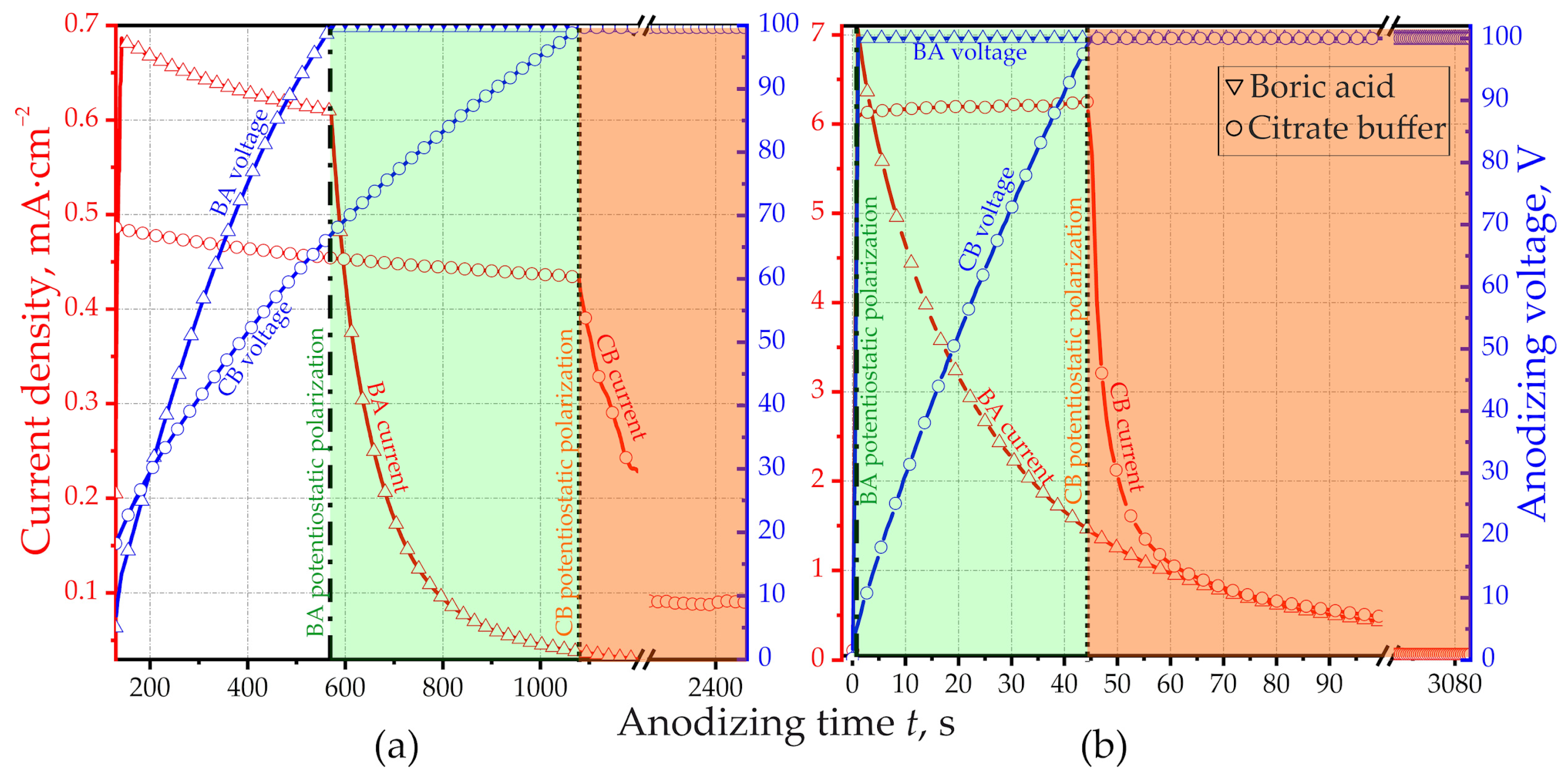
Figure 3.
Dependences of specific charge qAl, q100 and qOx on the anodic current density for alumina obtained in (a) BA and (b) CB (bilogarithmic coordinates).
Figure 3.
Dependences of specific charge qAl, q100 and qOx on the anodic current density for alumina obtained in (a) BA and (b) CB (bilogarithmic coordinates).

Figure 4.
Dependences of specific charge qAl, q100 and qOx on the anodic current density for AlCu4 oxide obtained from (a) BA anodizing and (b) CB anodizing (bilogarithmic coordinates).
Figure 4.
Dependences of specific charge qAl, q100 and qOx on the anodic current density for AlCu4 oxide obtained from (a) BA anodizing and (b) CB anodizing (bilogarithmic coordinates).

Figure 5.
XPS survey of the AlCu4 alloy after (a) 3, (b) 6 and (c) 9 min of sputtering.

Figure 6.
AES element distribution profile of AlCu4 oxide obtained from (а) BA full anodizing at 9.1 mA·cm−2, (c) BA full anodizing at 1.43 mA·cm−2 and (b) BA 100 V anodizing at 1.43 mA·cm−2. In the case of full anodizing, the anodic voltage not only reaches 100 V but also continues to be maintained until the anodic current reaches an infinitesimal value commensurate with the leakage current.

Figure 7.
AES element distribution profile of AlCu4 oxide obtained from (а) CB 100 V anodizing at 1.72 mA·cm−2; (b) CB 100 V anodizing at 12.05 mA·cm−2; (c) CB full anodizing at 1.65 mA·cm−2; (d) CB full anodizing at 11.21 mA·cm−2. In the case of full anodizing, the anodic voltage not only reaches 100 V but also continues to be maintained until the anodic current reaches an infinitesimal value commensurate with the leakage current.

Figure 8.
Anodizing schematic view for (а) BA and (b) CB. I—initial; II—100 V; III—full anodizing.

Figure 9.
Surfaces and cross-sections of porous barrier alumina obtained via BA full galvanostatic anodizing: (а) 0.4 mA·cm−2; (b) 7.0 mA·cm−2.
Figure 9.
Surfaces and cross-sections of porous barrier alumina obtained via BA full galvanostatic anodizing: (а) 0.4 mA·cm−2; (b) 7.0 mA·cm−2.

Figure 10.
Surfaces and cross-sections of barrier alumina obtained via CB full galvanostatic anodizing: (а) 0.4 mA·cm−2; (b) 7.0 mA·cm−2.
Figure 10.
Surfaces and cross-sections of barrier alumina obtained via CB full galvanostatic anodizing: (а) 0.4 mA·cm−2; (b) 7.0 mA·cm−2.

Figure 11.
(a) XPS and (b) study of copper valence state AlCu4 oxide obtained via 100 V CB galvanostatic anodizing at 12.1 mA·cm−2 after 2 min of sputtering.
Figure 11.
(a) XPS and (b) study of copper valence state AlCu4 oxide obtained via 100 V CB galvanostatic anodizing at 12.1 mA·cm−2 after 2 min of sputtering.

Figure 12.
(a) XPS of AlAg5 oxide obtained via CB anodizing, 4 min sputtering Ar+ accelerating 4 kV, area 5 × 5 mm2; (b) subsequent 3 min sputtering Ar+ accelerating 4 kV, area 1.5 × 1.5 mm2.
Figure 12.
(a) XPS of AlAg5 oxide obtained via CB anodizing, 4 min sputtering Ar+ accelerating 4 kV, area 5 × 5 mm2; (b) subsequent 3 min sputtering Ar+ accelerating 4 kV, area 1.5 × 1.5 mm2.

Figure 13.
(a) XPS of AlAg15 oxide obtained via CB anodizing, 4 min sputtering Ar+ accelerating 4 kV, area 5 × 5 mm2; (c) subsequent 3 min sputtering Ar+ accelerating 4 kV, area 1.5 × 1.5 mm2; (b) study of Ag state.
Figure 13.
(a) XPS of AlAg15 oxide obtained via CB anodizing, 4 min sputtering Ar+ accelerating 4 kV, area 5 × 5 mm2; (c) subsequent 3 min sputtering Ar+ accelerating 4 kV, area 1.5 × 1.5 mm2; (b) study of Ag state.

Figure 14.
Dependence of qAl, q100 and qOx on the anodic current density for AlZn3 oxide obtained via (a) BA anodizing and (b) CB anodizing (bilogarithmic coordinates).
Figure 14.
Dependence of qAl, q100 and qOx on the anodic current density for AlZn3 oxide obtained via (a) BA anodizing and (b) CB anodizing (bilogarithmic coordinates).


Table 1.
Heat treatments of aluminum and alloys.
| Material | Heat Treatment | Cooling Modes | |
|---|---|---|---|
| Temperature | Time | ||
| Al | 753 К | 1 h | cold water (293–298 K) |
| AlCu4 | 803 К | 1 h | boiling water (373 K)—5 s, followed by cold water (293–298 K) |
| AlZn3 | 673 К | 1 h | cold water (293–298 K) |
| AlAg5 | 793 К | 1 h | cold water (293–298 K) |
| AlAg15 | 793 К | 1 h | cold water (293–298 K) |
Table 2.
The dependence of copper width accumulation zone on anodizing modes.
| Boric Acid | Citrate Buffer | ||||||
|---|---|---|---|---|---|---|---|
| Current Density, mA сm−2 | 1.4 | 1.4 | 9.1 | 1.7 | 1.7 | 12.1 | 11.2 |
| Duration of anodizing | 100 V | full | full | 100 V | full | 100 V | full |
| Width of accumulation zone, nm | 32 | 65 | 65 | 58 | 68 | 55 | 65 |
Table 3.
Results of Ag-, Cu- and Zn-doped Al2O3.
| Dopant | Alloy | Dopant Concentration | Dopant Oxidation State | Ref. | ||
|---|---|---|---|---|---|---|
| In Alloy | In Metal–Oxide Interface | In Oxide | ||||
| Cu | AlCu4 | 1.7 at.% | ≈10 at.% | ≈0.4–0.7% ([Cu]/([Cu] + [Al])) | +1 or non-oxidized | this work |
| Cu | AI–3.5 Cu | 1.5 at.% | ≥2.7–3.7 at.% | no numerical data | not determined | Ref. [54] |
| Cu | Al–1.5 wt.% Cu | 0.58–0.64 at.% | ≈40 at.% | 0.25–0.28 at.% | not determined | Ref. [57] |
| Cu | Al–0.4 at.% Cu | 0.4 at.% | 9% ([Cu]/([Cu] + [Al])) | no numerical data | not determined | Ref. [55] |
| Cu | Al–1 at.% Cu | 1 at.% | 14% ([Cu]/([Cu] + [Al])) | no numerical data | +2 | Ref. [56] |
| Cu | Al–1 at.% Cu | 1 at.% | 33.3 at.% | 0.20–0.32 at.% | +2 | Ref. [65] |
| Cu | AA2024-T3 | 1.97 at.% | not analyzed | 0.17–0.4 at.% | not determined | Ref. [42] |
| Mg | 1.76 at.% | not analyzed | 0.30–0.43 at.% | |||
| Cu | 2024 | 3.8–3.9 wt.% | not analyzed | not detected | not determined | Ref. [29] |
| Ag | AlAg5 | 1.3 at.% | no numerical data | below the detection limit | undetermined | this work |
| Ag | AlAg15 | 4.05 at.% | no numerical data | the atomic ratio of silver to aluminum in oxide is 0.1 times that in the alloy | +1 | this work |
| Ag | AlAg | 0.3 at.% | ≈3.1 × 10¹⁵ Ag atoms·cm−2 | the atomic ratio of silver to aluminum in oxide is between 0.3 and 0.9 times that in the alloy | +1 | Ref. [61] |
| 0.6 at.% | +1 | |||||
| 0.9 at.% | +1 | |||||
| 1.2 at.% | +1 | |||||
Disclaimer/Publisher’s Note: The statements, opinions and data contained in all publications are solely those of the individual author(s) and contributor(s) and not of MDPI and/or the editor(s). MDPI and/or the editor(s) disclaim responsibility for any injury to people or property resulting from any ideas, methods, instructions or products referred to in the content. |
© 2024 by the authors. Licensee MDPI, Basel, Switzerland. This article is an open access article distributed under the terms and conditions of the Creative Commons Attribution (CC BY) license (https://creativecommons.org/licenses/by/4.0/).
Share and Cite
MDPI and ACS Style
Poznyak, A.; Knörnschild, G.; Hoha, A.; Pligovka, A. Porous and Ag-, Cu-, Zn-Doped Al2O3 Fabricated via Barrier Anodizing of Pure Al and Alloys. Coatings 2024, 14, 576. https://doi.org/10.3390/coatings14050576
AMA Style
Poznyak A, Knörnschild G, Hoha A, Pligovka A. Porous and Ag-, Cu-, Zn-Doped Al2O3 Fabricated via Barrier Anodizing of Pure Al and Alloys. Coatings. 2024; 14(5):576. https://doi.org/10.3390/coatings14050576
Chicago/Turabian StylePoznyak, Alexander, Gerhard Knörnschild, Aliaksandr Hoha, and Andrei Pligovka. 2024. "Porous and Ag-, Cu-, Zn-Doped Al2O3 Fabricated via Barrier Anodizing of Pure Al and Alloys" Coatings 14, no. 5: 576. https://doi.org/10.3390/coatings14050576
Note that from the first issue of 2016, this journal uses article numbers instead of page numbers. See further details here.