
The Individual Drive of a Wheelset and the Problematics of Its Electromechanical Phenomena

Department of Automotive, Combustion Engines and Railway Engineering, Faculty of Mechanical Engineering, CTU in Prague, Technická 4, 16000 Prague, Czech Republic
*
Author to whom correspondence should be addressed.
Vehicles 2024, 6(2), 814-831; https://doi.org/10.3390/vehicles6020039
Submission received: 8 March 2024
/
Revised: 19 April 2024
/
Accepted: 26 April 2024
/
Published: 4 May 2024
(This article belongs to the Special Issue Railway Vehicles and Infrastructure)
Abstract
:This paper deals with the phenomenon of torsion oscillations in railway vehicle drive systems. The main goal is to reduce the risk of presence of torsional oscillations in wheelset drive, eventually to propose systems to effectively identify and eliminate torsional oscillations of wheelsets. Therefore, a simulation wheelset drive model including a detailed model of the asynchronous traction motor control was built. The results of computer simulations show that the torsional oscillations can be effectively eliminated by avoiding the resonance states between the excitation frequencies given by pulse width modulation of the inverter and the eigenfrequencies of the mechanical part of the drive. Furthermore, it was found that the presence of torsional oscillations of the wheels can be detected based on the traction motor current ripple. The wheelset drive model was subsequently implemented in a simulation model of a four-axle locomotive. A new algorithm of an anti-slip protection system that utilizes motor currents was implemented in the model. Simulations show that such an anti-slip protection system can prevent the occurrence of undesired large amplitude of wheelset torsional oscillations. The models and simulation results are presented in detail in the paper.
1. Introduction
In terms of development of traction drives for modern rail vehicles, efforts have generally been aimed at more efficient and powerful systems. Increasing the power up to theoretical physical limits (meaning especially adhesion limits) also reveals new negative physical phenomena. Torsional oscillations of traction drive components, which are discussed in this paper, play an important role among these undesirable effects.
Recently, problems with Deutsche Bahn locomotives class 145 (Bombardier TRAXX family) have surfaced. The relative rotation of the wheel disc with respect to the wheelset axle has been observed within locomotive maintenance (see Figure 1) [1]. Such slip indicates failure of the press-fitted joint that holds the wheel and the axle together. This means the friction between two parts is reduced enough to allow the wheel to freely rotate or shift along the axis for a short time.
This condition can be dangerous, especially in situations when the vehicle passes through a curve or railroad switch. At that moment, significant transversal forces which act in contact with a wheel flange and rail head [2] may cause a shift in the wheel along the axis, thus pushing the wheels closer to each other. This leads to a decrease in the lateral distance between wheels, e.g., back-to-back dimension, as schematically presented in Figure 2. If the distance between wheels decreases under limit values, the vehicle can derail.
As the most probable reason for such shifts, the phenomenon of torsion oscillations was assumed. An effort to investigate the occurrence of torsional oscillations motivated the research in the area of traction drives of modern locomotives and other high-power rail vehicles. Mathematical simulation models are usually used as the principal research tool. Complex simulation models of a whole railway vehicle were presented by Markovic et al. [3] and Trimpe et al. [4]. The research in the field of torsion oscillations in traction drives of railway vehicles focuses on the development of control systems, which are used for an elimination of undesired behaviour of traction drives during the vehicle operation, for example, anti-slip control systems [5]. However, many other control systems can be utilized in modern traction drive systems. Efforts in this research area include controllers and control systems for solving dynamic issues with an adhesion loss and re-gain [6,7], control systems for an active reduction of vibrations and noise [8,9,10], predictive slip control systems [11] or systems applying advantages of fuzzy logic for anti-slip control against classic Proportional-Integral-Derivative (PID) controllers [12]. Another area of research of torsion oscillations of traction drives focuses on the investigation of dynamic loading of mechanical parts of drive trains of railway vehicles.
This research focuses especially on dynamic loading of wheelsets and its relationship to electrical parameters of the drive train. In [13], self-excited torsion oscillations of the wheelset were analysed. The same problematics from the perspective of an adhesion loss were analysed by Liu et al. [14], utilizing a simulation model of a wheelset drive with two degrees of freedom. Qi and Dai in [15] focused on the electro-mechanical coupling between harmonic components of the traction motor torque and the wheel wear, whereas in [16], the influence of traction dynamics on the wheel polygonization was analysed. The negative impacts of electro-mechanical coupling in the asynchronous motor drive systems were investigated by Winterling [17], who examined complex dynamic behaviour of drive systems of locomotives. Szolc et al. [18] focused on dynamic electro-mechanical coupling effects in machine systems driven by asynchronous motors. The system analysis presented by Schneider [19,20] describes the effects of a wheelset overloading caused by the combined load from torsion oscillations and acting lateral forces. The importance of the research of the harmonic components was also pointed out by Takahashi et al. [21], who focused specifically on the efficiency of traction motors for railway vehicles, or in the work of Lu et al. [22], which proves, that pulsating motor torque has significant influence on the wheel-rail contact forces and longitudinal and vertical vibrations within the vehicle bogie.
The work presented in this paper utilizes a complex model of the drive system of a locomotive. Unlike the works published so far, special emphasis is placed on two innovative ideas: elimination of torsion system resonances via torsional stiffness optimization and improving the sensitivity of the traction motor control system to the detection of presence of torsional oscillations using observation of traction motor phase currents.
2. Object of Interest
The parameters of the mathematical models in this study are based on the design of modern four-axle locomotives. These locomotives are equipped with a pair of traction bogies, both with two individually powered wheelsets. The asynchronous traction drives provide overall power output between 6 and 7 MW. Typical representatives of this category of locomotives are Siemens ES64U4, Siemens Vectron, or Skoda 109E (Figure 3).
Mathematical modelling was realized in two steps. In the first step, simulations were performed with a wheelset drive model containing a torsional-flexible system of a single wheelset and its electrical drive. In the second step, a model of a whole vehicle was utilized. The vehicle model uses the wheelset drive models and moreover includes a detailed model of the mechanical system of the whole vehicle with implemented real external conditions such as adhesion, drive resistances, and track irregularities. These two mathematical models, namely the wheelset drive model and vehicle model, respectively, are described in the sections below.
2.1. Simulation Model of the Wheelset Drive
A complete drive of any railway vehicle is an extensive system. The model of the wheelset traction drive is split into four main groups which define four main sub-models—a mechanical part, an electrical-control part, a wheel-rail contact and a train drive dynamics model.
The connection of these four sub-models creates the whole wheelset model. A scheme representing sub-models and their relations (outputs/inputs) is shown in Figure 4. This model of a single drive was created within Matlab Simulink R2017a software.
2.1.1. Mechanical Part
A fully suspended hollow shaft drive (see Figure 5) is addressed in this study. Such a design allows decreasing unsprung masses and forces resulting from track irregularities, which is important for higher velocities of railway vehicles within tracks of common quality. The mechanical part of the wheelset drive consists of these main parts:
- rotor of the traction motor,
- gearbox with a pinion and a gearwheel,
- hollow shaft with elastic articulations/clutch/coupling,
- wheelset consisting of an axle and wheels.
The fully suspended wheelset drive is schematically presented in Figure 6. For the purpose of mathematical description, the mechanical part of wheelset drive was divided in to seven rotational masses mutually connected by torsion springs designated as kt. Thus, it forms a torsion system with seven degrees of freedom.
2.1.2. Electrical Part—Generation and Control of Torque
The electrical part is focused on the traction motor and its control. An asynchronous motor is considered. The mathematical description corresponds to voltage-flux Equations (1)–(8):
where u1 is stator voltage, i1 is stator current, Ψ1 is stator flux, R1 is stator ohmic resistance, u2 is rotor voltage, i2 is rotor current, Ψ2 is rotor flux, R2 is rotor ohmic resistance, pp is number of pole pairs, and ωm is rotor mechanical angular speed. Voltage equations, particularly (3) and (4), contain angular speed of the rotor, ωm, which means there is a relation between electrical and mechanical values in the motor.
Stator and rotor flux are given by currents and inductances, as defined in Equations (5)–(8):
where L1 is stator inductance, L2 is rotor inductance, and Lh is coupled inductance.
Resulting torque Equation (9) is derived from the previous Equations (1)–(8):
where M is the motor torque
The input for the motor control is the required torque of the motor. The output from the motor control is the mechanical torque of the motor. The control is based on the vector control scheme which is shown in Figure 7. Such an approach allows us to control alternate current machine with direct current values (currents) similar to direct current motors, where torque is proportional to the direct current within a certain range of rotor speed.
The required value of torque is determined from the actual requirement for velocity of the vehicle, which is also controlled via an anti-slip protection block. This block permanently checks angular velocities and angular accelerations of all wheelsets (in fact, rotors) and via mutual comparison determines the occurrence of excessive slippage or loss of adhesion. This control is included in the controller’s block of the electrical model (see brown rectangle in Figure 7). The other parts of the electrical model in Figure 7 are: decoupling block (black rectangle), coordinate systems transformation block (orange rectangle), pulse-width modulation (PWM) block (green rectangle), supply voltage block (yellow rectangle), inverter block (blue rectangle), asynchronous motor (ASM) block (red rectangle) and ASM model block (violet rectangle).
2.1.3. Wheel-Rail Contact—Adhesion Model
The maximum tangential force transmissible in a wheel-rail contact T is given by Equation (10):
where µ is the adhesion coefficient and Q is the vertical force, i.e., the wheel force.
The calculation of the adhesion coefficient µ is based on the adhesion theory of Polach [27], considering minor updates allowing wider variability for the setting of friction parameters. The resulting adhesion coefficient µ applied within the wheelset drive model in dependence on the relative slip and vehicle velocity is presented in Figure 8.
The longitudinal slip sx is defined as a division of slip speed and vehicle speed according to Equation (11), where rk is the rolling radius of the wheel, ωk is the angular speed of the wheel, and v is the velocity of the vehicle:
The range of velocities of 5–20 m·s−1 corresponds to the range of running velocities of the vehicle at which the traction motors are able to develop maximum torque. At higher running speeds, the torque of the traction motors is limited by the maximum power output.
2.1.4. Train Drive Dynamics—Velocity Calculation
This submodel calculates analytical formulas from the traction mechanics to provide the velocity of a simulated vehicle run. The calculations are based on the balance between accelerating forces and resistance forces. The difference between these forces determines the resulting longitudinal force acting on the vehicle, which in the relation to the mass of the vehicle results in acceleration, a. The final product of these calculations is the speed of the modelled train, v (Equation (12)), which is the result of the time integration of the initial speed v0 and acceleration a.
2.2. Simulation Model of the Vehicle
Using the wheelset drive model, the vehicle model was built (Figure 9). The vehicle model contains all important components reflecting the drive scheme in Figure 5 and other vehicle features such as suspension, bogie frame, carbody etc. The mechanical part of the vehicle model was built within SIMPACK 2019 software. This software also considered an adhesion model and other outer conditions (drive resists, track irregularities, track curvatures etc.). Electrical and control parts of the model were taken from the wheelset model.
3. Simulation Results
3.1. Electromagnetic Excitation and Torsion Vibrations
For purposes of the research explained in this section, the wheelset model of the single drive was utilized. The fundamental behaviour of the three-phase asynchronous traction motor supplied from the inverter could be explained on its one winding phase. The phase current is rippled. The essence of the traction motor current ripple Δid (see Figure 10 and Equations (13)–(17)), is described in the literature, e.g., [28].
When the switch is ON, the supply voltage U1 is put on the L-R-Ui load, and in the circuit there is an immediate direct voltage ud and direct current id increase according to Formulas (13) and (14):
where R is ohmic resistance, L is inductance, t is time, dt is a time derivative, I01 is the initial value of direct current, I02 is the final value of direct current, and τd is the machine time constant. The induced voltage Ui is induced in the load as one of its characteristics.
When the switch is OFF there is no supply voltage U1 on the load. In the circuit, there is no immediate direct voltage ud, and the direct current id decreases according to Equations (15)–(17). Only the induced voltage Ui in the load is present:
A real asynchronous motor supplied from an inverter has a rippled current by many harmonics, including the switching frequency and its multiples, the first harmonic of the supplying voltage and its multiples, frequency sidebands etc. Harmonic components are the source of the excitation of torsion vibrations in the mechanical part of the traction drive. More specifically, the current ripple causes the ripple of the electromagnetic torque. The excitation frequencies of the inverter were determined in accordance with [29] by Equations (18) and (19):
- For odd multiples of the switching frequency fPWM:where: f1 is the first harmonic of the supply voltage,(i = 1, 2, 3, …); (k = 1, 3, 5, …); (l = 1, 2, 3, 4, …);
- For even multiples of the switching frequency fPWM:where: (i = 1, 2, 3, …); (m = 2, 4, 6, …); (n = 0, 1, 2, 3, …)
The basic simulation and modal analysis of the torsion system provide essential information about eigenfrequencies, content of harmonics (excitation frequencies involved in the electromagnetic torque of the traction motor) and their resulting potential resonance states. This complex knowledge is presented via Campbell’s diagram (Figure 11), which shows six eigenfrequencies of the torsion system (from the second the seventh, as the first eigenvalue corresponds to the natural rotation of the torsion system), ten excitation frequencies (from the third multiple of the first harmonics f1 through multiples of switching frequencies and their side bands) and five potential resonances (from I to V). Further simulations were focused on the pinion and its respective resonance states:
- III—resonance of the fifth eigenfrequency with the frequency sideband of the switching frequency fPWM.
- V—resonance of the seventh eigenfrequency with the frequency sideband of the third multiple of the switching frequency fPWM.
To study these resonance states, simulations of the acceleration of the vehicle from 0 kmh−1 up to the speed of 86 kmh−1 (approx. 23.8 ms−1, ωR = ωP ≈ 165 rads−1) were performed. During the simulations, the following limitations of traction drive were applied: the maximal change in the traction motor drive torque over time was 1000 Nms−1, with maximal traction motor torque of 8000 Nm in the whole speed range. Figure 12 presents the course of the pinion driving torque within this simulation with an excited resonance in the time around 27 s.
The area of resonance formation marked by the red rectangle in Figure 12 was analysed by Fast Fourier Transformation (FFT) analysis (Figure 13).
During the drive through the speed spectrum, very significant torsion vibrations were excited. The FFT analysis revealed that these enormous vibrations have a frequency of 568 Hz, which is close to the fifth eigenfrequency of the torsion system. The excitation frequency of the sideband is 570 Hz, which provideds evidence of excitation of the supposed resonance state III.
To investigate the harmonics with respect to speed, simulations were carried out for vehicle speeds of 10 kmh−1, 25 kmh−1, 52 kmh−1, 75 kmh−1 and 86 kmh−1 (Figure 14). The figure shows increasing magnitudes, which were expected. The most dominating component is the third multiple of f1.
In the context of Figure 14, the first way of elimination is to optimize the fifth eigenfrequency via change in torsion stiffness ktR—which represents stiffness of the shaft between the rotor and pinion. The excitation magnitudes decrease with decreasing speed, and therefore, the potential of harmonic components which could excite a resonance state decreases as well. This leads to the increase in ktR and the eigenfrequency in this case. The resonance state excitation can also be eliminated by moving the specific eigenfrequency into lower values, i.e., out of the excitation frequency range.
The set of simulations for modified ktR and respective fifth eigenfrequency was carried out as presented in Figure 15. The stiffness ratio is defined towards the nominal value applied in the first simulation (Figure 13).
The approach to eliminate the resonance for the fifth eigenfrequency via moving it out of the range of excitation frequencies is supported by the Campbell diagram, which indicates that the fifth eigenfrequency should be under 560 Hz. As the asynchronous motor works with a slip, the stiffness was set up for ktR1 up to 85%.
The second way of elimination of resonance states was tested via a set of simulations for the torsion stiffnesses from 105% to 205%. It was assumed to reduce the potential of excitation harmonic components by increasing the eigenfrequencies. Figure 16 shows the result of this set of simulations and the fact that the excited resonance state of the pinion loading torque was significantly reduced by that approach. Equivalent results were reached by the reduction in torsion stiffness (from 85% to 90%). The Figure 17 summarizes results of FFTs from these simulations with respect to maximum magnitudes of excited resonance states.
It is clear that with increasing of the stiffness ktR, the magnitude of the studied harmonic component decreases, as well as when the eigenfrequency is moved out of the range of excitation frequencies via decreasing of the stiffness ktR. This is the conclusion which confirms the initial assumption for carrying out the simulations.
3.2. Phenomena Occurring during Loss of Adhesion
Another situation with a high potential for torsional oscillations is running a wheelset on the limit of adhesion and sudden decrease in friction between wheel and rail. Two cases of such a situation can be distinguished:
- the wheelset loses its adhesion instantly (prestressed components such as an axle may quickly release its torsion energy);
- the wheelset loses its adhesion gradually (energy accumulated in the wheelset is gradually released).
The first situation usually leads to rapid acceleration of the wheelset (likewise the rotor of traction motor) and relatively quick reaction of the anti-slip protection. The second situation is considerably harder to recognize. The axle usually starts to oscillate on one end, but the other wheel still holds the adhesion, so the wheelset as a whole does not accelerate to higher speeds. Absence of rapid change then results in undesirable delays in the reaction time of the anti-slip protection system. Such a situation is shown in Figure 18. At time 15 s, the adhesion of the right wheel W1 (see Figure 7) decreases from 0.4 to 0.2, and the wheelset subsequently starts to oscillate within maximum torsion amplitudes up to 0.02 rad (corresponding to approximately 1 degree). The anti-slip protection system recognizes the non-standard behaviour of the drive around time 17 s and decreases engine torque, which leads to gradual disappearance of wheelset oscillations.
Such oscillations are observable via phase currents of the asynchronous motor. Figure 19 shows time course of phase current i1q, both as an absolute value (solid line) and as a filtered value (dashed line). It is noticeable that the current starts to ripple significantly between the time of 16 and 16.5 s. The torsional oscillations of the wheelset increase undisturbed up to the time of 16.8 s, when anti-slip protection reacts and decreases torque of the motor, which also causes the disappearance of the oscillations.
The important fact is a correlation between frequencies of wheelset oscillations and oscillations of phase current i1q, which is the result of the presence of angular velocity in the voltage equation of asynchronous motors (4). Frequencies are identical as can be seen in Figure 20, which means that the wheelset oscillations can be identified via observation of electrical values. This allows us to check actual state of the wheelset (whether it is oscillating or not).
This approach allows us to implement an additional block into the control scheme of the drive that monitors the phase currents of the motor in order to detect the presence of oscillations in the wheelset. This block is able to recognize the wheelset oscillations earlier then a standard anti-slip protection system.
A set of simulations was performed in order to prove the relation between mechanical and electrical oscillations in the drive. The simulations were focused on the situation of the loss of adhesion on the left or right wheel considering different velocities of the vehicle and different amounts of motor torque. The range of motor torques was between 60 and 100% of the maximum value.
Comparison of mechanical and electrical oscillations allows us to determine the relation between them, which is shown in Figure 21. It can be seen that the relation between the amplitudes of the motor current and the wheelset oscillations is almost linear. This applies to slippage on both (left and right) wheels. Using these linear dependencies, it is possible to assess whether the wheelset oscillations detected by the oscillations of the motor currents are harmful or not.
3.3. Simulations of Vehicle Model
The wheelset model was utilized in the vehicle model. The control structure containing standard anti-slip protection shown in Figure 4 was upgraded with a part measuring and evaluating values of motor phase currents. This was done in order to recognize the appearance or evolution of mechanical oscillations into higher values. These oscillations cause enormous load to the axle and other components of the drive, but the anti-slip protection does not detect them. The system is able to recognize a situation when the wheelset has completely lost adhesion and starts to accelerate together with the rest of the drive, but not the situation when the wheelset oscillates. This is due to fact the anti-slip protection compares angular speeds and angular accelerations of all rotors. When one of the rotors rotates much faster than the others, the control block evaluates this as a slippage and reduces torque of the motor. A similar situation occurs when one of the rotors starts to accelerate faster than the others, or when the acceleration exceeds physically real values.
Regardless of whether the wheelset starts to accelerate or not, oscillations of one wheel always transfer through the drivetrain into the rotor and influence electrical values of the motor itself. Observing the motor current may help recognize situations when the wheelset oscillates. This may be a source of the information for a quicker reaction of the anti-slip protection and a reduction in oscillations.
A comparison between standard and updated controls is shown in Figure 22. This figure shows time courses of original and updated settings, considering the same bounding conditions of a vehicle running through the curve. The wheelset starts to oscillate between 15.5 s and 17.75 s. Additional information about the presence of oscillations allows decreasing the torque faster by approximately 0.2 s, so oscillations amplitudes cannot evolve to higher values. Therefore, it is possible to reduce significantly high amplitudes of oscillations that occur in the wheelset—approximately to 20% of the original value, similarly to time duration of the phenomenon.
The important aspect is that such an upgrade of drive control is mainly a software task without the necessity for any design changes in mechanical and power parts of the wheelset drive. Therefore, this approach may be relatively easily implemented on already running vehicles that are operated frequently and thus spare significant costs connected with the presence of torsion oscillations.
4. Conclusions
Wheelset torsional oscillations are an undesirable and potentially very dangerous phenomenon. Present anti-slip systems are not capable of effectively detecting and eliminating such torsional oscillations.
Computer simulations realized with the wheelset drive simulation model revealed that harmonic components of the electromagnetic torque of the asynchronous traction motor can excite significant torsion vibrations, which cause torsion overloading of the mechanical components. Such problems can be eliminated by optimizing the eigenfrequencies of mechanical parts of the wheelset drive by modifying torsion stiffnesses of coupling elements. Furthermore, it was found that the presence of torsional oscillations of the wheels can be detected based on the traction motor current ripple. This finding was used in the design of a new algorithm of anti-slip protection system. This algorithm was implemented on a four-axle locomotive model.
The simulations proved that wheelset torsional oscillations can be observed in advance within currents of the asynchronous traction motor. Our results showed that the improved anti-slip protection, implementing identification of torsion vibrations via motor currents, reacts faster and enables preventing the loss of traction and development of large amplitudes of torsion oscillations jeopardizing a wheelset. This new algorithm for anti-slip protection can also be implemented in software of vehicles that are already in operation and for which any changes in their mechanical design are very difficult, if not impossible.
Author Contributions
Conceptualization, T.F., J.K. and V.D.; methodology, T.F. and V.D.; software, T.F. and V.D.; validation, T.F. and V.D.; formal analysis, T.F. and V.D.; investigation, T.F. and V.D.; resources, T.F. and V.D.; data curation, T.F., J.K. and V.D.; writing—original draft preparation, T.F., J.K. and V.D.; writing—review and editing, T.F., J.K. and V.D.; visualization, T.F., J.K. and V.D.; supervision, J.K.; project administration, T.F., J.K. and V.D.; funding acquisition, T.F., J.K. and V.D. All authors have read and agreed to the published version of the manuscript.
Funding
This research was funded by The Technology Agency of the Czech Republic, programme National Competence Centres, project # TN01000026 Josef Bozek National Center of Competence for Surface Transport Vehicles and by The Czech Technical University and a related grant (No. SGS20/120/OHK2/2T/12).
Data Availability Statement
Data are contained within the article.
Acknowledgments
Support from the tutor of both authors, Doc. Ing. Josef Kolář, CSc., is gratefully acknowledged for both theoretical and practical components of the research. Support during laboratory activities from Ing. Petr Bauer, is acknowledged.
Conflicts of Interest
The authors declare no conflict of interest.
References
- Kadeřávek, P.; Pernička, J. Torsion oscillations of powered wheelsets. Railvolution 2013, 7, 34–37. [Google Scholar]
- Anand, P. Coning of Wheels in Railways: Theory and Purpose. Available online: https://civildigital.com/coning-wheels-railways-theory-purpose/ (accessed on 22 June 2023).
- Markovic, P.; Kostic, D.; Bojovic, N. One Method for Detection of Torsional Oscillations of Driving Axles of Electrical Locomotives. In Proceedings of the PRORAIL 2015—XXII. Medzinárodná Konferencia Súčasné Problémy v Koľajových Vozidlách, Žilina, Slovakia, 16–18 September 2015; Žilinská Universita, Strojnická Fakulta: Žilina, Slovakia, 2015; Volume 2, pp. 27–37. [Google Scholar]
- Trimpe, F.; Lück, S.; Naumann, R.; Salander, C. Simulation of Torsional Vibration of Driven Railway Wheelsets Respecting the Drive Control Response on the Vibration Excitation in the Wheel-Rail Contact Point. Vibration 2020, 4, 30–48. [Google Scholar] [CrossRef]
- Kondo, K. Anti-slip Control Technologies For the Railway Vehicle Traction. In Proceedings of the 2012 IEEE Vehicle Power and Propulsion Conference, Seoul, Republic of Korea, 9–12 October 2012; pp. 1306–1311. [Google Scholar] [CrossRef]
- Sebesan, I.; Mitu, A.; Sireteanu, T. On the stick-slip phenomena in traction railway vehicles. Proc. Rom. Acad. Ser. A 2015, 16, 209–2016. [Google Scholar]
- Wu, G.; Shen, L.; Yao, Y.; Song, W.; Huang, J. Determination of the dynamic characteristics of locomotive drive systems under re-adhesion conditions using wheel slip controller. J. Zhejiang Univ. A 2023, 24, 722–734. [Google Scholar] [CrossRef]
- Reitmeier, D.; Mertens, A. Active Reduction of Gear Mesh Vibrations by Drive Torque Control. In Proceedings of the 2023 IEEE International Conference on Mechatronics (ICM), Loughborough, UK, 15–17 March 2023. [Google Scholar] [CrossRef]
- Fleischer, M. Modal State Control in the Frequency Domain for Active Damping of Mechanical Vibrations in Traction Drive-Trains. In Proceedings of the 8th IEEE International Workshop on Advanced Motion Control, 2004. AMC ’04, Kawasaki, Japan, 28 March 2004. [Google Scholar]
- Abouzeid, A.; Trimpe, F.; Lück, S.; Traupe, M.; Guerrero, J.; Briz, F. Co-Simulation-Based Verification of Torsional Vibration Protection of Electric-Driven Railway Vehicle Wheelsets. Vibration 2020, 5, 613–627. [Google Scholar] [CrossRef]
- Sadr, S.; Khaburi, D.; Rodriguez, J. Predictive Slip Control for Electrical Trains. IEEE Trans. Ind. Electron. 2016, 63, 3446–3457. [Google Scholar] [CrossRef]
- Hajano, F.; Abro, F.; Memon, T.; Kalwar, I.; Burhan. Fuzzy Logic based Anti-Slip Control of Commuter Train with FPGA Implementation. Int. J. Adv. Comput. Sci. Appl. 2020, 11, 293–300. [Google Scholar] [CrossRef]
- Breuer, W.; Yu, M. Energie-Methode: Vorhersage des maximalen dynamischen Torsionsmomentes. In Proceedings of the 16. Internationale Schienenfahrzeugtagung Dresden, Dresden, Germany, 12–14 September 2018. [Google Scholar]
- Liu, J.; Zhao, H.; Zhai, W. Mechanism of self-excited torsional vibration of locomotive driving system. Front. Mech. Eng. China 2010, 5, 465–469. [Google Scholar] [CrossRef]
- Qi, Y.; Dai, H. Influence of motor harmonic torque on wheel wear in high-speed trains. J. Rain Rapid Transit 2020, 234, 32–42. [Google Scholar] [CrossRef]
- Spangenberg, U.; Fröhling, R. Solving locomotive wheel polygonization by reducing variable frequency drive interharmonics. Proc. Inst. Mech. Eng. Part F J. Rail Rapid Transit 2021, 235, 73–82. [Google Scholar] [CrossRef]
- Winterling, M. Oscillations in Rail Vehicle Traction Drives, Analysis of Electromechanics. Ph.D. Thesis, Delft University, Delft, The Netherlands, 1997; p. 193. [Google Scholar]
- Szolc, T.; Konowrocki, R.; Michajlow, M.; Pregowska, A. An investigation of the dynamic electromechanical coupling effects in machine drive systems driven by asynchronous motors. Mech. Syst. Signal Process. 2014, 49, 118–134. [Google Scholar] [CrossRef]
- Schneider, R. Torsionsschwingungen von Radsatzwellen—Systemanalyse Teil 1: System-und Modellbeschreibung. ZEVrail 2017, 141, 452–461. [Google Scholar]
- Schneider, R. Torsionsschwingungen von Radsatzwellen—Systemanalyse Teil 2: Physikalische Untersuchungen und Sicherheitsbetrachtung. ZEVrail 2018, 142, 27–39. [Google Scholar]
- Takahashi, A.; Sugimoto, S.; Tamiya, S.; Fujii, K.; Endo, M. High-Efficiency Technology for Railway Vehicle Traction Motors. In Proceedings of the 23rd International Conference on Electrical Machines and Systems (ICEMS), Hamamatsu, Japan, 24–27 November 2020; pp. 2114–2117. [Google Scholar] [CrossRef]
- Lu, B.; Liu, Z.; Wang, X.; Song, Y.; Zhang, Q.; Wu, S.; Tao, G. Influence of Electric Traction Drive System Harmonics and Interharmonics on the Vibration of Key Locomotive Components. IEEE Trans. Veh. Technol. 2023, 72, 12830–12844. [Google Scholar] [CrossRef]
- Švestka, D. Atlas Locomotive. Available online: http://www.atlaslokomotiv.net/loko-380.html (accessed on 7 March 2024).
- Dybala, V.; Šulc, B. Simulation of Influence of Transverse Wheel-Set Movement on Torsion Oscillations. In Sborník Vědeckých Prací Vysoké Školy Báňské—Technické Univerzity Ostrava, Řada Strojní; VŠB - Technická univerzita Ostrava: Ostrava, Czech Republic, 2019. [Google Scholar]
- Kolář, J. Design of a Wheelset Drive. Trans. Electr. Eng. 2015, 4, 11–19. [Google Scholar]
- Dybala, V. Simulace zvlnění elektromagnetického momentu asynchronního trakčního motoru lokomotivy napájeného ze střídače. In Sborník Konference STČ na Strojní Fakultě ČVUT v Praze; ČVUT v Praze, Fakulta Strojní: Praha, Czech Republic, 2019. [Google Scholar]
- Polach, O. Creep forces in simulations of traction vehicles running on adhesion limit. In Proceedings of the 6th International Conference on Contact Mechanics and Wear of Rail/Wheel Systems, Göthenburg, Sweden, 10–13 June 2003. [Google Scholar]
- Javůrek, J. Regulace Moderních Elektrických Pohonů; Grada Publishing, a.s.: Praha, Czech Republic, 2003. [Google Scholar]
- Novák, J.; Chyský, J. Vyšetřování ztrát sinusových filtrů pro frekvenčně řízení pohony. In Proceedings of the XXXIII. Celostátní konference o Elektrických Pohonech, Plzeň, Czech Republic, 11 – 13 June 2013. [Google Scholar]
- Dybala, V. The electromagnetically excited resonance of the pinion in fully-suspended drive of a locomotive and its sensitivity on the rotor shaft stiffness. In Proceedings of the STČ 2021—Konference Studentské Tvůrčí Činnosti, Praha, Czech Republic, 4 May 2021. [Google Scholar]
- Fridrichovský, T. Vztah mechanických a elektrických veličin v pohonech moderních kolejových vozidel. In Současné Problémy V Kolejových Vozidlech 2021: XXV. Konference S Mezinárodní Účastí, Sborník Příspěvků; Univerzita Pardubice, Dopravní Fakulta Jana Pernera: Česká Třebová, Czech Republic, 2021; pp. 55–62. [Google Scholar]
Figure 1.
Relative motion of the wheel and the axle. See the mismatch in yellow mark [1].
Figure 1.
Relative motion of the wheel and the axle. See the mismatch in yellow mark [1].

Figure 2.
Schematic representation how wheel distance can decrease due to one-side wheel shift. In this case, the loss of connection occurs for the left wheel.
Figure 2.
Schematic representation how wheel distance can decrease due to one-side wheel shift. In this case, the loss of connection occurs for the left wheel.

Figure 3.
Modern asynchronous locomotive: Skoda 109E (preliminary design) [23].
Figure 3.
Modern asynchronous locomotive: Skoda 109E (preliminary design) [23].

Figure 4.
Wheelset model—scheme of the structure with main parts [24].
Figure 4.
Wheelset model—scheme of the structure with main parts [24].
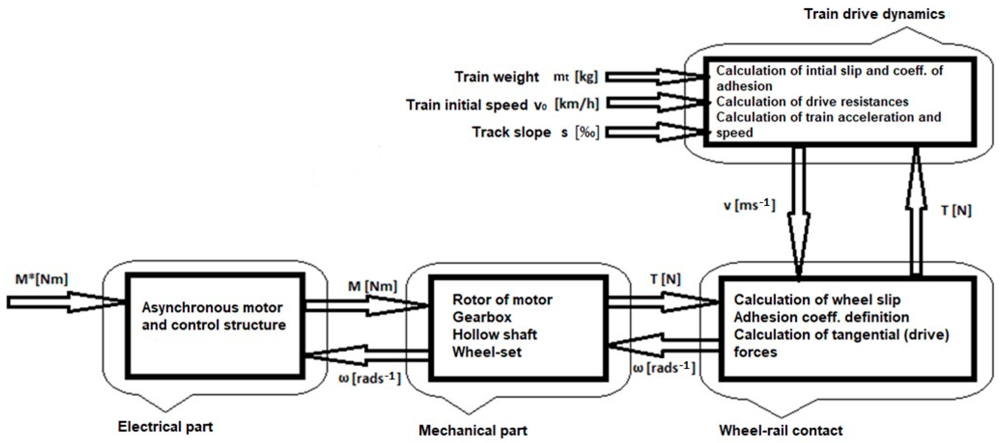
Figure 5.
Cross-section of a modern, fully suspended drive of a locomotive [25].
Figure 5.
Cross-section of a modern, fully suspended drive of a locomotive [25].

Figure 6.
Schematic representation of a fully suspended drive - R—rotor, G1—pinion, G2—gear wheel, C2—right coupling, C1—left coupling, W2—left wheel, W1—right wheel.
Figure 6.
Schematic representation of a fully suspended drive - R—rotor, G1—pinion, G2—gear wheel, C2—right coupling, C1—left coupling, W2—left wheel, W1—right wheel.

Figure 7.
Vector control scheme [26].
Figure 7.
Vector control scheme [26].

Figure 8.
Friction characteristics showing the relation between the slip and the friction coefficient for different velocities of a vehicle.
Figure 8.
Friction characteristics showing the relation between the slip and the friction coefficient for different velocities of a vehicle.

Figure 9.
Models of the bogie (a) and the whole vehicle (b) as shown in MBS software SIMPACK.

Figure 10.
Pulse inverter scheme and the course of the output voltage and the current.
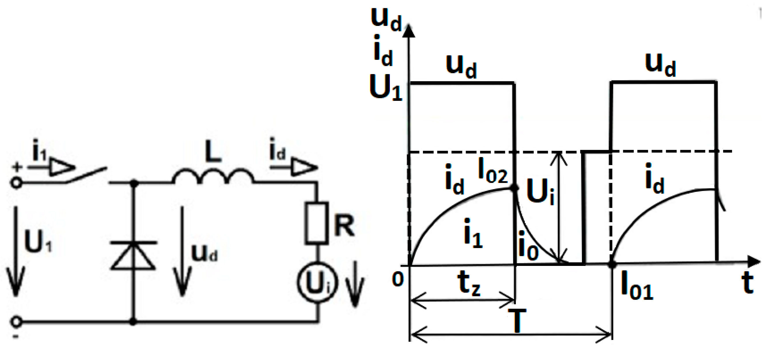
Figure 11.
Campbell diagram.

Figure 12.
Driving torque of the pinion.

Figure 13.
Driving torque of the pinion—FFT analysis.

Figure 14.
Harmonic components magnitude function [30].
Figure 14.
Harmonic components magnitude function [30].

Figure 15.
Set of torsion stiffnesses.
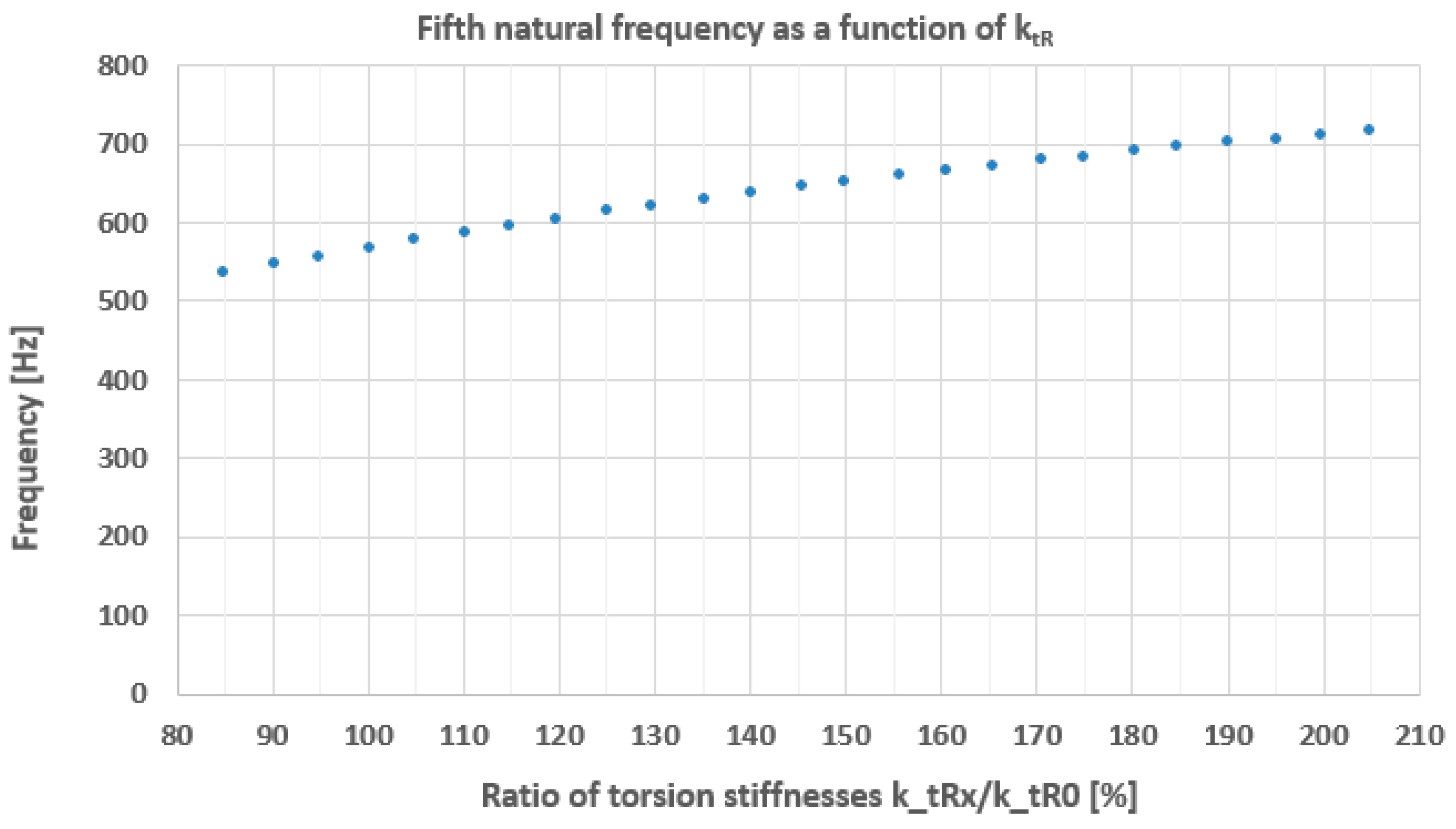
Figure 16.
Driving torque of the pinion for increased torsion stiffness ktR up to 205%.

Figure 17.
Magnitudes of harmonics as a function of the torsion stiffness ktR—the resonance state of the fifth eigenfrequency.
Figure 17.
Magnitudes of harmonics as a function of the torsion stiffness ktR—the resonance state of the fifth eigenfrequency.

Figure 18.
Time course of wheelset torsion amplitudes. Oscillations are performed via high pass filter.
Figure 18.
Time course of wheelset torsion amplitudes. Oscillations are performed via high pass filter.

Figure 19.
Time course of control current in the motor during torsional oscillations. The decreasing curve corresponds to the reduction in torque. Filtered oscillations are performed via high pass filter.
Figure 19.
Time course of control current in the motor during torsional oscillations. The decreasing curve corresponds to the reduction in torque. Filtered oscillations are performed via high pass filter.

Figure 20.
Power spectral density of simultaneous oscillation of wheelset and control current i1q.
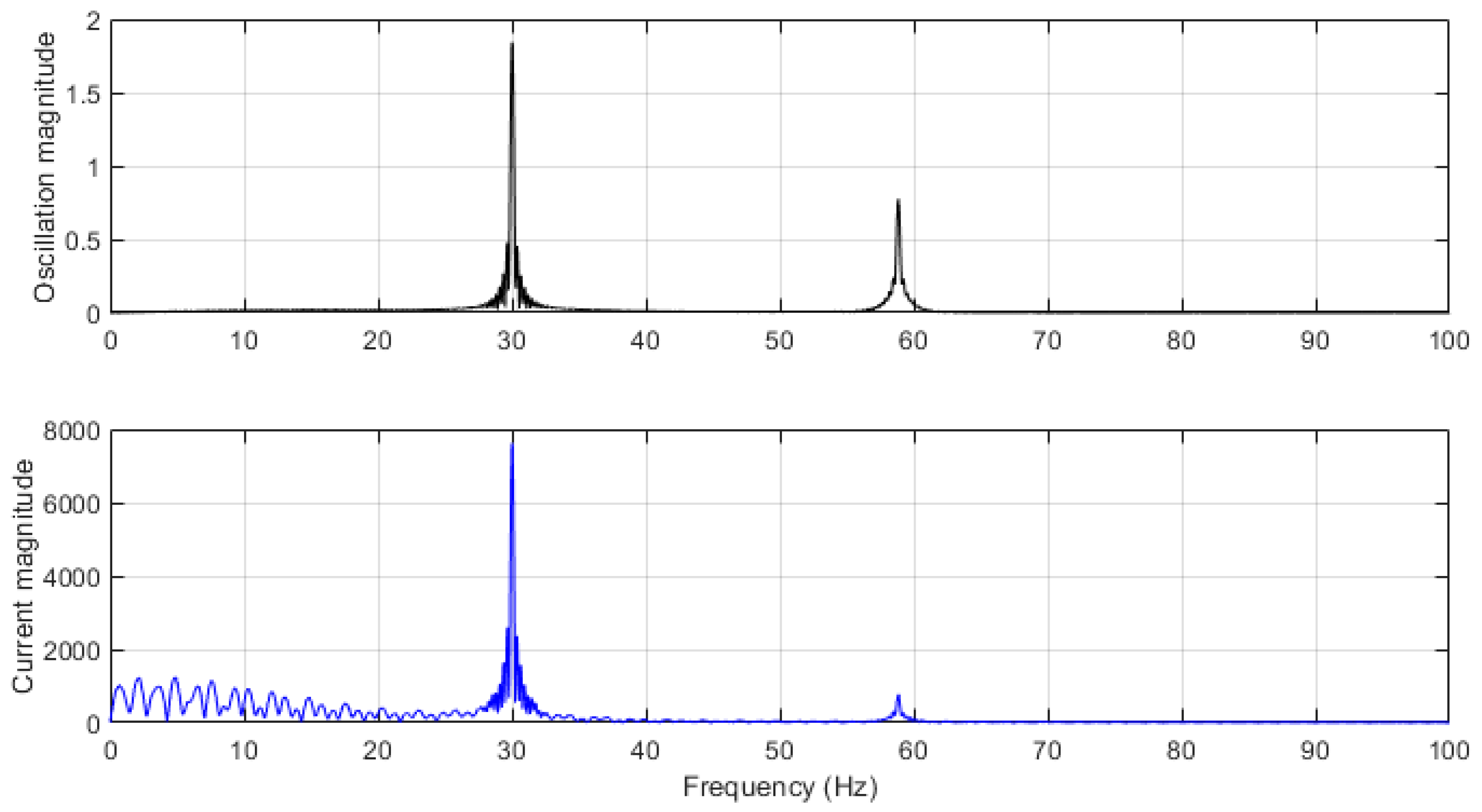
Figure 21.
Relation between amplitudes of oscillations of the axle and currents for the partially and fully suspended drive with relation to slip of a particular wheel [31].
Figure 21.
Relation between amplitudes of oscillations of the axle and currents for the partially and fully suspended drive with relation to slip of a particular wheel [31].

Figure 22.
Comparison of different time courses—standard torque control and the improved torque control that assumes currents in the motor.
Figure 22.
Comparison of different time courses—standard torque control and the improved torque control that assumes currents in the motor.

Disclaimer/Publisher’s Note: The statements, opinions and data contained in all publications are solely those of the individual author(s) and contributor(s) and not of MDPI and/or the editor(s). MDPI and/or the editor(s) disclaim responsibility for any injury to people or property resulting from any ideas, methods, instructions or products referred to in the content. |
© 2024 by the authors. Licensee MDPI, Basel, Switzerland. This article is an open access article distributed under the terms and conditions of the Creative Commons Attribution (CC BY) license (https://creativecommons.org/licenses/by/4.0/).
Share and Cite
MDPI and ACS Style
Dybala, V.; Fridrichovský, T.; Kalivoda, J. The Individual Drive of a Wheelset and the Problematics of Its Electromechanical Phenomena. Vehicles 2024, 6, 814-831. https://doi.org/10.3390/vehicles6020039
AMA Style
Dybala V, Fridrichovský T, Kalivoda J. The Individual Drive of a Wheelset and the Problematics of Its Electromechanical Phenomena. Vehicles. 2024; 6(2):814-831. https://doi.org/10.3390/vehicles6020039
Chicago/Turabian StyleDybala, Vojtěch, Tomáš Fridrichovský, and Jan Kalivoda. 2024. "The Individual Drive of a Wheelset and the Problematics of Its Electromechanical Phenomena" Vehicles 6, no. 2: 814-831. https://doi.org/10.3390/vehicles6020039