Article

Utilizing the Exergy Concept to Address Environmental Challenges of Electric Systems

1
Faculty of Electrical Engineering, University of Craiova, Decebal Street 107, Craiova, 200440, Romania
2
Faculty of Engineering and Applied Science, University of Ontario Institute of Technology, Oshawa, Ontario, ON, L1H 7K4, Canada
3
Military Institutes of University Education, Hellenic Naval Academy, Piraeus, 18539, Greece
4
University of Medicine and Pharmacy of Craiova, Craiova, 200349, Romania
*
Author to whom correspondence should be addressed.
Entropy 2012, 14(10), 1894-1914; https://doi.org/10.3390/e14101894
Submission received: 29 August 2012 / Revised: 20 September 2012 / Accepted: 27 September 2012 / Published: 11 October 2012
(This article belongs to the Special Issue Exergy: Analysis and Applications)

Abstract

:
Theoretically, the concepts of energy, entropy, exergy and embodied energy are founded in the fields of thermodynamics and physics. Yet, over decades these concepts have been applied in numerous fields of science and engineering, playing a key role in the analysis of processes, systems and devices in which energy transfers and energy transformations occur. The research reported here aims to demonstrate, in terms of sustainability, the usefulness of the embodied energy and exergy concepts for analyzing electric devices which convert energy, particularly the electromagnet. This study relies on a dualist view, incorporating technical and environmental dimensions. The information provided by energy assessments is shown to be less useful than that provided by exergy and prone to be misleading. The electromagnet force and torque (representing the driving force of output exergy), accepted as both environmental and technical quantities, are expressed as a function of the electric current and the magnetic field, supporting the view of the necessity of discerning interrelations between science and the environment. This research suggests that a useful step in assessing the viability of electric devices in concert with ecological systems might be to view the magnetic flux density B and the electric current intensity I as environmental parameters. In line with this idea the study encompasses an overview of potential human health risks and effects of extremely low frequency electromagnetic fields (ELF EMFs) caused by the operation of electric systems. It is concluded that exergy has a significant role to play in evaluating and increasing the efficiencies of electrical technologies and systems. This article also aims to demonstrate the need for joint efforts by researchers in electric and environmental engineering, and in medicine and health fields, for enhancing knowledge of the impacts of environmental ELF EMFs on humans and other life forms.

1. Introduction

Due to their multidisciplinary traits, the basic concepts of energy, entropy, exergy and embodied energy, which are founded in the field of physics, have been shown to have environmental, health, technical and economic significance as well. Many feel that these concepts can be explained, interpreted and applied in a more universal manner [1,2,3].
A sustainable industrial metabolism, integrating technical and ecological aspects, is one of the greatest challenges of humanity within the present industrial world [4,5,6,7]. Although science has not unified technical and ecological viewpoints, a set of conditions for the performance of sustainable electrical systems should be formulated. Starting from the observation that the ordered structures and life forms in nature are only one component in the complex web of the ecological interactions, we observe that people are a part of the evolutionary process of nature. The focus of this paper is to enhance understanding that human activities cannot be separated from the functioning of the entire system.
Energy occurs in many forms, which can be converted from one form to another [1]. According to the First Law of Thermodynamics, energy cannot be generated or destroyed. That means the quantities of energy involved in a process are conserved regardless of the feasibility of the process. Energy and matter flow through a system [6]. The motive force of the flow of energy or matter through a system is the contrast, or the gradient, or the level of order. The quality of the energy or matter constantly deteriorates in the flow passing through the system. The Second Law of Thermodynamics establishes the difference in quality of energy during a conversion process. It states that in any energy transfer or conversion process within a closed system, the total entropy after is greater than that before [1,3]. Moreover, even in open systems, the net change in entropy is positive. If the combination of the system and its surroundings is considered, the overall net effect is always to increase entropy, emphasized as level of disorder. More generally, processes in the universe can occur only in the direction of increased overall entropy or disorder. This implies that the entire universe is becoming more chaotic every day [1].
The concept of entropy, or conversely negentropy, which is akin to exergy, is a measure of the level of order [1,3,6], so exergy is the physical concept of a contrast or gradient, which quantifies its potential to cause action. A system in complete equilibrium with itself and the environment does not have any exergy, meaning it lacks the potential to cause action. In physics, work is a specific form of action, and exergy could be defined as work, i.e., ordered motion, or ability to perform work [1,2,3,6]. If there is no exergy destruction, which is not possible for real processes, there will be no action and everything will remain the same forever. While energy is a measure of quantity only, exergy is a measure of quantity and quality or usefulness [1,2,3,4,5,6,7,8,9,10,11,12,13,14,15,16,17,18,19,20].
Energy analysis is the traditional method of assessing the way energy is used in the operation of a system involving processing of materials and the transfer and/or conversion of energy. This usually entails performing energy balances, which are based on the First Law of Thermodynamics, and evaluating energy efficiencies. This balance is employed to determine and reduce waste energy emissions like heat losses and sometimes to enhance waste and heat recovery. However, an energy balance provides no information on the degradation of energy and resources during a process and does not quantify the usefulness of the various energy and material streams flowing through a system and existing as products and wastes [1,2,8,15,16,19].
Exergy analysis overcomes the limitations of the First Law of Thermodynamics. The concept of exergy is based on both the First and Second laws [1,13,14,17,18,20]. Exergy is evaluated relative to a reference environment, which is assumed to be infinite, in equilibrium, and to enclose all other systems. Exergy can be seen as the carrier of the energy quality and, since an exergy balance demonstrates that exergy can be destroyed, the exergy efficiency reflects the useful part of the energy interactions [1,17,20]. When energy loses its quality, exergy is destroyed, and exergy is the part of energy which is useful. Consequently, exergy analysis clearly identifies the locations of energy degradations in a process, knowledge which can lead to improved operation or technology [1,2,3,4,5,6,7,8,9,10,11,12,13,14,15,16,17,18,19,20]. Also, exergy analysis reveals whether or not and by how much it is possible to design more efficient systems by reducing the inefficiencies in existing systems. Exergy assessment is also a tool for addressing the impact on the environment of energy and other resource utilization, and reducing or mitigating that impact, thereby identifying whether an industrial system contributes to achieving sustainable development or is unsustainable [1,13,14,17,18,20].
Industrial ecology is an emerging framework within the sustainable development field [21,22,23,24,25]. The concepts, tools and goals of industrial ecology need to be addressed along with the understanding that sustainable development is not about certificates or licenses but instead is about the vitality of life on Earth. Future needs for sustainable development are likely to include a change in human values through education, and an industrial metabolism shift through responsible practical actions. Based on the conviction that nature has generated life, industrial ecology seeks for a new approach to industrial systems, viewed not in isolation from natural surroundings but in concert with them. Within the framework of industrial ecology, an approach to anthropogenic systems and ecological systems as parts of the same system, could provide a holistic view of the interactions and symbiotic interrelationships among human activities, industrial practices and ecological processes [21,22,23,24,25,26,27].
This article describes their applicability of exergy and exergy methods to electrical devices from technical and environmental perspectives. The electromagnet system is used as an example to illustrate the use of exergy as a tool to understand and improve efficiency. The objective is to understand better exergy efficiencies and losses for electrical systems, thereby assisting efforts to improve them and make them more sustainable, both technically and environmentally.

2. Dual View of Electromagnet System

Many feel that exergy is applicable only to systems or studies involving thermodynamics, in areas like mechanical and chemical engineering. Consequently, the full value of exergy is not achieved because it is neglected or underutilized in other fields. One such area is electrical engineering, where exergy applications are uncommon [10,33].
We highlighted previously that sustainability concepts can be applied in a simple way within the framework of industrial ecology, and that such an approach provides an alternate view of systems and equipment which convert energy and materials, related both to technical and environmental systems [10,31,32,33]. In line with this idea, one of most convincing example of the usefulness of the embodied energy and exergy concepts for analyzing systems which convert energy is an electromagnet system.
Many examples can demonstrate how exergy methods improve understanding of efficiencies and help increase them. An overview of the operation of electromagnets is presented in this article. The electromagnet is not only an element of many control and protection electrical devices (e.g., the motor element in electromagnetic contactors, relays, circuit-breakers and switchers), but also a small-scale system. In the dualist view taken here, the electromagnet system is taken to be surrounded by two environments: technical and ecological. Within the technical surroundings, the electromagnet system is closed, whereas within the ecological environment the electromagnet is seen as an open system. The gradient relative to the reference frame surrounding the electromagnet is observed as different from the structure of the device and its reference environment. This consideration implies that the “energy loss” is only a correct notion only taking into account the technical reference frame. For the ecological reference frame, more appropriate terms are “exergy losses”.
In line with these concepts, it is useful to determine analogies between ecosystems and electrical systems regarding the key features of structure and function. One significant feature is that the changes in ecosystems are not continuous. A second feature emphasizes that the changes, seen as ecological loops, have temporal scales varying from slow accumulation to abrupt releases. The latter can occur at specific times or at locations of increased vulnerability. In this article, starting from these assumptions, we approach with a dual view three essential aspects of electromagnet theory: (1) assessing the energy embodied in the field of a electromagnet without elements in motion (i.e., an electromagnet with an immobile armature) and evaluating on this basis the static and dynamic inductances of the circuit, (2) exergy analysis on the basis of the useful mechanical work developed by the magnetic field forces when the electromagnet armature is in motion, and (3) assessing the electromagnet force and torque, as motive force of output exergy.

2.1. Energy and Exergy Balances

An industrial ecosystem does not have a single equilibrium point. Rather, the system moves among multiple stable states. The transient regime of an electromagnet supplied by a constant voltage source represents a system movement between two equilibrium points [10]. We consider an electromagnet with a ferromagnetic core and an immobile armature [10,28,29,30]. The excitation coil (made from copper) with w turns has an electric resistance r (in Ω). When the excitation winding is connected to a constant voltage source U = ct. (at time t = 0), a current i appears, which increases from a value of 0 (the first stable state of this industrial ecosystem) to the steady-state regime value Is = U/r (the second stable state), following the curve shown in Figure 1.
Figure 1. Evolution in transient regime of the electromagnet winding current when the ferromagnetic core is fixed.
Entropy 14 01894 g001
In the current diagram in Figure 1 i = i(t), and the quantity τ = L / r represents the delay time electric constant of the circuit. Normally, the current i reaches the steady-state value Is after 4τ to 5τ. From the technical viewpoint, all electromagnetic processes of the circuit during the transient regime are governed by the Electromagnetic Induction Law. Consequently, the following equations are obtained:
- U + r i = e e = - d ψ d t ψ = w
We can write U = ri + /dt, which indicates that the applied voltage to the electromagnet winding terminals is balanced in the transient regime by the voltage drop ri on the coil resistance and by the electromotive back force –e = /dt induced in the coil. The latter is caused by the total flux variation Ψ = , where Φ denotes the fascicular flux.
With these expressions, the energy balance of the electromagnet can be obtained during the transient regime within the technical reference frame:
0 t U i d t = 0 t r i 2 d t + 0 ψ i d ψ
or:
W = W J + W m
where W = 0 t U i d t represents the electric energy provided by the supply source, W J = 0 t r i 2 d t represents energy losses by the Joule effect, and W m = 0 ψ i d ψ is the energy embedded in the magnetic field.
We establish subsequently the exergy balance for the same transient regime, noting that exergy is a measure of the potential of a system or flow to cause change as a consequence of not being completely in stable equilibrium relative to a reference environment. Unlike energy, exergy is not subject to a conservation law (except for ideal, or reversible, processes). Rather exergy is consumed or destroyed, due to irreversibilities in any real process. Within the ecological reference frame it is instructive not to refer to energy losses, but rather to express energy flows and exergy losses. The exergy balance within the ecological reference frame can be written on the basis of the input-output method as:
X = X J + Δ X m
where X represents the input exergy, XJ the destroyed exergy (by the Joule effect) and ΔXm the embedded exergy (or embodied or stored energy) in the magnetic field of the electromagnet. Consequently, the magnetic field exergy can be obtained from the input exergy after the exergy losses in the coil are determined.
After the transient regime, the winding current reaches the steady-state value Is = U/r and the magnetic flux attains a constant value corresponding to the stable regime Ψ = ct. This regime begins at the time when = 0 and the electromagnet system reaches a new equilibrium point. In this stable state the energy embedded in the magnetic field remains constant and all the energy from the source W offsets coil conductor exergy losses XJ.
The destruction of exergy during the transient process between two equilibrium points is not caused only by the electromagnetic coil. Since the total magnetic flux (of the winding with w turns) Ψ = depends on the fascicular magnetic flux Φ = BS and because the induction curve B = f(H), corresponding to the iron core magnetizing characteristic, which is non-linear, the resulting total flux Ψ depends on the current, i.e., Ψ = f(i). The corresponding a curve is represented in Figure 2. The linear dependence indicated at position (a), corresponding to the straight line Ψ = Li with L = ct, corresponds to the excitation coil without a ferromagnetic core (coil on the air).
Figure 2. Electromagnet characteristic ψ = f(i): (a) coil in the air; (b) coil on the ferromagnetic core in transient regime of the electromagnet winding current when the ferromagnetic core is fixed.
Entropy 14 01894 g002
Also, the non-linear curve Ψ = f(i) shown at position (b) corresponds to the winding on a ferromagnetic core. The shape of curve (b) reflects the non-linearity of the iron core magnetizing characteristic and depends both on the dimensions and type of the core material, and on the total magnitude of the electromagnet air gap.
Corresponding to the non-linear curve Ψ = f(i) at position (b), the magnetic field embodied energy ΔXm (in the case of a constant air gap) corresponds to the hatched surface in Figure 2. That is:
Δ X m 1 = 0 X 1 i d ψ = s u r f a c e ( 0 1 ψ 1 )
For any point on the characteristic Ψ = f(i), the ratio between the total magnetic flux Ψ and the current i, which is positive, represents the static inductance Ls (see Figure 3):
L s = ψ ( i ) i > 0 L s = L s ( i ) = t g α
The static inductance Ls is variable and depends on the current i, as shown in Figure 4.
In the case of windings on a ferromagnetic core, we define the dynamic inductance Ld (see Figure 3) by the relations:
L d = d ψ d i | i = i 1 ; L d = L d ( i ) = t g β
Figure 3. Defining static inductance Ls and dynamic inductance Ld using the variation of total magnetic flux with current.
Entropy 14 01894 g003
For instance, if dL/dt = 0 (i.e., L is independent of time), the inductance necessary according to the Electromagnetic Induction Law is the dynamic inductance Ld:
e = - L d i d t L = - e d i d t = - ( - d ψ d t ) d i d t = d ψ d i = L d
Figure 4. Curves of static Ls = f1(i) and dynamic Ld = f2(i) inductances as a function of current.
Entropy 14 01894 g004
The dynamic inductance Ld is variable and depends on the current i (see Figure 4). During the transient process of the industrial ecosystem movement among multiple stable states, therefore, we must work with the dynamic inductance rather than the static inductance (Figure 4), taking into account all further technical consequences.

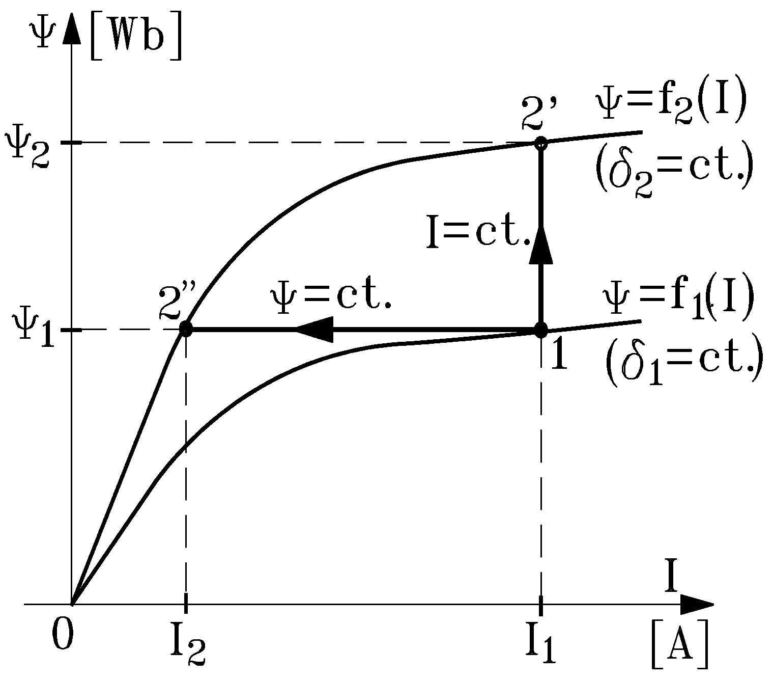
2.2. Useful Mechanical Work of Armature in Movement

Since energy is often thought of as motion and exergy as work [10,20,31,32], the electromagnetic force or torque developed by an electrical ecosystem can be interpreted, regardless of the reference frame considered, as the driving force of useful work, i.e., the ecosystem output exergy. In line with this idea we will determine the mechanical work W12 caused by the magnetic field forces of the electromagnet system.
For any electromagnet with embedded energy in the ferromagnetic core, the electromagnetic forces draw the armature to the core and reduce the air gap as a result. In the evaluation of the mechanical work W12 caused by the magnetic field forces (when the armature is in movement), we consider an electromagnet characterized at the initial equilibrium point by the air gap magnitude δ1 and the flux curve Ψ = f1(I) on which, in the first stable regime, the operation has been stabilized at point 1, with the coordinates I1 and Ψ1 (see Figure 5a).
Figure 5. Characterization of initial (a) and final (b) stable states of the electromagnet with the armature in motion.
Entropy 14 01894 g005
After the armature attraction, the final stable state is described by the air gap δ2 (with δ2 < δ1) and by the flux characteristic Ψ = f2(I), on which is found the second equilibrium point (point 2), with coordinates I2 and Ψ2 (Figure 5b).
With Equation (4), the energy embedded in the magnetic field in the initial state Wm1 and the final state Wm2 is proportional to the hatched surfaces in Figure 5. That is,
W m 1 = 0 ψ 1 i d ψ = s u r f a c e ( 0 1 ψ 1 )
W m 2 = 0 ψ 2 i d ψ = s u r f a c e ( 0 2 ψ 2 )
Moreover, it is assumed that the evolution from initial state 1 to final state 2 occurs slowly, according to the ecosystem exergy accumulation in the loop, so that all intermediary states are stationary.
Therefore, in the frame (I, Ψ), all intermediary balance points are on the curve Ψ = Ψ(I), between points 1 and 2, as illustrated in Figure 6.
Figure 6. Evolution curve ψ = ψ(I) and the change in magnetic energy ΔWm when the armature moves.
Entropy 14 01894 g006
In these conditions, during the armature movement (from δ1 to δ2), a dual energy change occurs between the source and the magnetic field. First, the source provides to the electromagnet the change in energy ΔWm, proportional to the hatched surface corresponding to the flux variation from Ψ1 to Ψ2 on the evolution curve Ψ(I) in Figure 6:
Δ W m = ψ 1 ψ 2 i d ψ = s u r f a c e ( ψ 1 1 2 ψ 2 )
Second, the magnetic field forces perform mechanical work W12, corresponding to the displacement Δδ of the electromagnet armature.
Consequently, in the absence of the dissipative magnetic forces, the energy balance of the electromagnet in the technical reference frame, under the varying conditions of the state-quantities due to the armature movement, is described by the following equation:
W m 1 + Δ W m = W m 2 + W 1 2
Within the reference frame of industrial ecology, it is helpful to write the exergy balance for the previous situation on the basis of input-output analysis:
X i n + Δ X s y s X o u t X d e s = 0
where Xin is the input exergy, corresponding to the magnetic field embodied energy in the initial stable state; ΔXsys is the change in exergy of the system during the transient process; Xout represents the output exergy (including both the magnetic field embodied energy in the final stable state and the net exergy transfer by useful mechanical work); and Xdes is the exergy destruction by the dissipative magnetic forces of the system.
Neglecting the exergy destroyed by dissipative forces, the meanings of Equations (11) and (12) are similar, but they are expressed in technical and ecological terms, respectively. The use of exergy, as noted earlier, provides insights into environmental and ecological impact.
The mechanical work performed, which can be expressed as W 1 2 = W m 1 + Δ W m - W m 2 , can be illustrated graphically with Equations (9) and (10):
W 1 2 = s u r f a c e ( 0 1 ψ 1 ) + s u r f a c e ( ψ 1 1 2 ψ 2 ) - s u r f a c e ( 0 2 ψ 2 ) = s u r f a c e ( 0 1 2 )
The mechanical work W12 performed by the magnetic field forces when the electromagnet armature is in motion is equal to the surface (012) in Figure 7, bounded by the curves Ψ = f1(I), Ψ = f2(I) and by the evolution curve Ψ = Ψ(I). The area (012) is represented by the hatched surface in Figure 7.
Figure 7. Mechanical work W12 at armature movement.
Entropy 14 01894 g007
In the coordinates frame (IOΨ), the most simple evolution curves Ψ(I) from stable state 1 to stable state 2 are parallel straight lines with the axes (see Figure 8):
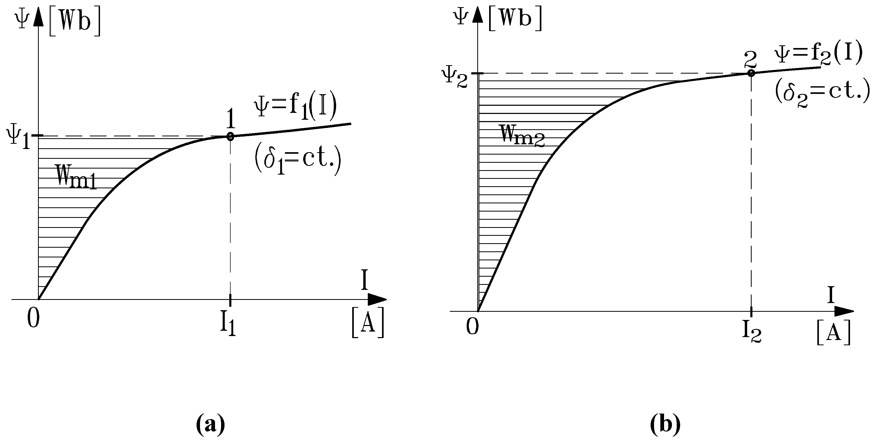
  • at a constant current I = I1 = const., when the evolution is described by the straight line 1 2 ¯ or
  • at a constant flux Ψ = Ψ1 = const., when the evolution follows the straight line 1 2 ¯ .
Figure 8. Two particular evolutions ψ = ψ(I): 1-2' (at I = const.) and 1-2" (at ψ = const.).
Entropy 14 01894 g008
In such cases, the mechanical work W12, on the basis of the graphical interpretation described earlier, can be approximated with the following relations:
a)
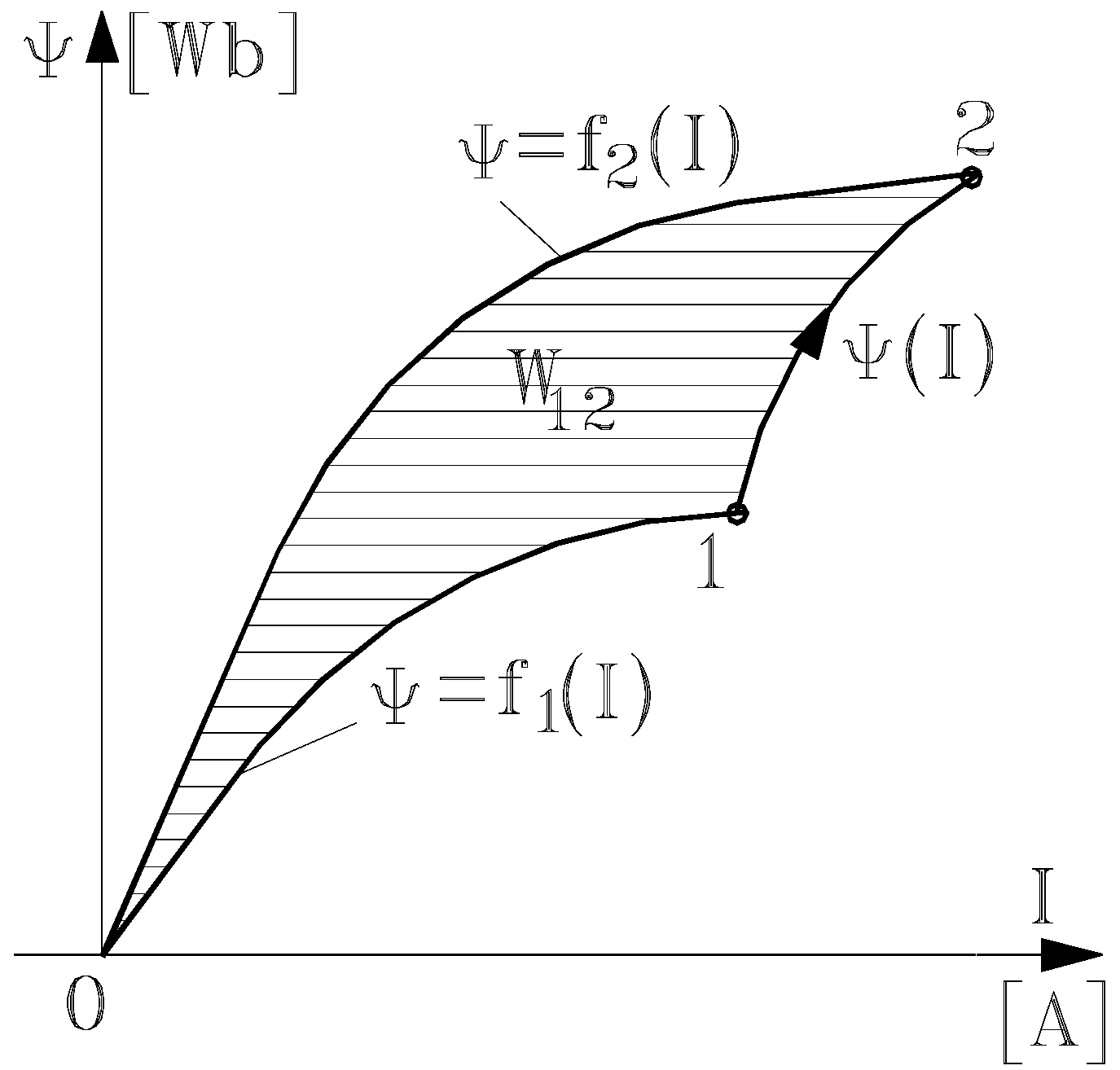
W12 = W12' at I = const. (when the evolution is along the straight line 1 2 ¯ ), where
W 1 2 = s u r f a c e ( 0 1 2 ) 1 2 ( ψ 2 - ψ 1 ) I 1 = 1 2 Δ ψ 1 2 I 1
b)
W12 = W12" at Ψ = const. (when the evolution is along the straight line 1 2 ¯ ), where
W 1 2 = s u r f a c e ( 0 1 2 ) 1 2 ψ 1 ( I 1 - I 2 ) = - 1 2 ψ 1 ( I 2 - I 1 ) = - 1 2 ψ 1 Δ I 1 2
Several points are highlighted in the analysis reported to this point:
(1)
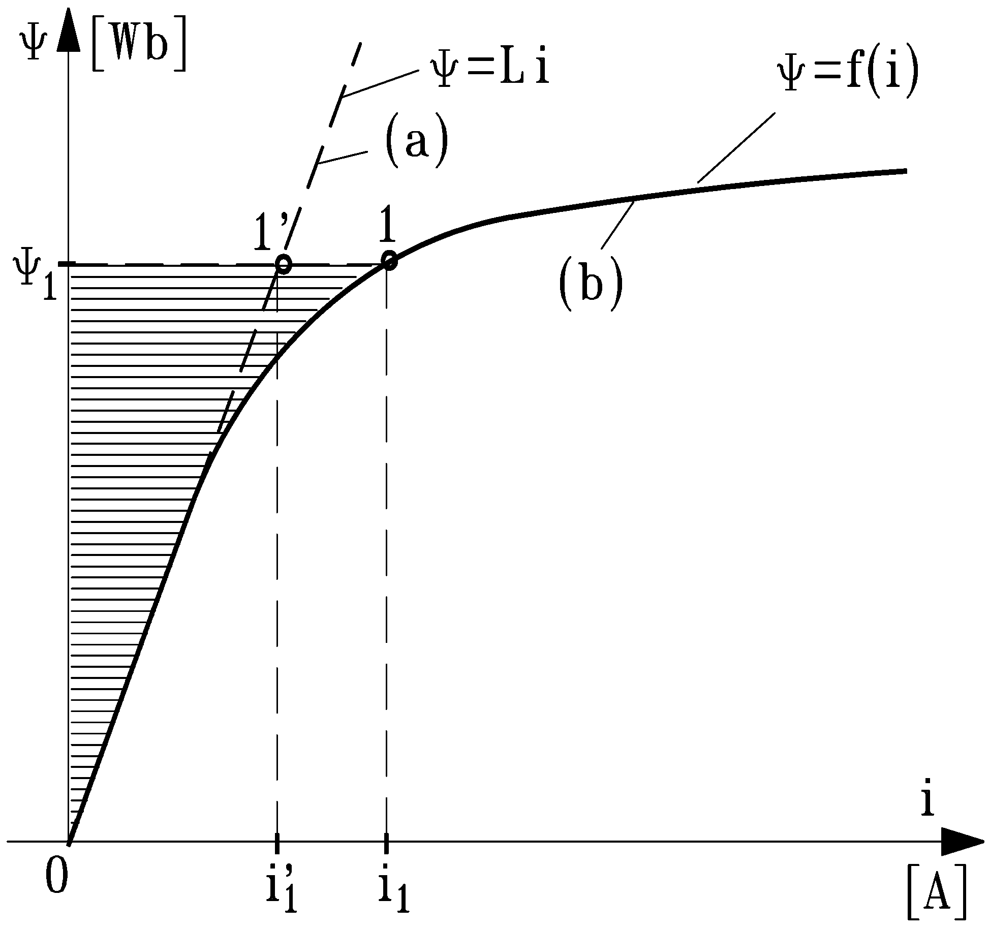
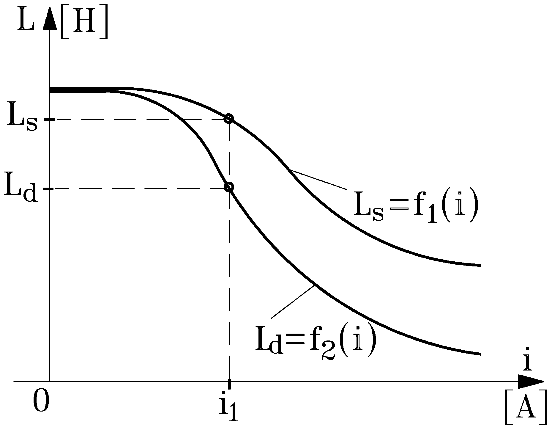
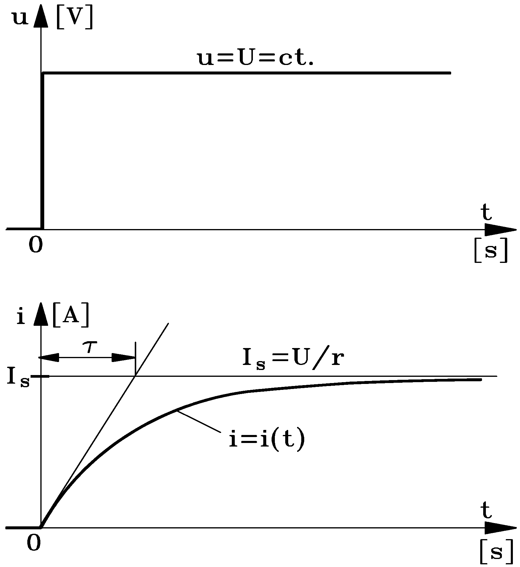
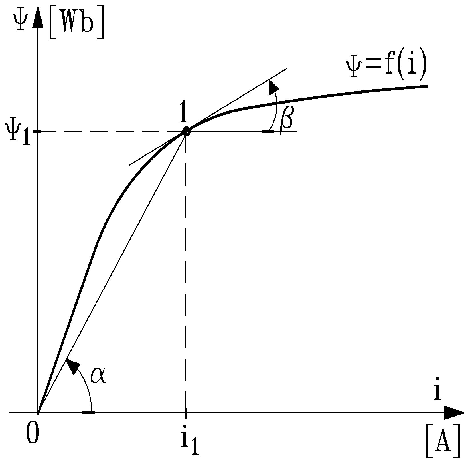
Due to the existence of two inductances (static Ls and dynamic Ld), the “risk” of the double interpretation appears often. Only if the coils do not have a ferromagnetic core (when Ψ = f(i) is a straight line) are the two inductances (static and dynamic) the same, i.e., Ls = Ld = L and Ψ = L i This result implies that, during the transient process of the industrial ecosystem moving among multiple stable states, it is advantageous to work with the dynamic inductance rather than the static inductance.
(2)
Graphical interpretations have been obtained theoretically of the classical formulas for the calculation of mechanical work, both at constant current (I = const.) and at constant flux (Ψ = const).
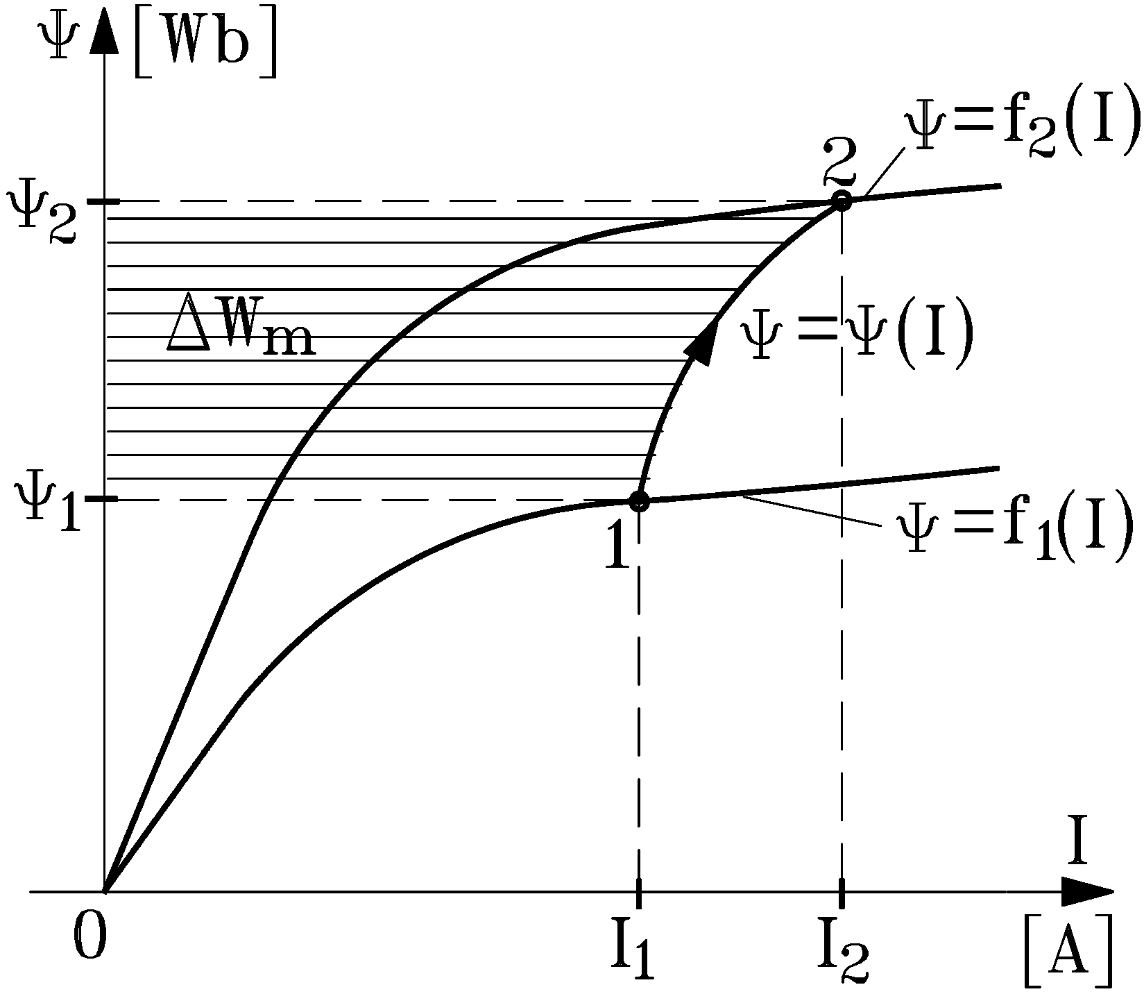
(3)
With the general expression W m = 1 2 I ψ for the embedded magnetic energy, the mechanical work expressions W12' from Equation (14) and W12" from Equation (15) (performed for the armature in motion) can be written in a unitary mode with the following expressions:
W 1 2 = Δ W m 1 2 | I = c t .     ;     W 1 2 = - Δ W m 1 2 | ψ = c t .

2.3. Electromagnet Force and Torque

When the electromagnet armature undergoes a displacement Δ δ (from steady-state position δ 1 to steady-state position δ 2 < δ 1 ), the attraction force determines the mechanical work W12. The corresponding embedded magnetic energy variation is Δ W m 1 2 = W m 2 W m 1 . The relations in (16) apply between the performed mechanical work W12 and the magnetic energy variation Δ W m 1 2 .
Moreover, the elementary mechanical work d W for elementary displacements d δ or d α of the electromagnet armature over small distances is determined with the following formulas:
d W = F d δ
d W = M d α
Here, d α denotes the armature rotation angle when the air-gap is modified linearly by d δ (determined by the action of the force F and the torque M , respectively). Corresponding to the elementary displacements, the relations (16) can be rewritten as
d W = d W m | I = c t .
d W = d W m | ψ = c t .
The following formulas result as a consequence of (17) and (18):
a) for the force:
F = d W m d δ | I = c t .     or     F = - d W m d δ | ψ = c t .
b) for the torque:
M = d W m d α | I = c t .     or     M = - d W m d α | ψ = c t .
These results are general and identical with those determined via electrotechnics with the method of Generalized Forces in Magnetic Field. But, these formulas should also be interpreted within the framework of industrial ecology. Since exergy is the physical concept of contrast or gradient, which quantifies its potential for action, and work is a specific form of action, it means that exergy could be defined as work, i.e., ordered motion. This insight supports the idea that the magnetic force F or the torque M developed by the electromagnet, regardless of the reference frame considered (technical or ecological), can be interpreted as the driving force of the mechanical work, i.e., the electromagnet output exergy [10,31,32,33]. These issues are now further discussed.

2.3.1. Electromagnet Operation with Constant Current-turns

In the case of d.c. electromagnets, the absorbed current I does not vary with the armature displacement. Consequently, when I = c o n s t . (and the current turns θ = w I = c o n s t . ) and taking into account that ψ = L I , the magnetic energy expression becomes W m = 1 2 L I 2 , where L denotes the static inductance L s . The magnetic energy varies with the armature displacement. Thus, at θ = w I = c o n s t . (i.e., I = c o n s t . ), the force F and the torque M can be written as follows:
F = d W m d δ | I = c t . = 1 2 I 2 d L d δ     ;     M = d W m d α | I = c t . = 1 2 I 2 d L d α
Since the inductance L = w 2 / R m depends on the total magnetic resistance (reluctance) R m of the electromagnet magnetic circuit, it is useful to highlight the two components of R m : R m F e which denotes the reluctance associated with the iron part of the electromagnet and R m δ which denotes the reluctance of the electromagnet air gaps. Since R m δ « R m F e :
R m = R m F e + R m δ R m δ
as a result:
L = w 2 R m w 2 R m δ = w 2 Λ δ
Consequently, the expressions (21) can be rewritten in the following simplified forms:
F 1 2 θ 2 d Λ δ d δ     ;     M 1 2 θ 2 d Λ δ d α
Here, Λ δ = 1 / R m δ denotes the permeance of the air gaps.

2.3.2. Electromagnet Operation with Constant Magnetic Flux

To assess the case of electromagnet operation with a constant magnetic flux, we consider a.c. electromagnets. When a magnetizing winding having electric resistance R is supplied from a sinusoidal voltage source with a r.m.s. value U = c o n s t . and frequency f = c o n s t . , in a steady-state sinusoidal regime between the r.m.s. voltage U and the r.m.s. current I, we can write:
U = ( R I ) 2 + ( ω ψ 2 ) 2
Assuming the voltage drop on the resistance R I can be neglected (at U = c o n s t . and ω = 2 π f = c o n s t . , with U » R I ), relation (25) expresses the condition of the electromagnet operation at constant flux:
U ω ψ 2 ψ = 2 U ω = c o n s t .
When ψ = c o n s t . , d ψ / d δ = 0 and the force F and the torque M can be determined as follows:
F = - d W m d δ | ψ = c t . = - 1 2 ψ d I d δ
M = - d W m d α | ψ = c t . = - 1 2 ψ d I d α
Since I = ψ L , the current derivative at ψ = c o n s t . is:
d I d δ = - ψ L 2 d L d δ     ;      d I d α = - ψ L 2 d L d α
Substitution of the expressions (28) into the earlier relations (27) leads to the expressions in (21).

2.3.3. Discussion of Forces

The total force developed by an electromagnet can be determined as the sum of the attraction forces F δ i corresponding to all electromagnet active air gaps:
F = i = 1 k F δ i
The attraction force in an air gap F δ i can be determined by applying the formula for Maxwell tensions in a uniform magnetic field:
F δ i = T n i S δ i = w m i S δ i = B δ i 2 2 μ 0 S δ i = 1 2 μ 0 i 2 S δ i
Here, T n i = B δ i H δ i 2 = B δ i 2 2 μ 0 = w m i is the Maxwell tensor in the air-gap i; w m i represents the magnetic energy density in the considered air gap; B δ i represents the magnetic field in the air gap; S δ i is the equivalent cross section of the air gap; μ 0 = 4 π 1 0 7 [ H / m ] is the permeability of free space; and i = B δ i S δ i is the magnetic flux through the air gap considered.
This result can be applied in the case of air gaps with a magnetic field that is uniformly distributed at all points of the cross-section ( B δ = c o n s t . ). If the magnetic field in the air gap is not constant, then the cross-section area S δ is divided into elementary parts Δ S δ k , where the magnetic field B δ can be considered constant, i.e., B δ k = c o n s t . Consequently, for each air gap, the attraction force is determined as the sum of the elementary forces Δ F δ k = B δ k 2 Δ S δ k / ( 2 μ 0 ) corresponding to the individual attractions of each elementary section.

3. Discussion of Electromagnetic Quantities as Environmental Parameters

The outcomes of the previous section shed light also on an analogy observed between a technical system and an ecosystem. People have used laws of Nature in engineering applications, and concepts, characteristics and features associated with natural phenomena are utilized in engineering applications in what we refer to here as technical regimes. In addition, we need to consider that many quantities and parameters in the field of electromagnetism also have significance relative to the ecological surroundings.
Shedding light on the ecosystem model, the electromagnet device as an industrial ecosystem can perform mechanical work with a magnitude that depends on electric current and magnetic flux. These last two quantities are examined further in relation to the environmental perspective of this article.
Although electric current and magnetic flux are technical quantities defined within electromagnetism theory, they have environmental relations and as such arguably may be viewed as environmental parameters, since we live in a world in which no biological ecosystem is free of human influence [4,13,15,17,20,33]. The fundamental laws of electricity and magnetism are well understood, but we must enhance the way of thinking that they should allow a large variety of possible interactions with the complex, inhomogeneous biological environment and continuously varying natural ecosystems, particularly human beings and living organisms [27].
Usually, we characterize the environment through such classical parameters as its temperature, pressure, volume, humidity, etc. In recent decades, numerous studies have been reported that suggest we also need to consider electromagnetic waves as environment quantities. For instance, a study [34] performed in 2002 by Spectrum Management assessed the electromagnetic field intensity in the city of Toronto, Canada. In the investigation, electromagnetic field intensity levels were measured within the frequency range 150 kHz to 3 GHz at selected locations. The results emphasize that human activities, such as maritime and aeronautical services, television broadcast, wireless cable TV and cellular and paging services, are increasing the environmental impacts caused by electromagnetic field intensity levels. Also, we know that radioactive materials, both natural and anthropogenic (e.g., materials artificially created by people during nuclear activities) can emit gamma rays. Electromagnetic waves exist not only because of human activities, but also due to natural sources in the universe. For example, the sun is a source of ultraviolet (UV) radiation, and the full moon and stars, and other “hot” objects in space emit UV electromagnetic waves. Radio, UV and gamma rays and all other parts of the electromagnetic spectrum are fundamentally part of the electromagnetic field. The electromagnetic spectrum is usually expressed in terms of energy, wavelength or frequency, but we need to understand more about the environmental features of electromagnetic field quantities.
This enhanced understanding may be achievable, since there is no reason to believe that different types of electromagnetic interaction do not exist in the complex biological environments on Earth. Further, in line with the idea that electrical power is used all over the World, and everyday civilization can be interpreted in correlation with use of electricity, we should build awareness on concerns and questions raised regarding whether exposure to extremely low frequency (ELF) electromagnetic fields (EMFs) could produce adverse health consequences [35,36,37,38,39,40,41,42,43,44,45,46,47,48,49,50,51,52,53,54,55]. Both electric and magnetic fields exist close to the overhead power lines and power transformers and surrounding the electric devices, and awareness of impacts on human health and other life forms should be built, since it is globally accepted [35,36,37,38,39,40,41,42,43,44,45,46,47,48,49,50,51,52,53,54,55] that ELF EMFs can induce electric fields and currents in a human or an animal.
Many studies have been performed [35,36,37,38,39,40,41,42,43,44,45,46,47,48,49,50,51,52,53] in order to assess the short-term and potential long-term effects of exposure to ELF electromagnetic fields in the frequency range up to 100 kHz. Still, interpreting the results of epidemiological studies is very difficult, since people exposed to ELF EMFs live in very different environments and have different patterns of exposure. For a relevant interpretation of studies on potential harmful effects of exposure to ELF EMFs, there are necessary reliable data on ELF electromagnetic field exposure from case-controlled studies carried out in several countries, in similar conditions.
Reported findings [39,40,41,42,43] show that evidence of potential harmful effects on human health associated with ELF EMF exposure could be obtained from epidemiological studies along with experimental studies, the main concern being the incidence of cancer. It has been reported that children living around overhead power lines, power transformers and electric devices had an increased risk for developing cancer [39,42,43]. Despite much research, and despite the fact that laboratory studies have not provided convincing evidence for a causal relationship between increased childhood leukemia and electromagnetic field exposure, there still exists epidemiological research suggesting that chronic low intensity ELF EMF exposure is associated with an increased risk for childhood leukemia, when the average exposure exceeds 0.3 μT to 0.4 μT [39,43].
Apart from the childhood leukemia issue, there are other uncertainties regarding the health impact of ELF EMF. Some studies [44] conclude that there is no evidence for proving adverse health effects associated with exposure to electromagnetic fields at environmental levels, but some research [45,46,47] reveals health consequences of personnel exposed to ELF EMFs, concluding that, at very high exposure levels, the nervous system can be affected. This is a convincing hypothesis, demonstrating the electromagnetic field perception by humans and other life forms [48,49]. For instance, humans can perceive time-varying (AC) and static (DC) electric fields, since the central nervous system is a potential site of interaction between biological systems and electromagnetic fields, due to the electrical sensitivity of tissues [40,50]. Some studies [45,52] suggest that occupational exposure to ELF EMFs might have a detrimental effect on quantity and quality of night sleep. In line with same idea of occupational exposure to EMFs, extrapolation of laboratory data [46,52] in correlation with the results of clinical research conducted on the biological hypothesis suggests that chronic occupational exposure to ELF EMFs may affect specific types of cardiovascular disease by altering cardiac autonomic control. Furthermore, under this hypothesis, such exposures would be linked to increased risks for arrhythmia related deaths and deaths caused by acute myocardial infarctions.
All performed studies have strengths and weaknesses, and there remains debate over health effects resulting from exposure to ELF EMFs, since questions regarding the link between cancer and the production, distribution, and use of energy has not yet been clearly answered. Still, it is widely accepted that health risks associated with environmental impact are exhibited as biological effects accumulated over time and depending on dose of exposure to ELF EMFs [53]. For this reason, society should be aware of any adverse health effects, and worldwide there should be mandatory ELF EMF exposure guidelines, standards and directives.
Consequently, in 1996 the World Health Organization (WHO) established the International Electromagnetic Fields Project [54] to investigate potential health risks associated with technologies emitting EMFs, and in 2005 the Task Group of scientific experts of WHO concluded a review of the health impacts of ELF electric and magnetic fields.
Following publication of WHO Environmental Health Criteria Report on ELF fields, the International Commission on Non-Ionizing Radiation Protection established international guidelines for limiting high-level exposure to time varying electric, magnetic and electromagnetic fields [55].
The aim of these exposure guidelines, standards, recommendations and directives for ELF EMFs is to avoid situations in which electric fields and currents induced by external electromagnetic fields could create harmful health effects. In line with this discussion, a necessary further step might be to view the magnetic flux density and the electric current intensity as environmental parameters.

4. Conclusions

The benefits of using sustainability concepts to understand the efficiencies of systems and devices which use and convert electric energy and to guide improvement efforts have been demonstrated. It is concluded that the concepts encompassing exergy and embodied energy have a significant role to play in evaluating and increasing the efficiencies of such devices. Exergy should prove useful in such activities to engineers and scientists, as well as decision and policy makers.
We have demonstrated in this article that industrial ecology permits an alternate view of human applications, related both to technical and environmental systems. We shed light on the electromagnet torque as the motive force of the output exergy, and express the electromagnet force and torque as a function of the electric current and the magnetic field, supporting the view of the necessity of discerning interrelations between science and the environment.
Our knowledge of the Universe should be used in assessing the viability of electric devices in concert with ecological systems. A step might be to view the magnetic flux density and the electric current intensity as environmental parameters.
This study goes on to enhance the way of thinking that human activities cannot be separated from the entire system existence on Earth, since within the present industrial metabolism no biological ecosystem is free of human influence. The health risks and uncertainties, associated with environmental impact resulting from exposure to ELF EMFs, have not yet been clearly answered, yet society should nevertheless be aware of any adverse health effect, and worldwide there should be mandatory the ELF EMF exposure guidelines, standards and directives.
The results are expected to be useful for joint efforts by researchers in electric and environmental engineering, and in medicine field for enhancing knowledge of the impacts of environmental ELF EMF on humans and other life forms.

References

  1. Dincer, I.; Rosen, M.A. Exergy: Energy, Environment and Sustainable Development; Elsevier: Oxford, UK, 2007. [Google Scholar]
  2. Rosen, M.A. A concise review of energy-based economic methods. In Proceeding of 3rd IASME/WSEAS International Conference on Energy & Environment, Cambridge, UK, February 2008; pp. 136–142.
  3. Wall, G. Exergy Tools. In Proceeding of the Institution of Mechanical Engineers, Part A: J. Power and Energy, March 2003; pp. 125–136.
  4. Rosen, M.A.; Bulucea, C.A. Assessing electrical systems via exergy: a dualist view incorporating technical and environmental dimensions. In Proceeding of 6th WSEAS International Conference on Engineering Education, Rhodes, Greece, July 2009; pp. 116–123.
  5. Wall, G. Exergy, ecology and democracy: concepts of a vital society or a proposal for an exergy tax. In Presented at 2nd European Congress on Economics and Management of Energy in Industry, Estoril, Portugal, April 1994.
  6. Wall, G. Introduction to life support systems and sustainable development. available at: http://www.exergy.se/ftp/ilsssd.pdf accessed on 15 January 2012.
  7. Szargut, J. Exergy Method: Technical and Ecological Applications; WIT Press: Southampton, UK, 2005. [Google Scholar]
  8. Moran, M.J. Availability Analysis: A Guide to Efficient Energy Use, revised ed.; American Society of Mechanical Engineers: New York, NY, USA, 1989. [Google Scholar]
  9. Szargut, J. International progress in second law analysis. Energy 1980, 5, 709–718. [Google Scholar] [CrossRef]
  10. Edgerton, R.H. Available Energy and Environmental Economics; D.C. Heath: Toronto, Canada, 1982. [Google Scholar]
  11. Brodyanski, V.M.; Sorin, M.V.; Le Goff, P. The Efficiency of Industrial Processes: Exergy Analysis and Optimization; Elsevier: New York, NY, USA, 1994. [Google Scholar]
  12. Yantovskii, E.I. Energy and Exergy Currents: An Introduction to Exergonomics; Nova Science Publishers: New York, NY, USA, 1994. [Google Scholar]
  13. Rosen, M.A.; Dincer, I. Exergy analysis of waste emissions. Int. J. Energy Research 1999, 23, 1153–1163. [Google Scholar] [CrossRef]
  14. Rosen, M.A. Energy- and exergy-based comparison of coal-fired and nuclear steam power plants. Exergy, An Inter. J. 2001, 1, 180–192. [Google Scholar] [CrossRef]
  15. Chen, G.Q.; Chen, B. Extended-exergy analysis of the Chinese society. Energy 2009, 34, 1127–1144. [Google Scholar] [CrossRef]
  16. Chen, G.Q.; Jiang, M.M.; Yang, Z.F.; Chen, B.; Ji, X.; Zhou, J.B. Exergetic assessment for ecological economic system: Chinese agriculture. Ecol. Model. 2009, 220, 397–410. [Google Scholar] [CrossRef]
  17. Zhang, B.; Chen, G.Q. Physical sustainability assessment for the China society: exergy-based systems account for resources use and environmental emissions. Renew. Sust. Energ. Rev. 2010, 14, 1527–1545. [Google Scholar] [CrossRef]
  18. Ji, X.; Chen, G.Q.; Chen, B.; Jiang, M.M. Exergy-based assessment for waste gas emissions from Chinese transportation. Energ. Policy 2009, 37, 2231–2240. [Google Scholar] [CrossRef]
  19. Rosen, M.A.; Bulucea, C.A. Using exergy to understand and improve the efficiency of electrical power technologies. Entropy 2009, 11, 820–835. [Google Scholar] [CrossRef]
  20. Nicola, D.A.; Rosen, M.A.; Bulucea, C.A.; Brindusa, C. The exergetic and environmental impact assessment of underground electric train braking. P. I. Mech. Eng. F-J. Rai. 2010. [Google Scholar] [CrossRef]
  21. Allenby, B.R. Industrial Ecology: Policy Framework and Implementation; Prentice-Hall: Upper Saddle River, NJ, USA, 1999. [Google Scholar]
  22. Allenby, B.R. Industrial ecology, information and sustainability. Foresight 2002, 2, 163–171. [Google Scholar] [CrossRef]
  23. Ayres, R.U. Industrial metabolism. In Technology and Environment; Ausubel, J.H., Sladovich, H.E., Eds.; National Academy Press: Washington, DC, USA, 1989; pp. 23–49. [Google Scholar]
  24. Graedel, T.E.; Allenby, B.R. Industrial Ecology; Prentice Hall: Upper Saddle River, NJ, USA, 1995. [Google Scholar]
  25. Graedel, T.E. On the concept of industrial ecology. Annu. Rev. Energ. Env. 1996, 21, 69–98. [Google Scholar] [CrossRef]
  26. Connelly, L.; Koshland, C.P. Two aspects of consumption: using an exergy-based measure of degradation to advance the theory and implementation of industrial ecology. Resour. Conserv. Recy. 1997, 19, 199–217. [Google Scholar] [CrossRef]
  27. Holling, C.S.; Schindler, D.W.; Walker, B.W.; Roughgarden, J. Biodiversity in the functioning of ecosystems. In Biodiversity Loss; Perrings, C., Maler, K.-G., Folke, C., Holling, C.S., Jansson, B.-O., Eds.; Cambridge University Press: Cambridge, UK, 1995; pp. 44–83. [Google Scholar]
  28. Coulon, I.; Jufer, M. Introduction à l'électrotechnique (Introduction to Electrotechnics), 5th ed.; Piesses Politechniques Romandes: Lausanne, Switzerland, 1989. [Google Scholar]
  29. Nicola, D.A.; Bulucea, C.A. Electrotehnica, masini si echipamente electrice (Electrotechnics, Electrical Machines and Equipment); SITECH Publishing House: Craiova, Romania, 2005. [Google Scholar]
  30. Bulucea, C.A.; Nicola, D.A. Introducere în electrotehnica si echipamente electrice (Introduction to Electrotechnics and Electrical Equipment); SITECH Publishing House: Craiova, Romania, 2004. [Google Scholar]
  31. Nicola, D.A.; Rosen, M.A.; Bulucea, C.A.; Brandusa, C. Sustainable energy conversion in electrically driven transportation systems. In Proceedings of 6th WSEAS International Confenence on Engineering Education, Rhodes, Greece, July 2009; pp. 124–132.
  32. Mastorakis, N.E.; Bulucea, C.A.; Nicola, D.A. Modeling of three-phase induction motors in dynamic regimes according to an ecosystem pattern. In Proceeding of 13th WSEAS International Confenence on Systems, Rhodes, Greece, July 2009; pp. 338–346.
  33. Bulucea, C.A.; Nicola, D.A.; Mastorakis, N.E.; Rosen, M.A. Understanding electric industrial ecosystems through exergy. In Recent Researches in Energy and Environment: Proceedings of 6th IASME/WSEAS International Confenence on Energy and Environment, Cambridge, UK, February 2011; pp. 182–191.
  34. Nguyen, B.; Mohabeer, S.; Lai, V.; Lander, E. Evaluation of Electromagnetic Field Intensity in the City of Toronto. Report for Industry Canada, Spectrum Management, Ontario Regional Engineering. Canada, June 2002. [Google Scholar]
  35. Electromagnetic Compatibility – the EMC Directive 89/336/EEC, 1992. available at: http://www.ictregulationtoolkit.org/en/publication.3286.html/ accessed on 10 May 2012.
  36. Guide to the Implementation of Directives Based on the New Approach and the Global Approach, European Commission, 2000. available at: http://ec.europa.eu/enterprise/policies/single-market-goods/files/blue-guide/guidepublic_en.pdf accessed on 12 May 2012.
  37. VITO&BIOIS, Report on Distribution and Power Transformers, Contract N°. S12.515810 call ENTR/2008/039. Sustainable Industrial Policy – Building on the Ecodesign Directive – Energy-Using, Product Group Analysis. September 2010. available at: http://www.ebpg.bam.de/de/-ebpg_medien/entr2/402_studyd_10-10_part1-7.pdf accessed on 20 January 2012.
  38. Wuppertal Institute for Climate, Environment, Energy and SEEDT Partners, Policies and Measures Fostering Energy-Efficient Distribution Transformers: Report from the EUIEE Project “Strategies for Development and Diffusion of Energy-Efficient Distribution Transformers – SEEDT”. Project No. EIE/05/056/SI2.419632, Project prepared by Topalis, F. (coordinator); Irrek, W.; Targosz, R.. July 2008. available at: http://seedt.ntua.gr/dnl/SEEDT_project_report.pdf (accessed on 12 June 2012).
  39. Bulucea, C.A.; Nicola, D.A.; Mastorakis, N.E.; Dondon, P.; Bulucea, C.A.; Cismaru, D.C. Fostering the sustainability of power transformers. Recent Researches in Environmental & Geological Sciences. In Proceedings of 7th WSEAS International Conference on Energy and Environment, Kos, Greece, July 2012; pp. 72–81.
  40. Portier, C.J.; Wolfe, M.S. NIEHS Working Group Report of National Institute of Environmental Health Sciences of US National Institutes of Health: Assessment of Health Effects from Exposure to Power-Line Frequency Electric and Magnetic Fields. United States Department of Energy and the National Institute of Environmental Health Sciences/National Institutes of Health: Brooklyn Park, Minnesota, 16–24 June 1998. available at: http://www.niehs.nih.gov/health/assets/docs_a_e/assessment_of_health_effects_from_exposure_to_powerline_frequency_electric_and_magnetic_fields.pdf accessed on 25 July 2012. [Google Scholar]
  41. AGNIR. Electromagnetic fields and the risk of cancer. Report of an Advisory Group on Non-ionising Radiation. Doc. NRPB 1992, 3, 1–138. [Google Scholar]
  42. Wertheimer, N.; Leeper, E. Electrical wiring configurations and childhood cancer. Am. J. Epidemiol. 1979, 109, 273–284. [Google Scholar] [PubMed]
  43. Wertheimer, N.; Leeper, E. Magnetic field exposure related to cancer subtypes. Ann. NY Acad. Sci. 1987, 502, 43–54. [Google Scholar] [CrossRef] [PubMed]
  44. Gamberale, F.; Anshelm Olson, B.; Eneroth, P.; Lindh, T.; Wennberg, A. Acute effects of ELF electromagnetic fields: a field study of linesmen working with 400 kV power lines. British J. Ind. Med. 1989, 46, 729–737. [Google Scholar] [CrossRef]
  45. Asanova, T.P.; Rakov, A.N. The health status of people working in the electric field of open 400–500 KV switching structures. Gig. Tr. Prof. Zabol. 1966, 10, 50–52. [Google Scholar] [PubMed]
  46. Armstrong, B.; Thériault, G.; Guénel, P.; Deadman, J.; Goldberg, M.; Heroux, P. Association between exposure to pulsed electromagnetic fields and cancer in electric utility workers in Quebec, Canada, and France. Am. J. Epidemiol. 1994, 140, 805–820. [Google Scholar] [PubMed]
  47. Arnetz, B.B. Technological stress: psychophysiological aspects of working with modern information technology. Scand. J. Work Environ. Health 1997, 23, 97–103. [Google Scholar] [PubMed]
  48. Bell, G.B.; Marino, A.A.; Chesson, A.L. Alterations in brain electrical activity caused by magnetic fields: detecting the detection process. Electroencephalogr. Clin. Neurophysiol. 1992, 83, 389–397. [Google Scholar] [CrossRef]
  49. Sastre, A.; Cook, M.R.; Graham, C. Nocturnal exposure to intermittent 60 Hz magnetic fields alter human cardiac rhythm. Bioelectromagnetics 1998, 19, 98–106. [Google Scholar] [CrossRef]
  50. Liden, S. Sensitivity to electricity - a new environmental epidemic. Allergy 1996, 51, 519–524. [Google Scholar] [PubMed]
  51. Sandström, M.; Lyskov, E.; Berglund, A.; Medvedev, S.; Mild, K. Neurophysiological effects of flickering light in patients with perceived electrical hypersensitivity. JOEM 1997, 39, 15–22. [Google Scholar] [PubMed]
  52. Savitz, D.A.; Boyle, C.A.; Holmgreen, P. Prevalence of depression among electrical workers. Am. J. Ind. Med. 1994, 25, 165–176. [Google Scholar] [CrossRef] [PubMed]
  53. Directive 2004/40/EC of the European Parliament and of the Council – Electromagnetic Fields and Waves, of 29 April 2004 on the minimum health and safety requirements regarding the exposure of the workers to risks arising from electromagnetic fields and waves. available at: http://osha.europa.eu/en/legislation/directives/exposure-to-physical-hazards/osh-directives/direc-tive-2004-40-ec-of-the-european-parliament-and-of-the-council/ accessed on 17 March 2012.
  54. Report of World Health Organization. Extremely Low Frequency Fields. Environmental Health Criteria, Geneva, World Health Organization. available at: http://www.who.int/peh-emf/publications/Complet_DEC_2007.pdf accessed on 5 February 2012.
  55. International Commission on Non-Ionizing Radiation Protection (ICNIRP). Exposure to Static and Low Frequency Electromagnetic Fields, Biological Effects and Health Consequences (0-100 kHz); Matthes, R., McKinlay, A.F., Bernhardt, J.H., Vecchia, P., Eds.; ICNIRP: Oberschleissheim, Germany, 2003. [Google Scholar]

