Article

The Optimal Evaporation Temperature of Subcritical ORC Based on Second Law Efficiency for Waste Heat Recovery

1
Key Laboratory of Low-grade Energy Utilization Technologies and Systems of Ministry of Education, College of Power Engineering, Chongqing University, Chongqing 400030, China
2
Renewable Energy School, North China Electric Power University, Beijing 102206, China
*
Author to whom correspondence should be addressed.
Entropy 2012, 14(3), 491-504; https://doi.org/10.3390/e14030491
Submission received: 1 February 2012 / Revised: 23 February 2012 / Accepted: 27 February 2012 / Published: 6 March 2012

Abstract

:
The subcritical Organic Rankine Cycle (ORC) with 28 working fluids for waste heat recovery is discussed in this paper. The effects of the temperature of the waste heat, the critical temperature of working fluids and the pinch temperature difference in the evaporator on the optimal evaporation temperature (OET) of the ORC have been investigated. The second law efficiency of the system is regarded as the objective function and the evaporation temperature is optimized by using the quadratic approximations method. The results show that the OET will appear for the temperature ranges investigated when the critical temperatures of working fluids are lower than the waste heat temperatures by 18 ± 5 K under the pinch temperature difference of 5 K in the evaporator. Additionally, the ORC always exhibits the OET when the pinch temperature difference in the evaporator is raised under the fixed waste heat temperature. The maximum second law efficiency will decrease with the increase of pinch temperature difference in the evaporator.

1. Introduction

Over the past years, with the increasing consumption of fossil fuels, more and more low-grade waste heat is directly released into the environment and some severe environmental problems, such as global warming, ozone depletion and thermal pollution, have arisen. In addition, with the development of the economy and society, the phenomenon of energy shortages is everywhere. To solve the problems mentioned above, recovering the low-grade waste heat is important. However, the use of conventional steam power cycles to recover low-grade waste heat, such as exhaust gas from engines and waste heat from industrial processes, is economically infeasible [1,2]. The Organic Rankine Cycle (ORC) has the potential to use not only low-grade waste heat but also renewable energy sources, such as geothermal energy and solar energy [3,4,5,6,7,8].
Recently, much research has been done on the choice of working fluids and the performance analysis of the ORC. Wang et al. [9] investigated the effect of mass flow rate of working fluids on the performance of the cycle for pure and zeotropic mixtures working fluids in a low-temperature solar Rankine cycle. Xu and He [10] performed a comparison between a vapor injector-based novel regenerative ORC and a basic ORC in terms of their thermal efficiency and power output. Zhang et al. [11] studied the performance of subcritical ORC and transcritical power cycle systems for the low grade geothermal source of 363 K. Dai et al. [12] conducted parametric optimization of ORC with exergy efficiency. Bahaa Saleh et al. [13] did research on the thermodynamic screening of 31 pure component working fluids for ORC under a fixed power output. Mago et al. [14] analyzed the performance of some working fluids under different heat source temperatures and indicated that the boiling point of the working fluids has a strong influence on the system thermal efficiency. Baik et al. [15] compared the output power of the transcritical cycle with carbon dioxide and R125 for a low-grade heat source of about 373 K, and the two cycles were optimized by using output power as an objective function. Roy et al. [16] studied the output power, the system and second law efficiency, irreversibility of the system and so on in the case of two different heat source temperatures. One of the results showed that the output power of the cycle with some working fluids increases monotonously, while that of the cycle with other working fluids increases first and then decreases with the increase of turbine inlet temperature. However, they did not study further the conditions of the two different trends of the cycle output power.
In the literature, the performance analyses of ORC are mainly conducted under the conditions of fixed heat source temperature and output power, and the second law efficiency or exergy efficiency are usually adopted to evaluate the thermodynamic performance. However, the factors affecting the optimal evaporation temperature (OET) of the ORC are not clear. In this paper, the working fluid at the inlet of the expander is saturated vapor and so the expander inlet temperature is equal to the evaporation temperature. The situations of the OET are defined as follows: if the second law efficiency of ORC is monotonously increased with the increase of expander inlet temperature, the cycle does not exhibit the OET; however, the cycle does exhibit the OET if the second law efficiency first increases and then decreases with the increase of expander inlet temperature. In the second case, the expander inlet temperature corresponding to the maximum second law efficiency is called the OET. The influences of the temperature of the low-grade waste heat, the critical temperature of working fluids and the pinch temperature difference on the OET of subcritical ORC are discussed systematically and a few meaningful conclusions are obtained in this paper.

2. System Description, Analysis and Method

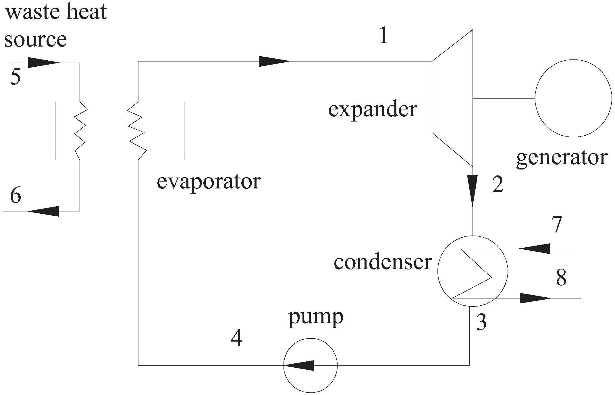
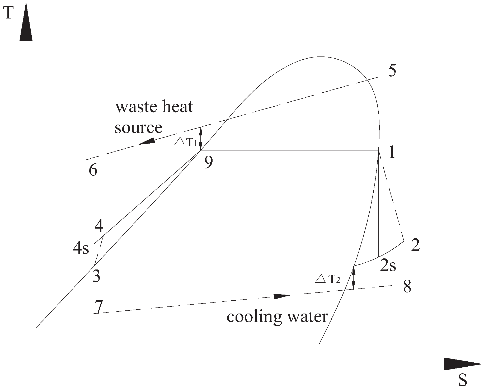
2.1. System Description and Analysis

Figure 1 shows the schematic diagram of the organic Rankine cycle. The basic ORC system contains a working fluid pump, an evaporator driven by low-grade waste heat, an expander, a generator and a condenser. Working fluid with a low boiling point is pumped into the evaporator, where it is heated and vaporized by the low-grade waste heat. The high pressure vapor from the evaporator flows into the expander, where the vapor gets expanded and the work is produced; simultaneously, the expander drives the generator and electric energy is generated. Then, the exhaust vapor from the expander is released into the condenser and condensed by the cooling water. The condensed working fluid is pumped back to the evaporator, and another new cycle begins.
Figure 1. Schematic diagram of the ORC.
Entropy 14 00491 g001
As shown in Figure 2, the thermodynamic process of a basic ORC system can be illustrated in terms of a T-S diagram. The dotted lines of 1–2 and 3–4 stand for the real situations while the solid lines of 1–2 s and 3–4 s stand for the ideal situations (the scale between the two points is magnified). For the investigated ORC, some assumptions are made as follows: (1) the system has reached the steady state; (2) there is no pressure drop in the evaporator, pipes and condenser; (3) the heat loss in the components is neglected; (4) isentropic efficiencies of pump and expander are given. The states of the working fluid at the outlet of condenser and the inlet of expander are saturated liquid and vapor, respectively. Therefore, the evaporation temperature is equal to the inlet temperature of the expander. More detailed processes of the ORC are as follows:
Process 4 to 1: This is an isobaric heating process in the evaporator. The low-grade waste heat source transfers the heat to the working fluid and then the working fluid is vaporized. The heat absorbed by the working fluid in the evaporator would be given by:
Q e v p = m h ( h 5 h 6 ) = m w f ( h 1 h 4 )
where, mh and mwf are the mass flow rate of the waste heat and working fluid, respectively. h5, h6, h4 and h1 are the specific enthalpies of the waste heat and working fluid at the inlet and exit of the evaporator, respectively.
Process 1 to 2: The high pressure vapor working fluid from the evaporator enters the expander, where the heat energy is converted into mechanical power. Then the mechanical power is converted into electric energy by the generator. For the ideal case, the process of 1–2 s is an isentropic process. However, due to the irreversibility in the expander, the expander isentropic efficiency is less than 100%. For the same reason the efficiency of the mechanical power converted into electric energy could never reach 100%. The power generated by the expander could be defined as:
W t = m w f ( h 1 h 2 ) η g = m w f ( h 1 h 2 s ) η s η g
where, h2 is the specific enthalpy of the working fluid at the outlet of the expander, h2s is the specific enthalpy of the working fluid at the outlet of the expander in the ideal case. ηs and ηg are the expander isentropic efficiency and generator efficiency, respectively.
Process 2 to 3: This is an isobaric heat rejection process in the condenser. The exhaust vapor at the outlet of the expander enters the condenser and releases the latent heat into the cooling water. The total heat released by the working fluid in the condenser could be expressed as:
Q c = m w f ( h 2 h 3 )
where, h3 is the specific enthalpy of the working fluid at the outlet of the condenser.
Process 3 to 4: In a real situation, this is a non-isentropic compression process in the pump. The power input by the pump could be expressed as:
W p = m w f ( h 4 s h 3 ) η p = m w f ( h 4 h 3 )
where ηp is the isentropic efficiency of the pump. h4s and h4 are the specific enthalpies of the working fluid at the outlet of the pump for the ideal and actual condition, respectively.
Figure 2. T-S diagram of the ORC.
Entropy 14 00491 g002
The net power output for the ORC could be given by:
W n e t = W t W p
The second law efficiency or exergy efficiency of ORC system could be expressed as:
η I I = W n e t E 5
where E5 is the exergy of the waste heat source at the inlet of the evaporator. It could be evaluated as follows:
E 5 = m h [ h 5 h 0 T 0 ( s 5 s 0 ) ]
where h5 and h0 are the specific enthalpies of the waste heat source at the temperature of T5 and T0, respectively; T0 is the environment temperature; s5 and s0 are the specific entropies of the waste heat source at the temperature of T5 and T0, respectively.
The temperature difference between the critical temperature of the working fluid and the low-grade waste heat temperature could be evaluated by:
Δ T c = T c T 5
where Tc and T5 are the critical temperature of the working fluid and the low-grade waste heat temperature at the inlet of the evaporator, respectively.
The simulation conditions are given in Table 1. Under the given conditions, the maximum second law efficiency is expected in order to make full use of the low-grade waste heat. The second law efficiency for the ORC reflects the capability to recover the work for a given low-grade waste heat. Therefore, the second law efficiency determined by Equation (6) is the objective function to optimize this system.
Table 1. Specifications of the ORC conditions.
DescriptionData
Waste heat source temperature (K)358.15–423.15
Mass flow rate of waste heat source (kg/s)1
Cooling water temperature (K)293.15
Environment temperature (K)293.15
Environment pressure (MPa)0.1
Pinch temperature difference in the evaporator (K)5–20
Pinch temperature difference in the condenser (K)5
Isentropic efficiency of the expander (%)80
Generator efficiency (%)96
Pump isentropic efficiency (%)75

2.2. Calculation Method

The thermodynamic properties of the working fluid and the ORC performance are evaluated with the Engineering Equation Solver (EES) simulation tool [17]. The quadratic approximations method is adopted to optimize the objective function (i.e., the second law efficiency). During the optimization process, the second law efficiency is maximized by adjusting the evaporation temperature.

2.3. Choice of Working Fluids

There are many requirements that the working fluid needs to meet for the ORC, such as stability, non-fouling, non-corrosiveness, non-toxicity and non-flammability [18,19,20,21]. As a matter of fact, not all the desired general criteria could be satisfied in the present ORC design.
Through calculation, we recognize that working fluids with critical temperatures lower than 345 K are not suitable for the limits of subcritical conditions and the given range of the waste heat source temperatures considered in this paper. Twenty eight working fluids with critical temperatures above 345 K are taken into account. The main purpose of this paper is to draw the general conclusions about the thermodynamic performance of the working fluids. Therefore, some other criteria about the working fluids such as the technical and economic aspects and the safety are not taken into account. The properties of 28 working fluids adopted are listed in Table 2.
Table 2. Properties of the considered working fluids.
Working FluidsType of FluidsMolecular Weight (g/mol)Critical Temperature (K)
R143adry84.04345.86
R32wet52.02351.26
Propylenewet42.08365.57
R22wet86.47369.3
R290wet44.1369.89
R134awet102.03374.21
R227eadry170.03374.8
R12isentropic120.91385.12
R152awet66.05386.41
RC318isentropic200.03388.38
R124isentropic136.48395.45
R236faisentropic152.04398.05
R717wet17.03405.4
R600aisentropic58.12407.85
R142bisentropic100.5410.26
R114isentropic170.92418.83
R600dry58.12425.13
R245fadry134.05427.2
R123dry152.93456.83
R601adry72.15460.4
R601dry72.15469.7
R11isentropic137.37471.11
R141bisentropic116.95479.96
R113dry187.38487.21
n-Hexanedry86.17507.4
Methanolwet32.04513.4
Ethanolwet46.07513.9
Tolueneisentropic92.14591.75

3. Results and Discussion

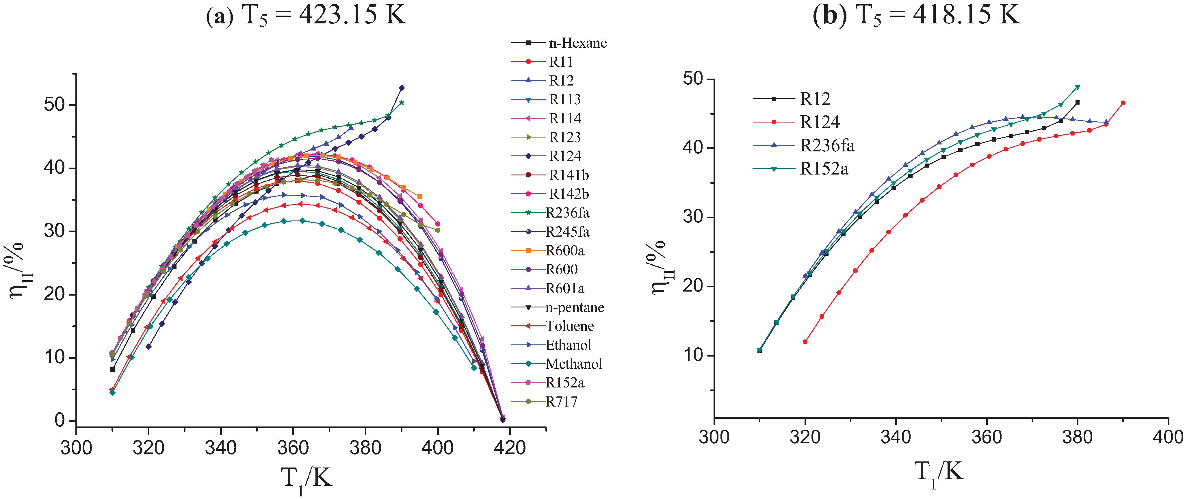
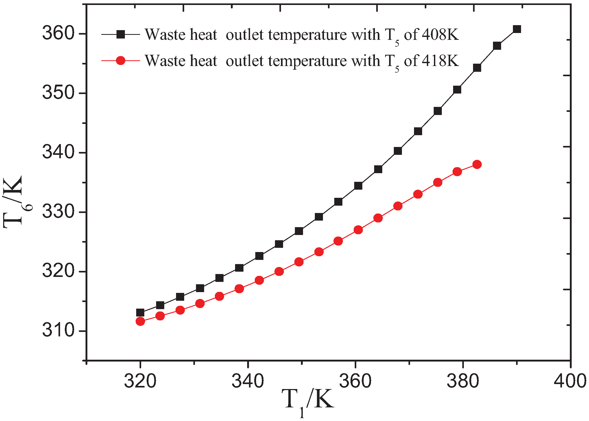
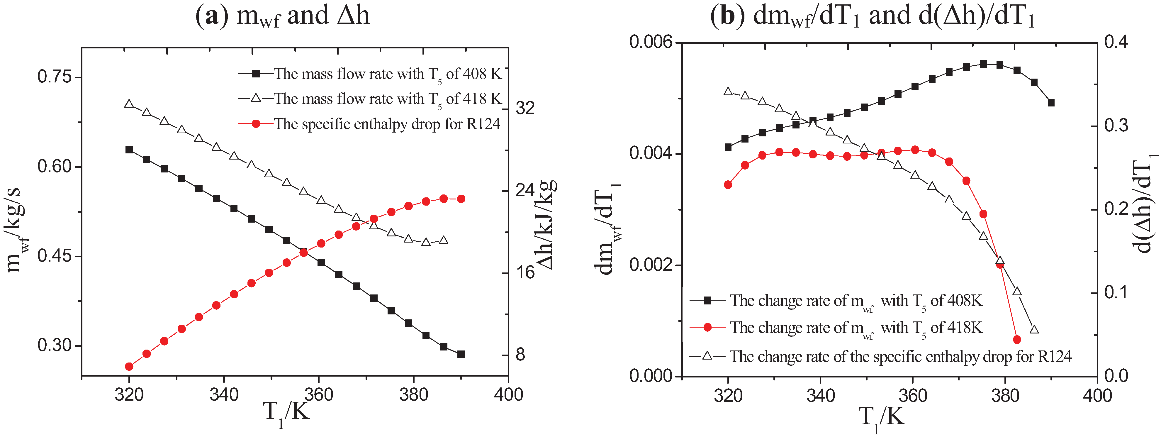
3.1. Influence of Low-Grade Waste Heat Temperature on the OET

The relationships between the second law efficiency of system and the evaporation temperature (T1) are investigated when the rage of waste heat temperatures (T5) is from 423.15 K to 358.15 K with the intervals of 5 K and pinch temperature difference (∆T1) is 5 K in the evaporator. For simplicity and clarity, the relationship of the second law efficiency and the evaporation temperature are shown in Figure 3 for only two waste heat temperatures. Table 3 lists the OET and the second law efficiency for the highest and the lowest waste heat temperatures investigated, respectively.
Figure 3. The relationship of the second law efficiency and the evaporation temperature under different waste heat temperatures.
Entropy 14 00491 g003
As shown in Figure 3a, the second law efficiency of the ORC for most working fluids has a maximum. Therefore, OET can be determined. For example, for the working fluids R717, R600a, R142b and R114, the OETs are 363.7 K, 366.2 K, 366.7 K and 365.6 K, respectively. However, for a few working fluids, such as R12, R152a, R124 and R236fa, the second law efficiency of the cycle will monotonously increase with the increase of evaporation temperature. Therefore, there is no OET for these working fluids.
For working fluids R12, R124 and R152a, the OET does not appear as shown in Figure 3b. The OET appears for the working fluid R236fa. In order to simplify other working fluids with the OET are not described in Figure 3b.
From Table 3, it is observed that ORC has exhibited the OET when the critical temperature of working fluid exceeds the low-grade waste heat temperature. For example, the critical temperature of R600 is about 1.98 K higher than the waste heat temperature and its OET is 365.3 K. However, the critical temperature of the working fluid is lower about 25 K than the waste heat temperature, the OET of the ORC is not found within the range of temperatures investigated, such as for working fluid R236fa.
Under the conditions investigated in this paper, the pinch point is located at point 9 in the evaporator. According to the Equation (6), the efficiency of second law is related to the net power output of ORC. The net power output is almost equal to product of the mass flow rate of the working fluid and the specific enthalpy drop in the expander since the power consumed by the pump can be neglected. Therefore, OET is generally related to the mass flow rates of the working fluids (mwf) and the specific enthalpy drop(Δh) in the expander. The appearance of OET is determined by the change rate of mass flow rate of fluid (dmwf/dT1) and the specific enthalpy drop change rate (d(Δh)/dT1).
Table 3. The OET and the second law efficiency of system (∆T1 = 5K).
Working FluidsT5 = 423.15 KT5 = 358.15 K
∆Tc/KTb/KηII/%∆Tc/KTb/KηII/%
R143a−77.29//−12.29330.929.04
R32−71.89//−6.89328.727.27
Propylene−57.58//7.42328.327.42
R22−53.85//11.15327.927.34
R290−53.26//11.74328.227.61
R134a−48.94//16.06328.127.91
R227ea−48.35//16.65333.220.07
R12−38.03//26.97327.526.91
R152a−36.74------28.26327.627.36
RC318−34.77//30.23328.228.7
R124−27.7------37.333220.1
R236fa−25.1------39.9327.928.1
R717−17.75363.738.2147.2532726.52
R600a−15.3366.242.0849.7327.627.63
R142b−12.89366.742.2352.11327.527.75
R114−4.32365.642.3560.68327.627.79
R6001.98365.341.666.98327.527.59
R245fa4.0536541.9669.05327.627.77
R12333.68362.640.3398.68327.327.57
R601a37.25362.940.51102.25327.427.56
R60146.55362.439.81111.55327.327.3
R1147.96360.438.05112.9632726.94
R141b56.81361.438.93121.81327.227.13
R11364.06361.639.58129.06327.327.41
n-Hexane84.25362.338.13149.25328.325.21
Methanol90.25360.631.73155.25329.220.88
Ethanol90.75359.235.83155.75327.125.68
Toluene168.6362.134.35233.6329.322.03
Note: Sign “/” means working fluid not to be used and “---” does working fluids not to exhibit the OET at given conditions.
The relationship of the outlet temperature of the waste heat source and the evaporation temperature is shown in Figure 4. For R124, the outlet temperature of the waste heat source increases as the evaporation temperature increases. This will lead to a reduction of heat rejection of waste heat source and heat absorption of the ORC system. Simultaneously, the working fluid specific enthalpy at the outlet of the evaporator will also increase and the mass flow rate of working fluid will reduce correspondingly. The specific enthalpy drop of working fluid in expander also will increase with the rise of evaporation temperature. For the working fluids, the enthalpy of saturated vapor usually increases firstly and then decreases with the rise of evaporation temperature. This will lower the rate of increase of the specific enthalpy drop of the working fluid in the expander.
Figure 4. The relationship of the waste heat source outlet temperature and the evaporation temperature for R124.
Entropy 14 00491 g004
The mass flow rates of R124, the specific enthalpy drop in the expander and their change rate with the evaporation temperature are shown in Figure 5. The flow rate of fluid decreases while the specific enthalpy drop in the expander increases with the increase of the evaporation temperature as shown in Figure 5a. The appearance of OET is determined by the change rate of mass flow rate of fluid (dmwf/dT1) and the specific enthalpy drop change rate (d(Δh)/dT1).
Figure 5. Variation of mass flow rates of R124 and the specific enthalpy drop in the expander and their change rate with the evaporation temperature.
Entropy 14 00491 g005
From Figure 5b, it is clear that the change rate of mass flow rate of fluid for the waste heat temperature of 408 K is greater than that for the waste heat temperature of 418 K. In addition, there is a significant increase for the former with the rise of the evaporation temperature. However, the increment of the specific enthalpy drop reduces with the increase of the evaporation temperature for both the two temperatures. Therefore, the OET appears at the temperature of 408 K while it doesn’t appear at the temperature of 418 K.
The ORC with all the working fluids investigated has exhibited the OET when T5 is equal to 358.15 K. It is obvious that the second law efficiency of system shows the different trends with the evaporation temperature under the different waste heat temperatures. When the waste heat temperatures change from 423.15 K to 358.15 K, the OET will appear for some working fluids. Table 4 lists ∆Tc, Tb and ηII for different working fluids when the OETs appeared for the range of waste heat temperatures investigated.
Table 4. The temperature differences between the working fluids critical temperature and the waste heat temperatures (∆Tc) when the OETs appeared (∆T1 = 5 K).
Working Fluids∆Tc/KTb/KηII/%
R143a−12.29330.929.04
R32−16.89336.630.68
Propylene−17.5834735.29
R22−18.85348.635.71
R290−18.26350.637
R134a−18.94353.838.59
R227ea−13.35356.0733.47
R12−23.03359.938.68
R152a−21.74362.240.06
RC318−14.77360.242.76
R124−17.7372.239.09
R236fa−20.1370.744.54
From Table 4, it is clear that the OET appeared when the temperature differences between the critical temperature and the low-grade waste heat temperature are −20.1 K, −17.7 K, −14.77 K, −21.74 K, −23.03 K, −13.35 K, −18.94 K, −18.26 K, −18.85 K, −17.58 K, −16.89 K, −12.29 K for R236fa, R124, RC318, R152a, R12, R227ea, R134a, R290, R22, Propylene, R32 and R143a, respectively. Generally, for the working fluids and the range of the waste heat temperatures investigated, the OET will appear when the critical temperature of working fluids is lower than the temperature of waste heat by 18 ± 5 K. By analyzing the above data, the OET of the ORC is related to the critical temperature of the working fluid and the waste heat temperature.

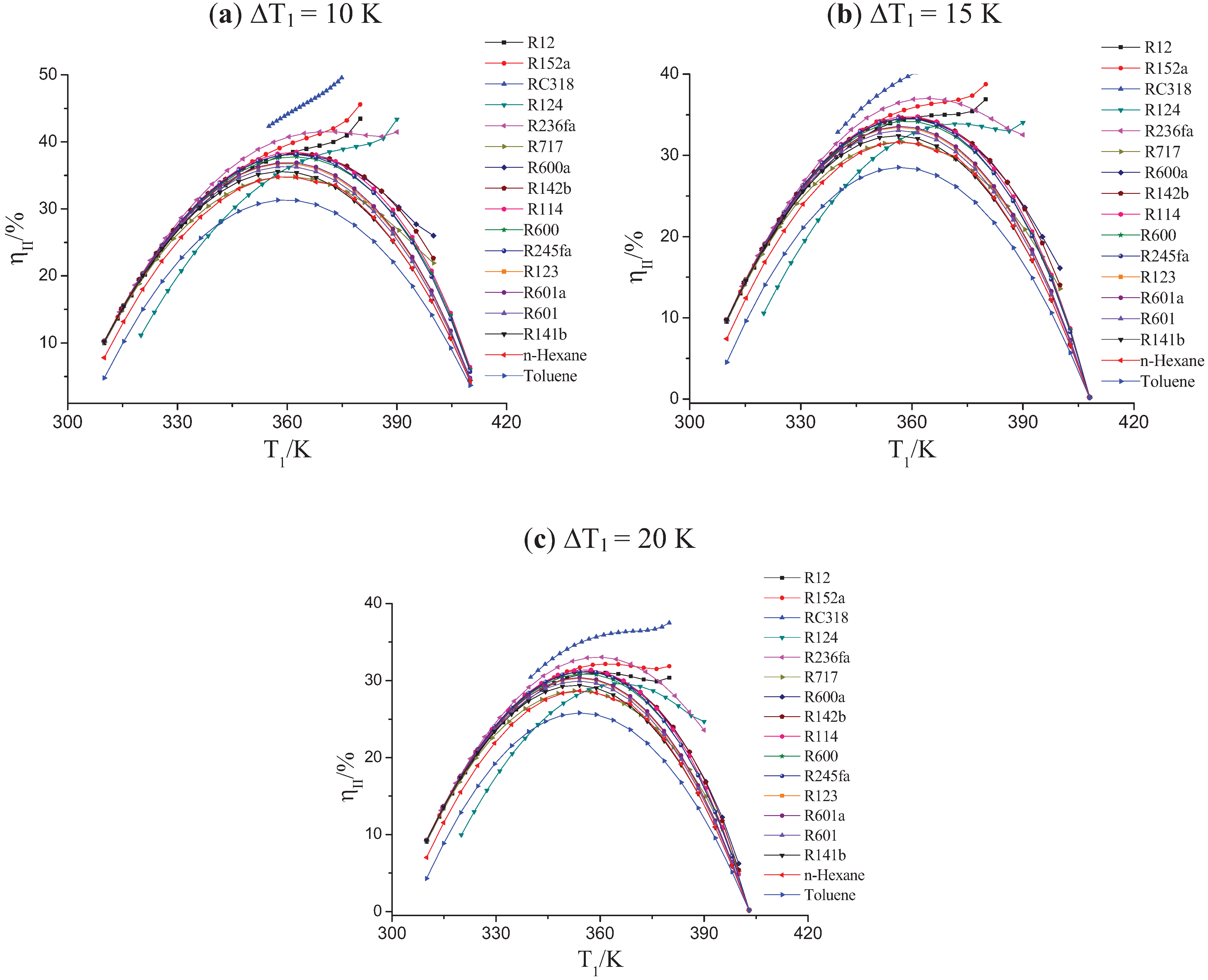
3.2. The Effect of the Pinch Temperature Difference on the OET

Figure 6 presents the relationship of the second law efficiency and the evaporation temperature at the different pinch temperature differences (∆T1) in the evaporator when the low-grade waste heat temperature is kept at 423.15 K. The values of the OET (Tb) and the maximal second law efficiency (ηII) of system are listed in Table 5. If the values of Tb and ηII are not given in the Table, it means that the ORC does not exhibit the OET with these working fluids.
For each working fluid, the temperature difference between the critical temperature and the low-grade waste heat temperature (∆Tc) is constant. From the Figure 3a, Figure 6a, Table 3 and Table 5, it could be seen that the ORC with R236fa exhibits the OET when the pinch temperature difference ∆T1 is improved from 5 K to 10 K. When the value of ∆T1 gets increased to 15 K, the similar situation happens on R124, as shown in the Figure 6b and Table 5. The Figure 6c and Table 5 illustrate that the ORC with R12 and R152a exhibits the OETs of 359.9 K and 362.3 K, respectively. Therefore, it is clearly shown that the OET of the system is related to not only the waste heat temperature but also the pinch temperature difference (∆T1) in the evaporator.
Figure 6. The relationship of the second law efficiency and the evaporation temperature under different pinch temperature differences.
Entropy 14 00491 g006
The value of the maximal second law efficiency gets decreased with the increase of pinch temperature difference in the evaporator for the same working fluid, as shown in Table 5. For example, the maximal second law efficiency of the ORC for toluene gets decreased from 31.36% to 28.51% when the pinch temperature difference increases from 10 K to 15 K. Because the irreversibility in the ORC will increase with the increment of the pinch temperature difference in the evaporator, the second law efficiency of system will get decreased. From Table 5, it is known that the maximal value of second law efficiency of the ORC is 41.53% for R236fa and the minimum is 25.80% for toluene. These results will help to select working fluid in engineering application.
Table 5. The OET and the maximal second law efficiency of system (T5 = 423.15 K, ∆T1 = 10 K, 15 K, 20 K).
Working Fluids∆Tc/K∆T1 = 10 K∆T1 = 15 K∆T1 = 20 K
Tb /KηII/%Tb /KηII/%Tb /KηII/%
R12−38.03------------359.931.05
R152a−36.74------------362.332.16
RC318−34.77------------------
R124−27.7------372.233.88365.729.60
R236fa−25.1370.741.53364.237.02359.433.05
R717−17.75360.134.82356.931.65353.828.66
R600a−15.3362.438.1935934.56355.731.17
R142b−12.89362.838.29359.234.63355.931.22
R114−4.32362.238.47358.934.82355.731.41
R6001.98361.937.80358.634.24355.430.90
R245fa4.05361.738.14358.534.56355.431.20
R12333.68359.736.80356.833.4735430.30
R601a37.25359.936.9535733.58354.230.40
R60146.55359.536.35356.633.06353.829.95
R141b56.81358.635.60355.932.43353.229.41
n-Hexane84.25359.634.80356.931.64354.328.64
Toluene168.6359.631.3635728.51354.525.80

4. Conclusions

The effects of the waste heat temperature and the pinch temperature difference in the evaporator on the OET in ORC were discussed. The quadratic approximations method was used to optimize the second law efficiency of the ORC with 28 different working fluids. Based on the analysis in this paper, the following conclusions could be made:
The OET of the ORC is related to the waste heat temperature, the critical temperature of working fluids and the pinch temperature difference in the evaporator.
When the critical temperature of working fluids is lower than the temperature of waste heat by 18 ± 5 K and the pinch temperature difference in the evaporator is fixed at 5 K, OET in ORC will appear for the temperature ranges investigated. When the critical temperature of working fluids exceeds the temperature of waste heat, the ORC always exhibits the OET.
The ORC with some working fluids also exhibits the OET when the pinch temperature difference in evaporator is greater than a certain value and the temperature of the waste heat is kept at 423.15 K. The optimal second law efficiency of the ORC gets decreased with the increase of pinch temperature difference in the evaporator.
However, this paper focuses only on the second law efficiency and this criterion is not sufficient for a proper selection of the working fluid in ORC. The environmental and economical aspects in selecting the working fluids for the ORC will be considered in the future.

Acknowledgments

This work was supported by National Basic Research Program of China (973 Program) under Grant No. 2011CB710701, Specialized Research Fund for the Doctoral Program of Higher Education of China under Grant No.20090191110016 and the Fundamental Research Funds for the Central Universities under Grant No. CDJXS10140005.

References

  1. Wei, D.H.; Lu, X.S.; Lu, Z.; Gu, J.M. Performance analysis and optimization of organic Rankine cycle (ORC) for waste heat recovery. Energ. Convers. Manag. 2007, 48, 1113–1119. [Google Scholar] [CrossRef]
  2. Liu, B.T.; Chien, K.H.; Wang, C.C. Effect of working fluids on organic Rankine cycle for waste heat recovery. Energy 2004, 29, 1207–1217. [Google Scholar] [CrossRef]
  3. Heberle, F.; Brüggemann, D. Exergy based fluid selection for a geothermal Organic Rankine Cycle for combined heat and power generation. Appl. Therm. Eng. 2010, 30, 1326–1332. [Google Scholar] [CrossRef]
  4. Guo, T.; Wang, H.X.; Zhang, S.J. Comparative analysis of CO2-based transcritical Rankine cycle and HFC245fa-based subcritical organic Rankine cycle using low-temperature geothermal source. Sci. China 2010, 53, 1638–1646. [Google Scholar] [CrossRef]
  5. Kosmadakis, G.; Manolakos, D.; Papadakis, G. Parametric theoretical study of a two-stage solar organic Rankine cycle for RO desalination. Renew. Energ. 2010, 35, 989–996. [Google Scholar] [CrossRef]
  6. Facao, J.; Oliveira, A.C. Analysis of energetic, design and operational criteria when choosing an adequate working fluid for small ORC systems. In Proceedings of the ASME International Mechanical Engineering Congress and Exposition, Lake Buena Vista, FL, USA, November 2009.
  7. Quoilin, S.; Declaye, S.; Tchanche, B.F.; Lemort, V. Thermo-economic optimization of waste heat recovery Organic Rankine Cycles. Appl. Therm. Eng. 2011, 31, 2885–2893. [Google Scholar] [CrossRef]
  8. Lakew, A.A.; Bolland, O. Working fluids for low-temperature heat source. Appl. Therm. Eng. 2010, 30, 1262–1268. [Google Scholar] [CrossRef]
  9. Wang, J.L.; Zhao, L.; Wang, X.D. A comparative study of pure and zeotropic mixtures in low-temperature solar Rankine cycle. Appl. Energ. 2010, 87, 3366–3373. [Google Scholar] [CrossRef]
  10. Xu, R.J.; He, Y.L. A vapor injector-based novel regenerative organic Rankine cycle. Appl. Therm. Eng. 2011, 31, 1238–1243. [Google Scholar] [CrossRef]
  11. Zhang, S.J.; Wang, H.X.; Guo, T. Performance comparison and parametric optimization of subcritical Organic Rankine Cycle (ORC) and transcritical power cycle system for low-temperature geothermal power generation. Appl. Energ. 2011, 88, 2740–2754. [Google Scholar]
  12. Dai, Y.P.; Wang, J.F.; Lin, G. Parametric optimization and comparative study of organic Rankine cycle (ORC) for low grade waste heat recovery. Energ. Convers. Manag. 2009, 50, 576–582. [Google Scholar] [CrossRef]
  13. Saleh, B.; Koglbauer, G.; Wendland, M.; Fischer, J. Working fluids for low temperature organic Rankine cycles. Energy 2007, 32, 1210–1221. [Google Scholar] [CrossRef]
  14. Mago, P.J.; Chamra, L.M.; Somayaji, C. Performance analysis of different working fluids for use in organic Rankine cycles. Proc. IME J. Power Energ. 2007, 221, 255–264. [Google Scholar] [CrossRef]
  15. Young, J.B.; Minsung, K.; Chang, K.C.; Sung, J.K. Power-based performance comparison between carbon dioxide and R125 transcritical cycles for a low grade heat source. Appl. Energ. 2011, 88, 892–898. [Google Scholar]
  16. Roy, J.P.; Mishra, M.K.; Misra, A. Performance analysis of an Organic Rankine Cycle with superheating under different heat source temperature conditions. Appl. Energ. 2011, 88, 2995–3004. [Google Scholar] [CrossRef]
  17. Engineering Equation Solver, professional version, EES. F-Chart Software: Madision, WI, USA, 2006.
  18. Madhawa Hettiarachchi, H.D.; Golubovic, M.; Worek, W.M.; Ikegami, Y. Optimum design criteria for an Organic Rankine cycle using low-temperature geothermal heat sources. Energy 2007, 32, 1698–1706. [Google Scholar] [CrossRef]
  19. Papadopoulos, A.I.; Stijepovic, M.; Linke, P. On the systematic design and selection of optimal working fluids for Organic Rankine Cycles. Appl. Therm. Eng. 2010, 30, 760–769. [Google Scholar] [CrossRef]
  20. Tchanche, B.F.; Papadakis, G.; Lambrinos, G.; Frangoudakis, A. Fluid selection for a low-temperature solar organic Rankine cycle. Appl. Therm. Eng. 2009, 29, 2468–2476. [Google Scholar] [CrossRef]
  21. Chen, H.J.; Goswami, D.Y.; Stefanakos, E.K. A review of thermodynamic cycles and working fluids for the conversion of low-grade heat. Renew. Sustain. Energ. Rev. 2010, 14, 3059–3067. [Google Scholar] [CrossRef]

