Association of Finite-Time Thermodynamics and a Bond-Graph Approach for Modeling an Endoreversible Heat Engine

Abstract
:1. Introduction


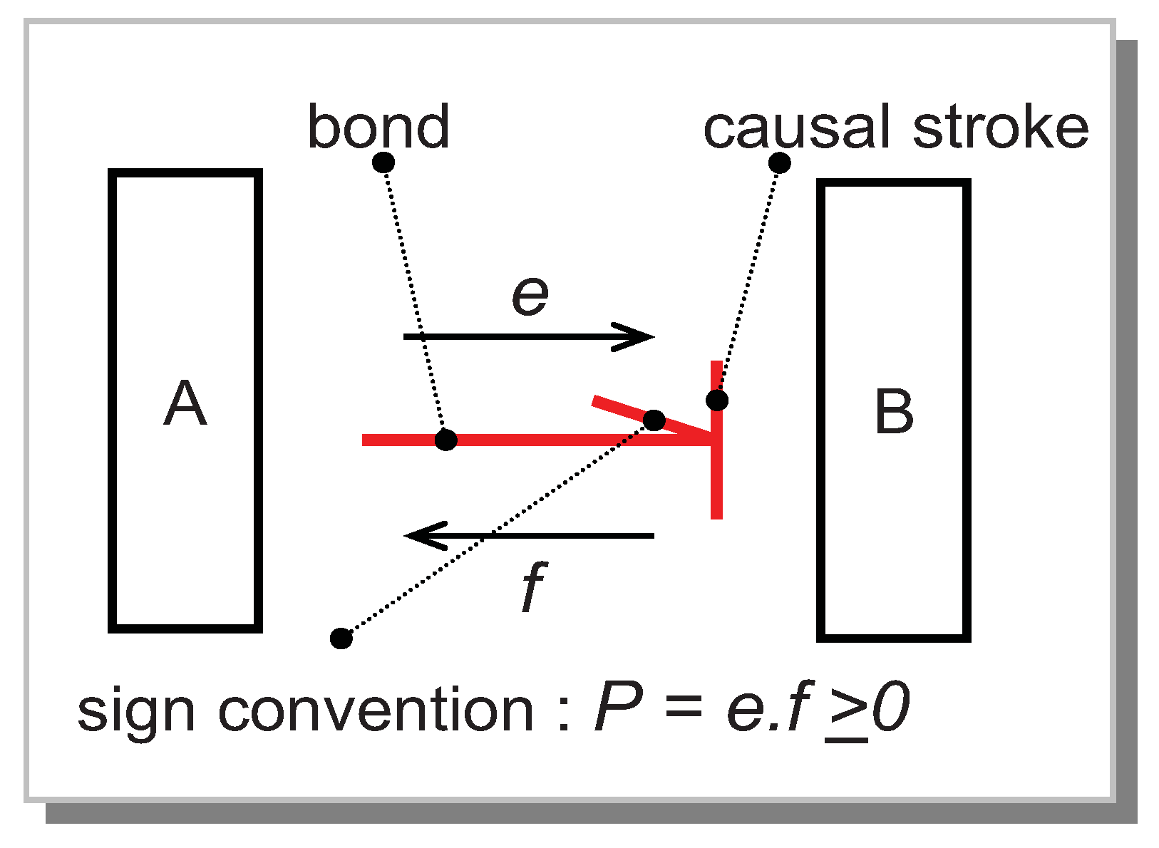
| Power | Effort | Flow |
|---|---|---|
| Electrical | Voltage [V] | Current [A] |
| Mechanical, translation | Force [N] | Linear velocity [m/s] |
| Mechanical, rotation | Torque [N.m] | Angular velocity [rad/s] |
| Fluid | Pressure [N/m²] | Volumetric flow rate [m3/s] |
| Thermal | Temperature [K] | Entropy flow rate [W/K] |
| Chemical | Chemical potential [J/mol] | molar flux [mol/s] |
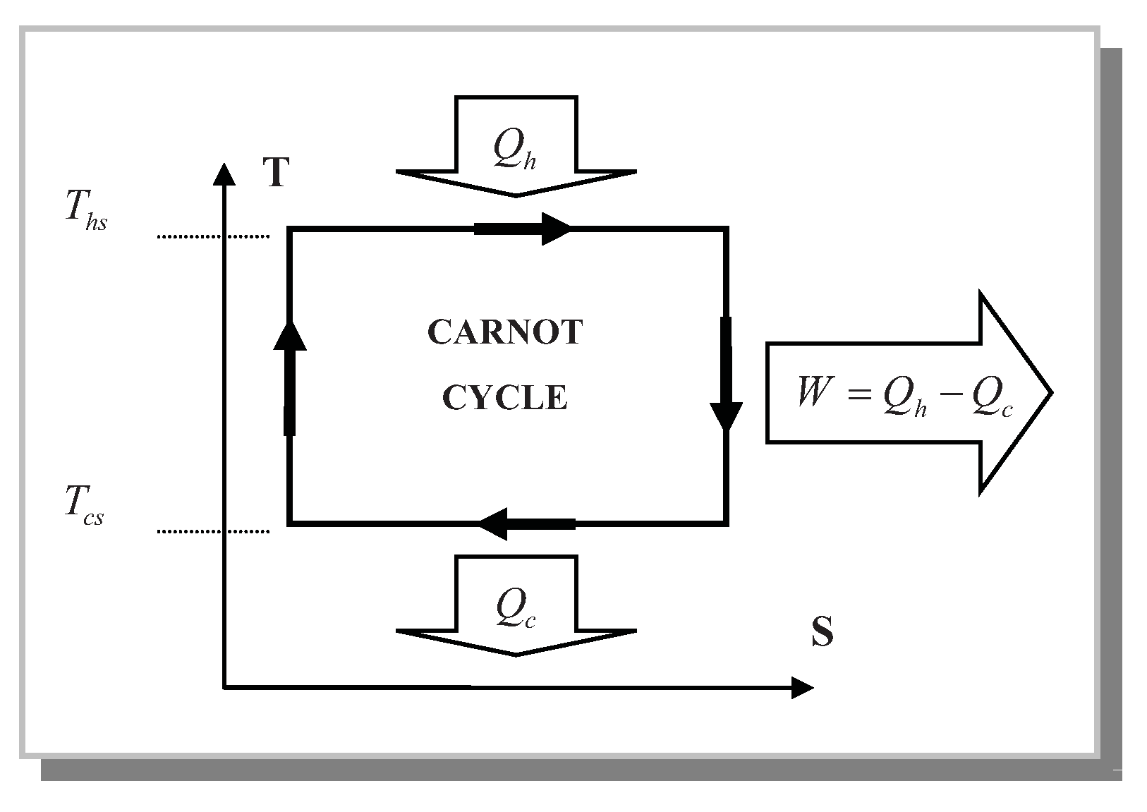
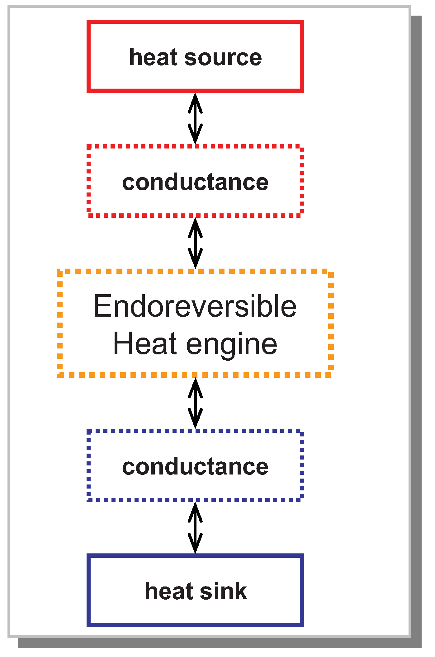
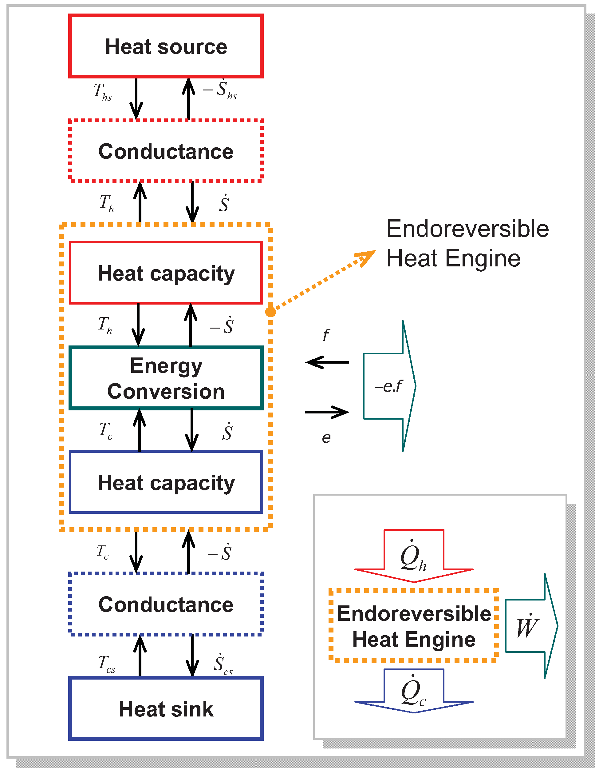
2. Modeling of Endoreversible Heat Engine at Steady State

2.1. Energy Balance with Finite Heat Transfer Constraint
- The temperatures of heat source and heat sink are constant (Ths and Tcs).
- Heat exchangers have constant global thermal conductances (Kh and Kc).
- The machine operates at steady state.
2.2. Choice of the Control Variable of the Endoreversible Heat Engine

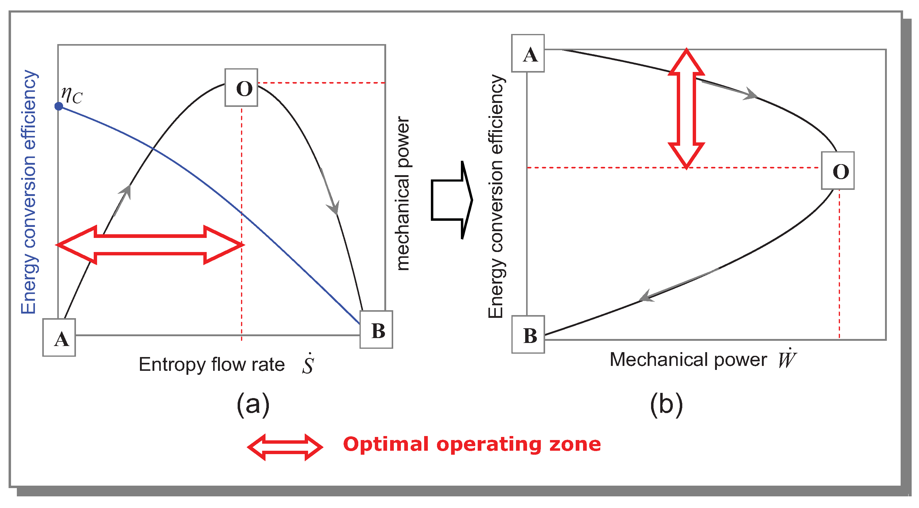
2.3. Operating Range of the Endoreversible Heat Engine

2.4. Determination of the Maximum Mechanical Power and the Associated Efficiency
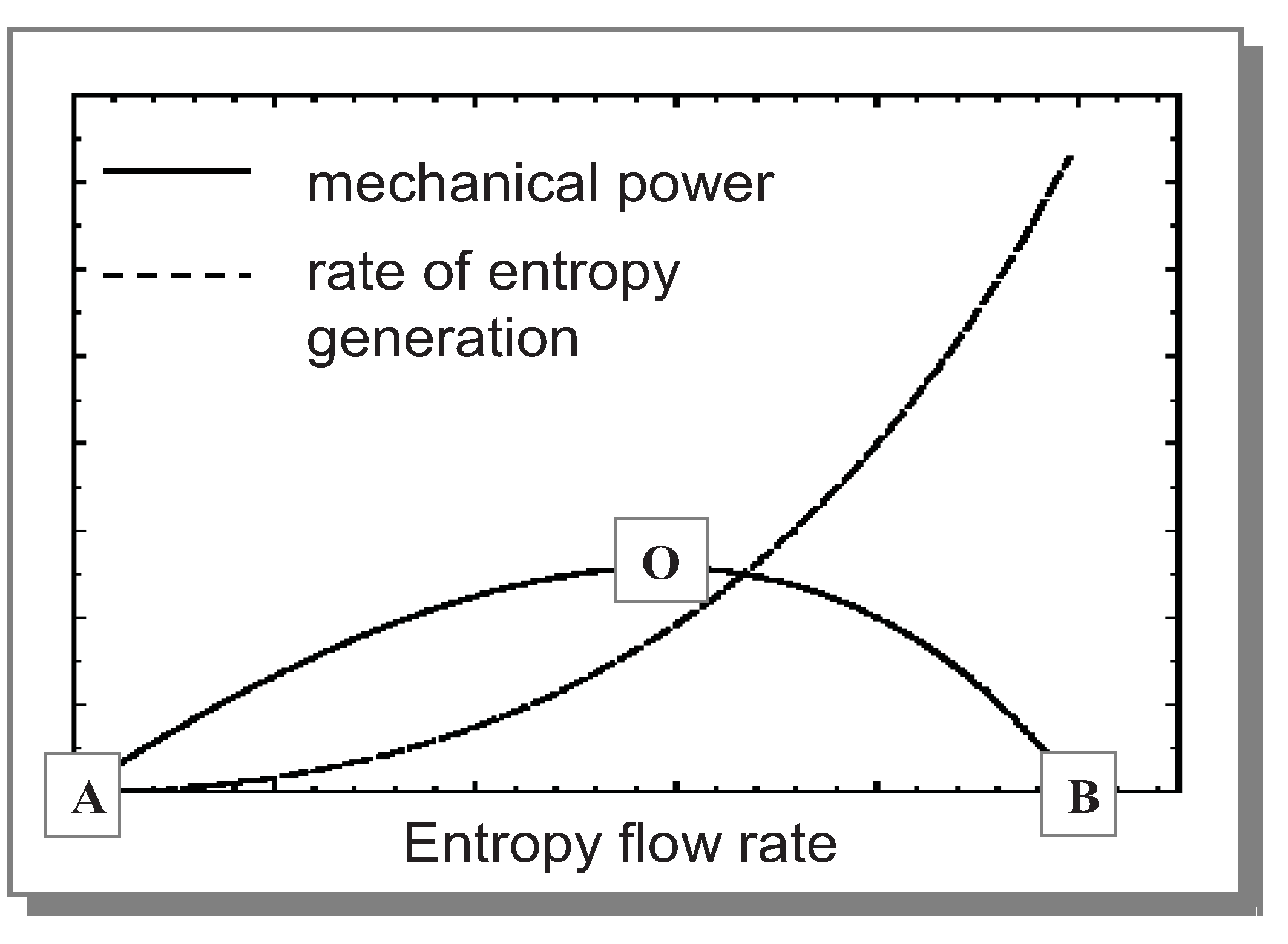
2.5. Analysis of the Rate of Entropy Generation

3. Conclusions and Outlook
- The expressions of all the variables as a function of the control variable.
- The range of variation of the control variable.
- The parametric equations of the operating curve of the machine.
- The characteristics of the optimal point according to the maximum mechanical power (CNCA efficiency,…). This approach is proposed in opposition to the great majority of existing results, using temperature as control variable (that is to say intensive variable and not extensive one).
Nomenclature
| Variable | Unit | Description |
| Ths | K | Temperature of the heat source |
| Tcs | K | Temperature of the heat sink |
| Th | K | Hot side temperature of the endoreversible converter |
| Tc | K | Cold side temperature of the endoreversible converter |
| Ṡhs | W/K | Entropy flow rate transferred from heat source to endoreversible converter |
| Ṡcs | W/K | Entropy flow rate transferred from endoreversible converter to heat sink |
| Ṡ | W/K | Entropy flow rate involved in energy converter |
| Ṡsc | W/K | Cutoff entropy flow rate |
| W/K | Rate of total entropy generation within the endoreversible heat engine | |
| Kh | W/K | Global thermal conductance of the heat exchanger at hot side |
| Kc | W/K | Global thermal conductance of the heat exchanger at cold side |
| W | Thermal power exchanged between the heat source and the endoreversible converter | |
| W | Thermal power exchanged between the heat sink and the endoreversible converter | |
| Ẇ | W | Mechanical power |
| Ẇmax | W | Maximum mechanical power |
| η1 | -- | Energy conversion efficiency |
| ηC | -- | Carnot efficiency |
| ηCNCA | -- | Chambadal-Novikov-Curzon-Ahlborn efficiency |
References
- Chambadal, P. Les Centrales Nucléaires; Armand Colin: Paris, France, 1957; pp. 41–58. [Google Scholar]
- Novikov, I.I. The efficiency of atomic power station. J. Nucl. Energy 1958, 7, 125–128. [Google Scholar]
- Feidt, M. Thermodynamique et Optimisation Energétique des Systèmes et Procédés; Lavoisier: Paris, France, 1987. [Google Scholar]
- Jou, D.; Casas-Vasquez, J.; Lebon, G. Extended Irreversible Thermodynamics; Springer Verlag: Berlin, Germany, 2000. [Google Scholar]
- Andresen, B. Finite Time Thermodynamics; Physics Laboratory, University of Copenhagen: Copenhagen, Denmark, 1983. [Google Scholar]
- Bejan, A. Entropy generation minimization: The new thermodynamics of finite size, and finite time processes. J. Appl. Phys. 1997, 79, 1191–1218. [Google Scholar] [CrossRef]
- Bejan, A.; Tsatsaronis, G.; Moran, M. Thermal Design and Optimization; John Wiley & Sons: New York, NY, USA, 1996. [Google Scholar]
- Goth, Y.; Feidt, M. Recherche sur les conditions optimales de fonctionnement des pompes à chaleur ou machines à froid associées à un cycle de Carnot endoreversible. C. R. Acad. Sci. 1986, 303, 113–122. [Google Scholar]
- Chen, L.; Zhou, J.; Sun, F.; Wu, C. Ecological optimization for generalized irreversible Carnot engines. Appl. Energy 2004, 77, 327–338. [Google Scholar] [CrossRef]
- Chen, L.; Wu, C.; Sun, F. Finite time thermodynamic optimization or entropy generation minimization of energy systems. J. Non-Equilib. Thermodyn. 1999, 24, 327–359. [Google Scholar] [CrossRef]
- Chen, L.; Wu, C.; Sun, F.; Chen, W. Optimal performance of an endoreversible Carnot heat pump. Energy Convers. Manag. 1997, 38, 1439–1443. [Google Scholar] [CrossRef]
- Chen, L.; Wu, C.; Sun, F.; Chen, W. General performance characteristics of finite speed Carnot refrigerator. Appl. Therm. Eng. 1996, 16, 299–303. [Google Scholar]
- Wu, C.; Kiang, R.L. Finite-time thermodynamic analysis of a Carnot engine with internal irreversibility. Energy 1992, 17, 1173–1178. [Google Scholar] [CrossRef]
- Feidt, M. Optimal thermodynamics—New upperbounds. Entropy 2009, 11, 529–547. [Google Scholar] [CrossRef]
- Feidt, M.; Costea, M.; Petre, C.; Petrescu, S. Optimization of the direct Carnot cycle. Appl. Therm. Eng. 2007, 27, 829–839. [Google Scholar] [CrossRef]
- Feidt, M. Reconsideration of criteria and modeling in order to optimize the efficiency of irreversible thermomechanical heat engines. Entropy 2010, 12, 2470–2484. [Google Scholar] [CrossRef]
- Curzon, F.L.; Ahlborn, B. Efficiency of a Carnot engine at maximum power conditions. Am. J. Phys. 1975, 53, 570–573. [Google Scholar]
- Durmayaza, A.; Sogub, O.S.; Sahin, B.; Yavuz, H. Optimization of thermal systems based on finite-time thermodynamics and thermoeconomics. Prog. Energy Combust. Sci. 2004, 30, 175–217. [Google Scholar] [CrossRef]
- Kodal, A.; Sahin, B.; Yilmaz, T. A comparative performance analysis of irreversible Carnot heat engines under maximum power density and maximum power conditions. Energy Convers. Manag. 2000, 41, 235–248. [Google Scholar] [CrossRef]
- de Vos, A. Endoreversible thermoeconomics. Energy Convers. Manag. 1995, 36, 1–5. [Google Scholar] [CrossRef]
- Tyagi, S.K.; Chen, J.; Kaushik, S.C. Thermoeconomic optimization and parametric study of an irreversible Stirling heat pump cycle. Int. J. Therm. Sci. 2004, 43, 105–112. [Google Scholar] [CrossRef]
- Angulo-Brown, F. An ecological optimization criterion for finite-time heat engines. J. Appl. Phys. 1991, 69, 7465:1–7465:5. [Google Scholar] [CrossRef]
- Chen, L.; Zhou, J.; Sun, F.; Wu, C. Ecological optimization for generalized irreversible Carnot engines. Appl. Energy 2004, 77, 327–338. [Google Scholar] [CrossRef]
- Vijay, P.; Samantaray, A.K.; Mukherjee, A. A bond graph model-based evaluation of a control scheme to improve the dynamic performance of a solid oxide fuel cell. Mechatronics 2009, 19, 489–502. [Google Scholar] [CrossRef]
- Onsager, L. Reciprocal relations in irreversible processes. I. Phys. Rev. 1931, 37, 405–426. [Google Scholar] [CrossRef]
- Onsager, L. Reciprocal relations in irreversible processes. II. Phys. Rev. 1931, 38, 2265–2279. [Google Scholar] [CrossRef]
- Lenoir, B.; Michenaud, J.; Dauscher, A. Thermoélectricité: Des Principes aux Applications. Technique de l’ingénieur 2010. Référence K730. [Google Scholar]
© 2012 by the authors; licensee MDPI, Basel, Switzerland. This article is an open access article distributed under the terms and conditions of the Creative Commons Attribution license (http://creativecommons.org/licenses/by/3.0/).
Share and Cite
Dong, Y.; El-Bakkali, A.; Descombes, G.; Feidt, M.; Périlhon, C. Association of Finite-Time Thermodynamics and a Bond-Graph Approach for Modeling an Endoreversible Heat Engine. Entropy 2012, 14, 642-653. https://doi.org/10.3390/e14040642
Dong Y, El-Bakkali A, Descombes G, Feidt M, Périlhon C. Association of Finite-Time Thermodynamics and a Bond-Graph Approach for Modeling an Endoreversible Heat Engine. Entropy. 2012; 14(4):642-653. https://doi.org/10.3390/e14040642
Chicago/Turabian StyleDong, Yuxiang, Amin El-Bakkali, Georges Descombes, Michel Feidt, and Christelle Périlhon. 2012. "Association of Finite-Time Thermodynamics and a Bond-Graph Approach for Modeling an Endoreversible Heat Engine" Entropy 14, no. 4: 642-653. https://doi.org/10.3390/e14040642