Article

Entropy Generation in a Couple Stress Fluid Flow Through a Vertical Channel Filled with Saturated Porous Media

by
Oluwole Daniel Makinde
1 and
Adetayo Samuel Eegunjobi
2,*
1
Faculty of Military Science, Stellenbosch University, Private Bag X2, Saldanha 7395, South Africa
2
Department of Mathematics and Statistics, Polytechnic of Namibia, Namibia's University of Science and Technology, Private Bag 13388, 13 Storch Street, Windhoek 9000, Namibia
*
Author to whom correspondence should be addressed.
Entropy 2013, 15(11), 4589-4606; https://doi.org/10.3390/e15114589
Submission received: 16 September 2013 / Revised: 6 October 2013 / Accepted: 21 October 2013 / Published: 25 October 2013
(This article belongs to the Special Issue Entropy and the Second Law of Thermodynamics)

Abstract

:
The present work investigates numerically the inherent irreversibility in a steady flow of a couple stress fluid through a vertical channel packed with saturated porous substances. The First and Second Laws of Thermodynamics are applied to analyze the problem. The nonlinear governing equations in Cartesian coordinates are obtained and solved numerically using shooting methods together with a Runge-Kutta Fehlberg integration scheme. The entropy generation number is computed by utilizing the velocity and temperature profiles. The effects of various physical parameters on the flow and heat transfer characteristics, as well as entropy generation rates and Bejan number, are investigated through graphs.

Graphical Abstract

1. Introduction

Studies related to channel flow and heat transfer characteristics of couple-stress fluids not only present theoretical problem challenges, but also find several applications in many industrial processes such as the extrusion of polymer fluids, solidification of liquid crystals, cooling of metallic plates in a bath, colloidal solutions, etc. These fluids are capable of describing various types of lubricants, blood and suspension fluids. Stokes [1] introduced the theory of couple stress fluids. The main feature of couple stresses is to introduce a size dependent effect. Classical continuum mechanics neglects the size effect of material particles within the continua. However, in some important cases such as fluid flow with suspended particles, this cannot be true and a size dependent couple-stress theory is needed. The spin field due to micro-rotation of freely suspended particles sets up an anti-symmetric stress, known as couple-stress, and thus forms a couple-stress fluid. A review of couple stress fluid dynamics was reported by Stokes [2]. Srinivasacharya and Srikanth [3] studied the effect of couple stresses on the flow in a constricted annulus. Moreover, the analysis of convective transport in a porous medium with the inclusion of non-Darcian effects has also been a matter of study in recent years. The inertia effect is expected to be important at a higher flow rate and it can be accounted for through the addition of a velocity squared term in the momentum equation, which is known as the Forchheimer’s extension of Darcy’s law. A detailed review of convective heat transfer in Darcy and non-Darcy porous medium can be found in the book by Nield and Bejan [4]. Postelnicu [5] investigated the combined effects of magnetic fields, thermal-diffusion and diffusion-thermo on heat and mass transfer by natural convection from vertical surfaces in porous media. Other studies on flow and heat transfer in porous media can be found in [6,7,8]. Meanwhile, the current trend of analysing flow and heat transfer is to apply a Second Law (of Thermodynamics) analysis, and its design-related concept of entropy generation minimization (EGM). Entropy generation is associated with thermodynamic irreversibility, which presents in all flow and heat transfer processes. Bejan [9] pioneered theoretical work on entropy generation in flow systems. He showed that by minimizing the entropy, the efficiency of a thermal system could be improved. Thereafter, several authors [10,11,12] have analyzed different problems to study the entropy effects on thermal systems and to find ways to minimize them. Mahmud and Fraser [13] applied the Second Law analysis to fundamental convective heat transfer problems. Tasnim et al. [14] examined entropy generation rate in an isothermal porous two dimensional channel with magnetic field effects. Chauhan and Kumar [15] numerically analysed the heat transfer and inherent irreversibility in a compressible fluid flow through a channel partially filled with porous medium. Eegunjobi and Makinde [16] studied the combined effect of buoyancy force and Navier slip on entropy generation in a vertical porous channel. Sheng et al. [17] investigated systematically the effects of Rayleigh number, curvature of annulus and Prandtl number on flow pattern, temperature distribution and entropy generation for natural convection inside vertically concentric annuli with the aid of the lattice Boltzmann method. Sheng [18] investigated for the first time, the entropy generation of double-diffusive convection in the presence of rotation.
To the best knowledge of the authors, the buoyancy effect on the inherent irreversibility in a couple stress fluid flows through a vertical channel filled with saturated porous media has not been reported yet in the literature. The main objective of this present study is to theoretically analyze the entropy generation rate in a couple stress fluid flows through a vertical channel filled with saturated porous media in the presence of buoyancy force. The mathematical formulation of the problem is established in sections two and three. Using a shooting method coupled with a Runge-Kutta Fehlberg integration scheme the boundary value problem is tackled numerically. Both numerical and graphical results for velocity, temperature, entropy generation rate and Bejan number are presented and discussed quantitatively with respect to various parameters embedded in the system in section four. Finally, in Section 5, we give the concluding remarks.

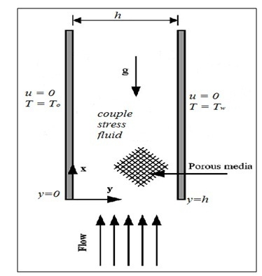
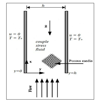
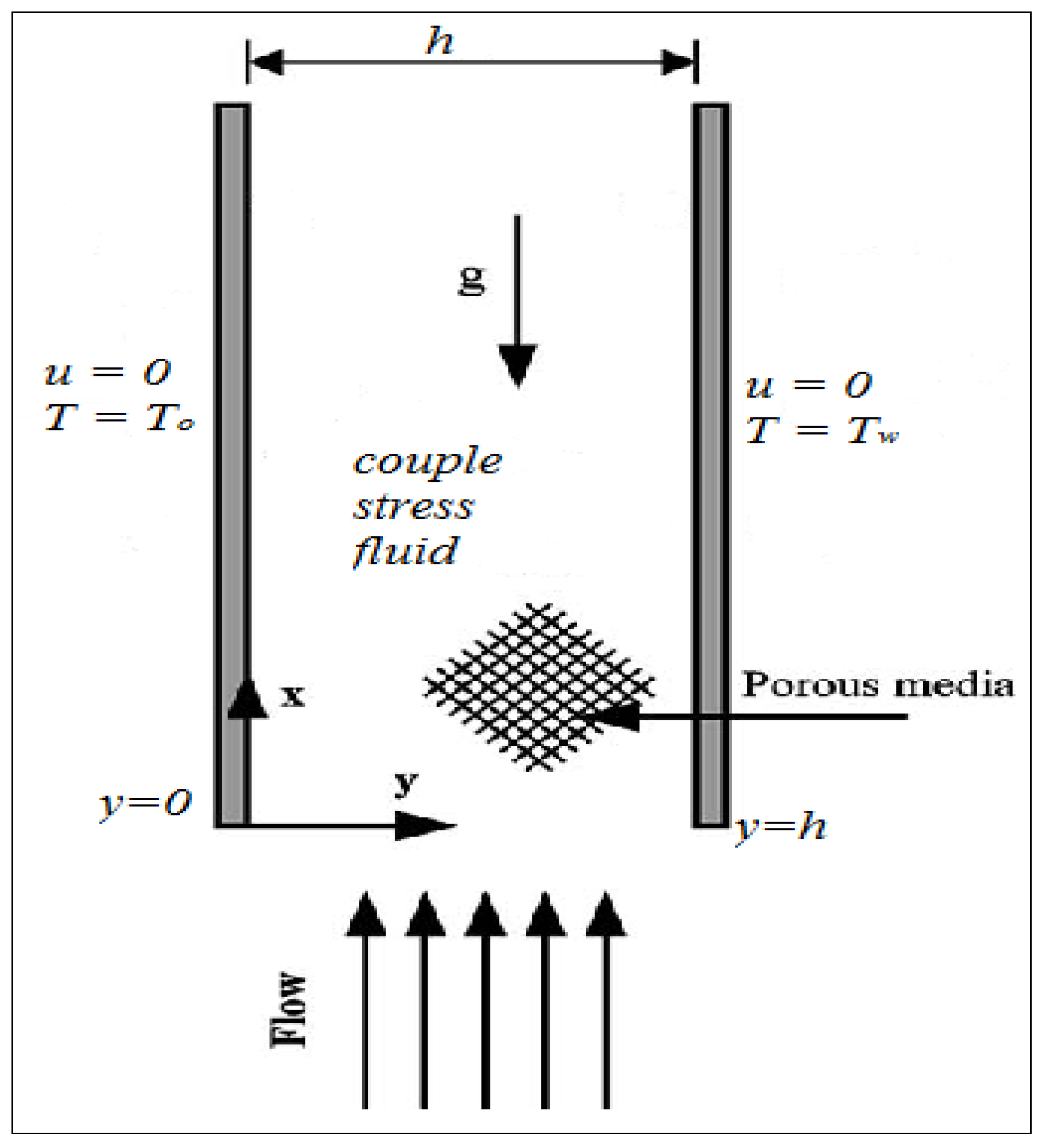
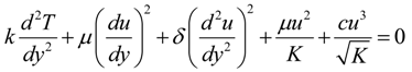
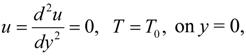
2. Mathematical Model
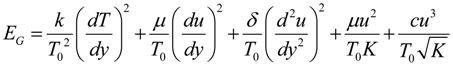
Consider the steady flow of an incompressible viscous couple stress fluid through a vertical channel filled with porous media as depicted in Figure 1, where the left channel wall is placed at temperature T0 while the right wall is placed at temperature Tw such that T0 < Tw.
Figure 1. Schematic diagram of the problem under consideration.
Entropy 15 04589 g001
Assuming Brinkman–Forchheimer flow model, the governing equations of momentum and energy under Boussinesq’s approximation are given as [1,8,12,16]:
Entropy 15 04589 i001
Entropy 15 04589 i002
with:
Entropy 15 04589 i003
Entropy 15 04589 i004
where u is the axial velocity, h is the channel width, μ is the dynamic viscosity, ρ is the fluid density, T is the fluid temperature, cp specific heat at constant pressure, k is the thermal conductivity of the fluid, K is the porous media permeability, c is the empirical constant in the second order (porous inertia) resistance such that c = 0 corresponds to the Darcy law, δ is the fluid particle size effect due to couple stresses. Introducing the following dimensionless variables:
Entropy 15 04589 i005
Substituting Equation (5) into Equations (1)–(4), we obtain the dimensionless governing equations as:
Entropy 15 04589 i006
Entropy 15 04589 i007
with:
Entropy 15 04589 i008
Entropy 15 04589 i009
where Gr is the Grashof number due to buoyancy effect, Ec is the Eckert number, Pr is the Prandtl number, λ is the couple stress parameter, A is the axial pressure gradient parameter, S is the porous media shape factor parameter and M the second order porous media resistance parameter. Other physical quantities of practical significance in this work are the skin friction coefficient Cf and the local Nusselt number Nu, which are expressed as:
Entropy 15 04589 i010
where τw is the wall shear stress and qw is the heat flux at the channel walls given by:
Entropy 15 04589 i011
The set of Equations (6)–(7) together with the boundary conditions in Equations (8)–(9) form a two point boundary value problem and are solved numerically using a shooting algorithm together with a Runge-Kutta Fehlberg integration scheme [19]. This method involves transforming Equations (6)–(9) into a set of initial value problems which contain some unknown initial values that need to be determined by guessing, after which a Runge-Kutta Fehlberg integration scheme is employed to solve the set of initial valued problems until the given boundary conditions are satisfied. The entire computation procedure is implemented using a program written and carried out using the MAPLE computer language. From the process of numerical computation, the fluid velocity and temperature, the skin friction coefficient and the Nusselt number, are determined for a given set of parameter values.

3. Entropy Analysis

The inherent irreversibility in channel flow of a couple stress fluids arise due to the exchange of energy and momentum, within the fluid and at solid boundaries. Consequently, entropy production may occur as a result of fluid friction and heat transfer in the direction of finite temperature gradients. Following, Bejan [9,10], the volumetric rate of entropy generation can be expressed as:
Entropy 15 04589 i012
The first term in Equation (12) describes the heat transfer irreversibility, the second and third terms represent irreversibility due to fluid friction and couple stress effect respectively, the fourth and fifth account for the irreversibility due to the presence for porous media. Using Equation (5), the dimensionless form of local entropy generation rate in Equation (12) is given as:
Entropy 15 04589 i013
where Entropy 15 04589 i014 
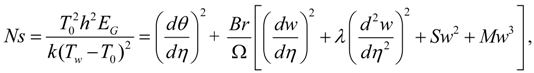
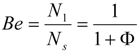
is the temperature difference parameter and Br = EcPr is the Brinkmann number. The Bejan number Be is defined as:
Entropy 15 04589 i015
where Ns = N1 + N2, Entropy 15 04589 i016 
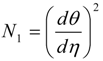
(Heat transfer Irreversibility), Entropy 15 04589 i017 
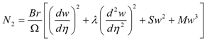
(Irreversibility due to viscous dissipation, couple stresses and porous media), Entropy 15 04589 i018(Irreversibility ratio).
From Equation (14), it is obvious that the Bejan number (Be) ranges from Entropy 15 04589 i019. While Be = 0 represents the limit case of fluid friction, couple stress and porous media dominated irreversibility, Be = 1 corresponds to the limit case of heat transfer dominated irreversibility. The contribution of both heat transfer and fluid friction to entropy production in the flow system is the same when Be = 0.5.

4. Results and Discussion

It is difficult to study the influence of all parameters involved in the present problem on the flow and thermal field along with entropy generation characteristics. Therefore, a selected set of graphical results is presented in Figure 2, Figure 3, Figure 4, Figure 5, Figure 6, Figure 7, Figure 8, Figure 9, Figure 10, Figure 11, Figure 12, Figure 13, Figure 14, Figure 15, Figure 16, Figure 17, Figure 18, Figure 19, Figure 20, Figure 21, Figure 22, Figure 23, Figure 24, Figure 25, Figure 26, Figure 27, Figure 28, Figure 29 and Figure 30 that will give a good understanding of the influence of different parameters on the velocity, temperature, entropy generation profiles, skin friction, Nusselt number and Bejan number.

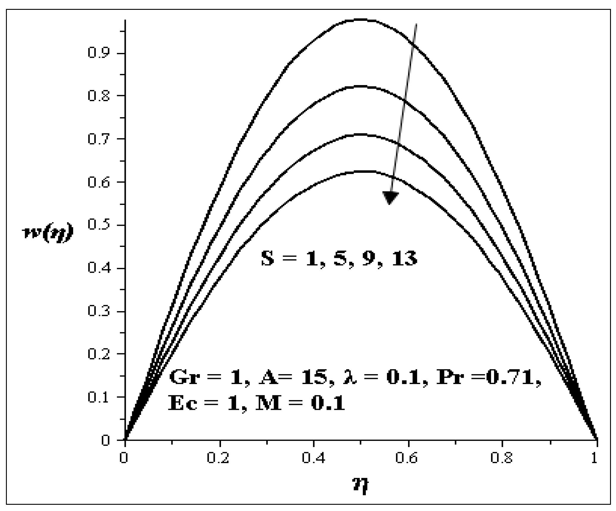
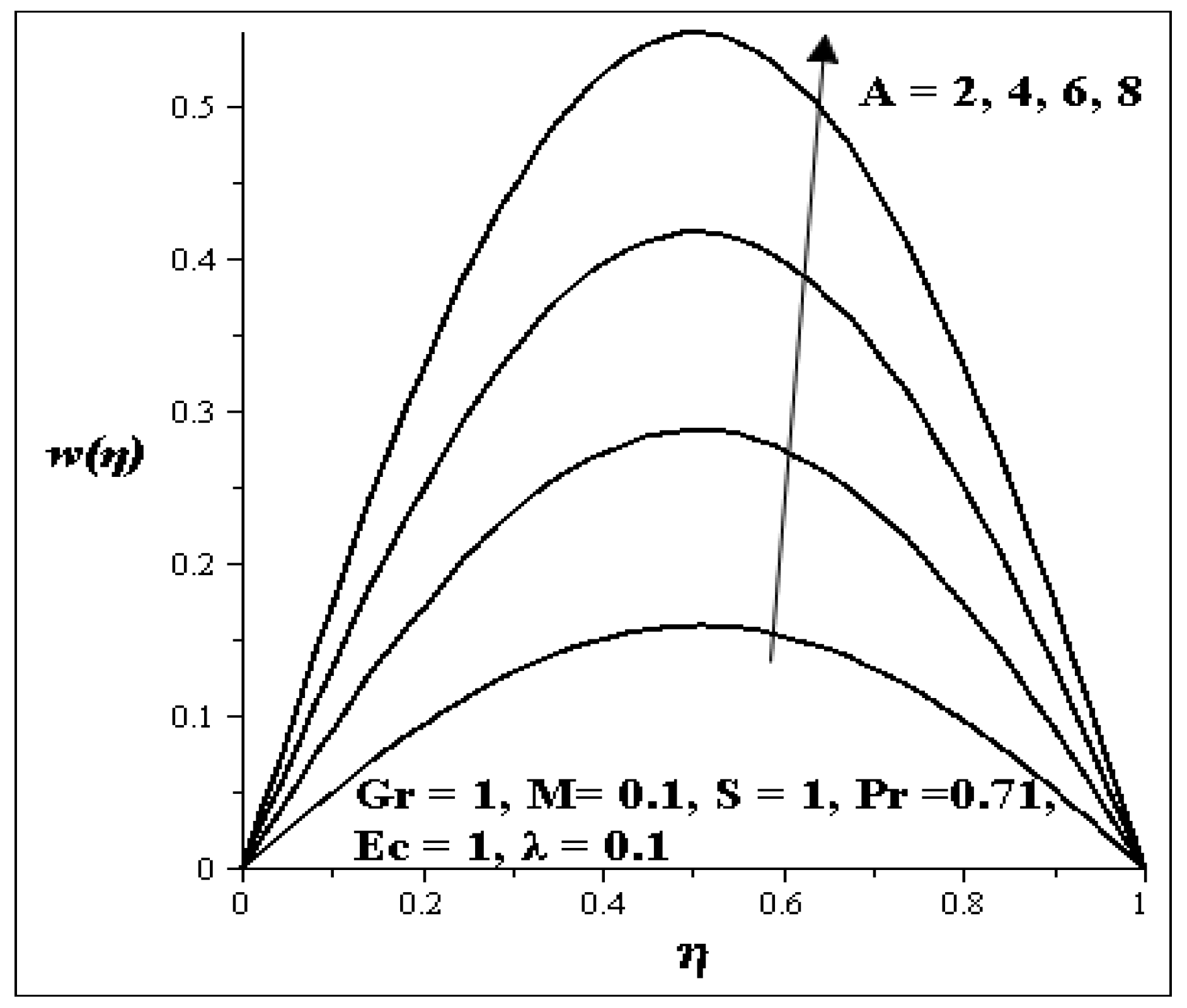
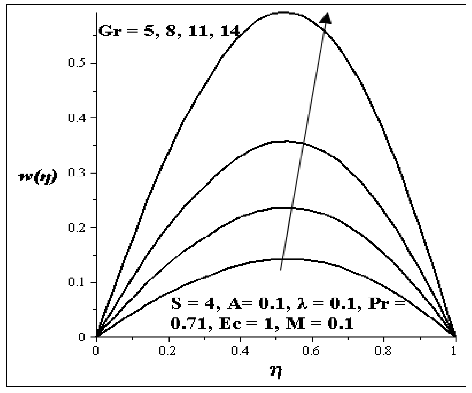
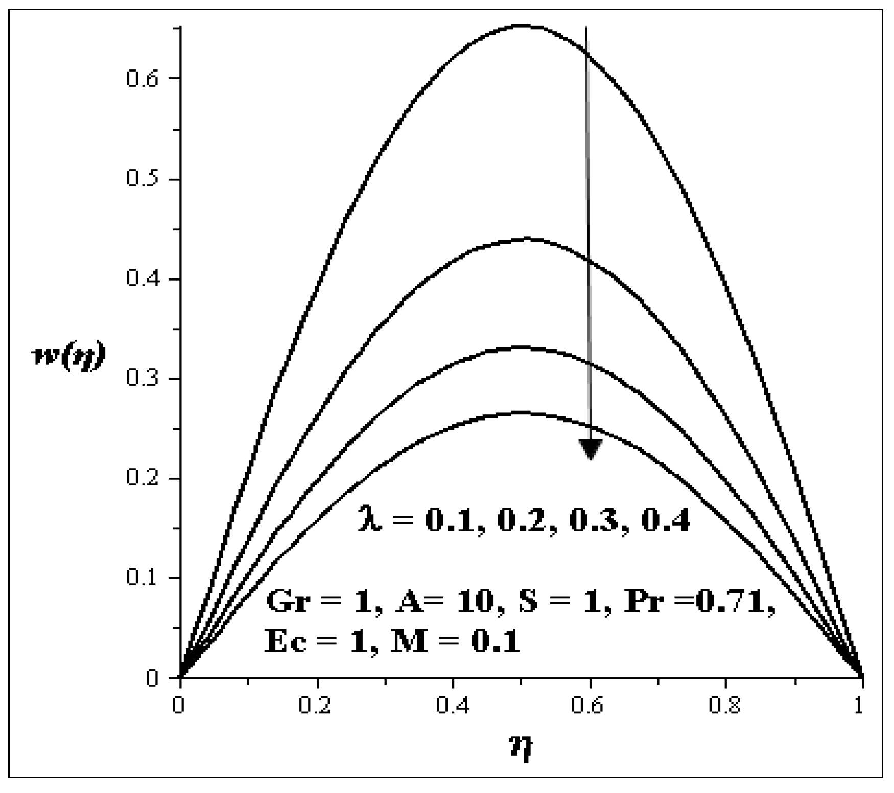
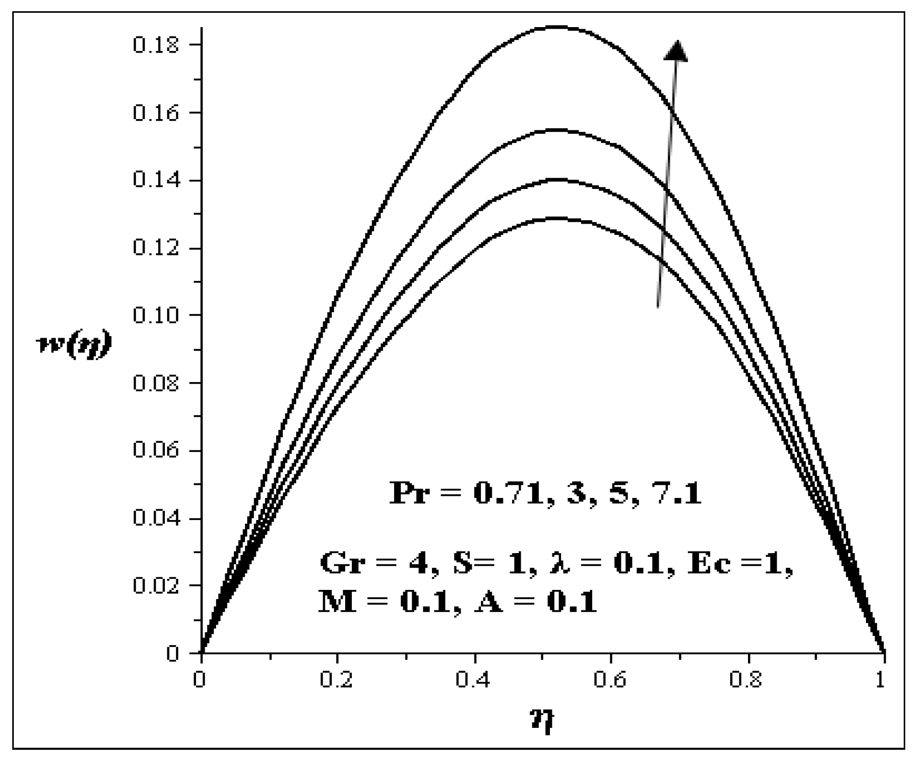
4.1. Variation of Parameters on Velocity Profile

Generally the variation effects of the parameters on velocity profile are symmetric and parabolic. The variations in the velocity profile due to the increase of the Grashof number (Gr) is shown in Figure 2. It is clear from the figure that the velocity profile increases with increasing Gr. This implies that the flow accelerates as Gr increases. Figure 3 and Figure 4 showed the effects of porous media shape factor parameter (S) and couple stress parameter (λ ) on the velocity profile. It is noticed from these figures that as S and λ are increased, respectively, the velocity of the flow is retarded while an increasing Prandtl number (Pr) in Figure 5 accelerates the velocity of the flow.
Figure 2. Effect of increasing Gr on velocity profiles.
Entropy 15 04589 g002
Figure 3. Effect of increasing S on velocity profiles.
Entropy 15 04589 g003
Figure 4. Effect of increasing λ on velocity profiles.
Entropy 15 04589 g004
Figure 5. Effect of increasing Pr on velocity profiles.
Entropy 15 04589 g005
An increase in the second order porous media resistance parameter (M) as shown in Figure 6 decreases the velocity profile of the flow. Figure 7 depicted the influence of the axial pressure gradient parameter (A) on the velocity profile. An increase in A accelerates the velocity profile of the flow.
Figure 6. Effect of increasing M on velocity profiles.
Entropy 15 04589 g006
Figure 7. Effect of increasing A on velocity profiles.
Entropy 15 04589 g007

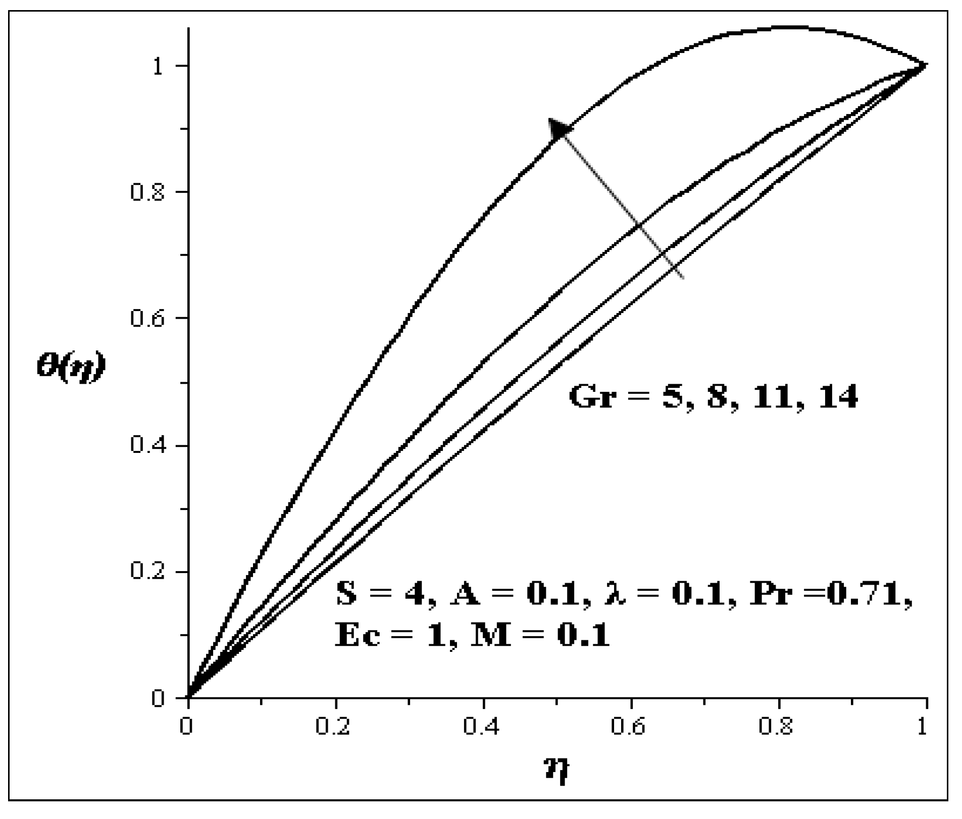
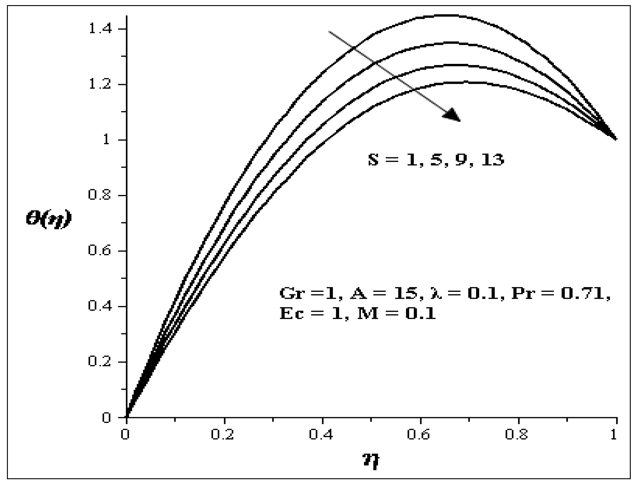
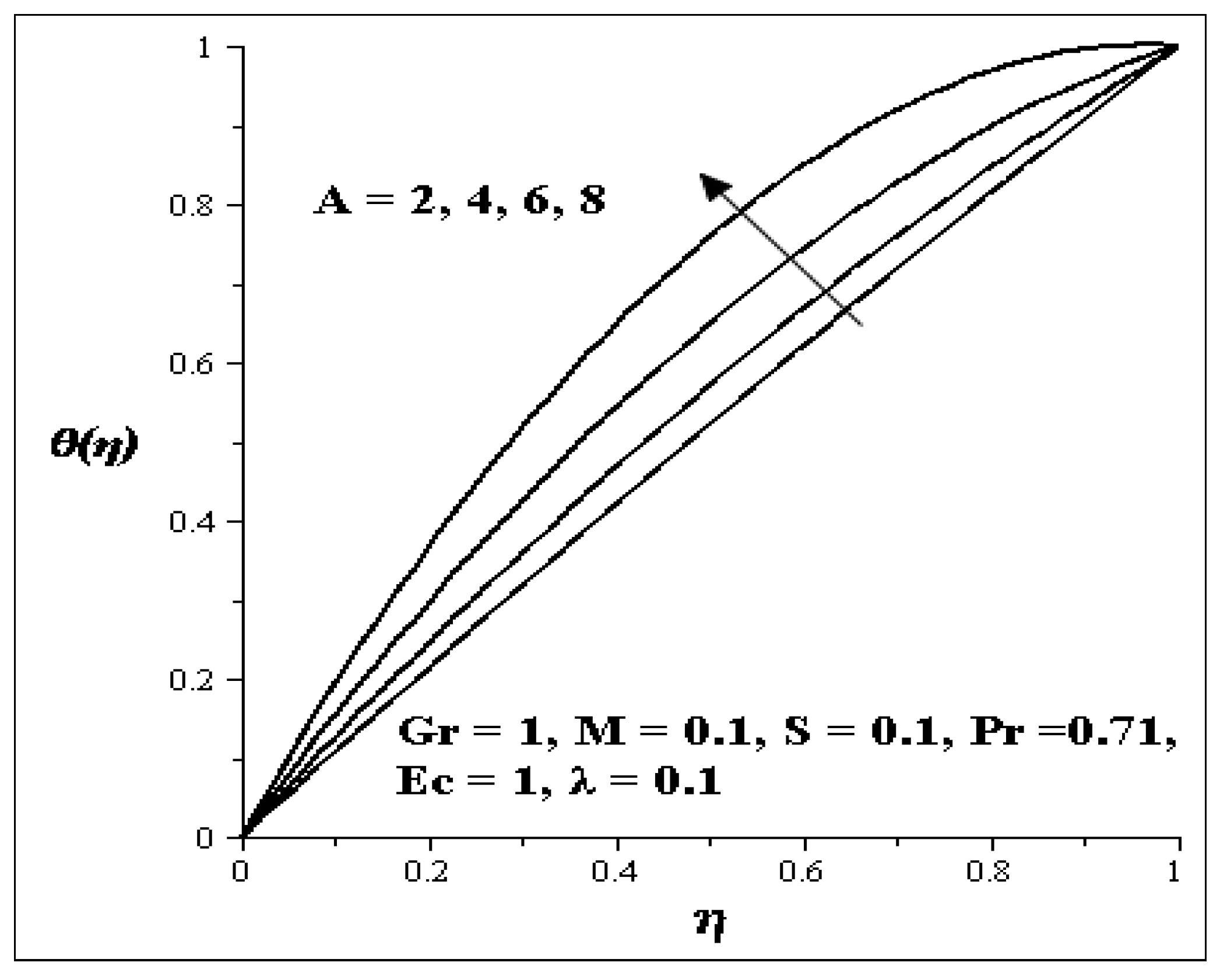
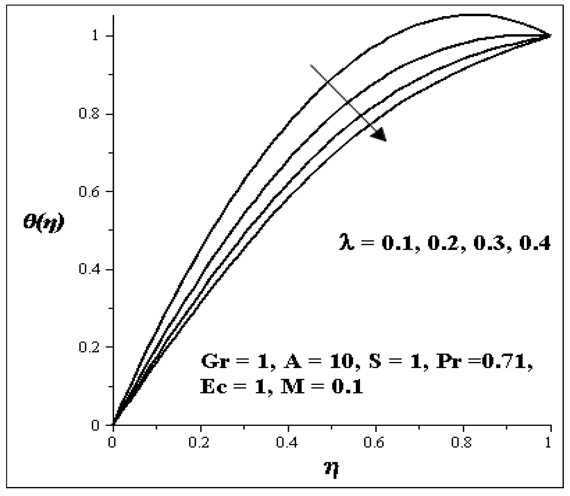
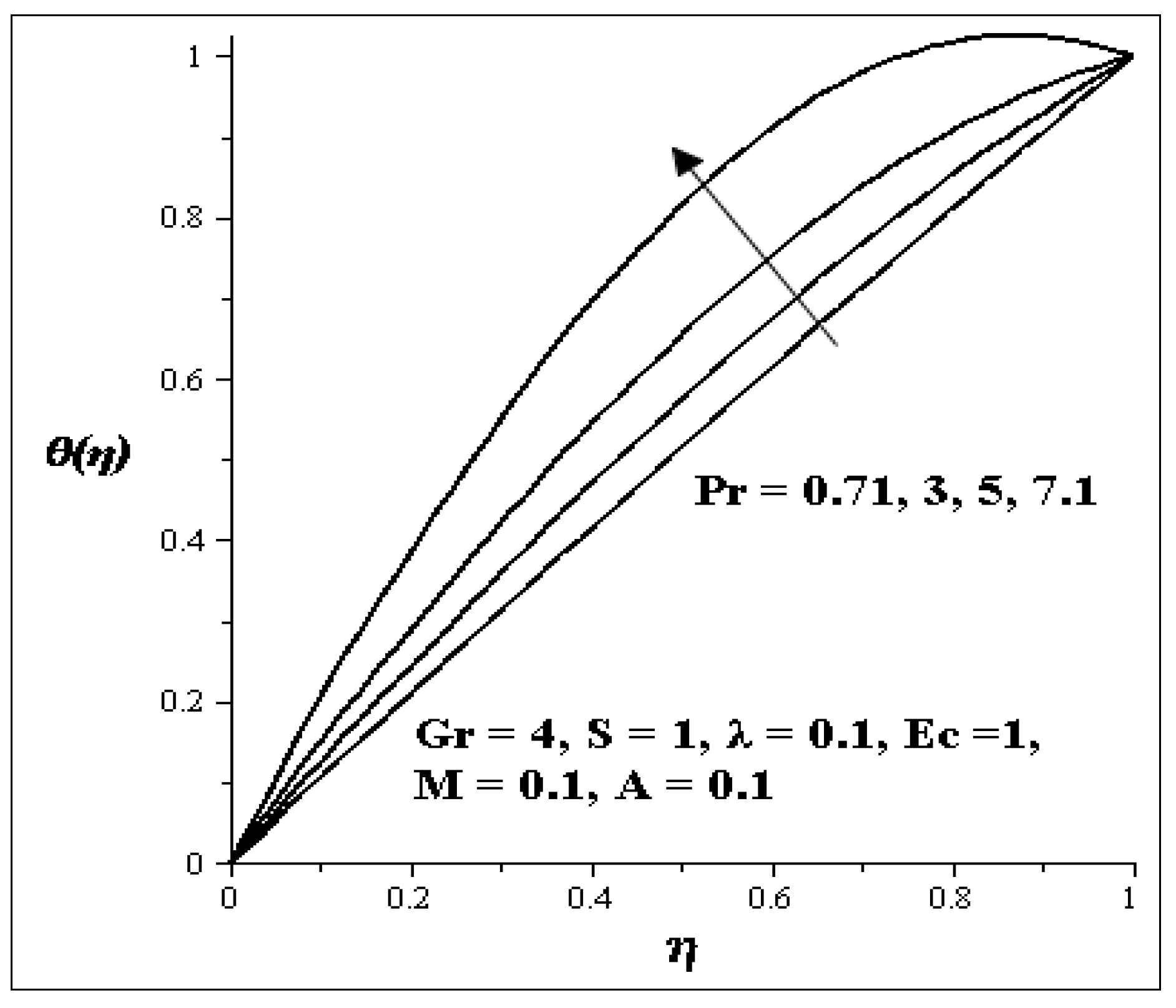
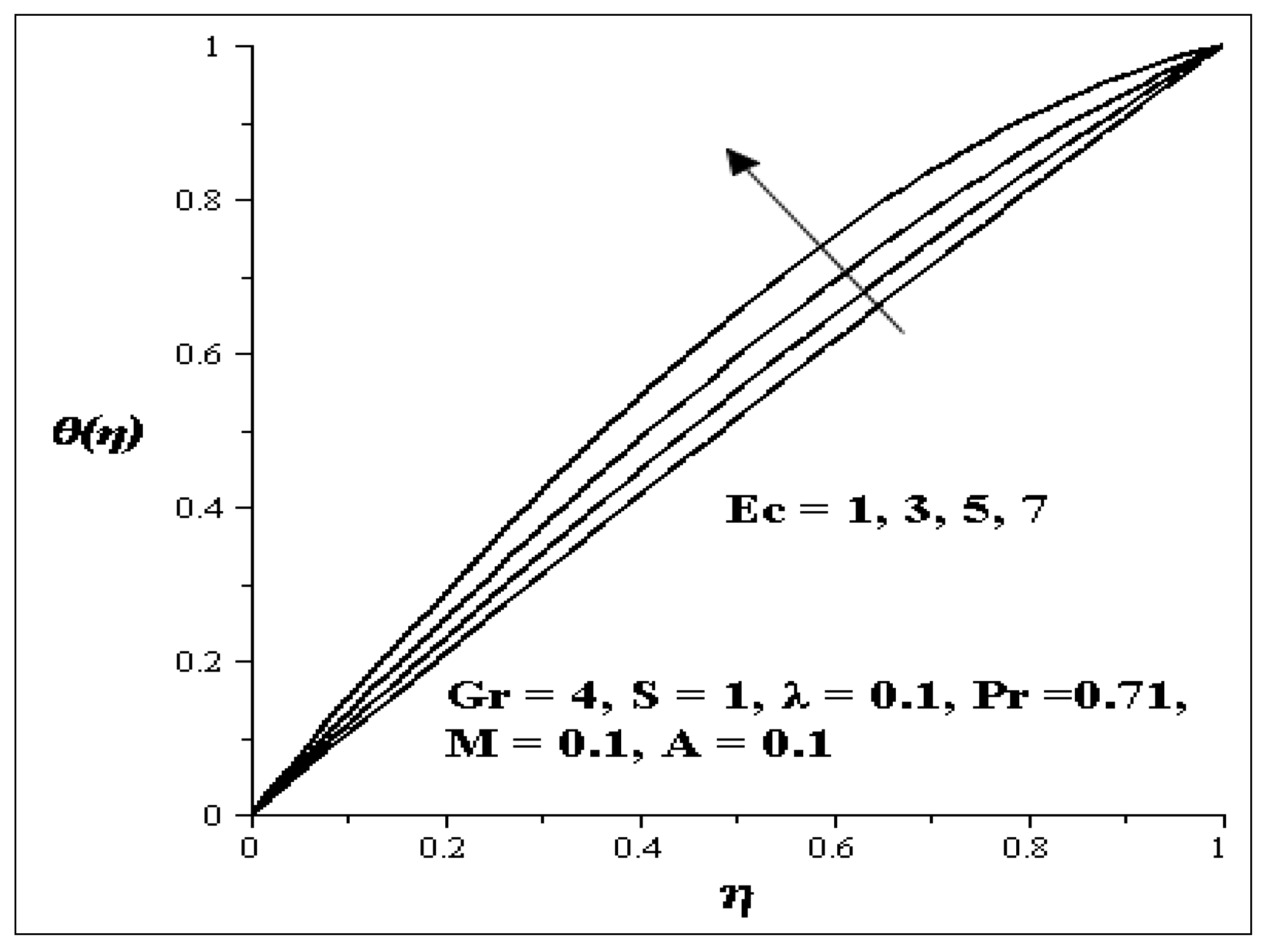
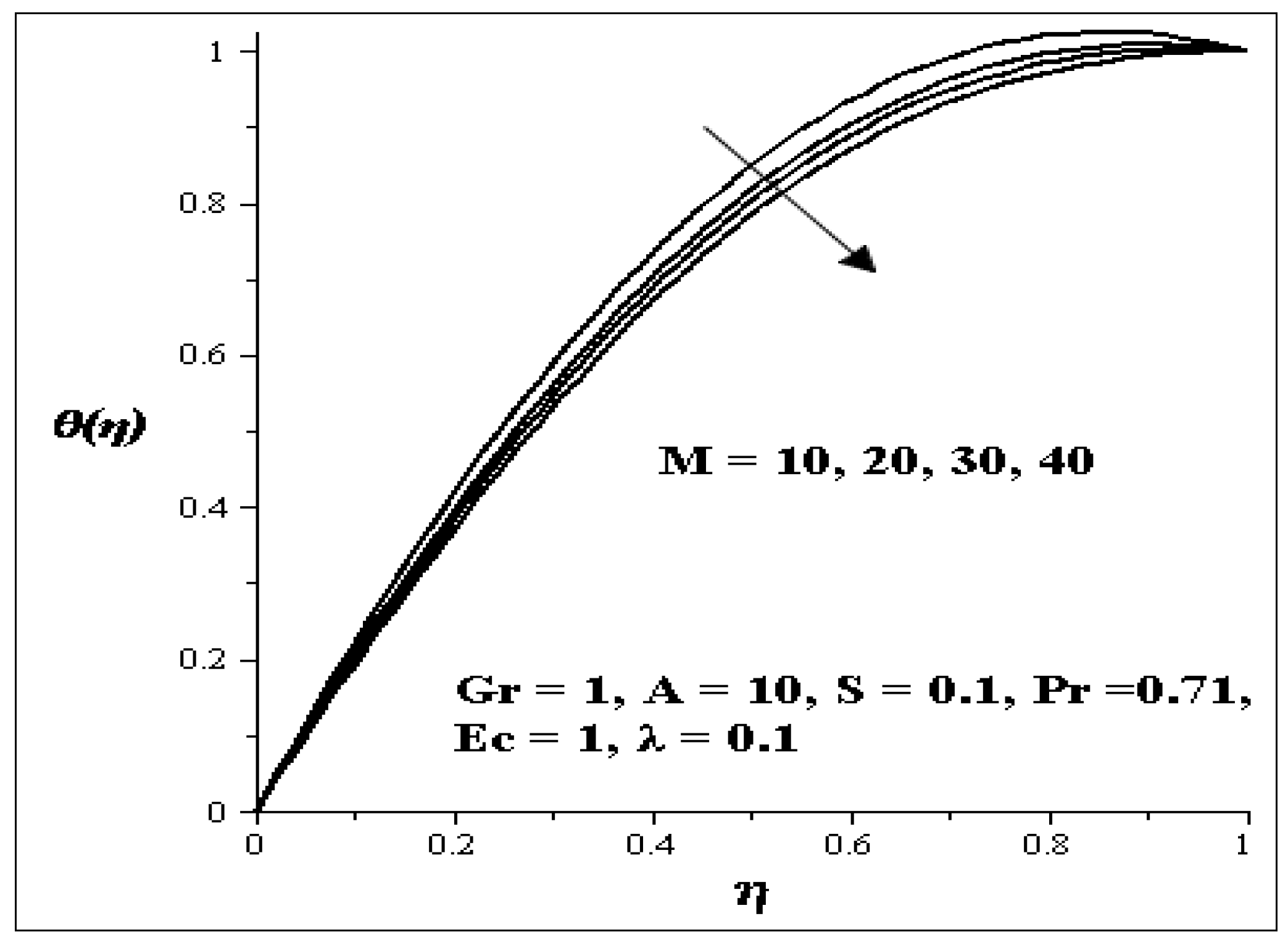
4.2. Variation of Parameters on Temperature Profile

The influences of the variation of parameters on temperature profile are presented graphically in Figure 8, Figure 9, Figure 10, Figure 11, Figure 12, Figure 13 and Figure 14. Figure 8 illustrates the effect of Gr on the temperature profile. It is noticed that as Gr increases, the temperature profile increases. The effect of S on the temperature profile is shown in Figure 9. It is observed that an increase in the porous media shape factor parameter (S) chip in to decrease the temperature. The influence of the couple stress parameter (λ ) on the temperature profile is depicted in Figure 10. It is noticed that as λ increases, the temperature profile decreases. Meanwhile the influence of each of these parameters [i.e., Prandtl number (Pr), Eckert number (Ec) and axial pressure gradient parameter (A)] are shown in Figure 11, Figure 12 and Figure 13. As each of these parameters is increasing, it is observed that the temperature of the flow increases, but an increase in the second order porous media resistance parameter (M) caused the temperature of the flow to decrease as shown in Figure 14.
Figure 8. Increasing Gr on Temperature profiles.
Entropy 15 04589 g008
Figure 9. Increasing S on Temperature profiles.
Entropy 15 04589 g009
Figure 10. Increasing λ on Temperature profiles.
Entropy 15 04589 g010
Figure 11. Increasing Pr on Temperature profiles.
Entropy 15 04589 g011
Figure 12. Increasing Ec on Temperature profiles.
Entropy 15 04589 g012
Figure 13. Increasing A on Temperature profiles.
Entropy 15 04589 g013
Figure 14. Effect of increasing M on Temperature profiles.
Entropy 15 04589 g014

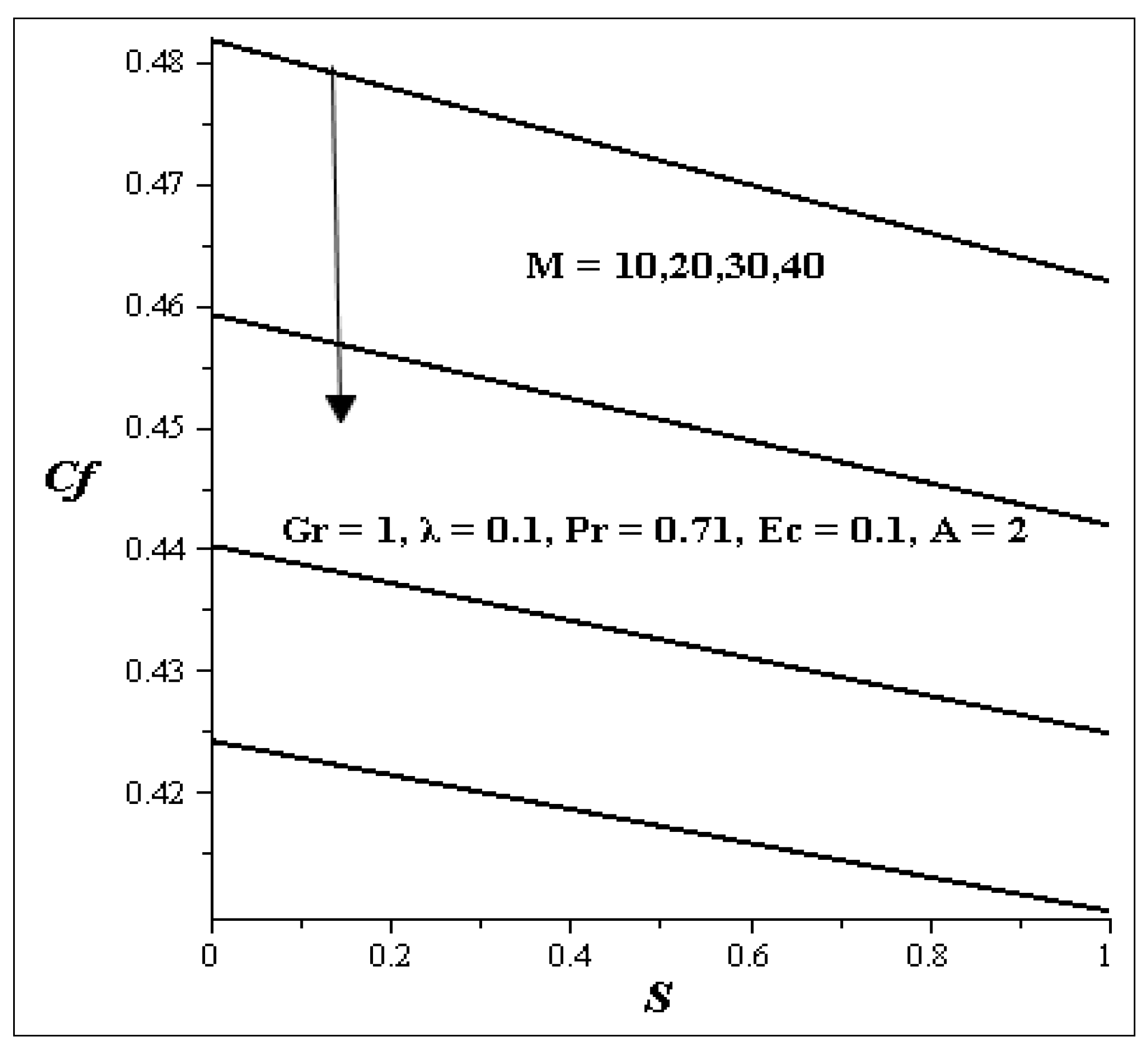
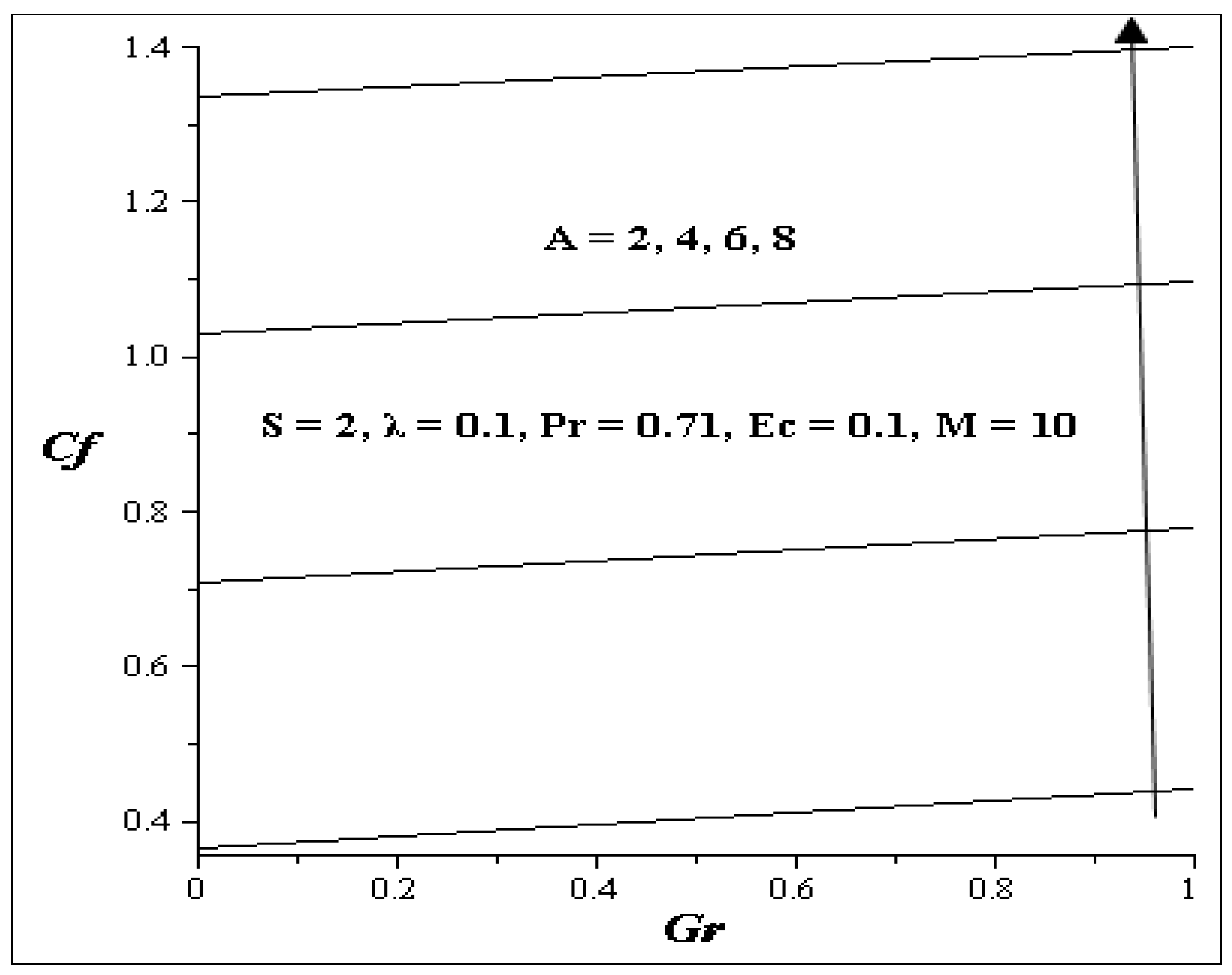
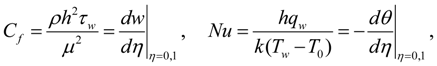
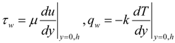
4.3. Variation of Parameters on Skin Friction

The effects of various parameters on skin friction at are shown in Figure 15 and Figure 16. Figure 15 shows skin friction for various values of M versus S. It is noticed from the figure that skin friction decreases as the values of M versus S increase, while other parameters are kept constant. Figure 16 illustrates skin friction for different values of A versus Gr. Skin friction increases as A versus Gr increases.
Figure 15. Skin friction for M verses S.
Entropy 15 04589 g015
Figure 16. Skin friction for A verses Gr.
Entropy 15 04589 g016

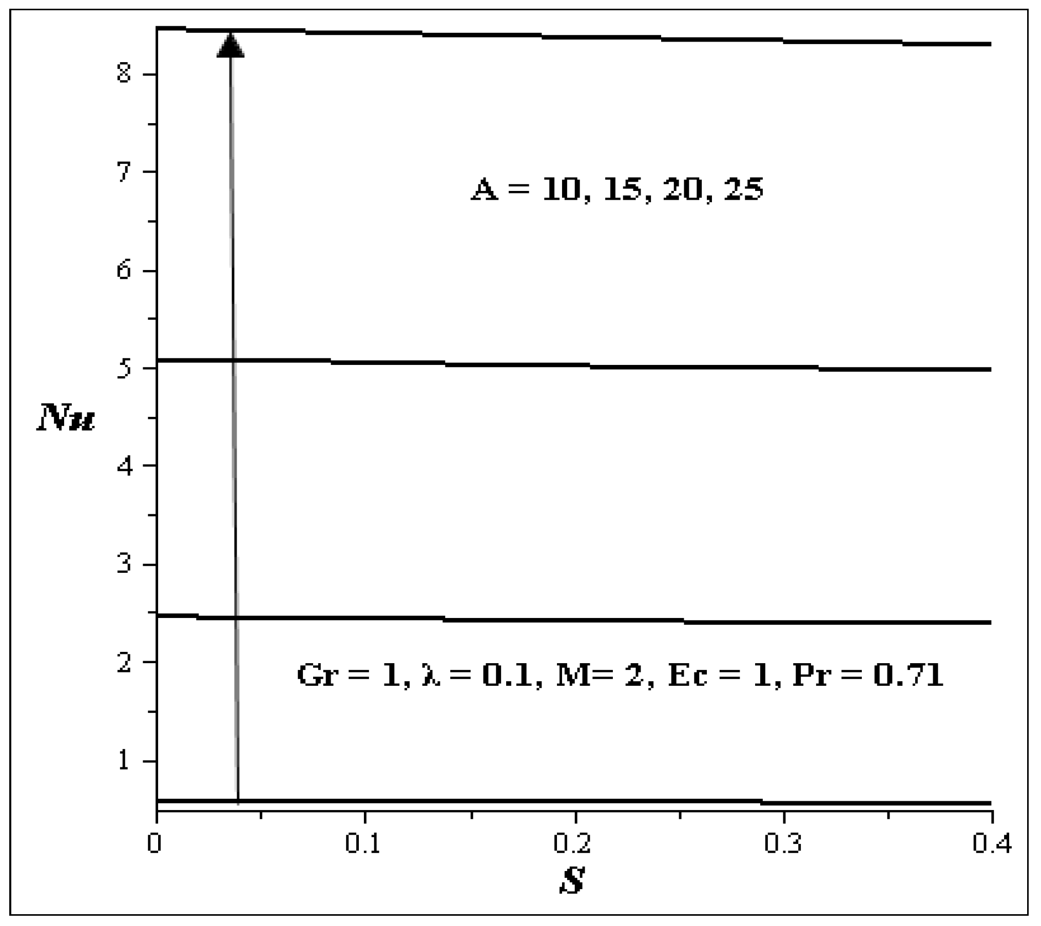
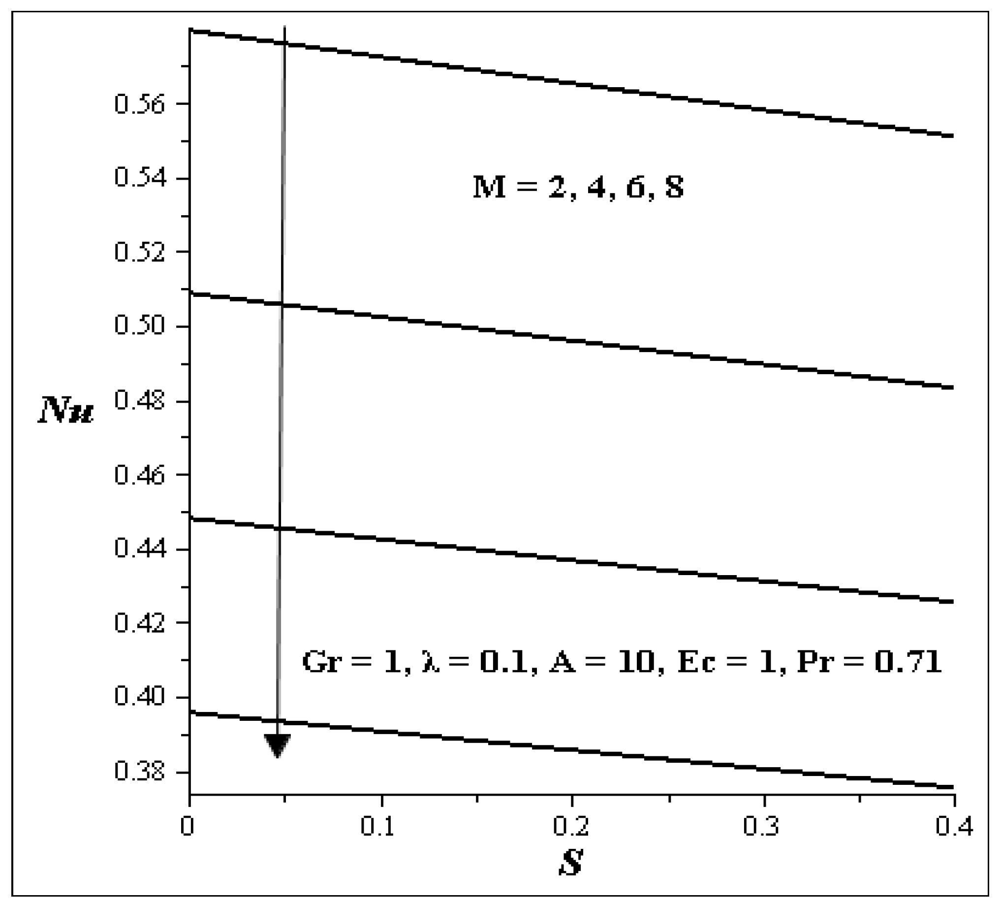
4.4. Variation of Parameters on Nusselt Number

The various effects of some parameters on Nusselt number are depicted in Figure 17 and Figure 18. Figure 17 illustrates the effects of Nusselt number (Nu) with increase in A versus S. As A and S are increasing while others are kept constant, it is noticed that the Nusselt number increases. Figure 18 shows the effect of M verses S. As M verses S is increasing, it is observed that Nusselt number decreases.
Figure 17. Nusselt number for A verses S.
Entropy 15 04589 g017
Figure 18. Nusselt number for M verses S.
Entropy 15 04589 g018

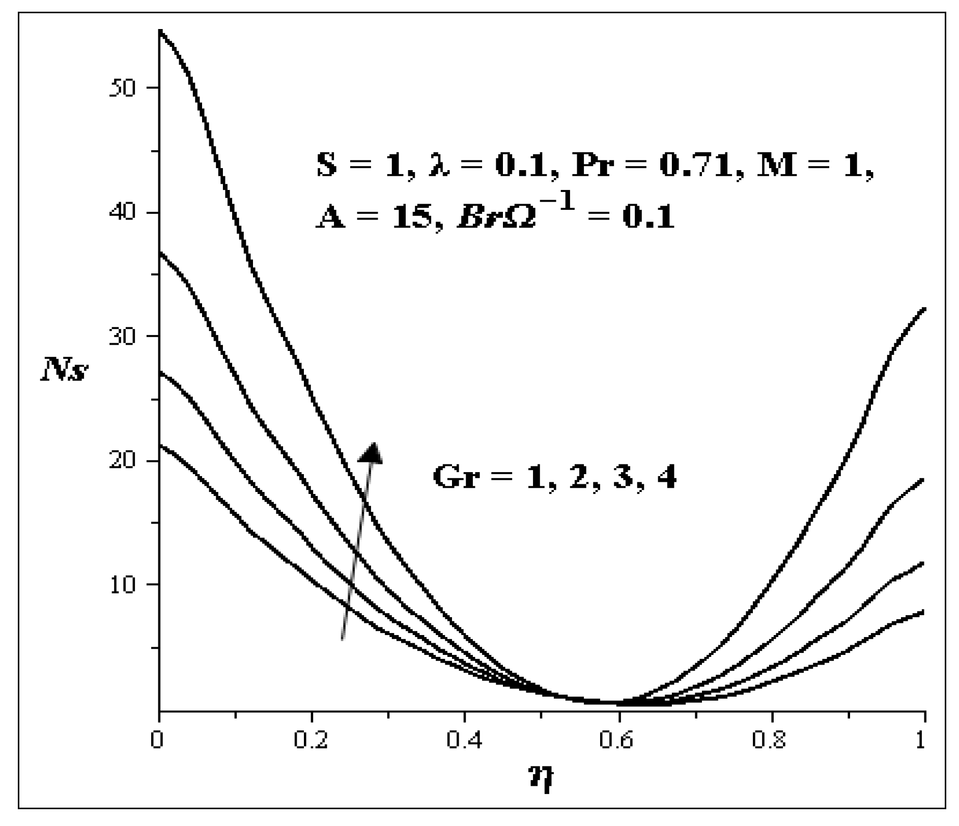
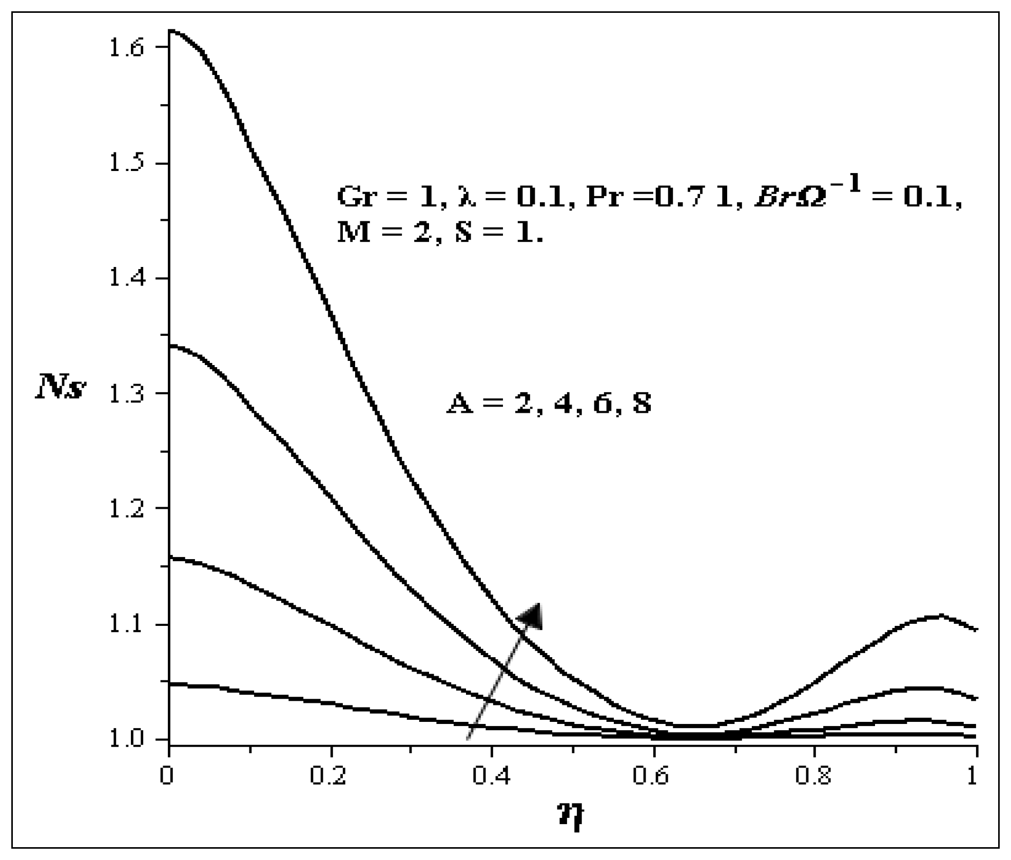
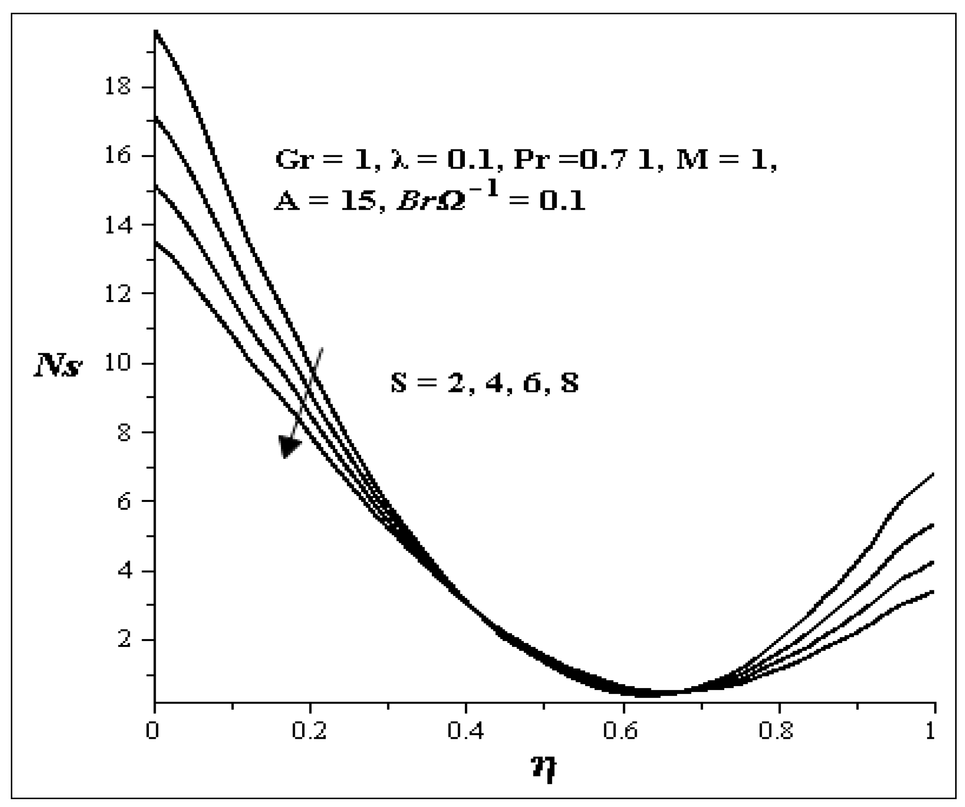
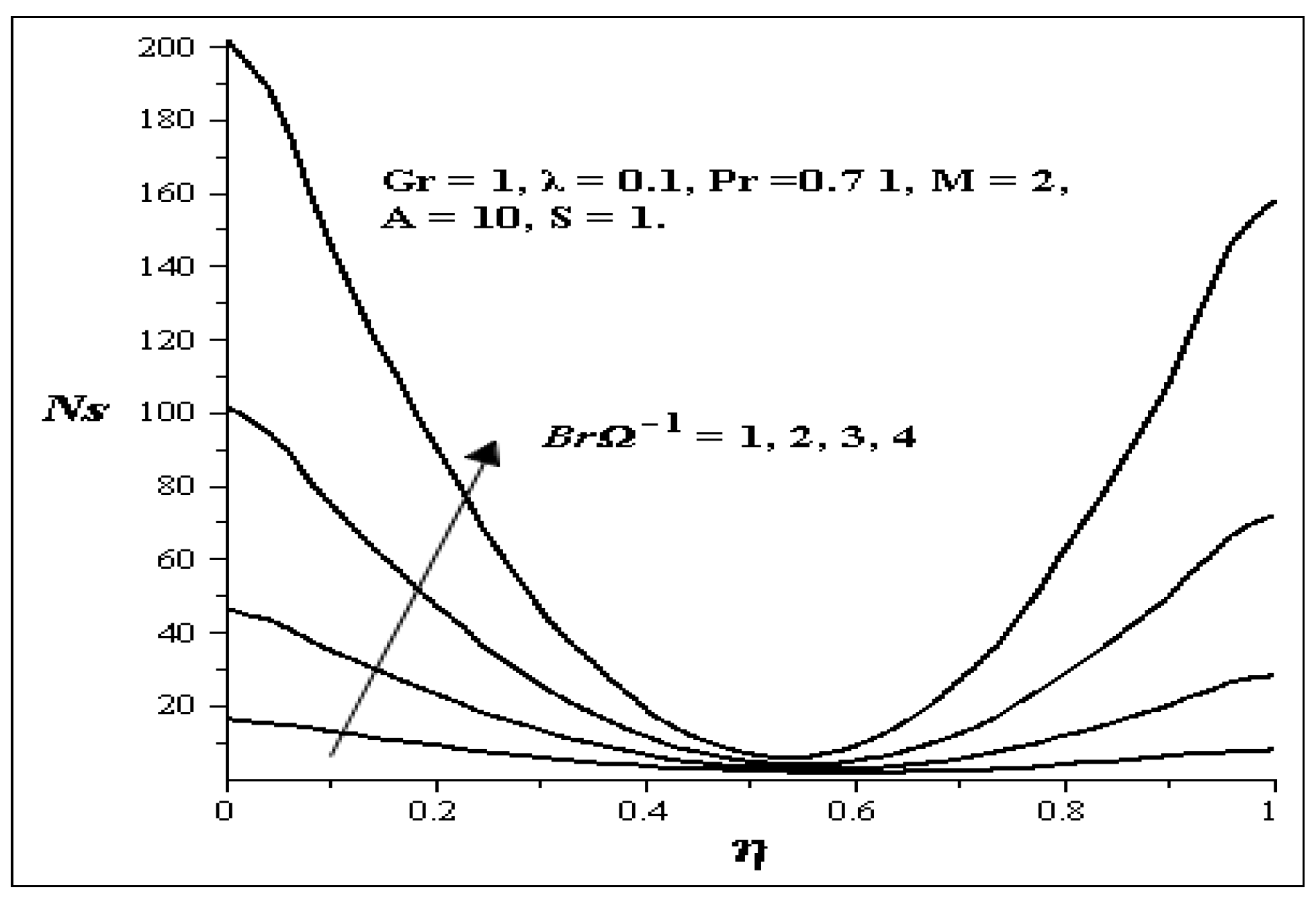
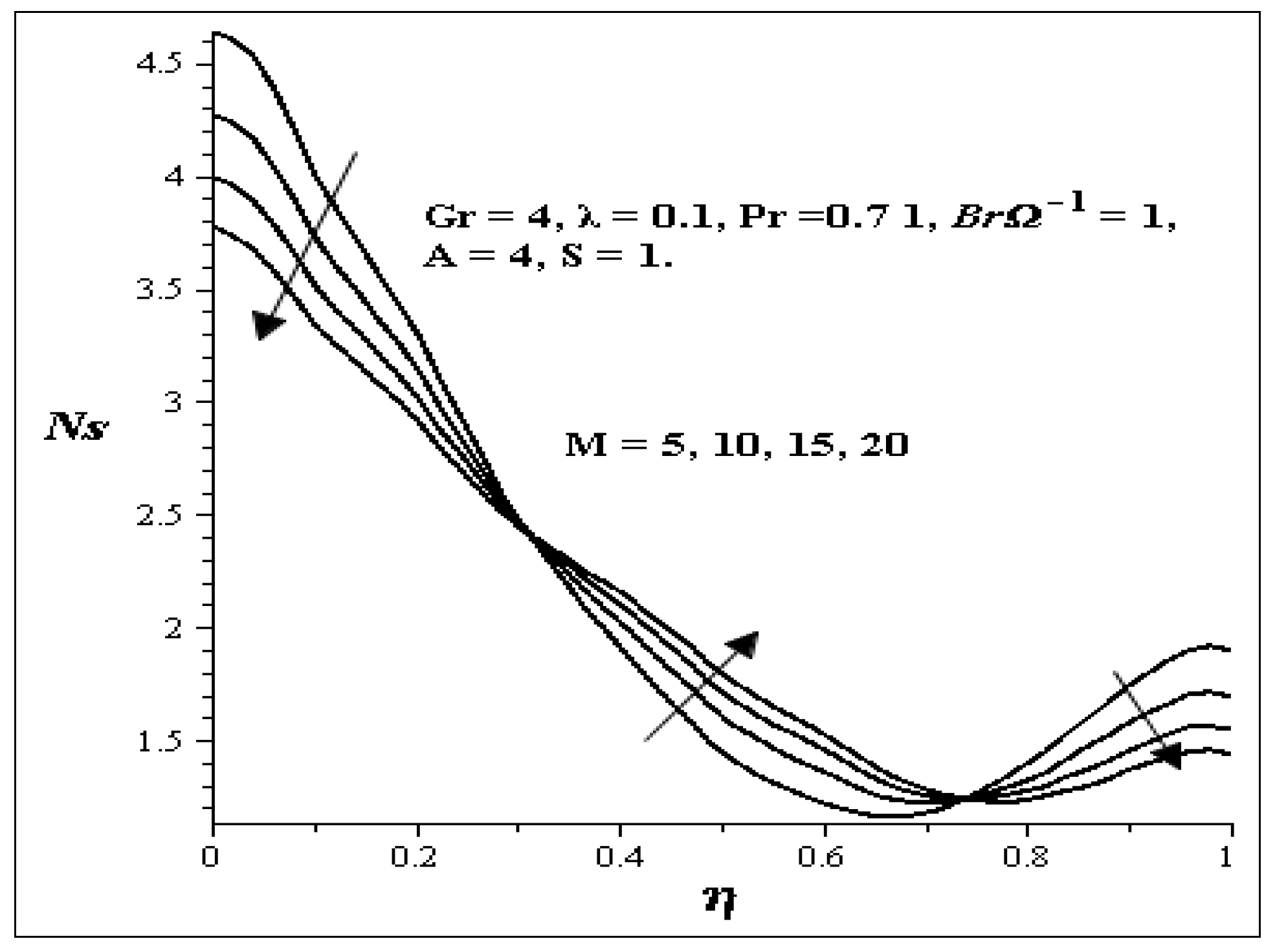
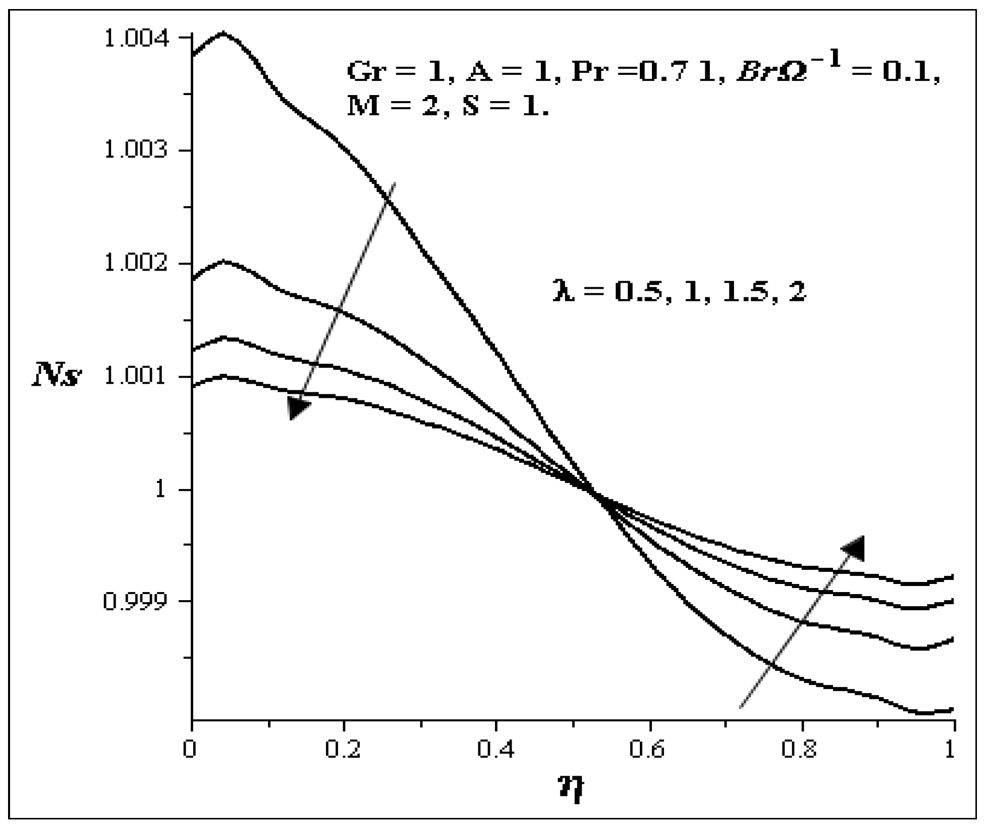
4.4. Effect of Various Parameters on Entropy Generation Profiles

The entropy generation profiles for different values of key parameters are described in Figure 19, Figure 20, Figure 21, Figure 22, Figure 23, Figure 24 and Figure 25. Figure 19 shows that as Gr increases, the entropy generation at both walls also increases while all other parameters are kept constant. Figure 20 illustrates the increase in S. As S increases, the entropy generation at both walls decreases but between η = 0.4 and η = 0.7, it seems there is no effect on the entropy generation profile. Figure 21 shows the effects of Br−1. With an increase in Br−1 while all other parameters are kept constant, there exit an increase in the entropy generation profile at both walls and it is symmetric, but at η = 0.5, there is no change in the entropy generation. Figure 22 shows the effect of M on the entropy generation profile. An increase in M causes a decrease in the entropy generation at both walls, but between η = 0.3 and η = 0.75, an increase in entropy generation profile is noticed. Figure 23 shows the effect of A on the entropy generation profile. As A is increasing, large increases in the entropy generation at the lower wall are noticed while little increase is noticed on the upper wall. Increases in λ as shown in Figure 24 decrease the entropy generation profile at the lower wall and increase the entropy generation profile at the upper wall.
Figure 19. Effect of increasing Gr on Ns.
Entropy 15 04589 g019
Figure 20. Effect of increasing S on Ns.
Entropy 15 04589 g020
Figure 21. Effect of increasing Br−1 on Ns.
Entropy 15 04589 g021
Figure 22. Effect of increasing M on Ns.
Entropy 15 04589 g022
Figure 23. Effect of increasing A on Ns.
Entropy 15 04589 g023
Figure 24. Effect of increasing λ on entropy Ns.
Entropy 15 04589 g024

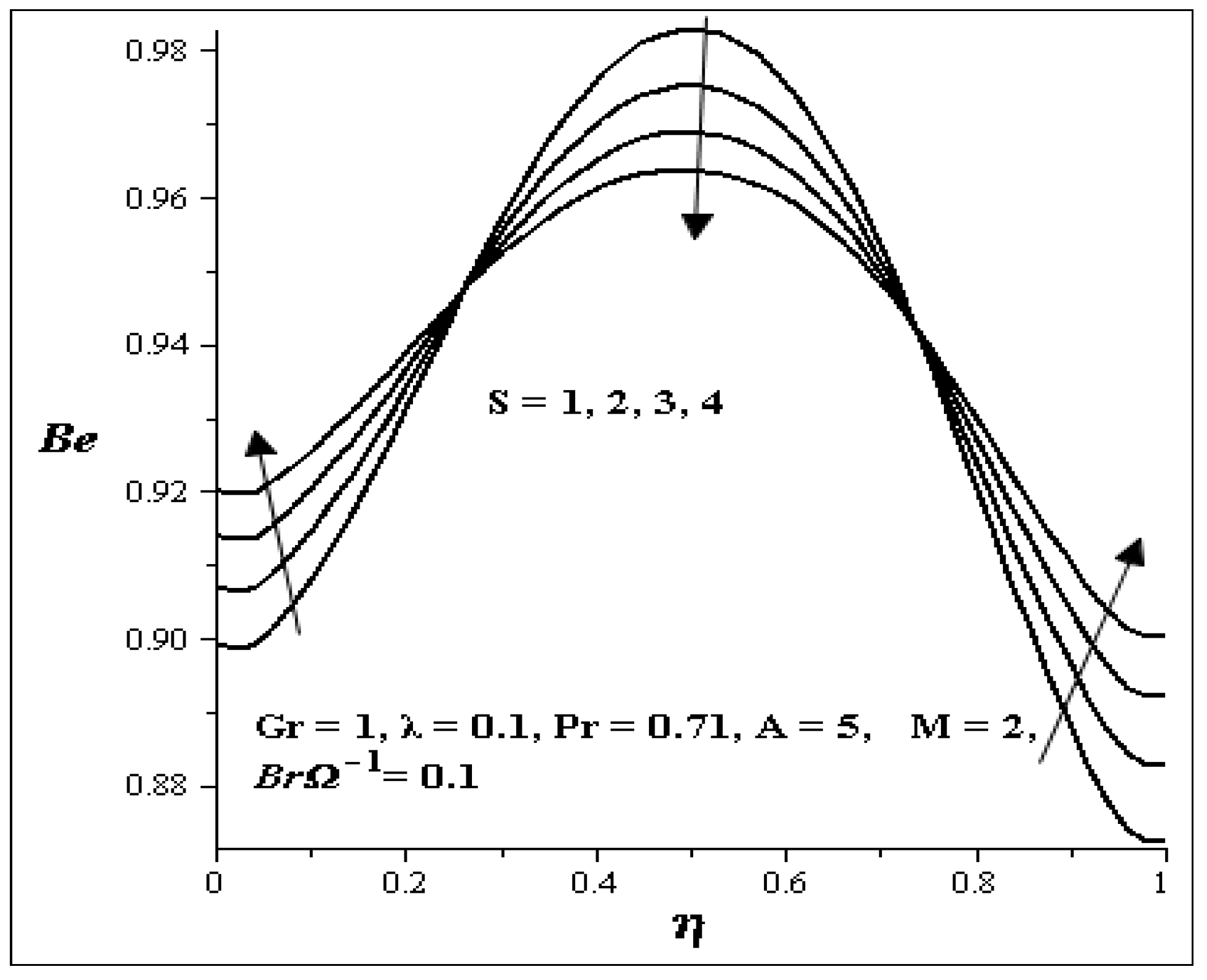
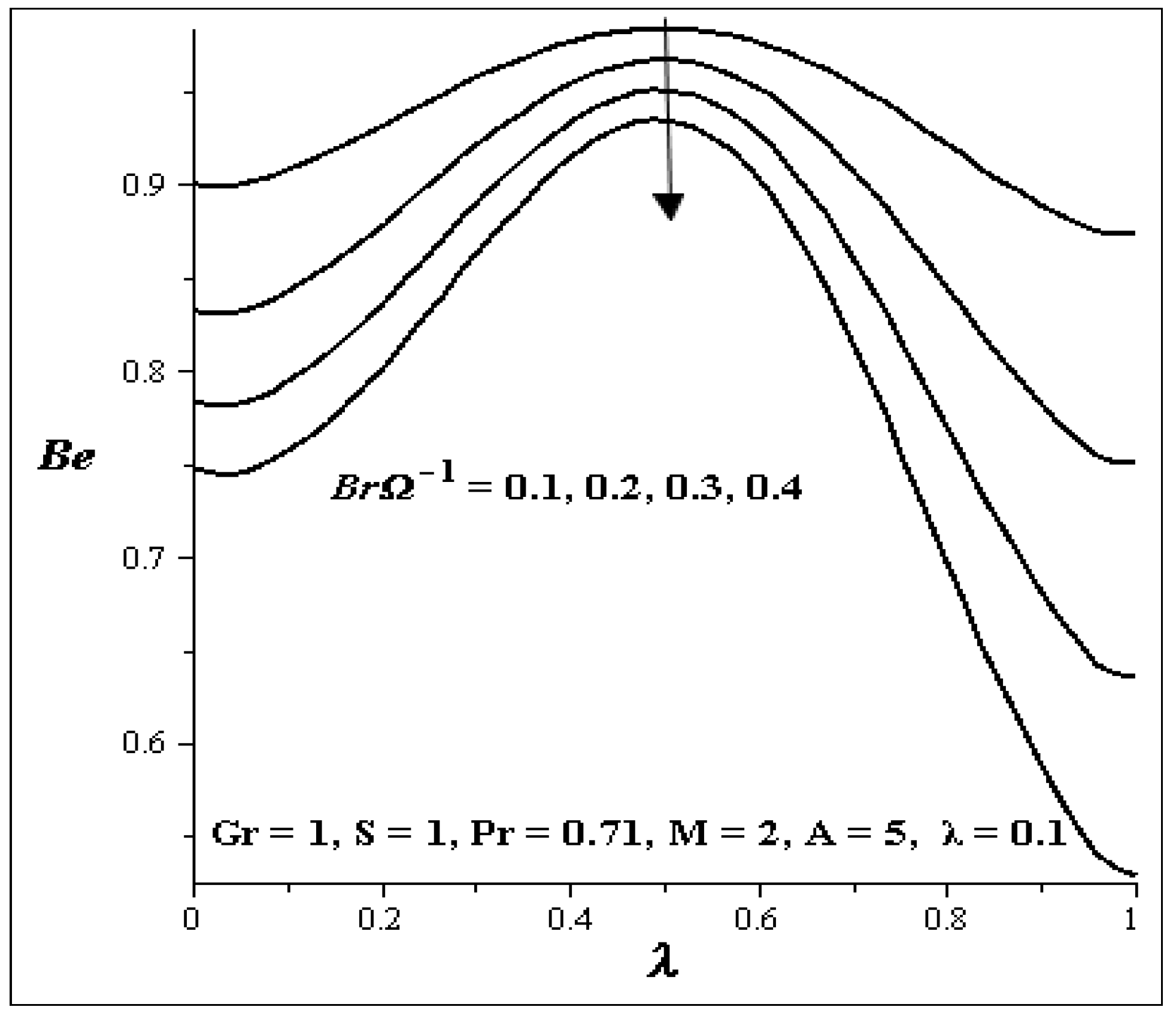
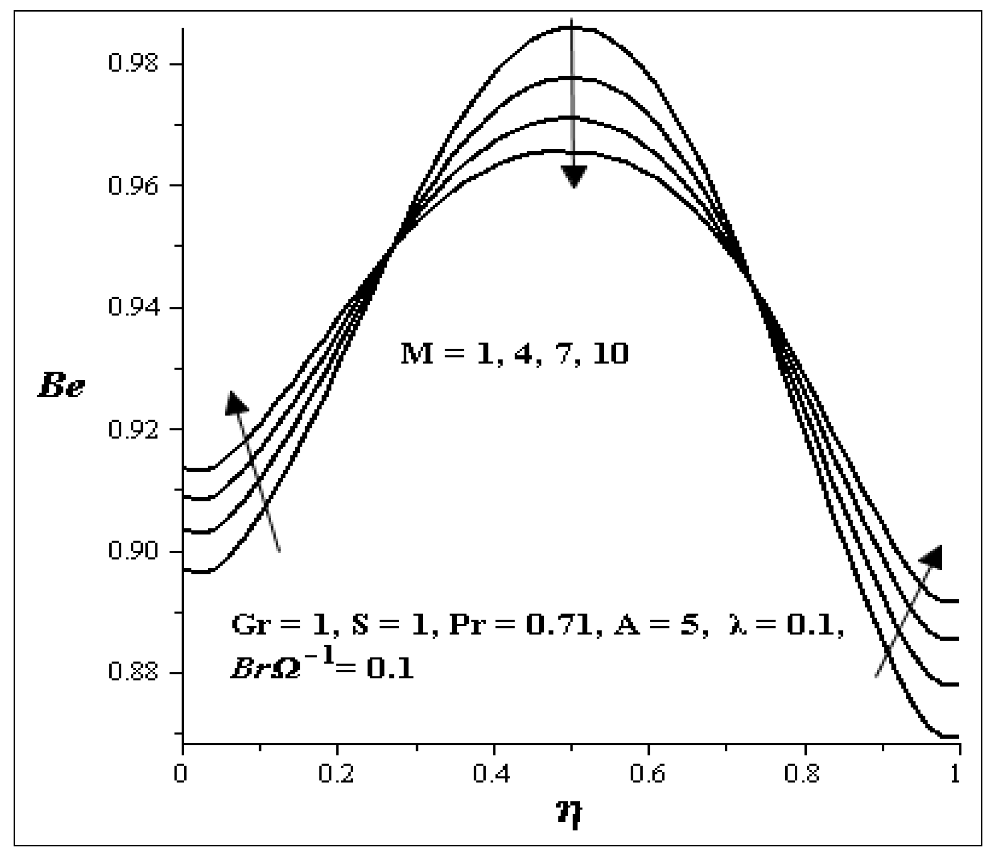
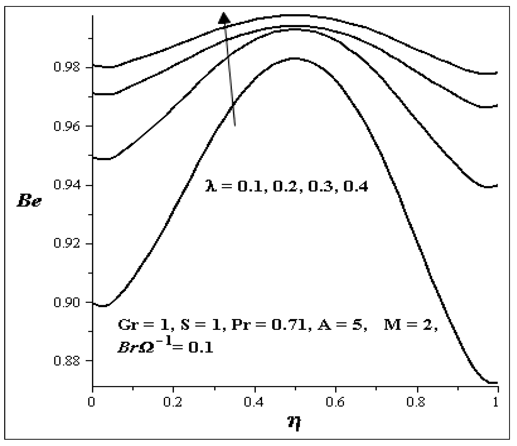
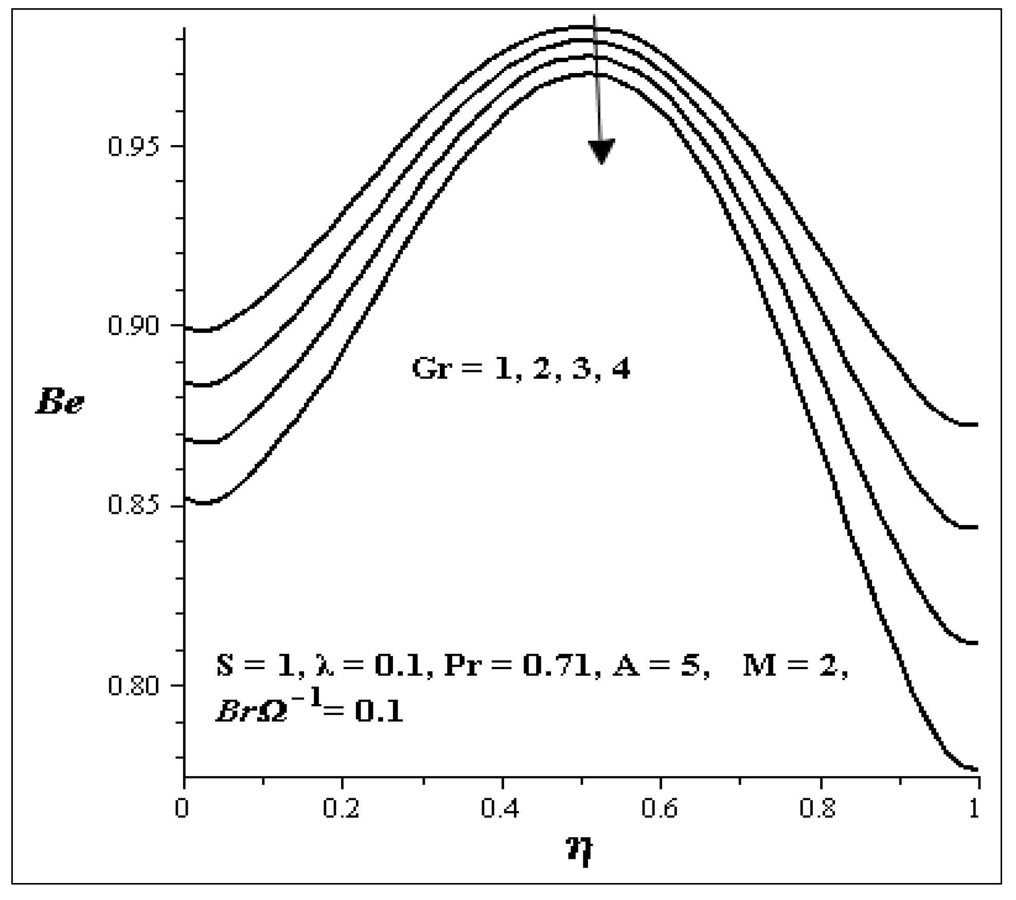
4.5. Effect of Different Parameters on Bejan Number

The influences of the key parameters on the Bejan number are illustrated in Figure 25, Figure 26, Figure 27, Figure 28, Figure 29 and Figure 30. Generally, we see that the graphs are parabolic in nature. The influence of S is shown in Figure 25. As S increases, the Bejan number at both walls increases but at the center of the channel, it decreases. Figure 26 shows uniform decrease in the Bejan number as Gr increases. Figure 27 and Figure 28 show the effects of A and Br−1 on the Bejan number. An increase in each of these parameters decreases the Bejan number across the flow uniformly. The influence of M on the Bejan number is shown in Figure 29. It is noticed that the Bejan number decrease between η = 0.3 and η = 0.7 but increases at the both walls as M increases. Figure 30 shows that increase in λ, increase the Bejan number across the flow.
Figure 25. Effect of increasing S on Be.
Entropy 15 04589 g025
Figure 26. Effect of increasing Gr on Be.
Entropy 15 04589 g026
Figure 27. Effect of increasing A on Be.
Entropy 15 04589 g027
Figure 28. Effect of increasing Br−1 on Be.
Entropy 15 04589 g028
Figure 29. Effect of increasing M on Be.
Entropy 15 04589 g029
Figure 30. Effect of increasing λ on Be.
Entropy 15 04589 g030

5. Conclusions

We analyze the entropy generation in couple stress fluid flows through a vertical channel filled with saturated porous media. The nonlinear governing equations are solved numerically using shooting methods together with a Runge-Kutta Fehlberg integration scheme. We discussed the behaviours of the velocity profile, temperature profile, skin friction, Nusselt number, entropy generation profile and Bejan number for different value of parameters in the governing equations. From the discussion, we may conclude the following:
  • The velocity profiles in general are parabolic in nature. Increases in Gr, Pr and A increase the velocity profile, while increases in M, S and λ decrease the velocity profile.
  • An increase in Gr, Pr, Ec and A increases the temperature profile, while increases in S, M and λ decrease the temperature profile.
  • An increase in M verses S decreases the skin friction, while an increase in A versus Gr increases the skin friction.
  • The Nusselt number increases with increasing A versus S, while it decreases with an increase in M versus S.
  • Entropy generation increases with increases in Gr, Br−1 and A, while it decreases with an increase in S. As M increases, its decreases at both walls, but increases in the centre of the channel.
  • Increases in Gr, A and Br−1 decrease the Bejan number across the flow, while an increase in λ increases the Bejan number across the flow. Increases in M and S; increase the Bejan number at both walls, but at the centre of the channel, the Bejan number decreases.

Conflicts of Interest

The authors declare no conflict of interest.

References

  1. Stokes, V.K. Couple stresses in fluid. Phys. Fluids 1966, 9, 1709–1715. [Google Scholar] [CrossRef]
  2. Stokes, V.K. Theories of Fluids with Microstructure: An Introduction; Springer: New York, NY, USA, 1984. [Google Scholar]
  3. Srinivasacharya, D.; Srikanth, D. Effect of couple stresses on the flow in a constricted annulus. Arch. Appl. Mech. 2008, 78, 251–257. [Google Scholar] [CrossRef]
  4. Nield, D.A.; Bejan, A. Convection in Porous Media; Springer: New York, NY, USA, 2006. [Google Scholar]
  5. Postelnicu, A. Influence of a magnetic field on heat and mass transfer by natural convection from vertical surfaces in porous media considering Soret and Dufour effects. Int. J. Heat Mass Trans. 2004, 47, 1467–1475. [Google Scholar] [CrossRef]
  6. Makinde, O.D.; Mhone, P.Y. On temporal stability analysis for hydromagnetic flow in a channel filled with a saturated porous medium. Flow Turbul. Combust. 2009, 83, 21–32. [Google Scholar] [CrossRef]
  7. Makinde, O.D.; Aziz, A. MHD mixed convection from a vertical plate embedded in a porous medium with a convective boundary condition. Int. J. Therm. Sci. 2010, 49, 1813–1820. [Google Scholar] [CrossRef]
  8. Makinde, O.D.; Chinyoka, T.; Rundora, L. Unsteady flow of a reactive variable viscosity non-Newtonian fluid through a porous saturated medium with asymmetric convective boundary conditions. Comp. Math. Appl. 2011, 62, 3343–3352. [Google Scholar] [CrossRef]
  9. Bejan, A. Second-law analysis in heat transfer and thermal design. Adv. Heat Trans. 1982, 15, 1–58. [Google Scholar]
  10. Bejan, A. Entropy Generation Minimization; CRC: Boca Raton, FL, USA, 1996. [Google Scholar]
  11. Wood, L.C. Thermodynamics of Fluid Systems; Oxford University Press: Oxford, UK, 1975. [Google Scholar]
  12. Ozkol, I.; Komurgoz, G.; Arikoglu, A. Entropy generation in the laminar natural convection from a constant temperature vertical plate in an infinite fluid. J. Power Energy 2007, 221, 609–616. [Google Scholar] [CrossRef]
  13. Mahmud, S.; Fraser, R.A. Mixed convection-radiation interaction in a vertical porous channel: Entropy generation. Energy 2003, 28, 1557–1577. [Google Scholar] [CrossRef]
  14. Tasnim, S.M.; Mahmud, S.; Mamum, M.A.H. Entropy generation in a porous channel with hydromagetic effect. Int. J. Exergy 2002, 3, 300–308. [Google Scholar] [CrossRef]
  15. Chauhan, D.S.; Kumar, V. Heat transfer and entropy generation during compressible fluid flow in a channel partially filled with porous medium. Int. J. Energy Tech. 2011, 3, 1–10. [Google Scholar]
  16. Eegunjobi, A.S.; Makinde, O.D. Combined effect of buoyancy force and Navier slip on entropy generation in a vertical porous channel. Entropy 2012, 33, 692–698. [Google Scholar] [CrossRef]
  17. Chen, S.; Liu, Z.H.; Bao, S.; Zheng, C.G. Natural convection and entropy generation in a vertically concentric annular space. Int. J. Therm. Sci. 2010, 49, 2439–2452. [Google Scholar] [CrossRef]
  18. Chen, S. Entropy generation of double-diffusive convection in the presence of rotation. Appl. Math. Comput. 2011, 217, 8575–8597. [Google Scholar] [CrossRef]
  19. Cebeci, T.; Bradshaw, P. Physical and Computational Aspects of Convective Heat Transfer; Springer: New York, NY, USA, 1988. [Google Scholar]

