Exergetic and Parametric Study of a Solar Aided Coal-Fired Power Plant

Abstract
:1. Introduction
2. System Descriptions
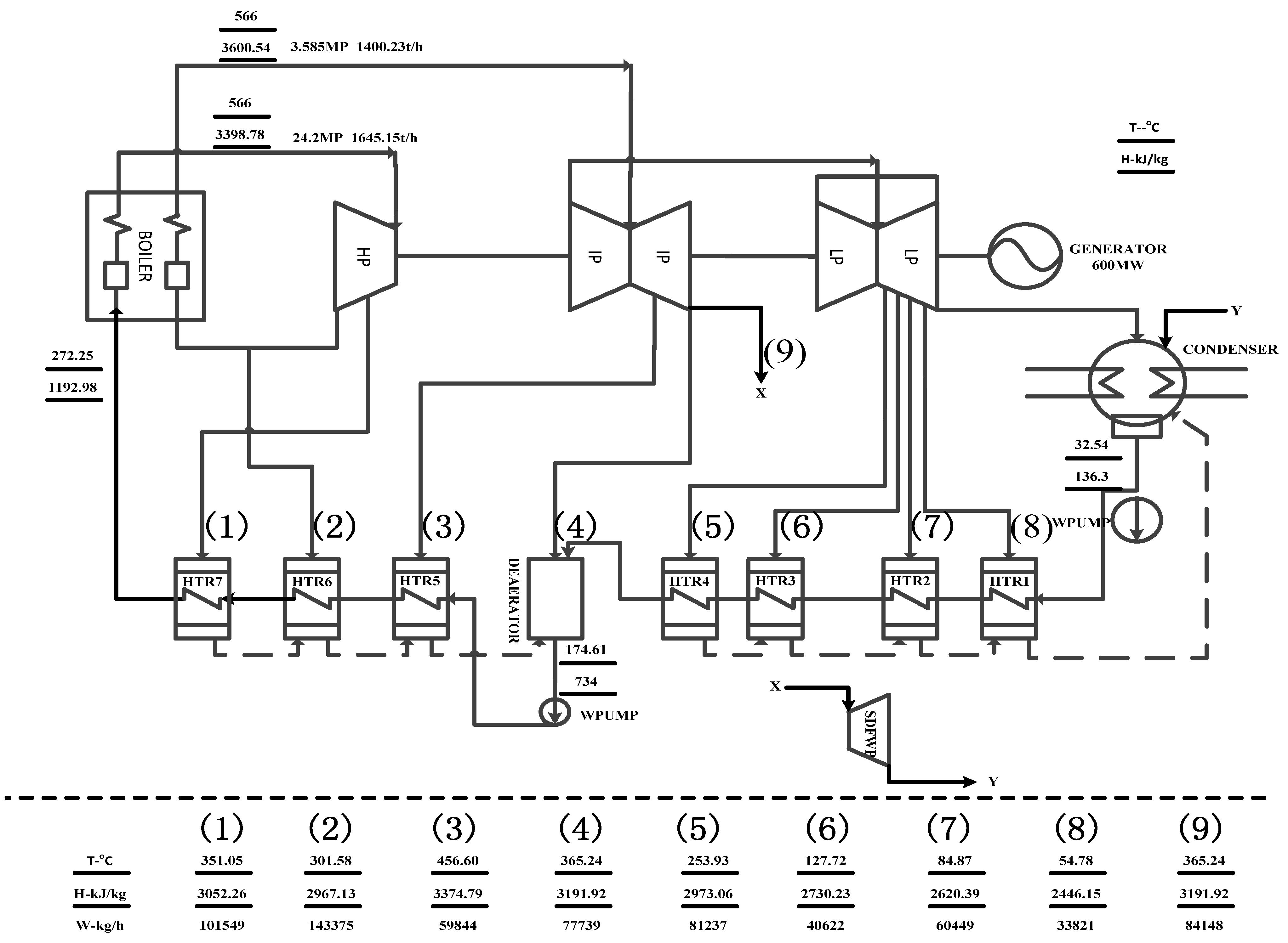
2.1. Coal-fired Power Plant
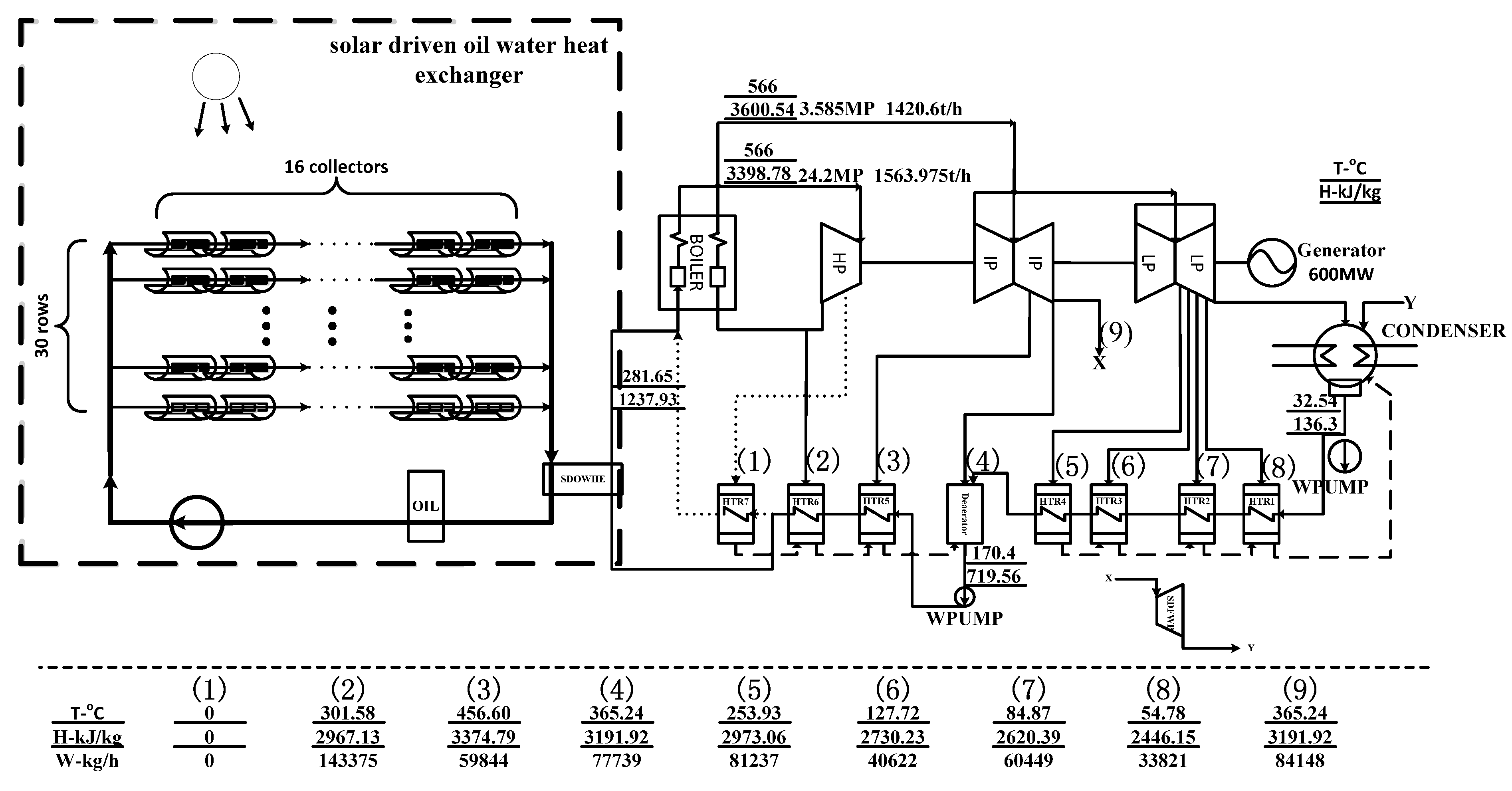
2.2. Solar-fired Coal-fired Power Plant
3. Methodology
3.1. Facilities in Power Generation Section
(1) Boiler
(2) Turbine
(3) Condenser
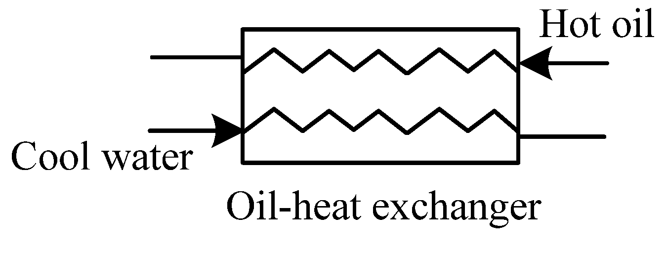
(4) Heat exchanger
3.2. Facilities in the Solar Field

4. Case Study
4.1. Fundamental Parameters

| Parameters | Values | Units |
|---|---|---|
| Capacity | 600 | MW |
| Parameters of main steam | 24.2/566/566 | MPa/°C/°C |
| Feedwater mass flowrate | 1645.15 | t/h |
| Condenser pressure | 4.9 | KPa |
| Feedwater temperature | 272.3 | °C |
| Coal consumption rate | 257.4 | g/kWh |
| Parameters | Values | Units |
|---|---|---|
| Solar irradiation | 925 | W/m2 |
| Area of per collector | 235 | m2 |
| Number of collector in each row | 16 | |
| Rows of collectors | 30 | Rows |
| Inlet temperature of heat transfer oil | 250 | °C |
| Outlet temperature of heat transfer oil | 328 | °C |
4.2. Results and Discussions


5. Effects of Solar Irradiations and Load Ratios
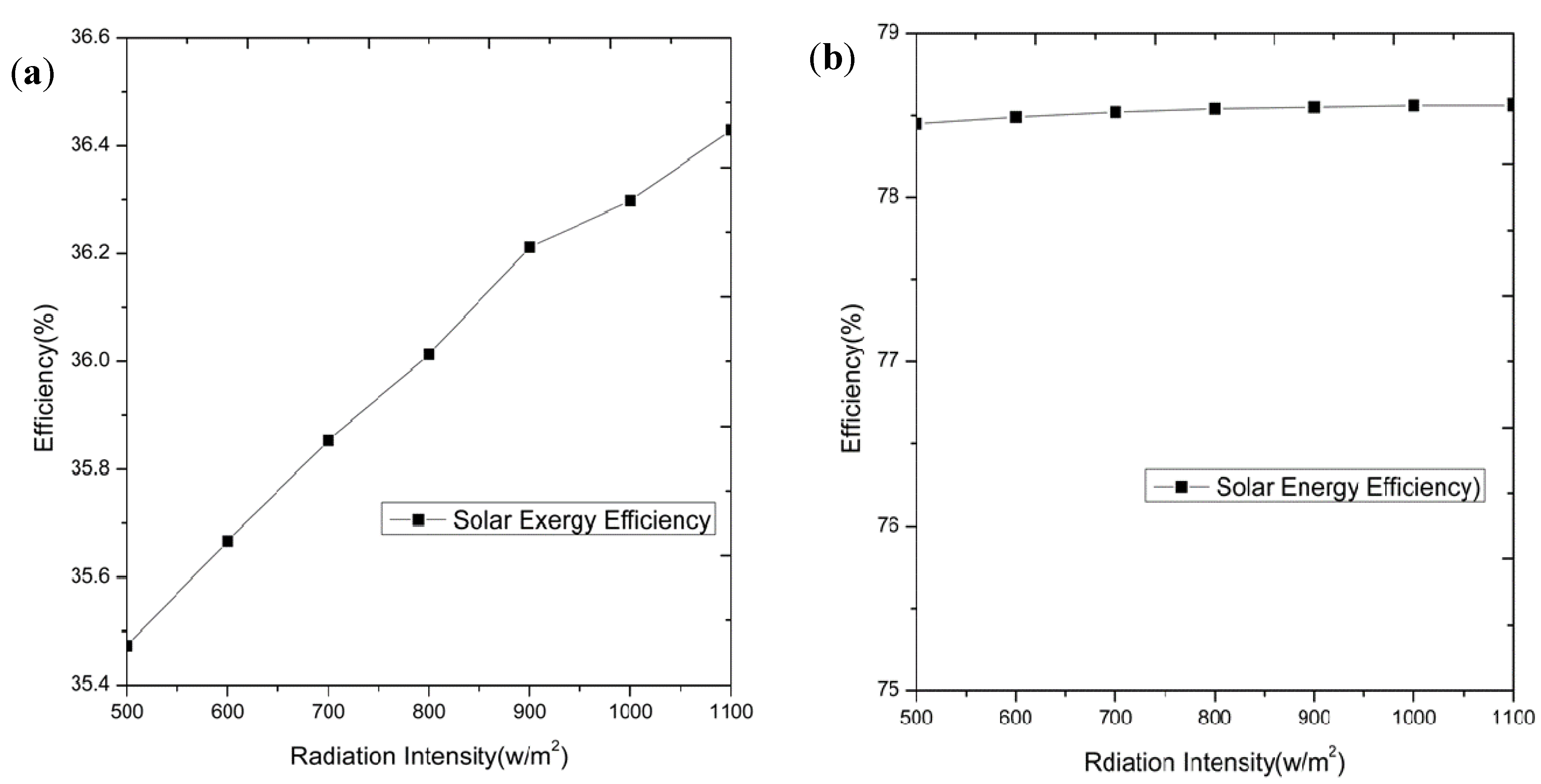
5.1. Effects of the Solar Irradiations


5.2. Effects of the Load Ratio
6. Conclusions
- (1)
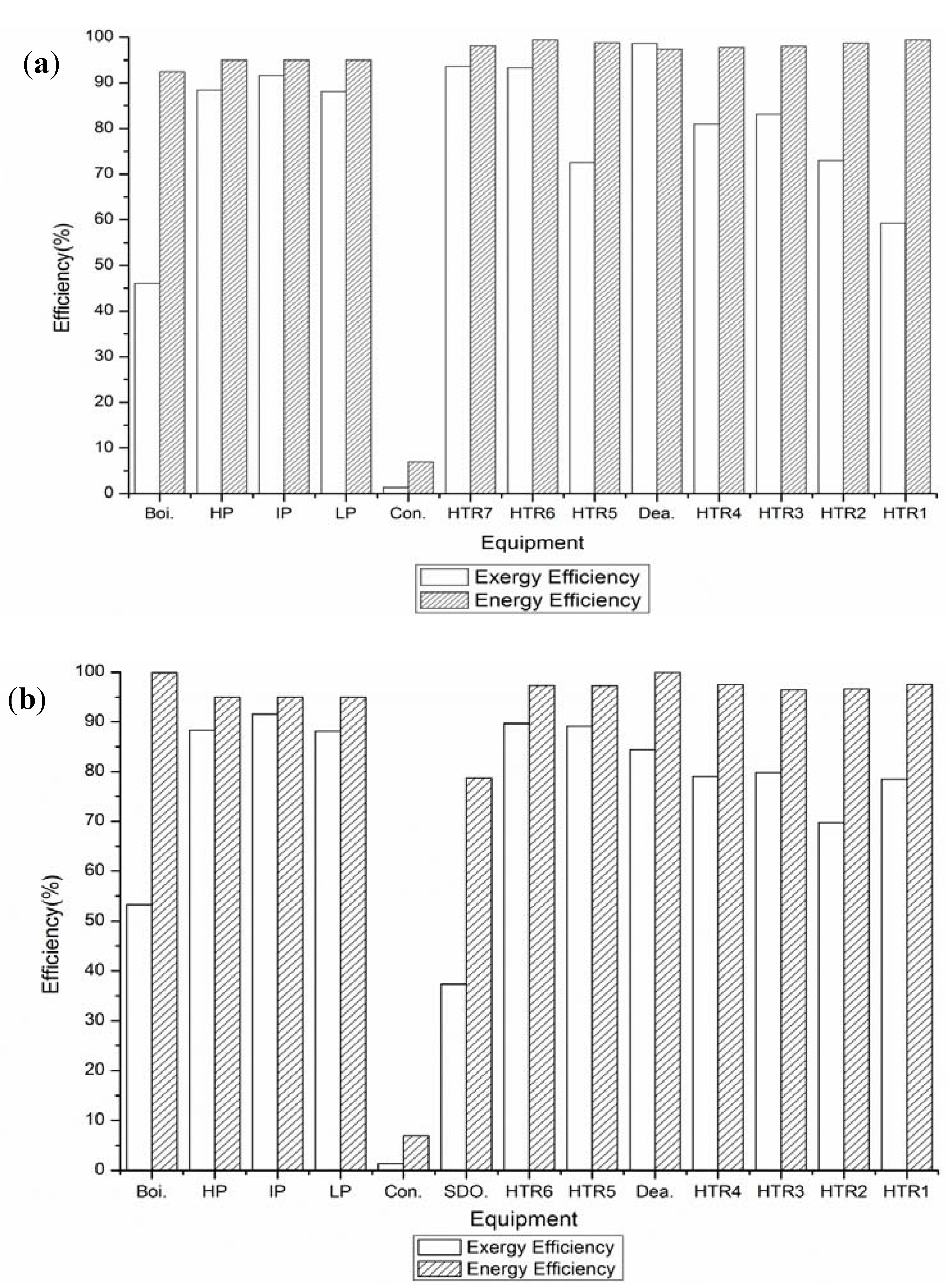
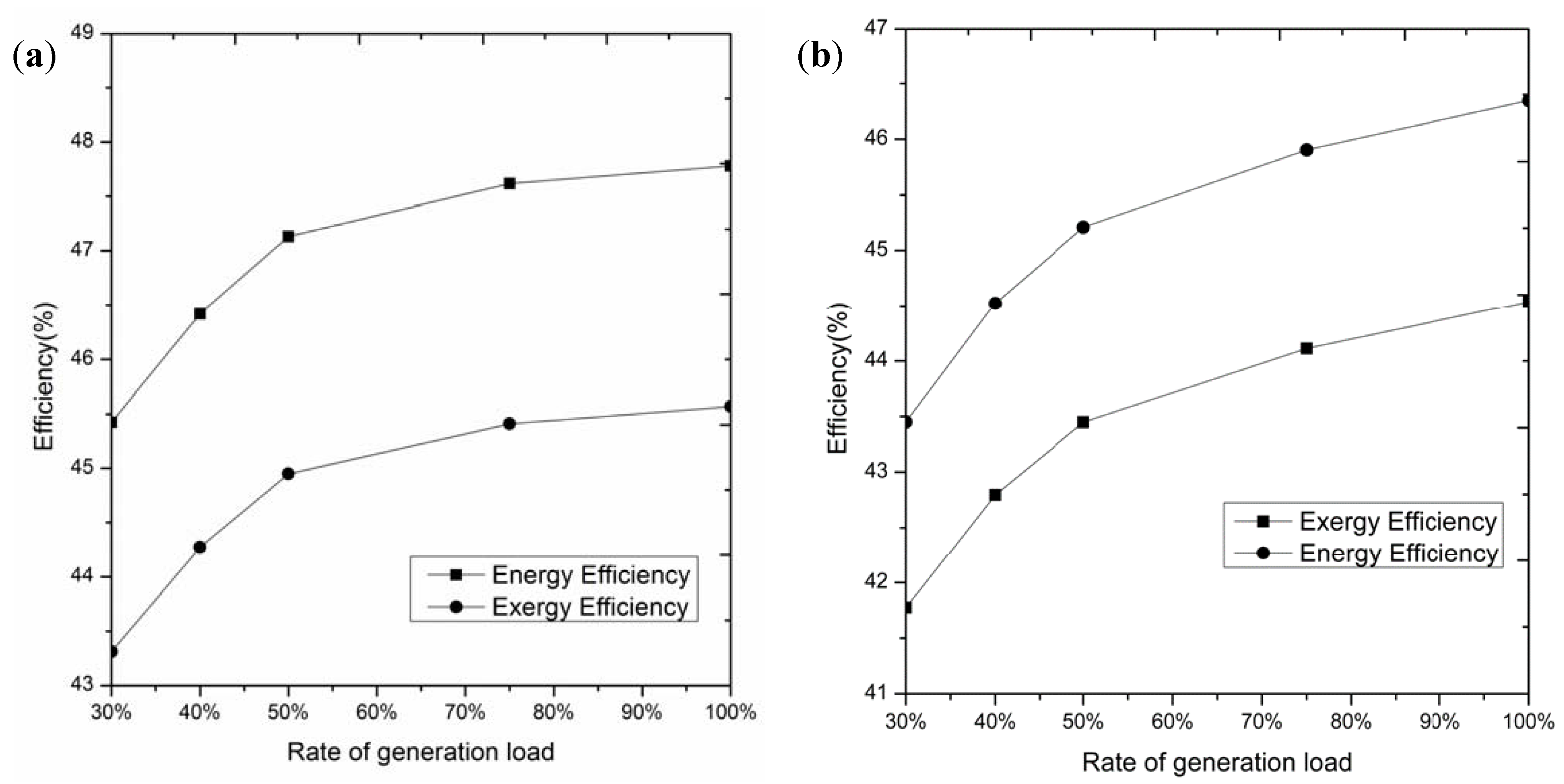
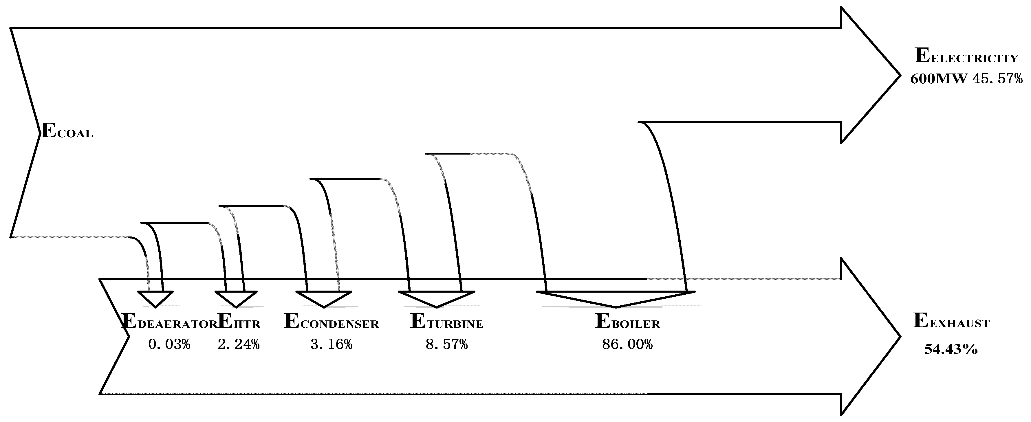
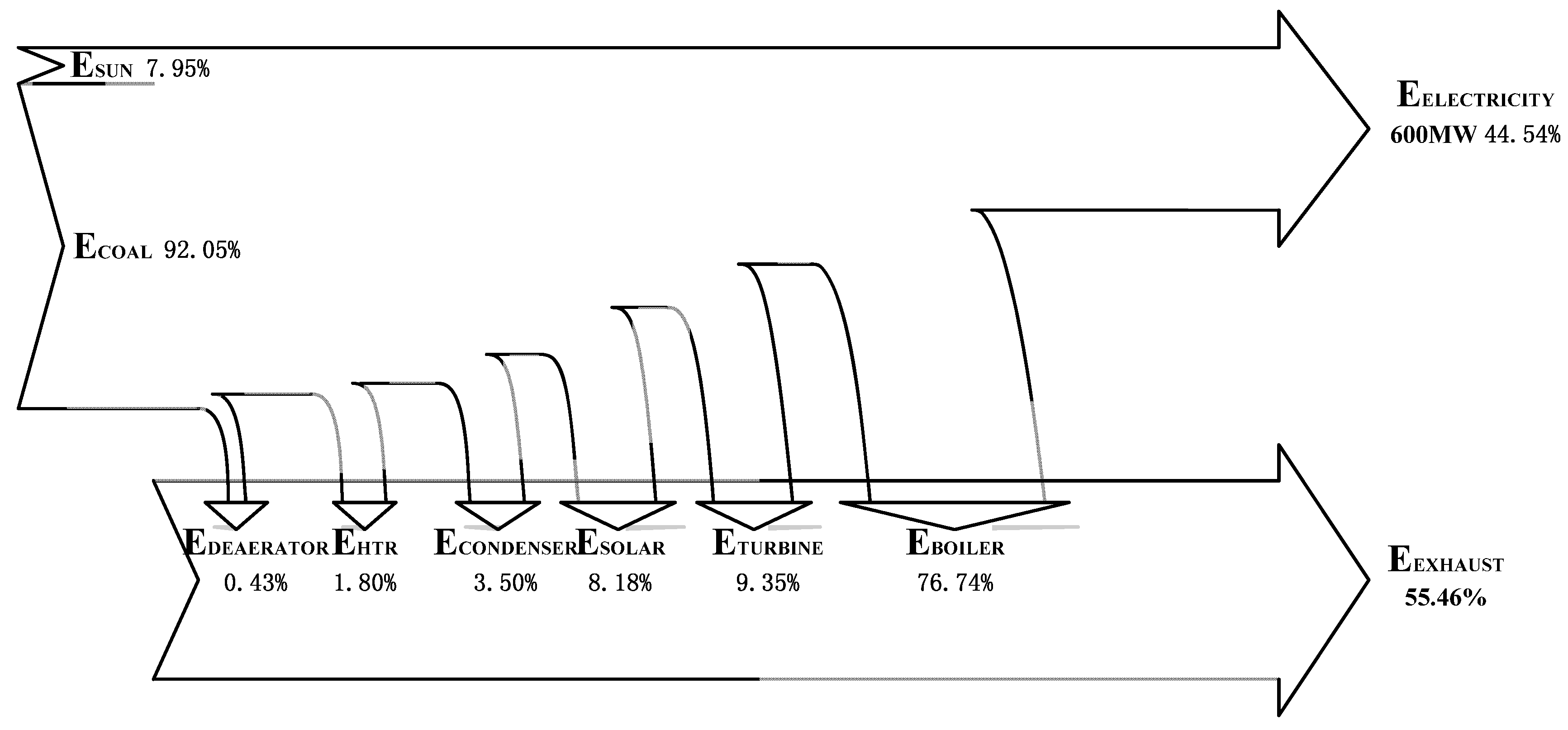
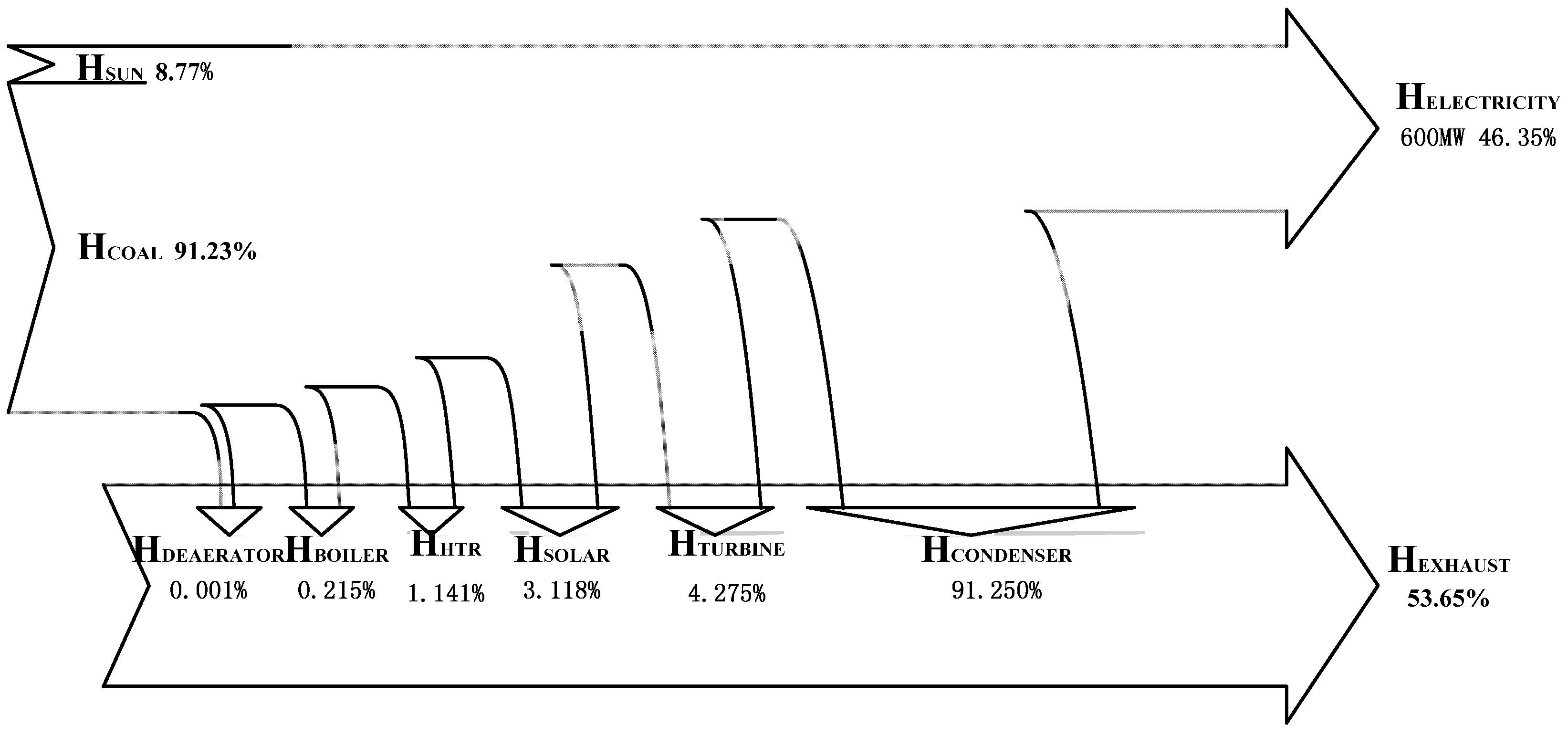
- When the solar irradiation is 925 W/m2 and load ratio of the unit is 100%, the exergy efficiency of the base plant is 45.57%, lower than the energy efficiency of the plant (47.78%); the exergy efficiency of the new plant is 44.54%, lower than the energy efficiency of the plant (46.35%). If the new plant is compared with the base plant, the exergy and energy efficiencies of the new plant are lower than those of the base plant compared to the base plant, and the new plant saves about 13.7 g/kWh of coal.
- (2)
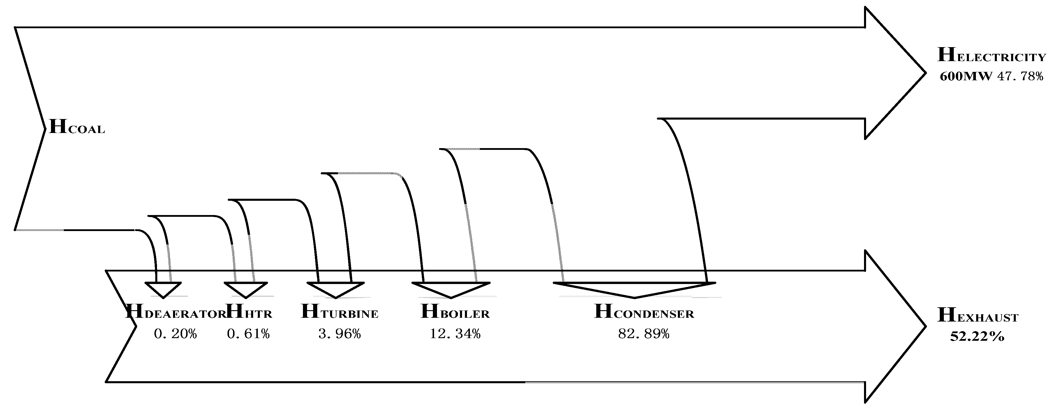
- When the solar irradiation is 925 W/m2 and load ratio of the unit is 100%, from the aspect of exergy losses, in the base plant, the largest exergy loss is from the boiler, accounting for about 86%, and the next largest exergy loss is from the turbines, while in the new plant, the largest exergy loss is still from the boiler, accounting for about 76.74%, and the next largest exergy loss is from the turbines. From the aspect of energy losses, in the base plant, the largest energy loss is in the condenser, accounting for about 82.89%, and the next energy loss is in the boiler; while in the new plant, the largest energy loss is still in the condenser accounting for about 91.25%, the next largest loss is in the turbines.
- (3)
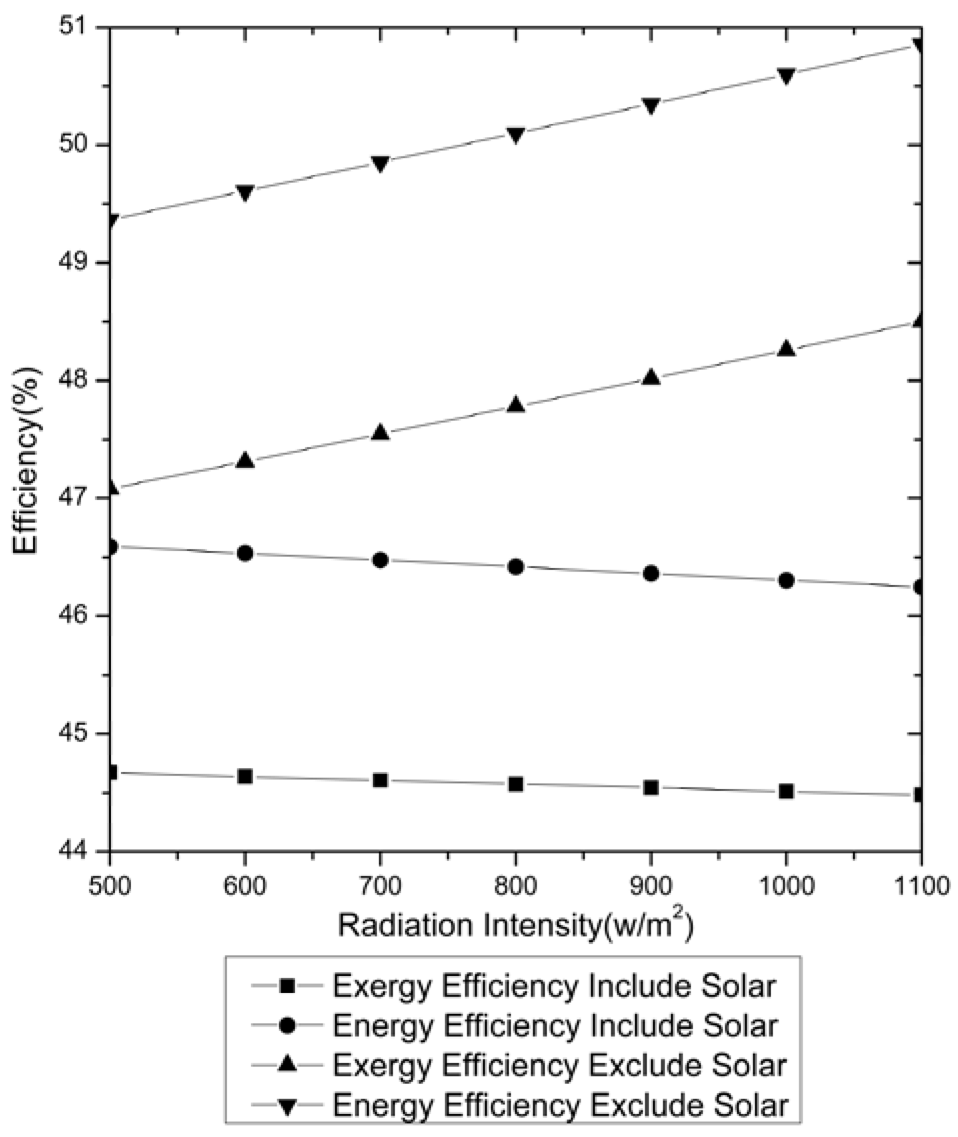
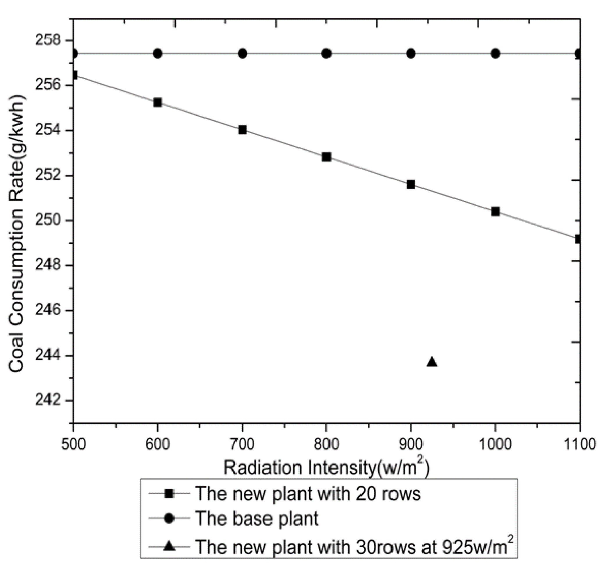
- When the load ratio of the unit is 100%, (i.e., with output of 600 MW), the solar irradiation differs from 500 W/m2 to 1,100 W/m2, the coal consumption rate reduces from 248.8 g/kWh to 241.6 g/kWh, saving coal from 8.6 g/kWh to 15.8 g/kWh.
- (4)
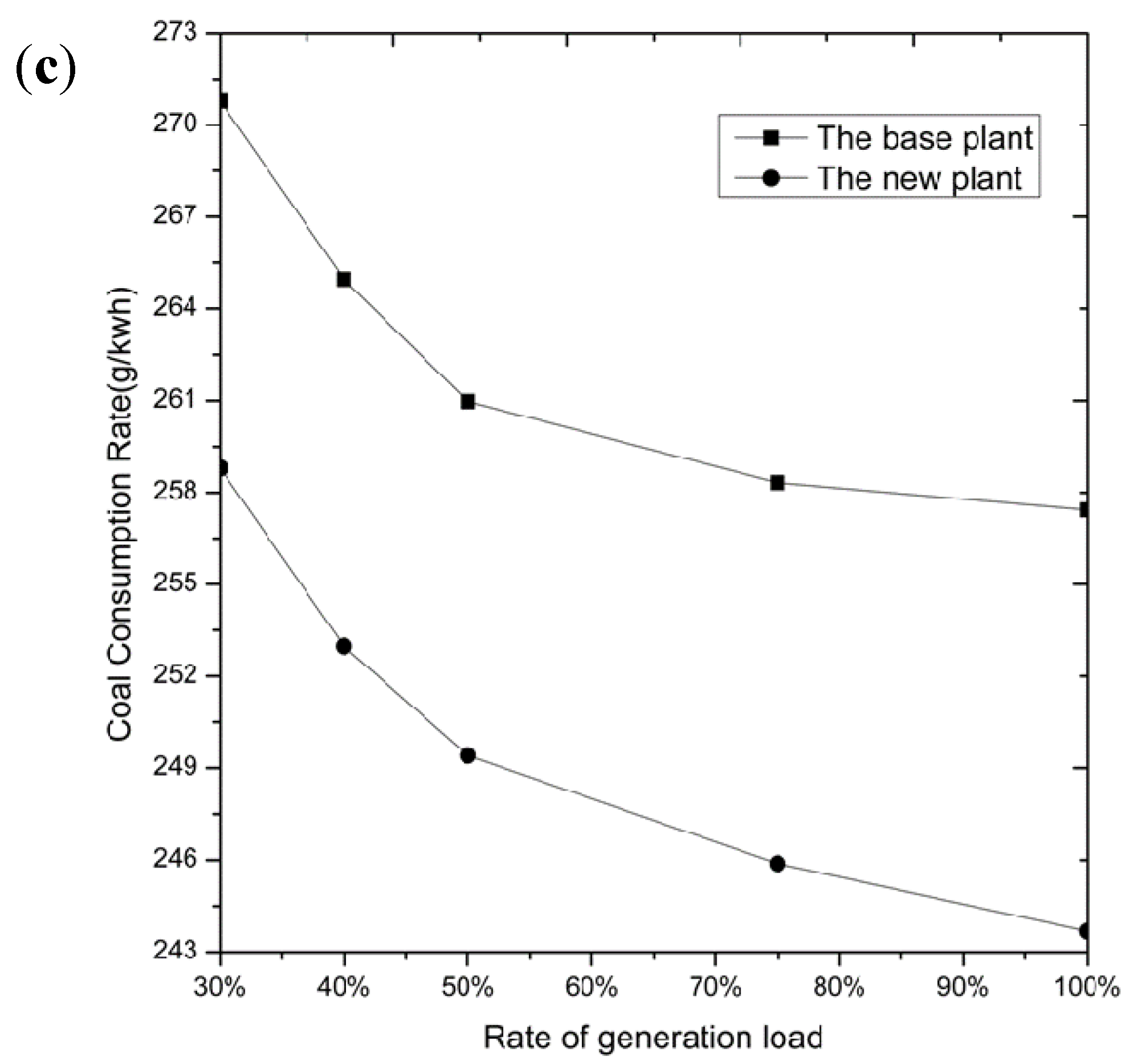
- When the solar irradiation is kept 925 W/m2 unchanged, the load ratio of the unit changes from 30% to 100%, the coal consumption rate of the base plant decreases from 270.8 g/kWh to 257.4 g/kWh. When the load ratio of the new plant increases from 30% to 100%, the coal consumption rate of the new plant decreases from 258.8 g/kWh to 243.7 g/kWh.
Acknowledgments
Nomenclature
heat supplied by the fuel (coal) | |
thermal efficiency of the boiler | |
flowrate of feedwater | |
the specific enthalpy of the inlet stream in the boiler | |
the specific enthalpy of the outlet stream in the boiler | |
the exergy efficiency of the boiler | |
the exergy of the fuel (coal) | |
the exergy of the inlet stream in the boiler | |
the exergy of the outlet stream in the boiler | |
he chemical exergy | |
the physical exergy | |
the output of the turbine | |
the flowrate of steam passing through the turbine | |
the specific enthalpy of the inlet steam | |
the specific enthalpy of the outlet steam | |
the isentropic efficiency of the turbine | |
the exergy efficiency of the turbine | |
the exergy of the inlet steam for the turbine | |
the exergy of the outlet steam for the turbine | |
The heat transferred from the condenser | |
the flowrate of the condensed water | |
the specific enthalpy of the inlet steam | |
the specific enthalpy of outlet steam | |
the thermal efficiency of the condenser | |
the exergy efficiency of the condenser | |
the inlet exergy of condenser | |
the outlet exergy of condenser | |
the flowrate of the steam extraction | |
the specific enthalpy of the steam extraction | |
the flowrate of inlet water for the heat exchanger | |
the specific enthalpy of the inlet water for the heat exchanger | |
the specific enthalpy of the outlet water for the heat exchanger | |
the flowrate of feedwater for the heat exchanger | |
the specific enthalpy of the outlet feedwater for the heat exchanger | |
the specific enthalpy of the outlet feedwater for the heat exchanger | |
the energy efficiency of the heat exchanger | |
the flowrate of the steam extraction for the heat exchanger | |
the specific exergy of the steam extraction for the heat exchanger | |
the inlet water flowrate for the heat exchanger | |
the specific exergy of the inlet water for the heat exchanger | |
the specific exergy of the outlet water for the heat exchanger | |
the flowrate of feedwater for the heat exchanger | |
the specific exergy of the inlet feedwater for the heat exchanger | |
the specific exergy of the outlet feedwater for the heat exchanger | |
the specific enthalpy of the outlet water for mixed heat exchanger | |
the specific exergy of the outlet water for mixed heat exchanger | |
the exergy of solar energy | |
the temperature of the environment | |
the temperature of the solar surface | |
the pressure of outlet water in oil-water heat exchanger | |
the pressure of inlet water in oil-water heat exchanger | |
the coefficient of the pressure drop | |
the mass flowrate of water | |
the enthalpy of outlet water | |
the enthalpy of inlet hot oil | |
the enthalpy of outlet hot oil | |
the mass flowrate of hot oil | |
the energy efficiency for the solar aided coal-fired power plant | |
the output power by the solar aided coal-fired power plant | |
the coal heat consumed by the solar aided coal-fired power plant | |
the input solar heat of the solar aided coal-fired power plant | |
the exergy efficiency for the solar aided coal-fired power plant | |
the coal exergy consumed by the solar aided coal-fired power plant | |
the input solar exergy of the solar aided coal-fired power plant | |
The coal consumption rate for coal fired power plant | |
The energy efficiency of the plant | |
The coal consumption rate for solar aided coal-fired power plant | |
Heat supplied by solar | |
Work output |
References
- Yang, Y.P.; Guo, X.Y.; Wang, N.L. Power generation from pulverized coal in China. Energy 2010, 35, 4336–4348. [Google Scholar] [CrossRef]
- Eric, H.; Yang, Y.P.; Nishimura, A.; Yilmaz, F. Solar-aided power generation. Appl. Energy 2010, 87, 2881–2885. [Google Scholar]
- Wang, Z.; Li, X.; Yao, Z. Concentrating solar power development in China. Renew. Energy 2010, 35, 981–988. [Google Scholar] [CrossRef]
- Report of China Energy Chamber of Commerce. Available online: http://www.cnecc.org.cn/dispArticle.asp?id=7838/ (accessed on 28 December 2010).
- Zoschak, R.J.; Wu, S.F. Studies of the direct input of solar energy to a fossil-fueled central station steam power plant. Sol. Energy 1975, 17, 297–305. [Google Scholar] [CrossRef]
- Jamel, M.S.; Abd Rahman, A.; Shamsuddin, A.H. Advances in the integration of solar thermal energy with conventional and non-conventional power plants. Renew. Sustain. Energy Rev. 2013, 20, 71–81. [Google Scholar] [CrossRef]
- Gupta, M.K.; Kaushik, S.C. Exergetic utilization of solar energy for feedwater preheating in a conventional thermal power plant. Int. J. Energy Res. 2009, 33, 593–604. [Google Scholar] [CrossRef]
- Yang, Y.P.; Yan, Q.; Zhai, R.R.; Eric, H. An efficient way to use medium-or-low temperature solar heat for power generation—Integration into conventional power plant. Appl. Therm. Eng. 2011, 31, 157–162. [Google Scholar] [CrossRef]
- Pai, B.R. Augmentation of thermal power stations with solar energy. Sadhana 1991, 16, 59–74. [Google Scholar] [CrossRef]
- Ying, Y.; Hu, E.J. Thermodynamic advantages of using solar energy in the regenerative Rankine power plant. Appl. Therm. Eng. 1999, 19, 1173–1180. [Google Scholar] [CrossRef]
- Price, H.; Lupfert, E.; Kearney, D.; Zarza, E.; Cohen, G.; Gee, R. Advances in parabolic trough solar power technology. J. Sol. Energy Eng. 2002, 124, 109–125. [Google Scholar] [CrossRef]
- Eck, M.; Zarza, E.; Eickhoff, M.; Rheinlander, J.; Valenzuela, L. Applied research concerning the direct steam generation in parabolic troughs. Sol. Energy 2003, 74, 341–351. [Google Scholar] [CrossRef]
- Zhao, Y.; Hong, H.; Zhang, X.; Jin, H. Integrating mid-temperature solar heat and post-combustion CO2-capture in a coal-fired power plant. Sol. Energy 2012, 86, 3196–3204. [Google Scholar] [CrossRef]
- Kotas, T.J. The Exergy Method of Thermal Plant Analysis; Butterworths: London, UK, 1985. [Google Scholar]
- Bejan, A. Advanced Engineering Thermodynamics; Wiley Interscience: Durham, UK, 1988. [Google Scholar]
- Habib, M.A.; Zubair, S.M. Second-law-based thermodynamic analysis of regenerative-reheat Rankine-cycle power plants. Energy 1992, 17, 295–301. [Google Scholar] [CrossRef]
- Rosen, M.A.; Dincer, I. Exergoeconomic analysis of power plants operating on various fuels. Appl. Therm. Eng. 2003, 23, 643–658. [Google Scholar] [CrossRef]
- Singh, O.K.; Kaushik, S.C. Energy and exergy analysis and optimization of Kalina cycle coupled with a coal fired steam power plant. Appl. Therm. Eng. 2013, 51, 787–800. [Google Scholar] [CrossRef]
- Siva Reddy, V.; Kaushik, S.C.; Tyagi, S.K. Exergetic analysis of solar concentrator aided natural gas fired combined cycle power plant. Renew. Energy 2012, 39, 114–125. [Google Scholar] [CrossRef]
- Yan, Q.; Eric, H.; Yang, Y.P.; Zhai, R.R. Evaluation of Solar Aided Thermal Power Generation with Various Power Plants. Int. J. Energy Res. 2011, 35, 909–922. [Google Scholar] [CrossRef]
- Baghernejad, A.; Yaghoubi, M. Exergy analysis of an integrated solar combined cycle system. Renew. Energy 2010, 35, 2157–2164. [Google Scholar] [CrossRef]
- Qian, S.; Yang, D. The calculation model and equations of chemical exergy for complex substance. J. East China Inst. Chem. Technol. 1986, 12, 95–104. [Google Scholar]
- Patnode, A.M. Simulation and Performance Evaluation of Parabolic Trough Solar Power Plants. M.Sc. Thesis, University of Wisconsin-Madison, Madison, WI, USA, 2006. [Google Scholar]
- Thorsten, A.S. Automatic Control of the 30 MWe SEGS VI Parabolic Trough Plant. M.Sc. Thesis, The University of Wisconsin-Madison, Madison, WI, USA, 2002. [Google Scholar]
- Thorsten, A.S.; Nathan, B.; John, W.M.; William, A.B. Automatic control of a 30MWe SEGD VI parabolic trough plant. Sol. Energy 2004, 76, 187–193. [Google Scholar]
© 2013 by the authors; licensee MDPI, Basel, Switzerland. This article is an open access article distributed under the terms and conditions of the Creative Commons Attribution license (http://creativecommons.org/licenses/by/3.0/).
Share and Cite
Zhai, R.; Zhu, Y.; Yang, Y.; Tan, K.; Hu, E. Exergetic and Parametric Study of a Solar Aided Coal-Fired Power Plant. Entropy 2013, 15, 1014-1034. https://doi.org/10.3390/e15031014
Zhai R, Zhu Y, Yang Y, Tan K, Hu E. Exergetic and Parametric Study of a Solar Aided Coal-Fired Power Plant. Entropy. 2013; 15(3):1014-1034. https://doi.org/10.3390/e15031014
Chicago/Turabian StyleZhai, Rongrong, Yong Zhu, Yongping Yang, Kaiyu Tan, and Eric Hu. 2013. "Exergetic and Parametric Study of a Solar Aided Coal-Fired Power Plant" Entropy 15, no. 3: 1014-1034. https://doi.org/10.3390/e15031014