1. Introduction
The increase in the demand for energy, the search for clean energies without greenhouse gas emissions and the high cost of hydrocarbons have generated the search for new clean and renewable sources. A track, which represents a usable source, is the recovery of the waste heat [
1] generated in industry by processes, such as combustion of solid waste, geothermal energy, power plants or in car exhaust [
2]. In this process, temperature values ranging between 360 to 1,000 K have been reported for these heat sources in the literature [
3].
Solid state devices, which represent a solution to this proposal, are known as thermoelectric devices or thermoelectric modules (TEM) [
4] and have the property of converting heat into electricity, without emission of pollutants. Thermoelectric power generation, for example, is a promising way to achieve efficient waste energy harvesting. Due to their advantages of compact structure, high reliability, no vibration and direct electric energy conversion [
5], the TEMs are applied in infrared sensors, computer chips, artificial satellites and power systems in space probes [
6]. They are also used for the supply of electricity in remote control and monitoring of lines of oil or gas and plants, navigational aids, telecommunications systems and cathodic protection of pipelines [
7]. They are very useful in remote areas or where power supply is considered critical. Currently, solar collectors that seek to take advantage of the radiation captured to generate electricity are being designed [
8,
9].
In general, thermoelectric systems (TES) operate on the basis of the transport of energy, entropy and of charge carriers in a conductor or semiconductor material by means of the basic thermoelectric effects, such as Seebeck and Peltier effects. In fact, when an electric field is applied to a TEM, the irreversible process, which occurs as an thermoelectric elemental, are electric conduction (electric current due to an electric potential), heat conduction (heat flux due to a temperature gradient), a cross effect (electric current due to a temperature gradient) and the appropriate reciprocal effect (heat flux due to an electric potential gradient). In the theoretical formulation of irreversible thermodynamics, using the Onsager reciprocal relationship, the thermoelectric effects in the TES are clearly presented [
10].
The efficiency of thermoelectric devices is characterized by a quantity known as the Figure of Merit,
, which is a function of the transport properties of the material. In fact, The maximum efficiency of a thermoelectric material for both power generation and cooling is determined by its
, where
T is the absolute temperature and
Z is given by:
where
ρ is the electrical resistivity,
α is the Seebeck coefficient and
κ is the thermal conductivity [
4]. However, the TEMs have the disadvantage of their low efficiency, which limits the extent of their applications. The search for a greater Figure of Merit has resurfaced in this field as an intense research activity, which has grown exponentially in the last two decades [
11]. Works include [
12], The quantum confinement of electrons and holes, the study of molecular junctions, the use of nanostructures, which improve the quality of the transport of electrons and phonons and structures of quantum dots, that is, to assume the thermoelectric in a dimension zero [
13]. In other works, it has been proposed that by reducing the thermal conductivity of the lattice of the material, it will improve the value of
, also by performing tests with polymeric materials/organic. Other research has focused on geometric factors based on parameters, such as the length and cross sectional area of the thermocouples.
A new generation of devices, known as segmented thermoelectric generators, has emerged as a potential resource for power generation, using the energy from waste [
4]. The segmentation technique [
3,
14] consists in uniting different thermoelectric materials to form the branches of the thermocouple. The principle involved is that to achieve high efficiency, both large temperature differences and high Figure of Merit materials are desired. Since the material thermoelectric properties (Seebeck coefficient, electrical resistivity, thermal conductivity) vary with temperature, it is not desirable or even possible to use the same material throughout an entire, large temperature drop. Ideally, different materials can be segmented together, such that a material with high efficiency at high temperature is segmented with a different material with high efficiency at low temperature. In this way, both materials are operating only in their most efficient temperature range.
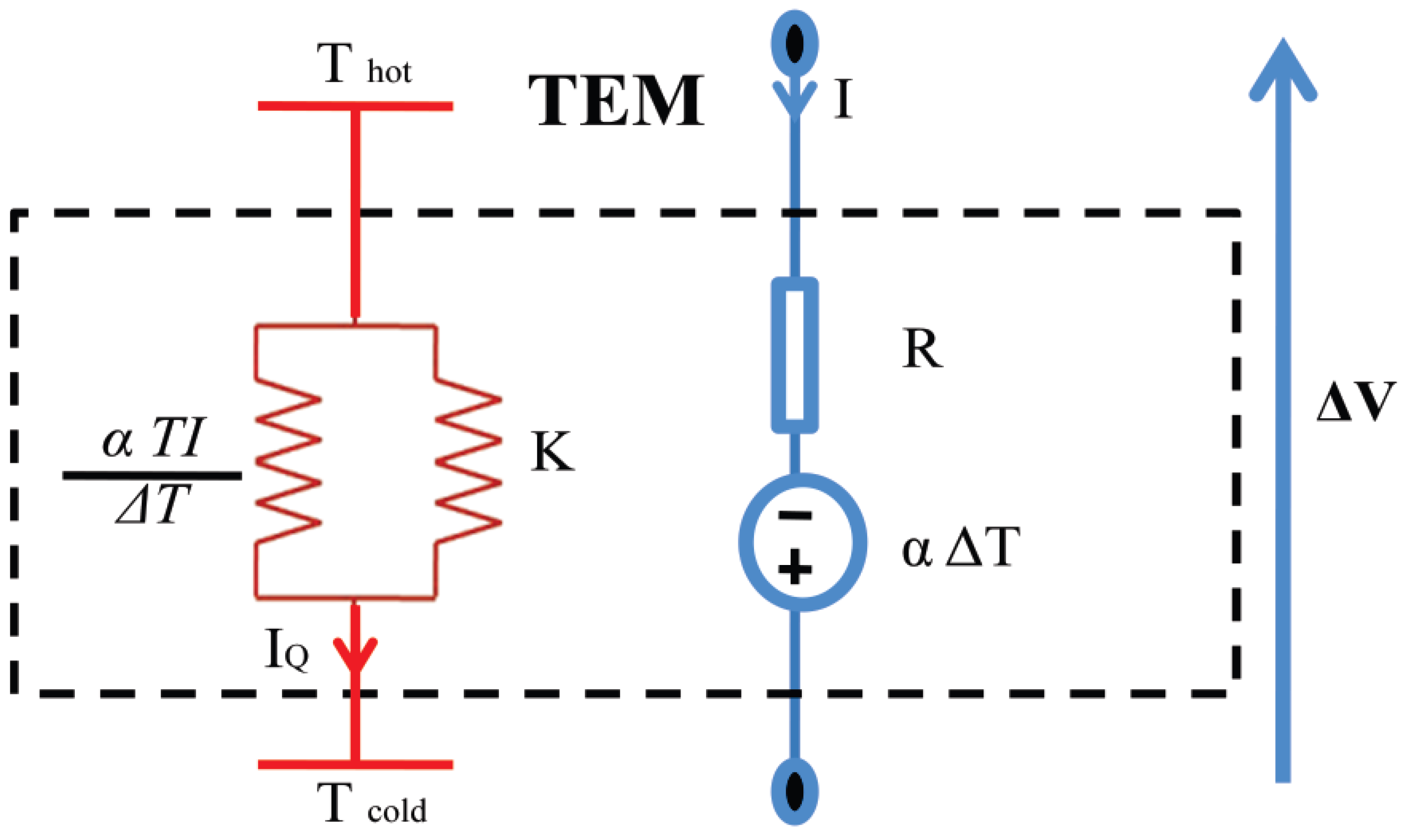
Another analytical treatment for these systems is based on the (circuit) theory of transport [
15], in which it is possible to consider a simple model of a thermoelectric system that accounts for the heat transport by electrical carriers; this results in the introduction of the corresponding thermoelectric circuit for a TEM; see
Figure 1.
Figure 1.
Thermoelectric generator segmented, each P- or N-type branch consists of two different materials; figure from ref. [
16].
Figure 1.
Thermoelectric generator segmented, each P- or N-type branch consists of two different materials; figure from ref. [
16].
In this model, each TEM is characterized by its internal electrical resistance,
R, thermal conductance under open electrical circuit condition,
K, and Seebeck coefficient,
α. All these coefficients are supposed constant. The TEM is subjected to a temperature difference,
, and its average temperature is
T. With these considerations, we analyze three configurations of TES, for which each one is composed of different TEMs. The configurations, considered in this paper, correspond to analogous practical TEM devices that include segmented and conventional TEMs. In this novel treatment, we are free to choose the thermal and electrical configurations, which permits an easy derivation of the equivalent parameters of the TES systems as a whole. The study of the different configurations of TEMs has been analyzed by experimental treatments for a long time. For example, the effect of hot junction temperature and Figure of Merit on the efficiency of thermocouples has been studied [
17]. Recently, it was reported by studies on an Thermoelectric Generation Subsystem Model for Heat Recovery Simulations [
18] in which experimental data are gathered by comparing thermoelectric modules with varying Seebeck coefficients and internal electrical resistances to confirm that there exists a reduction in power generation potential when parameters of electrically linked TEMs differ. In this work, we show a method to distinguish the impact on the Figure of Merit when the parameters of the TEMs link thermoelectric modules electrically and thermally in series or in parallel.
This paper is organized as follows: In
Section 2, we present thermoelectric systems (TESs) in different configurations. In
Section 2.1, we consider the behavior of a TES, which is thermally and electrically connected in series. In
Section 2.2 and
Section 2.3, we analyze a TES that is thermally and electrically connected in parallel and a TES that is connected thermally in parallel and electrically in series, respectively. For each TES, its Figure of Merit equivalent,
, is obtained. In
Section 3, numerical results for
and for maximum efficiency,
, and their behavior as a function of
α are shown for each configuration. Finally, in
Section 4, we present our conclusions and future work is discussed briefly.
2. Thermoelectric System (TES) in Different Configurations
In this work, we consider a thermoelectric system (TES) composed of three thermoelectric modules (TEM) in different configurations, namely, (a) a two-stage TES thermally and electrically connected in series (SC-TES); (b) a segmented-conventional TES thermally and electrically connected in parallel (PSC) and (c) a mixed segmented-conventional TES connected thermally in parallel and electrically in series.
For our analysis, we assume that the only electrical resistance is that of the thermocouple branches of the TEM. We also assume that there is zero thermal resistance between the ends of the branches and the heat source and sink and that the only paths for transferring heat between the source and sink are the thermocouple branches of the TEM, that is, we ignore conduction via ambient, convection and radiation [
19]. Finally, we assume that the internal electrical resistance,
R, thermal conductance under open electrical circuit condition,
K, and Seebeck coefficient,
α, do not vary with the temperature.
Our purpose is to find the Figure of Merit
, as already had been mentioned, in terms of the three parameters, namely,
,
and
, of the equivalent TES, for configurations considered here. Additionally, we provide a suggested realistic system for each configuration. Notice that we have suggested a
representative practical device of what the real segmented TES system will look like [
20].
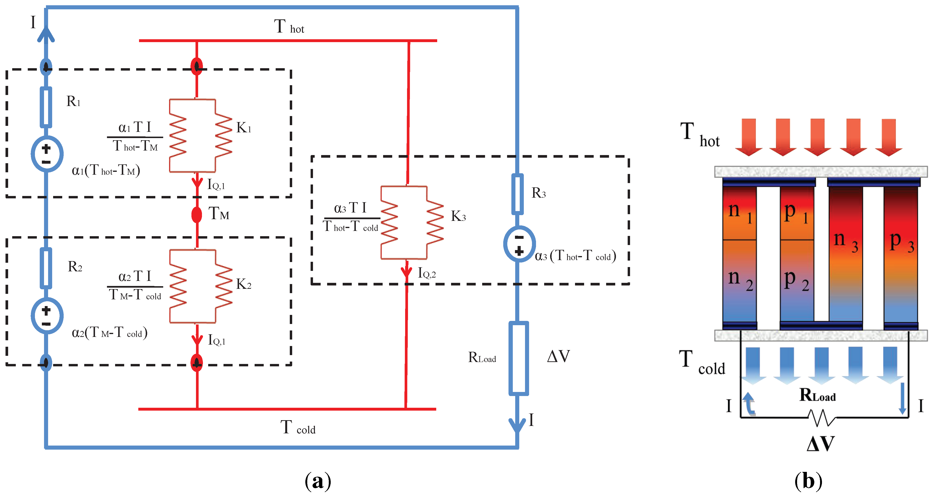
2.1. Two-Stage Thermoelectric System Connected in Series (SC-TES)
We consider a two-stage thermoelectric system (TES) composed of three TEM thermally and electrically connected in series (SC-TES). The schematic of this system is shown in
Figure 2. The first stage (bottom stage) consist of two different thermoelectric modules (TEM). Following Apertet
et al. [
16], each of the TEM is characterized by its internal electrical resistance,
, thermal conductance under open electrical circuit condition,
, and its Seebeck coefficient,
, where
i can be
or
, as appropriate. All these coefficients are supposed constant. The whole system is subjected to a temperature difference,
, and its average temperature is
T.
Figure 2.
Schematic representation of a thermally and electrically connected in series (SC-TES) thermoelectric system composed of two stages thermally and electrically connected in series. (a) SC-TES; (b) practical device related to SC-TES.
Figure 2.
Schematic representation of a thermally and electrically connected in series (SC-TES) thermoelectric system composed of two stages thermally and electrically connected in series. (a) SC-TES; (b) practical device related to SC-TES.
It has been shown [
10], by using the theory of linear response, that the electrical and thermal currents,
and
, are functions of the generalized forces [
21], related to the differences in voltage,
, and temperature,
, applied to the thermoelectric generator:
where
T is the average temperature. The heat flux within a segment in any of the TEMs is:
In this model, it is considered that the heat flux is constant along a TEM and equal to its average value. In each figure, the heat conveyed by the electrical current is represented by the additional thermal terms, namely,
. These terms depend on electrical load through the electrical current,
[
22]. Further, the approximation is made that the mean temperature,
T, can be considered as constant through the system, as it is compared to the temperature difference between the heat reservoirs at
and
temperatures.
By continuity of heat flux through the interface between stages of the SC-TES:
from which we obtain the average temperature at the interface between the stages [
23]:
Since all components are electrically connected in series, the total voltage is given by:
substituting the value of
in the last equation, we have:
From this equation, we identified the equivalent series Seebeck coefficient,
, and the electrical resistance equivalent series,
, as follows:
where:
Considering the open circuit condition for the system,
, we find that the equivalent thermal conductance for the whole system:
We define a Figure of Merit in terms of equivalent quantities [
23]:
By replacing the results obtained in Equations (
8)–(
11), we have:
or:
where:
and:
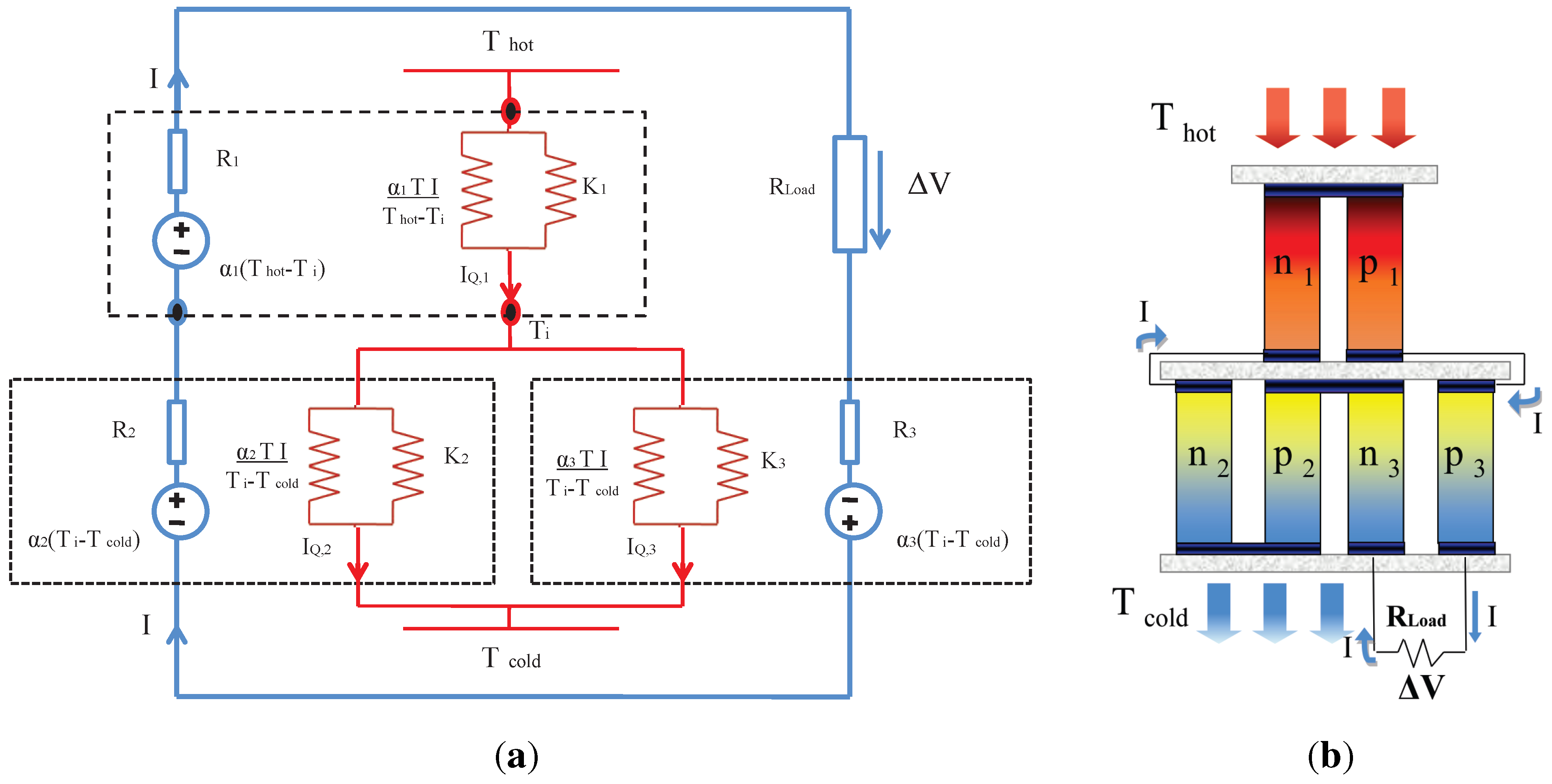
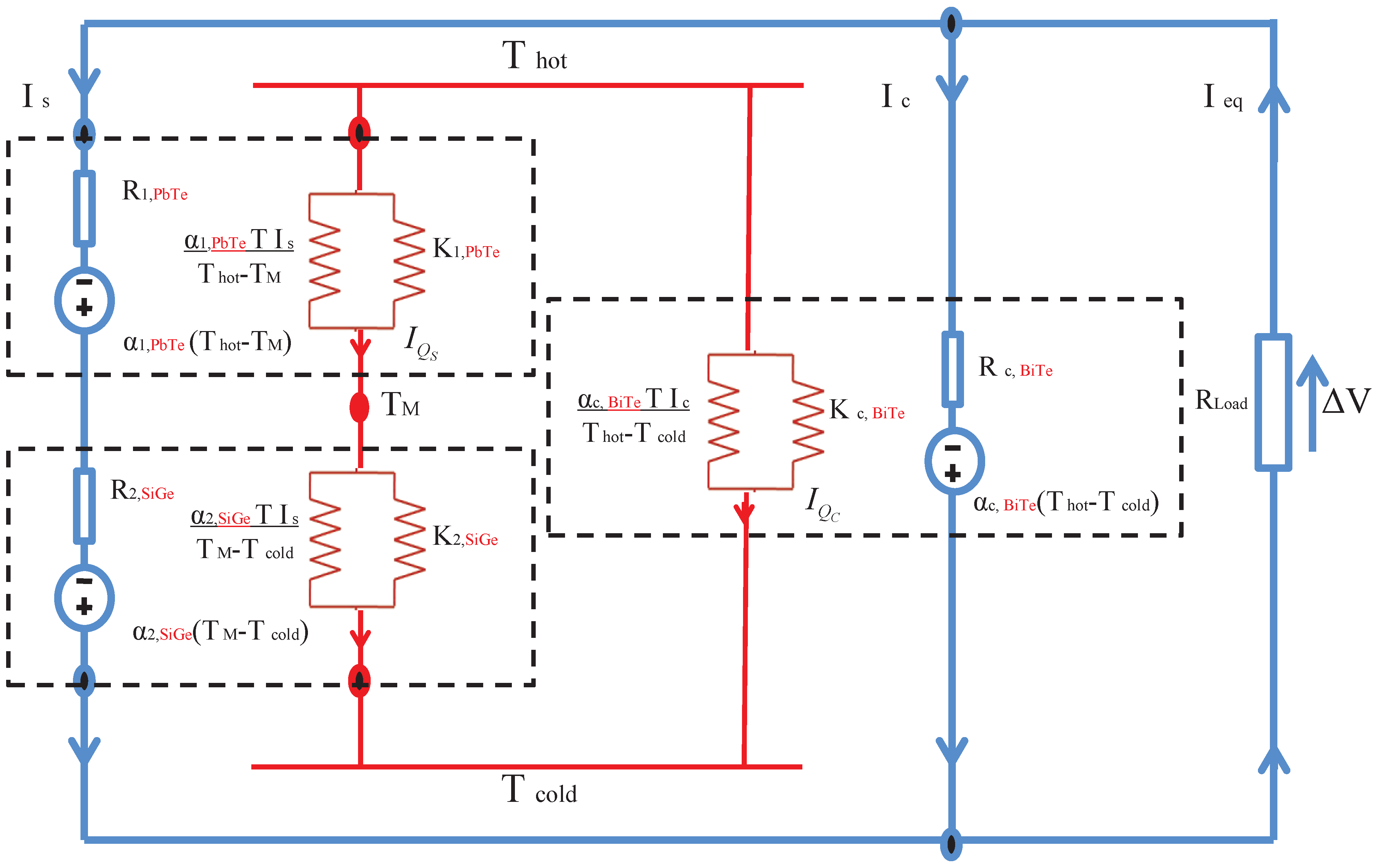
2.2. Segmented-Conventional Thermoelectric System in Parallel (PSC)
In this section, we consider a TES system, which is composed by a segmented TEM and a conventional TEM. These TEMs are thermally and electrically connected in parallel (PSC-TES), as is shown in
Figure 3.
Figure 3.
Schematic representation of a segmented-conventional TES thermally and electrically connected in parallel thermoelectric system (PSC-TES) composed by a segmented TEM and conventional TEM thermally and electrically connected in parallel. (a) PSC-TES; (b) practical device related to PSC-TES.
In this system, we have two electric currents namely,
, for the segmented TEM, and this current is the same for both components and
for the conventional TEM. By conservation of the electrical current [
16]:
The heat flux through the whole system is the sum of heat fluxing flowing through the segmented generator, and the heat flux in the conventional generator. Thus:
To obtain the equivalent electrical resistance,
, using Equation (
17), an isothermal condition,
, is required. Under this condition, we recover the usual expression of equivalent electrical resistances for an ohmic circuit. Thus, we get:
where
is the internal electrical resistance of the conventional TEM and
is the electrical resistance of the segmented TEM:
and:
Assuming the condition of a closed circuit,
, and applying Equation (
17), we have for the Seebeck coefficient equivalent [
16]:
where:
To determine the equivalent thermal conductance,
, we use the open circuit condition,
, which is satisfied when
, and, due to the heat flow, is preserved:
where:
Under open circuit condition,
, so that
. Applying this result, we have for
I:
Using this last result in Equation (
25), we have:
Now, we can write the Figure of Merit for this PSC-TES System:
Using the results obtained in Equations (
19), (
22) and (
27), we have:
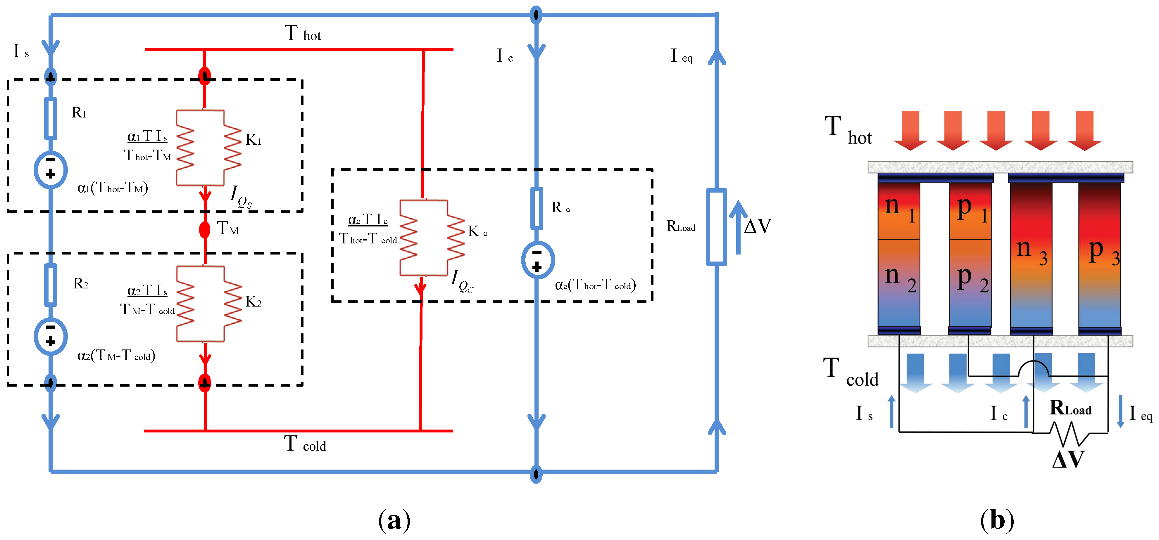
2.3. Mixed Segmented-Conventional Thermoelectric System (SSC-TES)
In this case, we have considered a thermoelectric system (SSC-TES) composed by a segmented TEM and conventional TEM, but they are thermally connected in parallel and electrically connected in series; see
Figure 4.
Figure 4.
Schematic representation of a mixed segmented-conventional thermoelectric system (SSC-TES) composed by segmented TEM and conventional TEM thermally connected in parallel and electrically connected in series. (a) SSC-TES; (b) practical device related to SSC-TES.
Figure 4.
Schematic representation of a mixed segmented-conventional thermoelectric system (SSC-TES) composed by segmented TEM and conventional TEM thermally connected in parallel and electrically connected in series. (a) SSC-TES; (b) practical device related to SSC-TES.
To obtain the equivalent quantities of this SSC-TES, we proceed in a similar manner to
Section 2.1. At the interface of the two materials for the segmented TEM, we have a continuity of heat flux:
From this last equation, we derive the average temperature between the two components of the segmented TEM:
According to [
16], the segmented TEM can be considered as a system of two thermoelectric TEMs connected in series. Thus, the equivalent voltage is given by:
Using the value for
obtained in Equation (
31):
As this segmented TEM is electrically connected in series with a conventional generator, then the voltage equivalent to the entire system is obtained:
Using the last results, we can identify the equivalent quantities for this system, namely, the Seebeck coefficient equivalent:
the equivalent electrical resistance:
where the term obtained by [
16] appears:
and the thermal conductance, which is given by:
Finally, the equivalent Figure of Merit for the whole system is given by:
3. Results and Discussion
The Figure of Merit for each of the three thermoelectric systems considered in this work has been evaluated using the experimental values of the three parameters of the each TEM, namely, its isothermal electrical resistance,
R, its thermal conductance under open electrical circuit condition,
K, and its Seebeck coefficient,
α, for the thermoelectric materials, BiTe, PbTe and SiGe [
24,
25,
26].
Now, we observe variations in the numeric value of the Figure of Merit,
, for each case being considered. For this purpose, we change in cyclical order the thermoelectric materials for each of the TEM in the whole system. Thus, we obtain the value of the Figure of Merit,
, and the corresponding maximum efficiency (see
Section 3.1) for each specific arrangement of materials in each configuration. Our results are shown in the
Table 1.
Table 1.
Numerical values of and in each equivalent thermoelectric system for different arrangements of the TE-materials.
Table 1.
Numerical values of and in each equivalent thermoelectric system for different arrangements of the TE-materials.
| | | | | | | | |
|---|
| BiTe | PbTe | SiGe | 0.000433 | 0.000463 | 0.000474 | 0.079936 | 0.084392 | 0.086127 |
| PbTe | SiGe | BiTe | 0.000508 | 0.001905 | 0.000565 | 0.091045 | 0.224724 | 0.099058 |
| SiGe | BiTe | PbTe | 0.000574 | 0.000622 | 0.000553 | 0.100217 | 0.106658 | 0.097312 |
In the
Table 1, it is observed that the arrangement, BiTe, PbTe and SiGe, is the least efficient for the three configurations considered here. The case with more remarkable variation of our results is for the parallel connection. This configuration shows the highest value of
Z and efficiency (with the arrangement PbTe, SiGe and BiTe for TEMs). We can deduce that the BiTe material works very well in the non-segmented form, at least with the materials that we have proposed for this study.
Additionally, we show the behaviour of the Figure of Merit as a function of the Seebeck coefficient, e.g.,
, when we maintain two fixed Seebeck coefficients, e.g.,
and
. This behaviour is shown in
Figure 5,
Figure 6 and
Figure 7.
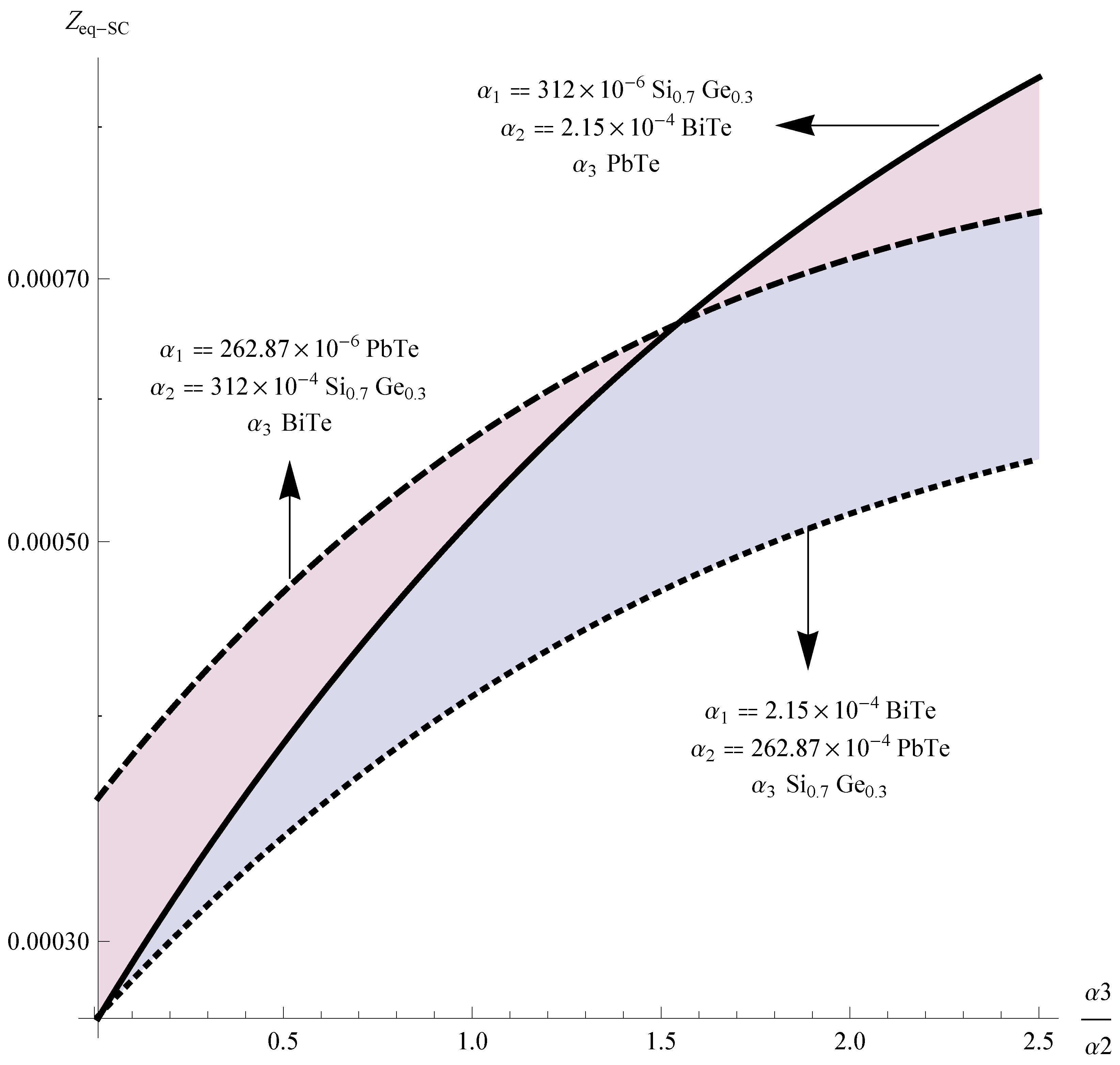
Figure 5.
vs. the ratio , maintaining y constant.
Figure 5.
vs. the ratio , maintaining y constant.
The
Figure 5 corresponds for the SC-TES case, it is noteworthy that the optimal value for
is the arrangement (SiGe, BiTe and PbTe).
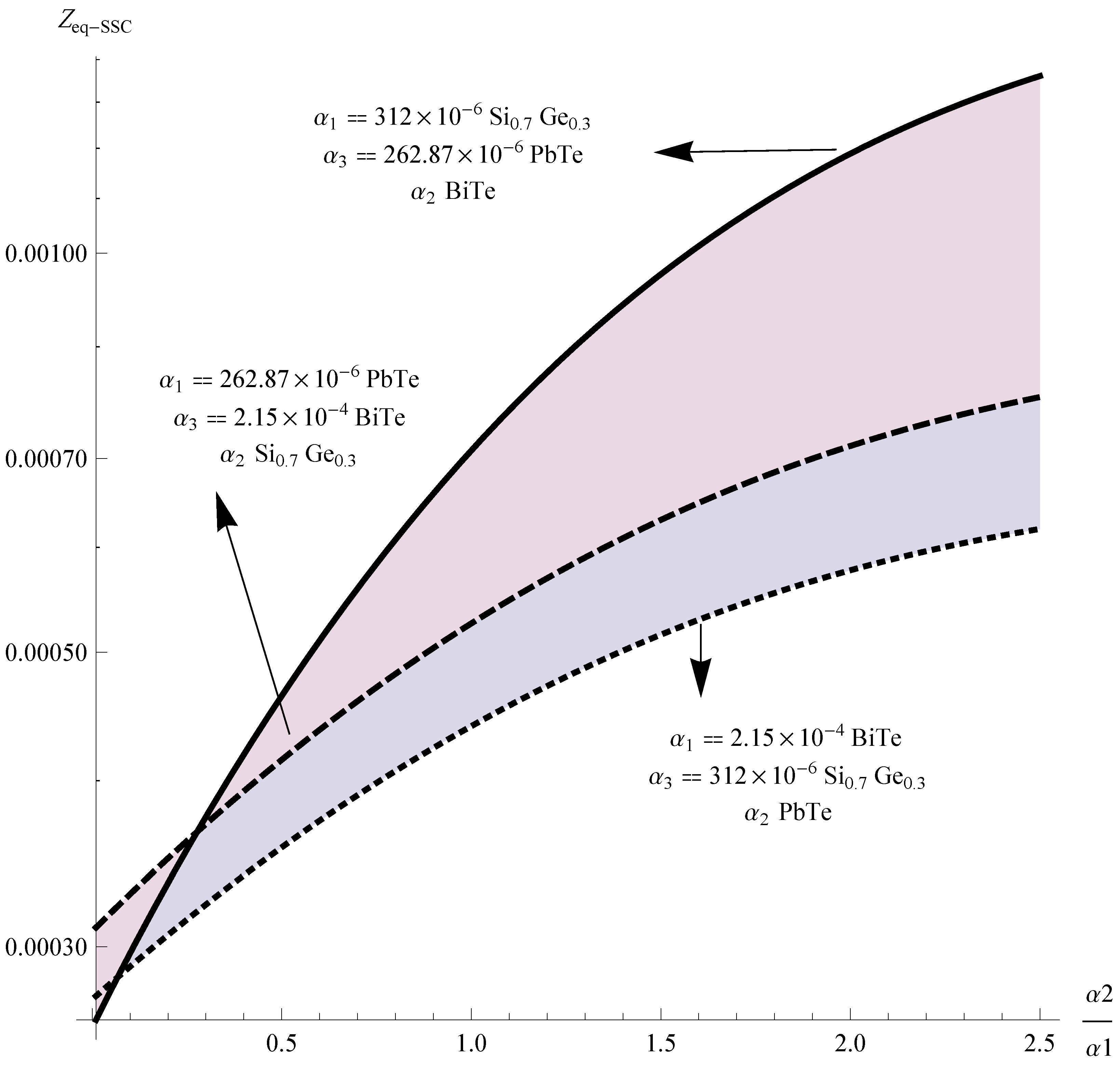
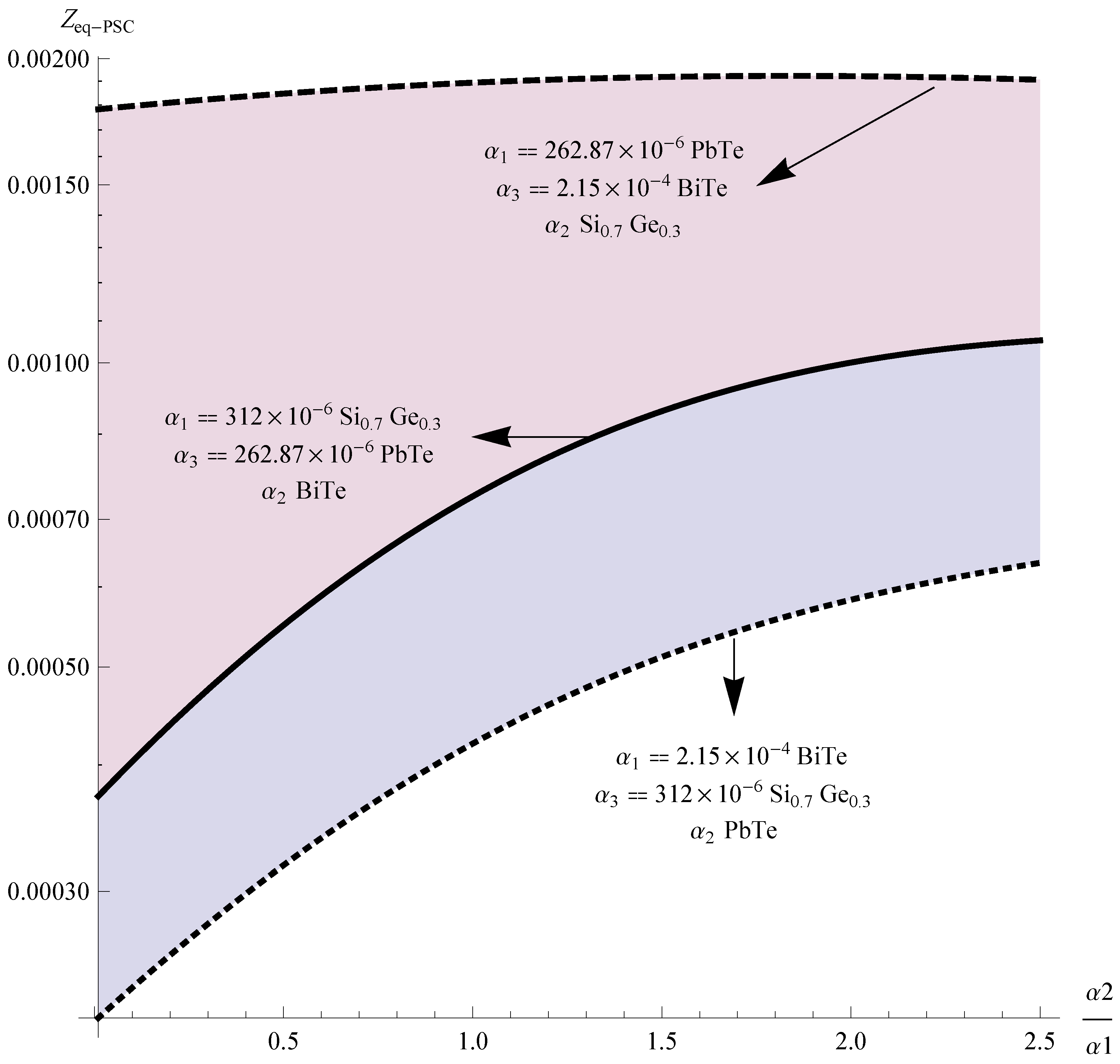
In the PSC-TES case, the optimal value for
is (PbTe, SiGe and BiTe); see
Figure 6.
Figure 6.
vs. the ratio, , maintaining and constant.
Figure 6.
vs. the ratio, , maintaining and constant.
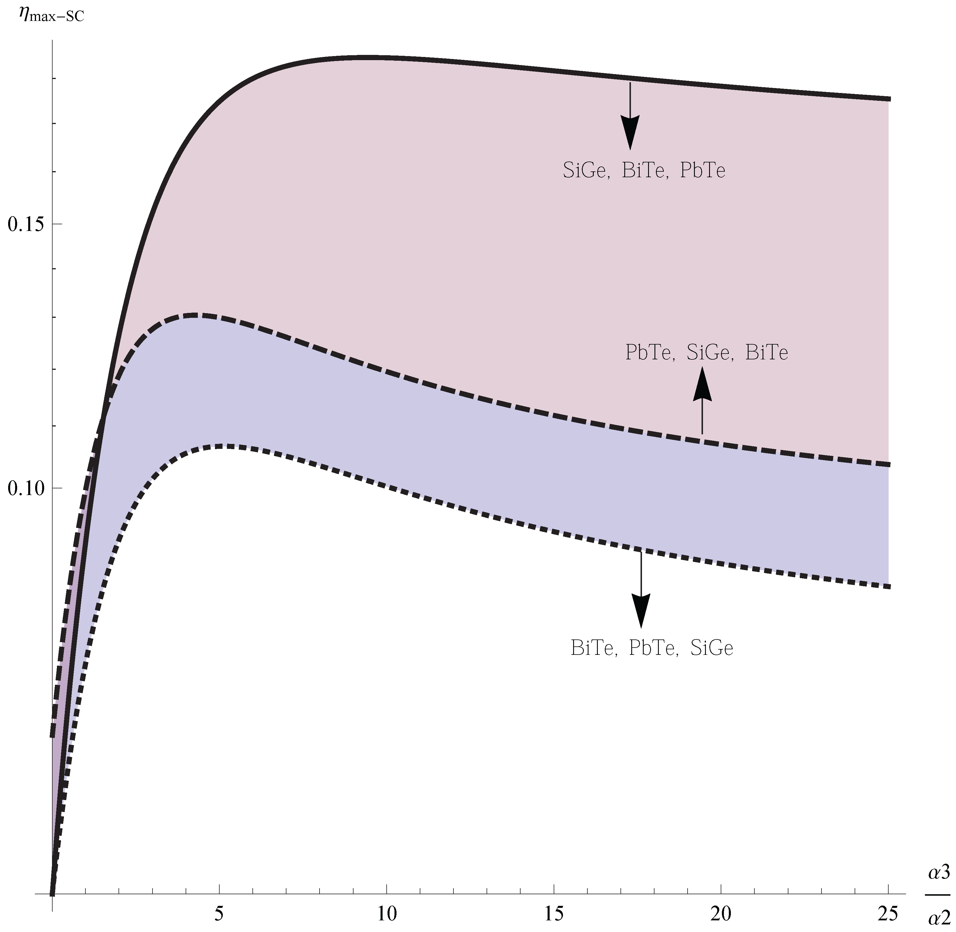
Finally, for the
case,
Figure 7, we have optimal values (SiGe, BiTe and PbTe). The arrangement (Bite, PbTE and SiGe) is the least optimal for the three connections.
Figure 7.
vs. the ratio, , maintaining , y, constant.
Figure 7.
vs. the ratio, , maintaining , y, constant.
3.1. Maximum Efficiency
The equivalent Figure of Merit has been formulated and calculated for each possibility. In order to justify the effectiveness of the equivalent Figure of Merit, the corresponding efficiency and out power has been formulated and calculated for each material and configuration.
The efficiency of a thermoelectric generator is governed by the thermoelectric properties of the generator materials and the temperature drop across the generator. The temperature difference,
, between the hot side,
, and the cold side,
, sets the upper limit of efficiency through the Carnot efficiency [
14].
For materials with thermoelectric properties
constant with respect to temperature, we evaluate the maximum efficiency in terms of the Figure of Merit [
27]:
where
with
is given by Equations (
13), (
29) and (
39), respectively.
Thus, we have for the
maximum efficiency of the SC-TES system:
For the
maximum efficiency of the PC-TES system:
and finally, we write the
maximum efficiency of the SSC-TES system:
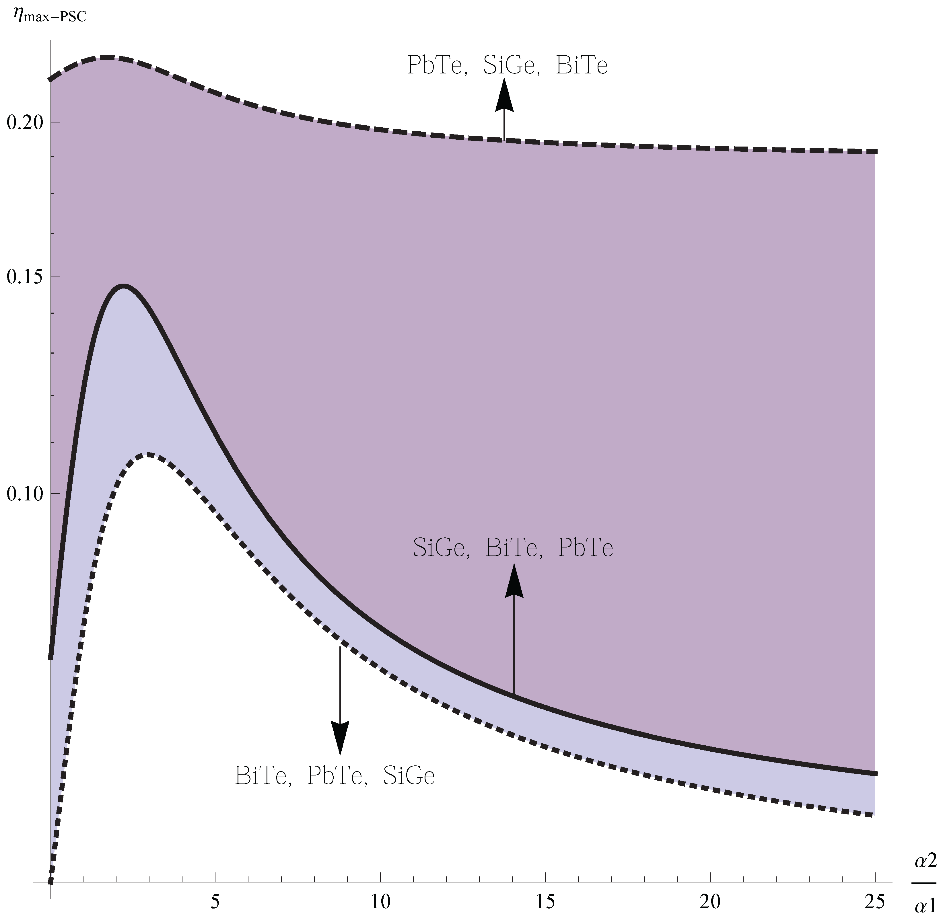
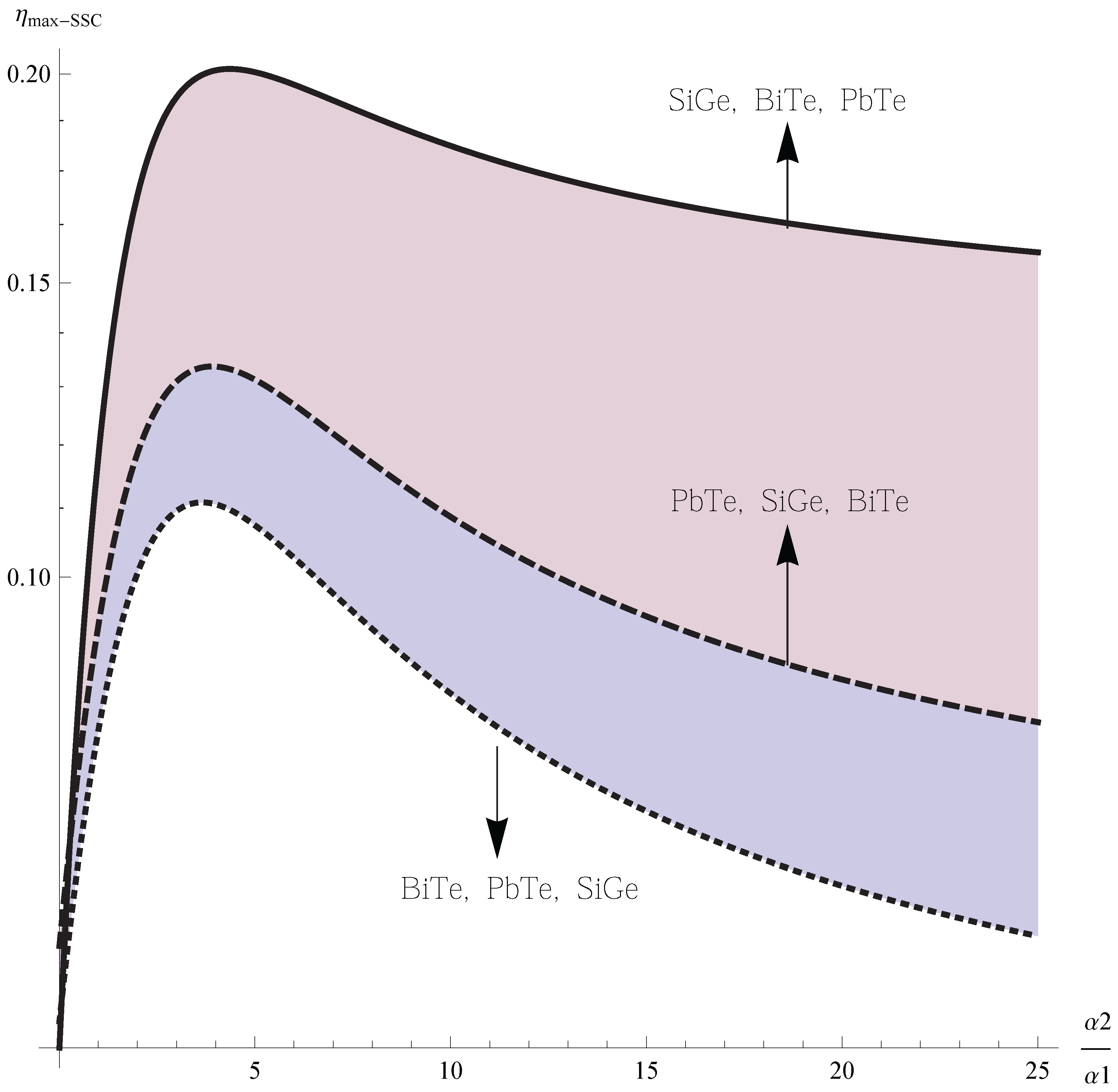
Our results are shown in
Figure 8,
Figure 9 and
Figure 10.
Figure 8.
vs. the ratio, .
Figure 8.
vs. the ratio, .
Figure 9.
vs. the ratio .
Figure 9.
vs. the ratio .
The
Figure 8,
Figure 9 and
Figure 10 show the typical behavior for the efficiency of TEM systems, and it is consistent with the behavior of the Figure of Merit of the TEM system. In fact, The experimental results show that the system efficiency is lower than the module efficiency and that the system performance may be modified [
28]. In our results, it is noticed that the overall efficiency of any thermoelectric system can become smaller than that of the TEMs from which the system is constructed.
It is very interesting to notice that TEM systems with a particular material, for example
and
, have reported an efficiency,
[
29], but our case shows that it is possible to get a different (higher or lower) efficiency with the same materials, but in different arrangements, in the same configuration. Recently, methodologies formulated on computational and analytical modeling [
30] derive the optimum efficiency and geometry of segmented, for example, for
PbT e, thermoelectric generators (TEGs) between
and
(
), and they show the influence of the configuration on the efficiency of the system. The behavior of the efficiency is analogous to our results.
Figure 10.
vs. the ratio, .
Figure 10.
vs. the ratio, .
4. Conclusions
Based on the outline of the theory of circuits, we have considered three types of TES, namely, SC-TES, PSC-TES and SSC-TES. For the first TES, we have used only one value of electrical current for the whole system. The PSC-TES and SSC-TES are composed of segmented TEM and conventional TEM thermally connected in parallel, but electrically connected in parallel and series, respectively. In addition, to get analytical results for the equivalent Figure of Merit in each case, also, we consider the impact of the arrangement of the TEM, with different thermoelectric material, in each whole system. This consideration was used to evaluate the equivalent Figure of Merit for each TES by varying the value of the ratios,
for
;
for
and
. The numerical results show that the optimal configuration, for the TES considered here, is the thermal and electrical connection in parallel with the arrangement (PbTe, SiGe and BiTe);
Figure 11. Also, we suggest in each case a practical thermoelectric device. As future work, we propose in the next analysis to take into account the effects of the length of the thermocouples and the area of contact between the components of the segmented generator. Also, we would like to mention that the analysis for the output power of these configurations will be analyzed elsewhere, because the comparison with realistic application to TEM systems requires special attention, as is shown by Apertet
et al. [
31]. We hope that the results of this present work provide a guide for the design of new thermoelectric generators.
Figure 11.
According to the
Table 1, the numeric values obtained for the Figure of Merit equivalents in each connection are displayed. The most optimum value corresponds to the thermal and electrical configuration in parallel.
Figure 11.
According to the
Table 1, the numeric values obtained for the Figure of Merit equivalents in each connection are displayed. The most optimum value corresponds to the thermal and electrical configuration in parallel.
Finally, It must be mentioned that the selected materials of the segments in segmented thermoelectric generators should be chemically compatible with minimal interfacial electrical and thermal resistances and an effective barrier to limit or eliminate mass diffusion across the interfaces [
20]. All of these effects have been neglected in this study, and of course, they will have a remarkable impact in practical devices. It is worth mentioning that, recently, the impact of junction temperature variation on the series circuits properties has been studied [
23]. On the other hand, special attention is required for the large systems with a great many TEMS, e.g., electrical connections of arrays of cascade thermoelectric modules (CTM) [
20]. A CTM is comprised of a top array of SiGe unicouples and a bottom array of unicouples of different, high thermoelectric materials. The top and bottom arrays are thermally, but not electrically, coupled and operate at the same nominal terminal voltage, but different load currents. Thus, the number of unicouples in the top and the bottom is different. These arrays include many effects for consideration. For example the top array of the CTM is optimized for maximum efficiency operation at nominal hot junction temperature. Thus, this work and others, e.g., [
23], are the first contributions to the study of large TEM systems.


