Maximum Power of Thermally and Electrically Coupled Thermoelectric Generators

 ,
,
Abstract
: In a recent work, we have reported a study on the figure of merit of a thermoelectric system composed by thermoelectric generators connected electrically and thermally in different configurations. In this work, we are interested in analyzing the output power delivered by a thermoelectric system for different arrays of thermoelectric materials in each configuration. Our study shows the impact of the array of thermoelectric materials in the output power of the composite system. We evaluate numerically the corresponding maximum output power for each configuration and determine the optimum array and configuration for maximum power. We compare our results with other recently reported studies.
1. Introduction
Efficient use of energy is one of the challenges that occupies both the field of sustainable energy research and industry. The energy sector is currently undergoing a process of transition that demands high energy efficiency, renewable energy sources and energy harvesting. An increase has been projected in energy consumption of approximately 40 percent for the year 2035 [1]. One of the main ways of meeting this need is the conversion of thermal energy to electric power, particularly from waste heat.
Recently, there has been a surge of research in the area of power harvesting. Energy harvesters use piezoelectric, smart and semiconductors materials. In fact, there exist both vibratory-based energy harvesters (moving parts) and thermoelectric energy harvesters (no moving parts) [2–7].
Thermoelectric generators are solid-state devices with no moving parts. They are silent, reliable and scalable, making them ideal for small, distributed power generation and energy harvesting [8].
Thermoelectric generator (TEG), based on the Seebeck effect, is a solid-state device that converts heat into electricity and is composed of two dissimilar semiconductors, and it operates between two heat reservoirs. This type of system has the advantage of generating electrical power, without using moving parts [9]. This feature makes it suitable for extreme conditions; plus, it needs little maintenance. Although, it still has low efficiency, compared with conventional power generation methods, approximately 5% – 15% [10,11]. The fact that TEGs can generate electric power using waste heat is already a great advantage.
TEGs have been used for electricity generation, and it is only in recent years that interest has increased regarding new applications of energy generation through thermoelectric harvesting. Thermoelectric energy harvesting has found some applications in developing thermoelectric energy harvesters to recover waste heat, for example, in vehicles [12].
A thermoelectric generator utilizes heat flow across a temperature gradient to power an electric load through the external circuit. The temperature difference provides the voltage (V = αΔT) from the Seebeck effect (Seebeck coefficient, α), while the heat flow drives the electrical current, which therefore determines the power output. The rejected heat must be removed through a heat sink [9].
Recent progress in the technological development of TEGs has relied on advances in material sciences: new materials and new techniques to produce specific structures have permitted the improvement of device performance through the characterization and optimization of the electrical and thermal transport properties (see the review of Di Salvio [13] and the recent one of Shakouri [14]).
Thermoelectric processes that occur in thermoelectric generators are subjected to the laws of thermodynamics. Treatment of these devices is accomplished within the framework of the thermodynamics of linear irreversible processes, because the thermoelectric effects (like the Seebeck effect) can be seen as the mutual interference of two irreversible processes occurring simultaneously in the TEG [15–19], which are governed by the equation:
It is observed that the heat flux, IQ, and electrical current, I, show a contribution, due both to the temperature difference and the potential difference. These contributions are functions of the properties of the thermoelectric materials. These properties are the Seebeck coefficient, α, the electrical resistance, R, and the thermal conductivity, K.
Using Equation (1), it is possible to obtain quantities, such as the efficiency, η, and the power, Pout, of the thermoelectric generator. For experimental purposes, power can be obtained by the measurement of electrical current supplied to the TEG. In this paper, we are interested in performing analytical calculations for the electric power that a thermoelectric system (TES), composed of different TEGs, delivers to a load resistance, Rload, in terms of Seebeck coefficient α, electrical resistance R and the thermal conductivity, K, of the TES.
The optimization of thermoelectric devices, in the thermodynamic framework, considering both its efficiency under different working conditions and irreversibilities inside inhomogeneous thermoelectric systems, is widely recognized by abundant studies on the subject [15–19].
It has been pointed out that the optimization of thermoelectric systems for energy conversion not only involves the improvement of the materials’ properties to enhance the so-called figure of merit, but also a strategic reflexion in device design [20]. Our calculations deal with practical cases that may serve as models to design actual devices. This work can be used as a guide for the design of new thermoelectric devices, which is an important matter.
This paper is organized as follows: in Section 2, we show the basic theory for the power of a thermoelectric generator. In Section 3, we calculate the output power and maximum power of coupled thermoelectric generators. In Section 4, we show and discuss our results, and finally, in Section 5, we give our conclusions.
2. Power of Thermoelectric Generators
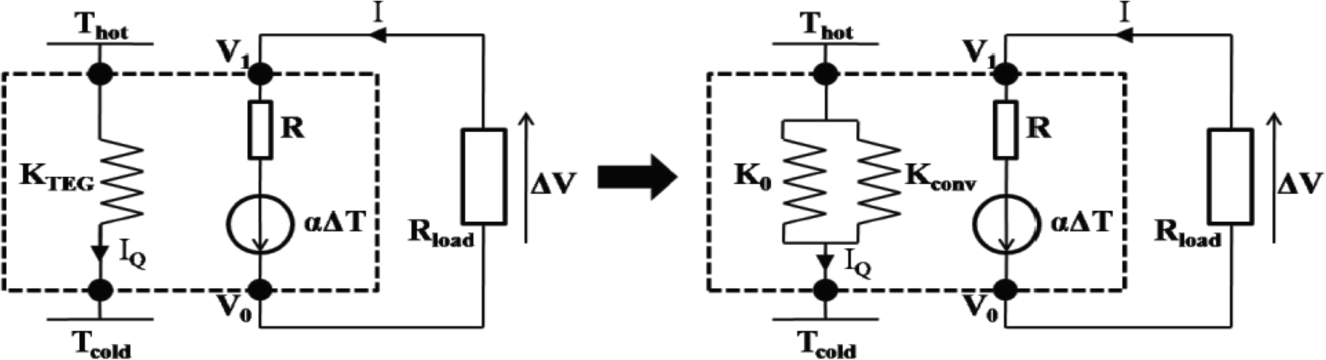
We follow the treatment proposed by Apertet et al. [17,21], in which a TEG is represented by a thermo-electric circuit. The behavior of the generator placed between two reservoirs at temperatures TH and TC is described relating the thermal (IQ) and electrical (I) currents to the temperature difference, ΔT, and the potential difference, ΔV, through the generator. The TEG is characterized by a isothermal electrical resistance, R, a thermal conductance, K0, under the open circuit condition and a Seebeck coefficient, α; see Figure 1.
For the case of a thermoelectric generator connected to a load resistor, Rload, the power delivered to Rload is given by the following equation [21],
where we now define the load ratio m = Rload/R.
The load resistance, Rload, which maximizes the output power, is obtained by equating to zero the derivative with respect to Rload. The value obtained is Rload = R. Thus, the maximum power is given by,
3. Thermoelectric Generators Coupled Thermally and Electrically
Based on the model presented in Section 2, the electrical power and the maximum power delivered by systems composed of thermoelectric modules (conventional and segmented) is calculated in terms of equivalent amounts, i.e., the equivalent Seebeck coefficient (αeq) and equivalent electrical resistance (Req). We only show the corresponding quantities for the configurations that are analyzed in this section, because the details of its derivation are showed by Vargas-Almeida et.al. [22].
Thus, we use in our analysis Equations (2,3) in terms of αeq y Req, namely,
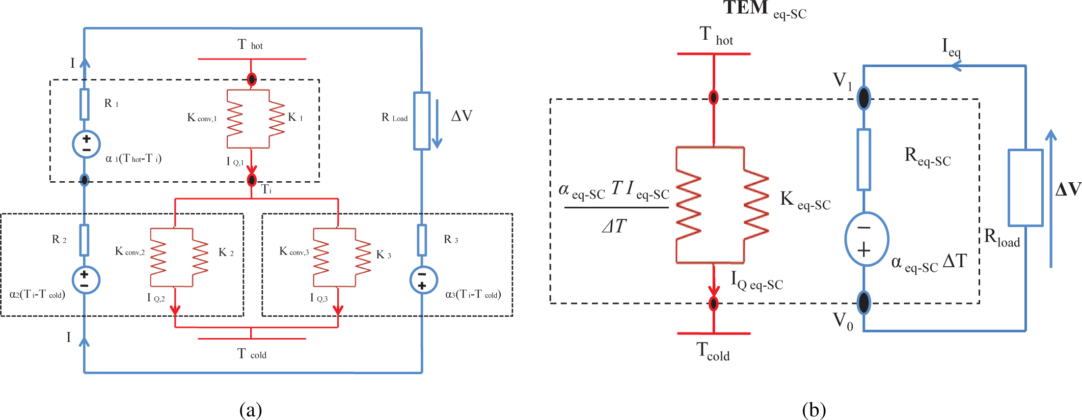
3.1. Two-Stage Thermoelectric System Connected in Series (SC-TES)
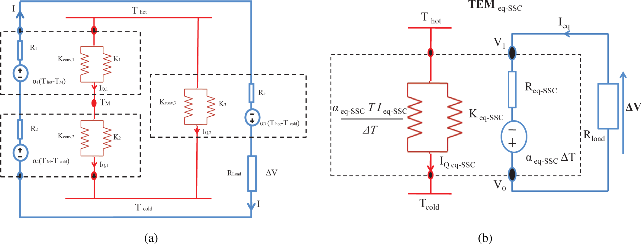
The first configuration considered is a two-stage thermoelectric system (TES) composed of three TEMthermally and electrically connected in series (SC-TES) [22]. The schematic of this system is shown in Figure 2. Each of the TEMs is characterized by its internal electrical resistance, Ri, thermal conductance under the open electrical circuit condition, Ki, and its Seebeck coefficient, αi, where i can be one, two or eq, as appropriate. All these coefficients are supposed constant. The whole system is subjected to a temperature difference, ΔT = Thot − Tcold, and its average temperature is T.
The corresponding equivalent quantities for these configurations are (1) The Seebeck coefficient series equivalent,
and (2) the electrical equivalent series resistance,
where,
Thus, substituting Equations (6)–(8) in Equation (4), the electrical power delivered by the system to the load resistance, Rload, is given by,

and the maximum power is given by,

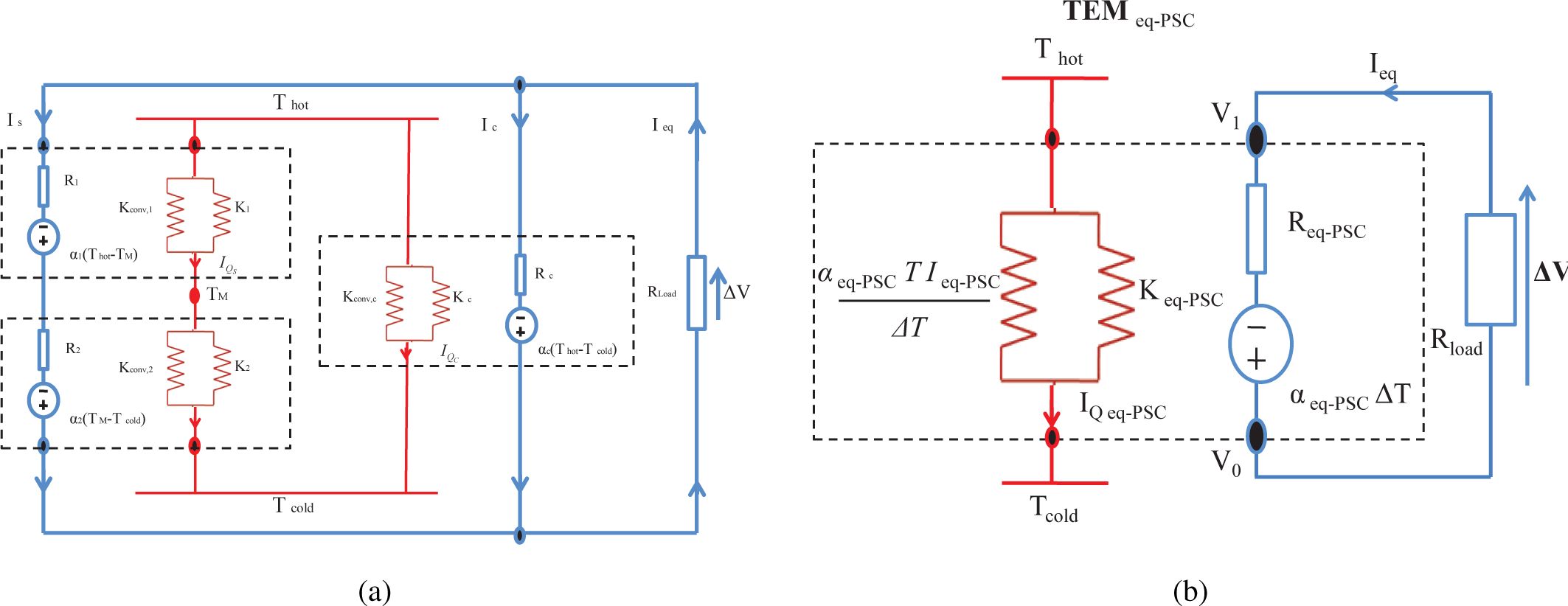
3.2. Segmented-Conventional Thermoelectric System in Parallel (PSC)
In this section, we consider a TES system, which is composed of a segmented TEM and a conventional TEM. These TEMs are thermally and electrically connected in parallel (PSC-TES), as is shown in Figure 3; see [22].
The corresponding equivalent Seebeck coefficient is given by,
where:
and the electrical resistance equivalent,
where Rc is the internal electrical resistance of the conventional TEM and Rs is the electrical resistance of the segmented TEM:
and
Substituting Equations (11) and (13) in Equation (4), the output power for this configuration is given by,

and using Equations (11) and (13) and Equation (5), the maximum power of this system obtained is,

3.3. Mixed Segmented-Conventional Thermoelectric System (SSC-TES)
In this case, we have considered a thermoelectric system (SSC-TES) composed of a segmented TEM and a conventional TEM, but they are thermally connected in parallel and electrically connected in series [22]; see Figure 4.
The corresponding equivalent Seebeck coefficient is given by,
and the electrical resistance equivalent,
where,
Thus, we have for the output power of the SSC-TES system,

and for the maximum power for the SSC-TES system,

In the following section, we show the power curves for each of the configurations of this system.
4. Results and Discussion
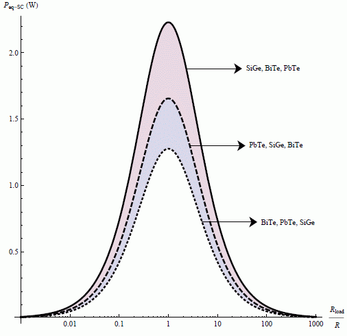
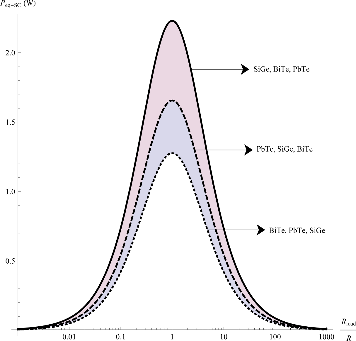
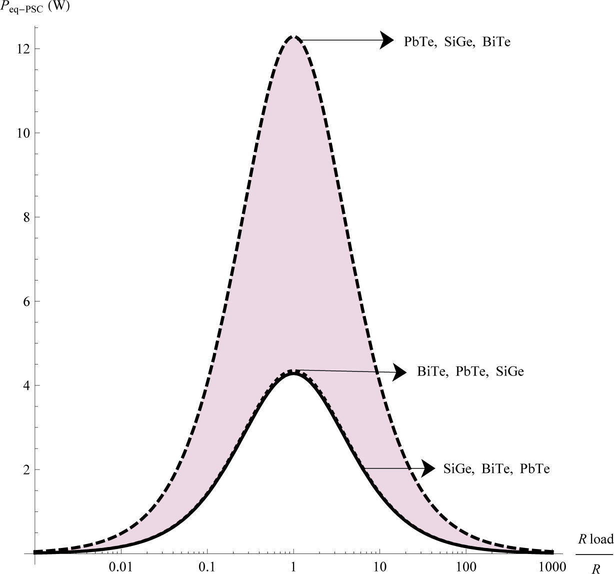
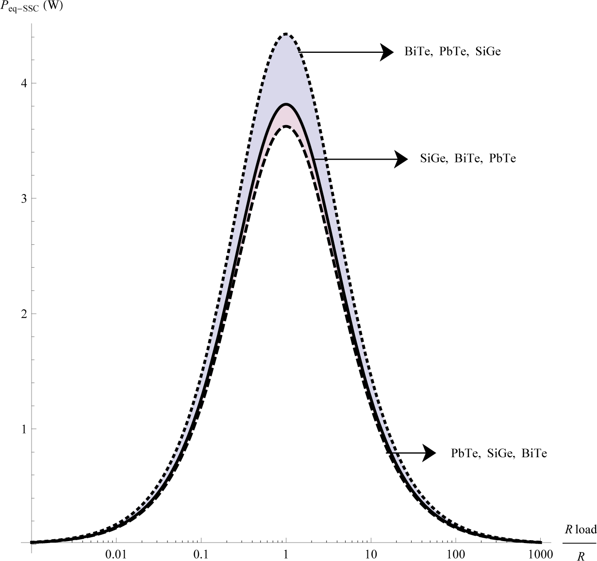
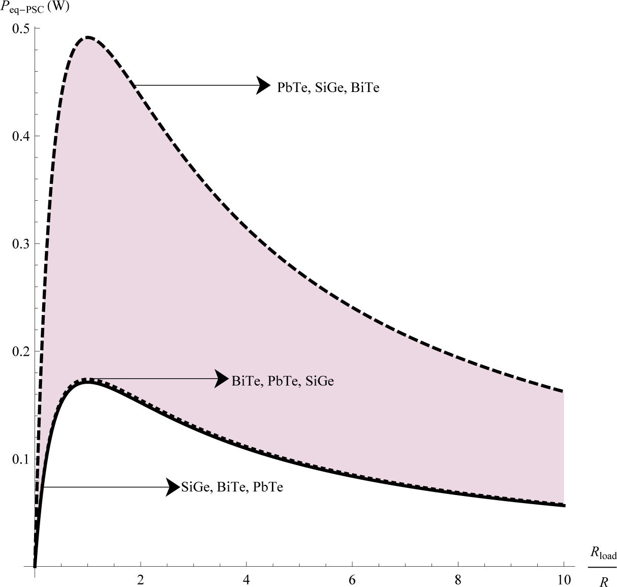
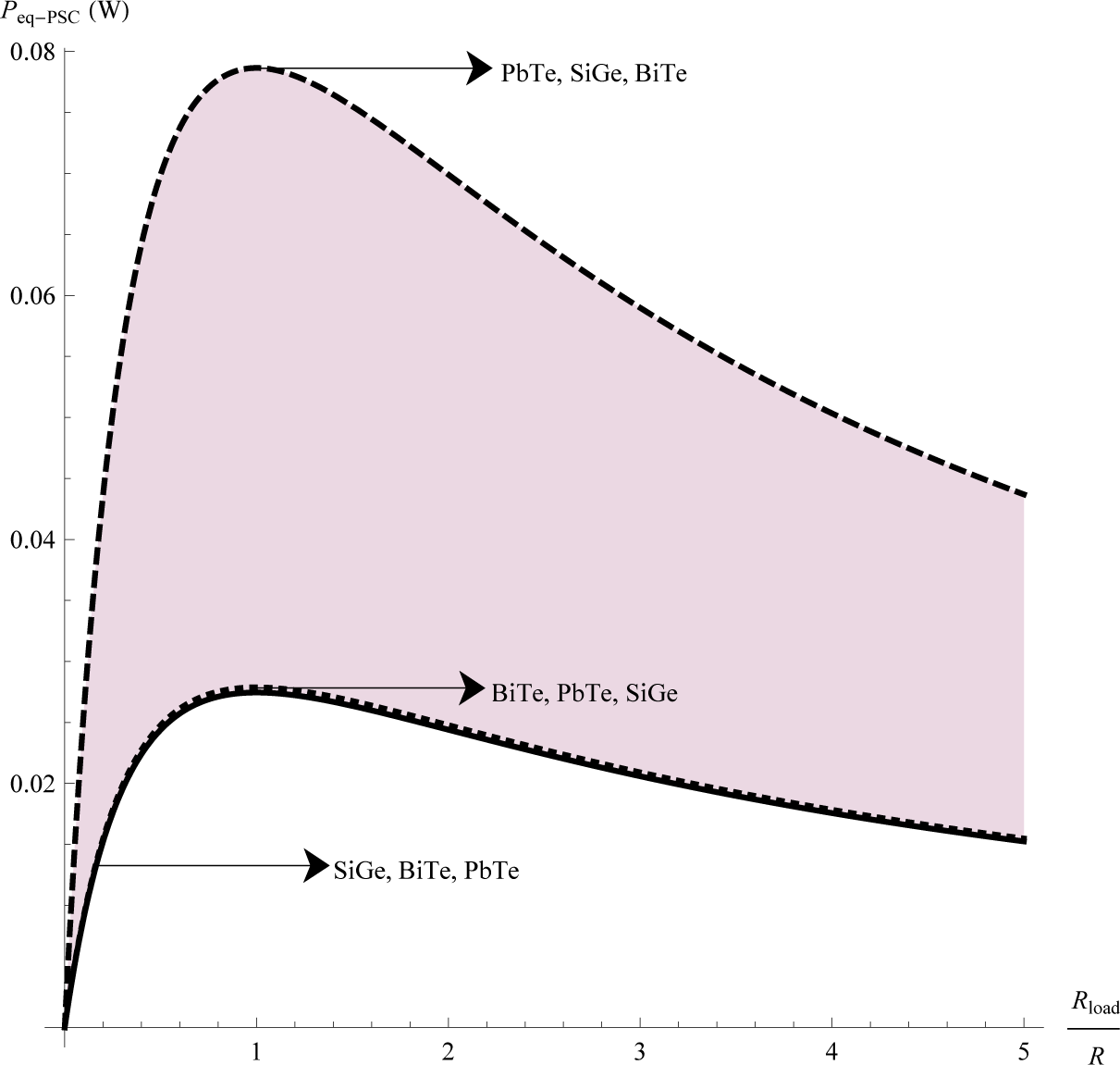
We show the behavior of the electrical output power delivered by each configuration of the TES. For this purpose, we have selected the following materials, BiTe, PbTe and SiGe. For showing the impact of the array of the thermoelectric materials in the output power of the TES, we consider different arrays for each configuration, in which we change cyclically the positions the three materials (one material for each module) throughout the whole system. Thus, we consider the following arrays, (BiTe, PbTe, SiGe), (PbTe, SiGe, BiTe) and (SiGe, BiTe, PbTe). Our results are given by Figures 5, 6 and 7, which show the output power as a function of the ratio between the electrical resistance of the load and the electrical resistance of the thermoelectric system .
Notice that each figure provides the highest output power value for one of the three arrays of the TES. These results show that the output power of the TES depends both on the configuration and the arrays of thermoelectric materials. Furthermore, our results show that, in the case of the PSC system with array (PbTe, SiGe, BiTe), maximum power is generated. This result is consistent with the results obtained by Vargas-Almeida et.al. [22], while for the SC and SSC systems, lower values for the output power are shown.
The behavior of the output power for each array of equivalent TES is consistent with the results obtained by Apertet et.al. [19].
Finally, The maximum power as a function of the equivalent amounts were numerically calculated for each of the three arrays of the system discussed above; see Table 1.
Table 1 shows that the system that delivers the lowest power corresponds to TES, whose thermoelectric modules are electrically and thermally connected in series, which reaches the smallest value in the array (BiTe, PbTe, SiGe); while the maximum value of the output power is obtained by the TES composed of a segmented and a conventional module, thermally and electrically connected in parallel, with PbTe, SiGe, BiTe arrays. Considering the mixed system SSC, it must be noted that its values for output power are between the minimum and maximum values obtained for the previous two TES. We show the consistency of our results with other works reported for different numerical values for a TES. We choose the PSC system with array (PbTe, SiGe, BiTe), which delivers the highest power, for comparing it with other studies reported. In an analytical electrothermal model developed and validated using experimental measurements, Abdelkefi et.al. [23], study the performance and validation of thermoelectric energy harvesters. Using their experimental values for the temperature difference ΔT = 20K, we obtain Figure 8. This last Figure 8 is consistent with that obtained by Abdelkefi, see Figure 6 in [23].
Another comparison is made with the works of Nemir et.al. [24] and Apertet et al. [25], which consider a temperature difference ΔT = 80K and an order of magnitude of 10−3 for electrical resistances; Figures 9 and 10 show qualitative behavior similar to the graphs shown in [24] and [25], respectively.
5. Conclusions
In this work has been evaluated the electrical power delivered by a TES composed of thermoelectric modules. The particular aspects of this TES are combined conventional and segmented thermoelectric modules, in different configurations, namely, series (SC), parallel (PSC) and mixed (SSC) configurations. We have shown the impact of the arrays of the modules with different thermoelectric materials. Our results show the impact in the output power of the TES of both the configuration and the arrays of thermoelectric materials. We find that the PSC system with the array (PbTe, SiGe, BiTe) delivers the highest power of all possible combinations; this is due to the type of thermal and electrical connection and also to the array of materials used for each module. We suggest that this work could lead to a new scheme for the design of composite thermoelectric systems. Figures 8 and 10 show the consistency of our results with other works, because they exhibit a behavior qualitatively similar to results reported in other recent studies [23–25].
Acknowledgments
This work was supported in part by Instituto Politecnico Nacional (IPN) grant PIFI-20140647-IPN Mexico (Miguel Angel Olivares-Robles). Alexander Vargas-Almeida and Pablo Camacho-Medina acknowledge Consejo Nacional de Ciencia y Tecnologia-Mexico for financial support.
Author Contributions
Miguel Angel Olivares-Robles supervised, processed and analyzed the results of this paper and wrote the paper. Pablo Camacho-Medina and Alexander Vargas-Almeida contributed to the calculations of this paper. Both authors contributed to the initial motivation of the problem, to research and to the writing. Both authors read and approved the final manuscript. Francisco Solorio-Ordaz helped in the analysis with constructive discussions, read and commented on the manuscript.
Conflict of Interest
The authors declare no conflict of interest.
References
- Energy Supply and Demand, Available online: http://www.chevron.com/globalissues/energysupplydemand (accessed on 17 February 2014).
- Anton, S.R.; Sodano, H.A. A review of power harvesting using piezoelectric materials (2003–2006). Smart Mater. Struct 2007. [Google Scholar] [CrossRef]
- Cook-Chennault, K.A.; Thambi, N.; Sastry, A.M. Powering MEMS portable devices—A review of non-regenerative and regenerative power supply systems with special emphasis on piezoelectric energy harvesting systems. Smart Mater. Struct 2008, 17, 043001. [Google Scholar]
- Abdelkefi, A.; Najar, F.; Nayfeh, A.H.; Ayed, S.B. An energy harvester using piezoelectric cantilever beams undergoing coupled bending–torsion vibrations. Smart Mater. Struct 2011, 20, 115007. [Google Scholar]
- Erturk, A.; Vieira, W.G.R.; de Marqui, C.; Inman, D.J. On the energy harvesting potential of piezoaeroelastic systems. Appl. Phys. Lett 2010, 96, 184103. [Google Scholar]
- Abdelkefi, A.; Nuhait, A. Modeling and performance analysis of cambered wing-based piezoaeroelastic energy harvesters. Smart Mater. Struct 2013, 22, 095029. [Google Scholar]
- Dai, H.L.; Abdelkefi, A.; Wang, L. Piezoelectric energy harvesting from concurrent vortexinduced vibrations and base excitations. Nonlinear Dyn 2014. [Google Scholar] [CrossRef]
- Snyder, G.J. Energy Harvesting Technologies; Springer: London, UK, 2009; Chapter 11; p. 325. [Google Scholar]
- Thermoelectric Generators, Available online: http://www.ecs.dtu.dk/english/Research/Thermoelectric-generators (accessed on 30 January 2014).
- Bitschi, A. Direct heat to electricity conversion. In Modelling of Thermoelectric Devices for Electric Power Generation; ETH Zurich: Zurich, Switzerland, 2009; Chapter 1; p. 13. [Google Scholar]
- Shawwaf, A. Optimization of the electric properties of thermoelectric generators. In Lund University Department of Automatic Control; Lund University: Lund, Sweden, 2010; Chapter 1; p. 1. [Google Scholar]
- Snyder, G.J. Small Thermoelectric Generators. Interface 2008, 17, 54–56. [Google Scholar]
- Di Salvio, F.J. Thermoelectric cooling and power generation. Science 1999, 285, 703–706. [Google Scholar]
- Shakouri, A. Recent Developments in Semiconductor Thermoelectric Physics and Materials. Annu. Rev. Mater. Res 2011, 41, 399. [Google Scholar]
- Ouerdane, H.; Goupil, C.; Apertet, Y.; Abbout, A.; Michot, A. A linear nonequilibrium thermodynamics approach to optimization of thermoelectric devices. In Thermoelectric Nanomaterials; Koumoto, K., Mori, T., Eds.; Springer: London, UK, 2013; pp. 323–351. [Google Scholar]
- Apertet, Y.; Ouerdane, H.; Goupil, C.; Lecoeur, Ph. Efficiency at Maximum Power Of Thermally Coupled Heat Engines. Phys. Rev. E 2012, 85, 041144. [Google Scholar]
- Apertet, Y.; Ouerdane, H.; Goupil, C.; Lecoeur, Ph. Thermoelectric internal current loops inside inhomogeneous systems. Phys. Rev. B 2012, 85, 033201. [Google Scholar]
- Apertet, Y.; Ouerdane, H.; Goupil, C.; Lecoeur, Ph. Irreversibilities and efficiency at maximum power of heat engines: The illustrative case of a thermoelectric generator. Phys. Rev. E 2012, 85, 031116. [Google Scholar]
- Apertet, Y.; Ouerdane, H.; Goupil, C.; Lecoeur, Ph. Internal Convection in Thermoelectric Generator Models. J. Phys. Conf 2012, 395, 012103. [Google Scholar]
- Rowe, D.M. Thermoelectrics Handbook: Macro to Nano; CRC Press: Florida, FL, USA, 2006. [Google Scholar]
- Goupil, C.; Seifert, W.; Zabrocki, K.; Muller, E.; Snyder, G.J. Thermodynamics of thermoelectric phenomena and applications. Entropy 2011, 3, 1481–1517. [Google Scholar]
- Vargas-Almeida, A.; Olivares-Robles, M.A.; Camacho-Medina, P. Thermoelectric System in Different Thermal and Electrical Configurations: Its Impact in the Figure of Merit. Entropy 2013, 15, 2162–2180. [Google Scholar]
- Abdelkefi, A.; Alothman, A.; Hajj, M.R. Performance analysis and validation of thermoelectric energy harvesters. Smart Mater. Struct 2013, 22, 095014. [Google Scholar]
- Nemir, D.; Beck, J. On the Significance of the Thermoelectric Figure of Merit Z. J. Electron. Mat 2010, 39, 1987–1901. [Google Scholar]
- Apertet, Y.; Ouerdane, H.; Glavatskaya, O.; Goupil, C.; Lecoeur, Ph. Optimal working conditions for thermoelectric generators with realistic thermal coupling. Europhys. Lett 2012, 97, 28001. [Google Scholar]


| TEM 1 | TEM 2 | TEM 3 | Pmax–eq–SC | Pmax–eq–PSC | Pmax–eq–SSC |
|---|---|---|---|---|---|
| BiTe | PbTe | SiGe | 1.27618 | 4.34854 | 4.42523 |
| PbTe | SiGe | BiTe | 1.65563 | 12.2877 | 3.62461 |
| SiGe | BiTe | PbTe | 2.22968 | 4.28067 | 3.81606 |
© 2014 by the authors; licensee MDPI, Basel, Switzerland This article is an open access article distributed under the terms and conditions of the Creative Commons Attribution license (http://creativecommons.org/licenses/by/3.0/).
Share and Cite
Camacho-Medina, P.; Olivares-Robles, M.A.; Vargas-Almeida, A.; Solorio-Ordaz, F. Maximum Power of Thermally and Electrically Coupled Thermoelectric Generators. Entropy 2014, 16, 2890-2903. https://doi.org/10.3390/e16052890
Camacho-Medina P, Olivares-Robles MA, Vargas-Almeida A, Solorio-Ordaz F. Maximum Power of Thermally and Electrically Coupled Thermoelectric Generators. Entropy. 2014; 16(5):2890-2903. https://doi.org/10.3390/e16052890
Chicago/Turabian StyleCamacho-Medina, Pablo, Miguel Angel Olivares-Robles, Alexander Vargas-Almeida, and Francisco Solorio-Ordaz. 2014. "Maximum Power of Thermally and Electrically Coupled Thermoelectric Generators" Entropy 16, no. 5: 2890-2903. https://doi.org/10.3390/e16052890