
Thermodynamic Analysis of a Waste Heat Driven Vuilleumier Cycle Heat Pump

Department of Power Engineering, North China Electric Power University, Baoding 07100, China
*
Author to whom correspondence should be addressed.
Entropy 2015, 17(3), 1452-1465; https://doi.org/10.3390/e17031452
Submission received: 29 January 2015
/
Revised: 13 March 2015
/
Accepted: 17 March 2015
/
Published: 20 March 2015
(This article belongs to the Special Issue Exergy: Analysis and Applications)
Abstract
:A Vuilleumier (VM) cycle heat pump is a closed gas cycle driven by heat energy. It has the highest performance among all known heat driven technologies. In this paper, two thermodynamic analyses, including energy and exergy analysis, are carried out to evaluate the application of a VM cycle heat pump for waste heat utilization. For a prototype VM cycle heat pump, equations for theoretical and actual cycles are established. Under the given conditions, the exergy efficiency for the theoretical cycle is 0.23 compared to 0.15 for the actual cycle. This is due to losses taking place in the actual cycle. Reheat losses and flow friction losses account for almost 83% of the total losses. Investigation of the effect of heat source temperature, cycle pressure and speed on the exergy efficiency indicate that the low temperature waste heat is a suitable heat source for a VM cycle heat pump. The selected cycle pressure should be higher than 100 MPa, and 200–300 rpm is the optimum speed.
1. Introduction
The energy crisis and environmental pollution are two of the world’s major problems [1,2]. Utilization of waste heat is a better way to combat these problems, for this method not only supplies more energy, but also simultaneously reduces the environmental pollution [3]. The amount of waste heat is huge. For example, the energy consumption in China during 2013 was 3.75 billion tons coal equivalent, and the overall energy conversion efficiency is about 72.3% [4], which means the waste heat is over1 billion tons coal equivalent. However, how to access and use this waste energy is a tough problem.
Heat pump technology is recognized as the most efficient way to utilize the waste energy. The coefficient of performance (COP) of an electric or mechanical driven heat pump is always greater than 1. In some cases, such as when high temperature waste heat sources are available, heat driven heat pumps will be more preferable. Absorption, adsorption and steam ejection are the most common types [5]. In general, the COP of a double effect absorption heat pump would be greater than 1, up to 1.56. The COP of adsorption is typically under 0.7, and even lower for steam ejection technology. The Vuilleumier (VM) cycle is also a heat activated closed gas cycle. It can utilize thermal energy, such as solar energy, isotope radioactivity, waste heat, etc. Experimental COP can reach 1.61, which is the highest among heat driven heat pump technology [6].
The VM cycle was patented by Rudolph Vuilleumier in 1918 [7]. This cycle has many advantages, such as fewer moving parts, a closed cycle, making it easier to control the pollution, potential higher COP, lower noise, lower mechanical friction and usefulness for distributed energy systems with small power output [8–12]. This cycle can also be applied in the cryogenic field [13,14]. Unfortunately, disadvantages always exist along with advantages. The cylinder volumes are not isothermal but nearly adiabatic. Even if the heat exchangers and the regenerators are perfect, the COP will be lower than for the Carnot cycle because the mean temperature in the cylinder volumes differs from the temperature in the heat exchanger brine. For a cooling cycle based on the VM cycle, the temperature difference between the two cylinder volumes is often smaller than the change of temperature in the cylinder volumes themselves, and the COP for the cooling cycle is thus seriously reduced. Another disadvantage is the specific output is low. For a desirable heat output the machine must be large, and therefore rather expensive.
The first application of the VM cycle heat pump in the room temperature field was in 1989 by Carlsen. He designed a natural gas driven VM cycle heat pump with helium as refrigerant for residence heating. The heating capacity output is 7.5 kW, and the COP reaches 1.62 [15]. Later he developed a 20 kW gas fired VM cycle heat pump [16]. Kuehl transformed the crankshaft driven VM heat pump into the free piston driven type [17,18]. Lee analyzed the influence of structure on the performance of VM heat pump, and the results show that the structure of the regenerator has a significant effect on the performance [19]. Finkelstein [20], Sekiya [21,22] and Kawajiri[23] have presented analyses of system performance. Xie [24] carried out research on the influence of binary mixtures on the regenerator of a VM heat pump.
Up to now, no work has related the second law of thermodynamics to a VM cycle heat pump. To comprehensively understand the VM cycle heat pump, an exergy analysis is carried out along with an energy analysis in this paper to evaluate the application of a VM cycle heat pump in waste heat utilization.
2. VM Cycle Heat Pump
2.1. Configuration
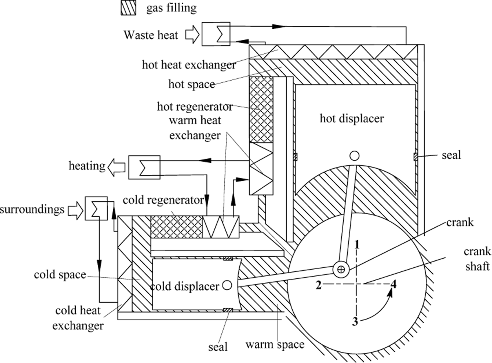
Figure 1 shows the construction schematic of a waste heat driven VM cycle heat pump. The basic VM cycle heat pump contains two cylinders, namely a cold cylinder and a hot cylinder. Each cylinder has a displacer which performs reciprocating motion inside the cylinder. A seal device is used between the displacer and the cylinders for anti-leakage purposes. The hot and cold displacers are driven by a crankcase with a connecting rod.
As shown in Figure 1, the space between the hot displacer and the top of the hot cylinder is called hot space, while the cold space is between the cold displacer and the top of the cold cylinder. The space between the cold displacer, hot displacer and the crankshaft is called warm space. A cold regenerator is placed between the cold space and warm space, while a hot regenerator is between the warm space and hot space. The regenerators work as a heat storage system when the working fluid flows between spaces.
The input high temperature waste heat is absorbed by the hot heat exchanger, mixed with low temperature heat from the surroundings which is absorbed by cold heat exchanger, providing heating from the warm heat exchanger for domestic purposes.
2.2. Working Process
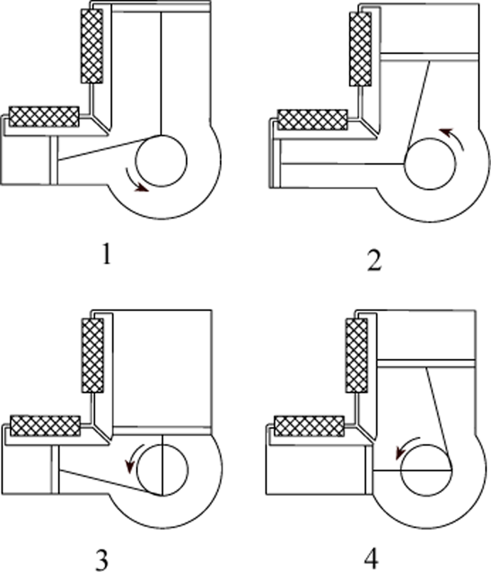
The working process for a VM cycle heat pump is shown in Figure 2. The positions of the starting points are shown in Figure 1.
The cycle starts at point 1, and the whole process is illustrated as follows:
- Process 1–2: the crankcase rotates counterclockwise, making the crankshaft push the hot displacer to the bottom of the hot space, while the cold displacer moves to the top of the cold space. During this process, the hot space volume increases, and the cold space volume decreases. As the hot displacer moves to the bottom, the working fluid from the warm space is heated to close to the hot space temperature (Th) by filling materials when going through the hot regenerator, and then the working fluid goes into the hot space. The working fluid in the cold space is pushed by the cold displacer to the warm space, where it is heated to near the warm space temperature (Ta) by the filling material in the cold regenerator. Both the temperature and the pressure of the VM cycle heat pump increase rapidly. Output heat is supplied by the warm heat exchanger in the warm space.
- Process 2–3: the crank moves from left to the bottom. The hot displacer still goes to the bottom of hot space. Meanwhile the cold displacer leaves the top to the bottom of cold space. The volumes of both are increasing. During this process, the working fluid in the warm space is cooled to nearly the cold space temperature (Tc) by the filling material in the cold regenerator, and then enters the cold space. Gas in the hot space absorbs heat from high temperature waste heat through the hot heat exchanger, while the cold space is absorbing heat from the low temperature surroundings using the cold heat exchanger.
- Process 3–4: the crank rotates from bottom to right. The hot displacer leaves the bottom of the hot space to the top, and the cold displacer keeps moving to the bottom of the cold space. The hot space volume decreases, while the cold space volume keeps increasing. During this process, the working fluid in the hot space is pushed into the warm space by the hot displacer and cooled to nearly the warm space temperature (Ta) by the filling materials when crossing the hot regenerator. The gas temperature decreases, and the pressure also drops.
- Process 4–1: the crank moves from right to the top. The hot displacer moves to the top of the hot space, and the cold displacer leaves the bottom to the top of cold space. The hot space volume decreases to nearly 0, and the cold space volume decreases continuously. During this process, gas in the hot space is cooled to nearly the warm space temperature (Ta) by the filling in the hot regenerator, then goes into warm space, with the pressure drop. A part of the gas in the cold space is heated to nearly the warm space temperature by the filling in the cold regenerator when it passes through the cold heat exchanger, and then returns to the warm space.
3. Thermodynamic Analysis
Simultaneous calculation and separate calculation are the two main methods to perform the thermodynamic analysis for a VM cycle heat pump [25]. In this paper, the separate calculation method based on an isothermal model is chosen. For the theoretical cycle, it assumes the following:
- Processes occurring in all spaces are isothermal, i.e. the temperature of the compression or the expansion process is stable.
- No losses occur in all the processes within the cycle, which means there is no heat transfer or flow resistance.
- The working fluid is considered as ideal gas.
3.1. Working Fluid
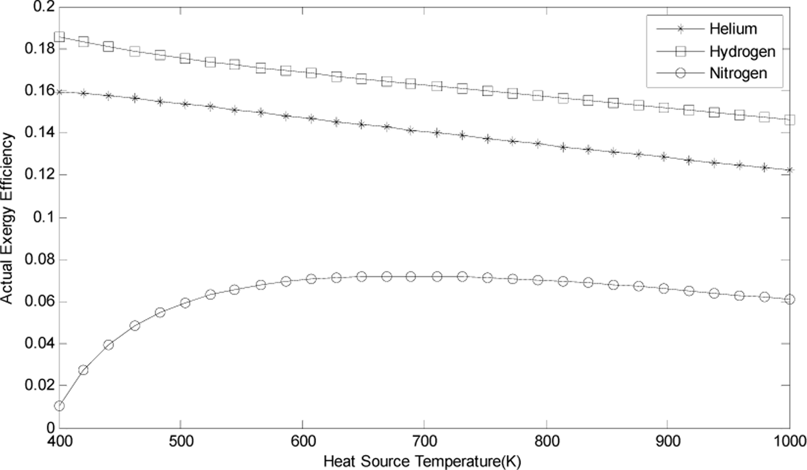
The common working fluids adopted by the VM cycle heat pump are helium, hydrogen and nitrogen. As the VM cycle heat pump is a closed gas cycle, these working fluids are always in gas phase without any phase change. The properties of these working gases deviate from those of the ideal gas, so the different working gases adopted in a VM cycle heat pump have different system performance.
Generally hydrogen is the best working gas, but hydrogen is too active and it can easily explode when leaks occurs. Figure 3 shows that the differences in the thermodynamic performance of a VM cycle heat pump using hydrogen or helium as the working gas are small, and greater than when nitrogen is used as working gas. For both safety and performance concerns, helium is selected as the working gas for the VM cycle heat pump. All calculations carried out in this paper are based on helium as refrigerant. Some properties of helium are listed in Table 1.
3.2. Calculation Parameters
Table 2 gives the parameters needed for calculation, including constructional parameters and working conditions of the VM cycle heat pump.
The heating output will be supplied as a radiator system or floor heating system. Radiator systems are more common, but the literature shows that floor heating systems are more comfortable. Floor heating systems have higher Predicted Mean Vote (PMV) and low vertical temperature differences. Floor heating systems also have energy saving advantages, as the system supply temperature is normally under 60 °C (typically it is 55 °C). The system return temperature is set at 35 °C.
3.3. Equations for the Energy and Exergy Analyses
All the equations used in this paper are referred to literature [8].
Heat absorbed by the cold space Qco, referred to as the refrigerating capacity, can be defined as:
where pav is the average space pressure; Vco is the max volume of the cold space; n denotes the speed of the crank rotation; δ is the pressure parameter and θ is the phase angle.
Heat transferred from the waste heat in hot space Qh is:
where τco denotes the temperature ratio at the cold side,
; τh is the temperature ratio at the hot side,
.
Qa is the heat output for heating purposes from the warm space:
For an actual VM cycle heat pump, there exist lots of irreversible losses, such as reheat losses, flow friction losses, shuttle losses, pumping losses, heat conduction losses, leakage losses and so on. Reheat loss ΔQR represents the heat transfer losses in the heat exchanger of the regenerator caused by temperature differences, wall effects, temperature swings of materials, etc.:
where cp is the specific heat at constant pressure; M0 is the average mass flux through the regenerator; ηR is the regenerator efficiency, typically ηR =0.98.
Flow friction loss ΔQf refers to the pressure losses when the working gas passes through the regenerator, heat exchanger and ducts:
where ΔP is the pressure drop.
In a VM cycle heat pump, displacers have the same axial temperature distribution as the cylinders. Due to the reciprocating motion of the displacers, there exists a temperature difference between the displacers and cylinders. This heat transfer loss is called shuttle loss ΔQsh:
where Fs is a correction factor, which generally has a value of 0.52–0.73; λ is the thermal conductivity, Dco is the diameter of the cold cylinder; Z is the displacer stroke; δ is the radial clearance between the displacer and cold cylinder; L is the displacer length.
Because of the temperature difference, the working gas entering each space will result in an extra heating load. This is called pumping loss ΔQp:
where Pmax is the maximum pressure during the cycle; Pmin is the minimum pressure during the cycle; Zp is the gas compressibility factor.
In an actual VM cycle heat pump, the length of the rod of displacers is short, resulting in heat conduction losses. The heat conduction loss ΔQd is the sum of the wall conduction loss ΔQdw and the filling material conduction loss ΔQdm:
The wall conduction loss ΔQdw is:
where A is the cross-sectional area.
Filling material conduction loss ΔQdm can be expressed as:
There is also a temperature difference between the VM cycle heat pump and surroundings. This heat loss is called heat dissipation loss, ΔQl. We can take account for 5% of the Qco, so the total losses of a VM cycle heat pump are:
The theoretical and practical aspects of thermodynamics are most relevant to energy and exergy analysis. Exergy analysis provides an alternative and illuminating means of assessing and comparing processes and systems rationally and meaningfully. Exergy analysis can assist in improving and optimizing designs.
The specific exergy flow of the working gas or water is evaluated as follows:
where h is the enthalpy; s is the entropy; and the subscript zero indicates properties at the reference (dead) state (i.e., at P0 and T0).
Here we suppose that the temperature T of the waste heat is constant, then the thermal exergy of waste heat at heat flow Q transferred to the VM cycle heat pump is:
The exergy efficiency COPex [26] is generally expressed as the ratio of total exergy output to total exergy input and is written as follows:
where “output” refers to “net output” or “product” or “desired value”, and “input” refers to “driving input” or “fuel”. For a VM cycle heat pump, the output is the heating, with Tout at 55 °C and Tin at 35 °C, the input is the waste heat and/or the heat from the surrounding different than the dead state. Exergy efficiency for a VM cycle heat pump can then be written as follows:
3.4. Calculation Results
Table 3 shows the calculation results for the theoretical VM cycle heat pump. The assumptions of the theoretical VM cycle heat pump are as stated before, which include no irreversible losses. With the parameters in Table 3, the results show the theoretical exergy efficiency is 0.23.
Table 4 is the result of the actual process. The actual exergy efficiency is 0.15, much lower than the theoretical value of 0.23. The reason is the losses generated during the actual process. Among these losses, reheat loss and flow friction loss account for a large proportion of the total loss, almost 83%.
3.5. The Influence of Parameters on Exergy Efficiency
The theoretical and actual exergy efficiencies calculated above are based on the given parameters. Some parameters may affect the exergy efficiency greatly, while others only have a slight effect. The following is the analysis result of the effect of some parameters on the exergy efficiency for the calculated prototype VM cycle heat pump.
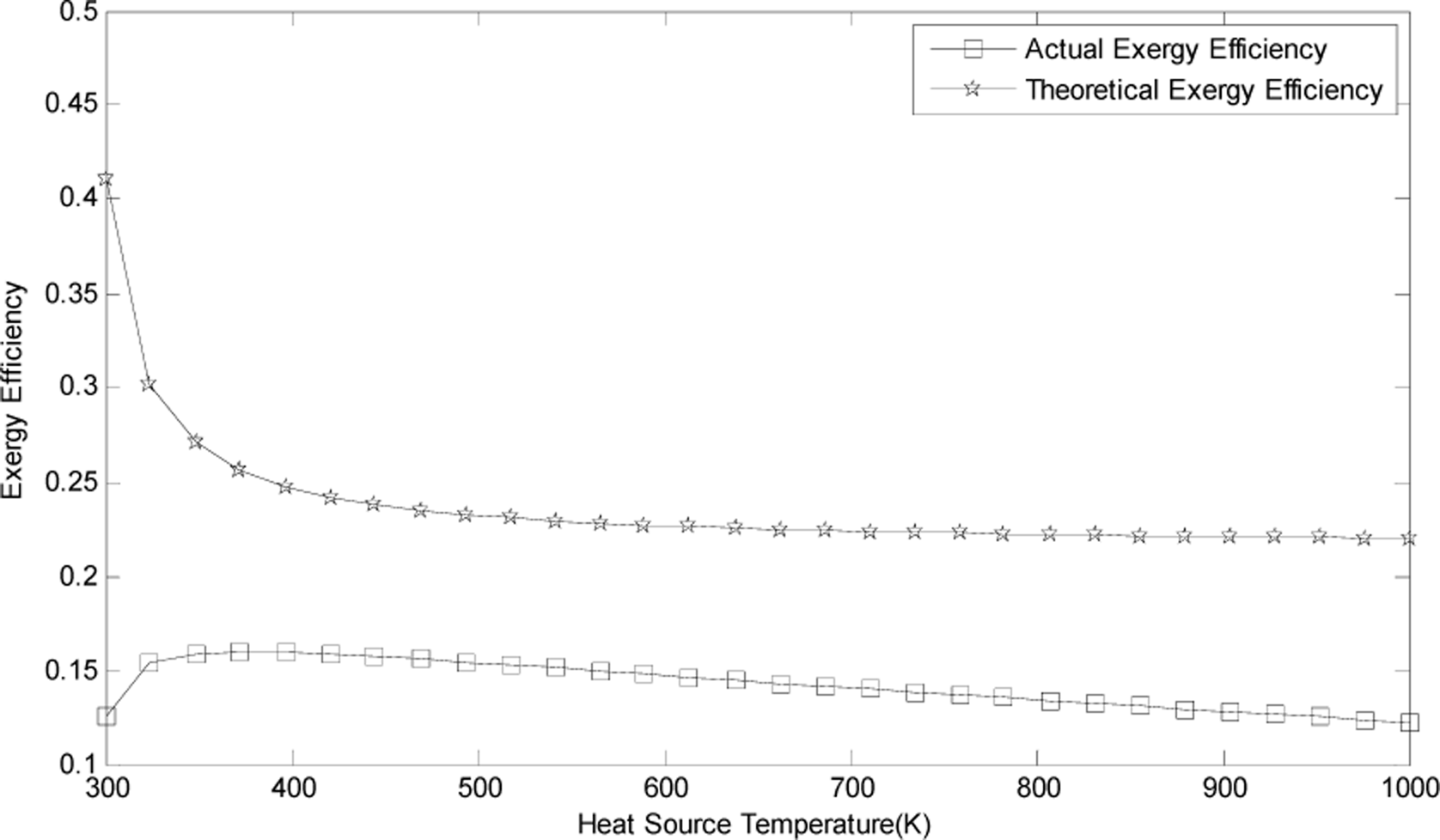
Figure 4 shows the influence of heat source temperature on the exergy efficiency. As the temperature of the waste heat increases, the theoretical exergy efficiency decreases, while the actual first increases then decreases, reaching a maximum at the point of 370K. This means that we do not need to have much higher temperature waste heat since lower heat source temperature results in higher exergy efficiency. For most waste heat the temperature is under 600K, so a VM cycle heat pump can be used for waste heat utilization.
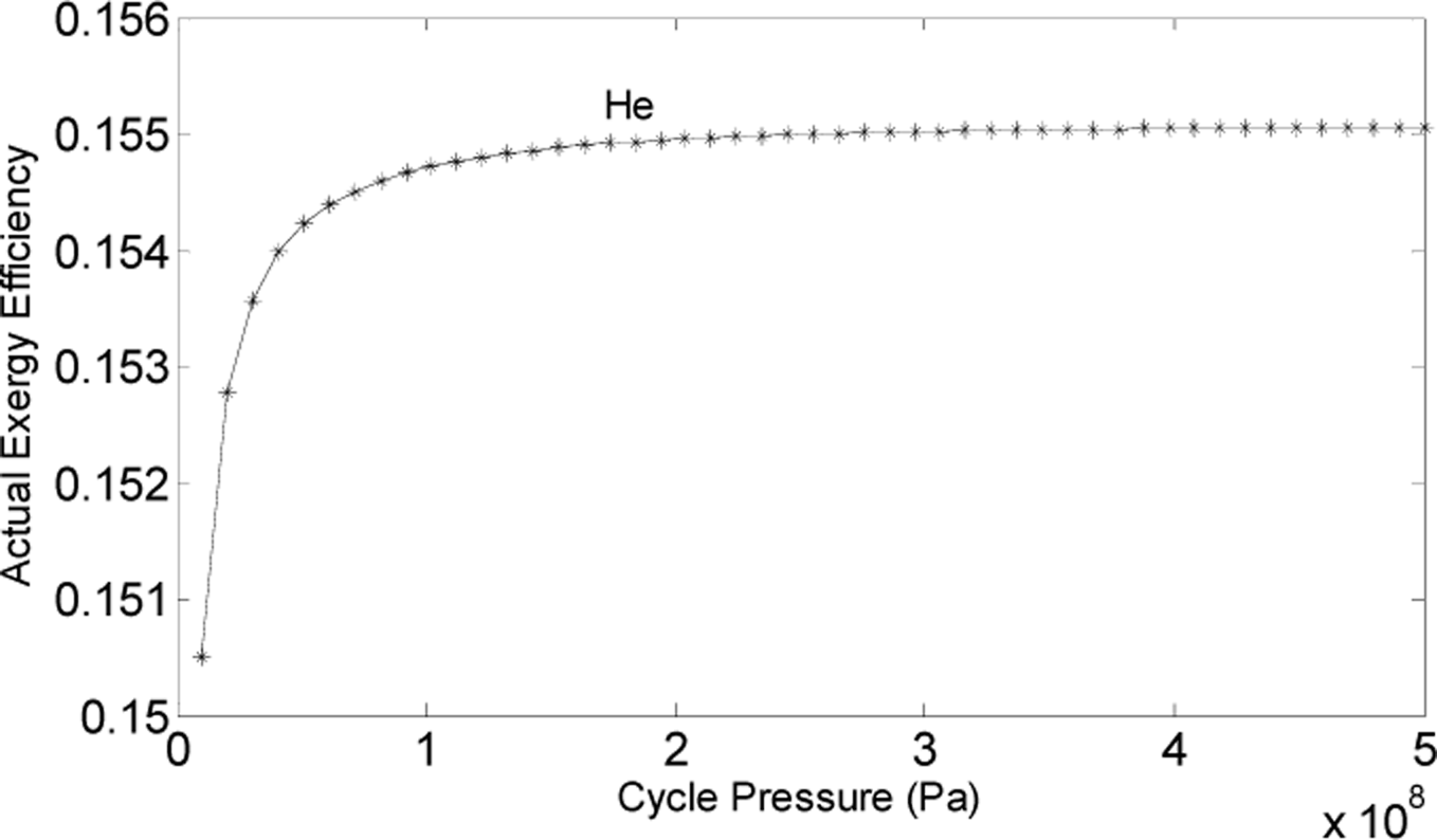
The influence of cycle pressure on actual exergy efficiency is shown in Figure 5. As the pressure increases, the actual exergy efficiency also increases. After the cycle pressure reaches 100MPa, the exergy efficiency becomes stable. For most cases, the optimum pressure is hard to reach, so it can be treated as a reference to obtain higher performance.
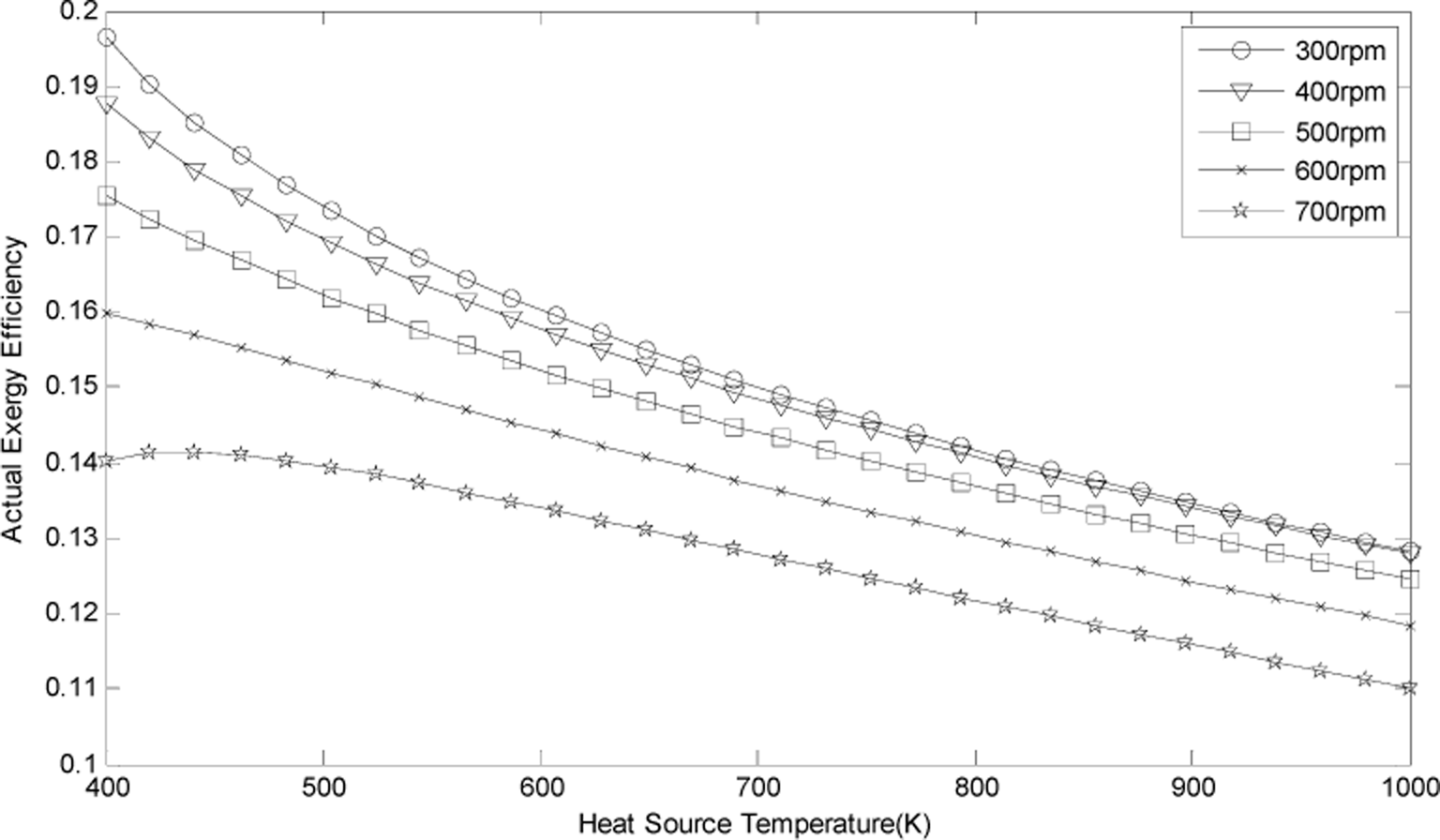
Figure 6 presents the influence of speed and heat source temperature on actual exergy efficiency. A faster speed leads to lower exergy efficiency, while the amplitude of the exergy efficiency decrease increases.
4. Conclusions
In this paper, analyses of the theoretical and actual cycle of a VM heat pump are presented. Besides, the influence of some parameters on exergy efficiency is given. The conclusions are as follows:
- According to the calculation results, the theoretical and actual exergy efficiency are 0.23 and 0.15, separately. Reheat losses and flow friction losses account for almost 83% of the total loss.
- As the temperature of waste heat increases, the theoretical exergy efficiency decreases, while the actual one first increases then decreases, reaching a maximum at the point of 370K. Low temperature waste heat under 600K temperature is more suitable as the driving heat source of a VM cycle heat pump.
- The cycle pressure and speed also have great influence on the exergy efficiency. The selected cycle pressure should be higher than 100MPa, and 200–300rpm is optimum for speed.
Acknowledgments
The project is supported by the Natural Science Foundation of Hebei Province (No. E2014502085).
Nomenclature
| D | Diameter (m) |
| Z | Stroke (m) |
| Φ | Volume phase angle (°) |
| L | Length (m) |
| δ | Clearance (m) |
| T | Temperature (K) |
| P | Pressure (Pa) |
| n | Rotational speed (rpm) |
| ω | Volume ratio |
| He | Helium |
| R | Universal gas constant (JK−1mol−1) |
| CP | Specific heat (Jkg−1K−1) |
| V | Volume (m3) |
| τ | Temperature ratio |
| Q | Heat quality (W) |
| θ | Pressure phase angle (°) |
| ψ | Porosity |
| D | Diameter (m) |
| A | Area (m2) |
| a | Specific heat transfer area (m2) |
| COP | Coefficient of performance |
| r | Hydraulic radius (m) |
| ρ | Density (kgm−3) |
| M | Mass flux (kgs−1) |
| ΔP | Pressure drop (Pa) |
| Fs | Correction factor |
| Δ | Heat loss (W) |
| Zp | Gas compressibility factor |
| COPex | Exergy efficiency |
| Subscripts | |
|---|---|
| co | Cold space |
| h | Hot space |
| a | Warm space |
| R | Regenerator |
| av | Average |
| max | Maximum |
| min | Minimum |
| m | Material |
| f | Flow |
| sh | Shuttle |
| p | Pumping |
| i | Ideal |
| e | Effective |
Author Contributions
Yingbai Xie proposed and designed the research; Xuejie Sun performed the calculations. Both authors jointly worked on deriving the results and wrote the paper. Both authors have read and approved the final manuscript.
Conflicts of Interest
The authors declare no conflict of interest.
References
- Grossman, P.Z.; Energy, Shocks. Crises and the Policy Process: A Review of Theory and Application. Energy Policy. 2015, 8, 56–69. [Google Scholar]
- Skouloudis, A.N.; Kassomenos, P. Combining Environment and Health Information Systems for the Assessment of Atmospheric Pollution on Human Health. Sci. Total Environ. 2014, 488–489, 362–368. [Google Scholar]
- Semkov, K.; Mooney, E.; Connolly, M.; Adley, C. Efficiency Improvement through Waste Heat Reduction. Appl. Therm. Eng. 2014, 70, 716–722. [Google Scholar]
- National Data. Available online: http://data.stats.gov.cn/workspace/index;jsessionid=0E028DD36CE5EEC4B0FDC6EB60547493?m=hgnd accessed on 13 March 2015.
- Dong, L.; Huang, H.; Kobayashi, N. Development of an all-in-one Type Adsorption Heat Pump for Heating Application. Int. J. Chem. React. Eng. 2011, 9, 18–24. [Google Scholar]
- Xie, Y.B.; Deng, X.D.; Zhao, J.H. Fuzzy Comprehensive Evaluation of System Performance for Vuilleumier Cycle Heat Pump Driven by Solar, Geo-thermal and Biomass Energy. Appl. Power Energy Technol. 2014, 8, 1080–1083. [Google Scholar]
- Vuilleumier, R. Method and Apparatus for Including Heat Change. U.S. Patent 1, 275, 507 1918. [Google Scholar]
- Bian, S. Cryogenic Refrigerator; China Machine Press: Beijing, China, 1990; pp. 56–57. [Google Scholar]
- ASHRAE, Engine-driven heating and cooling equipment. In ASHRAE Systems and Equipment Handbook; Machinery Industry Press: Beijing, China, 1981; pp. 54–65.
- Wu, Y. Refrigeration and Cryogenic Technology Principle; High Education Press: Beijing, China, 2007; pp. 26–33. [Google Scholar]
- Li, X. Refrigeration Principle and Equipment; Machinery Industry Press: Beijing, China, 2006; p. 39. [Google Scholar]
- Wang, R.; Ding, G.; Wu, J. Refrigeration Principles and Techniques; Science Press: Beijing, China, 2005; pp. 15–28. [Google Scholar]
- Rule, T.T.; Qvale, E.B. Steady-Stale Operation of the Idealized Vuilleumier Refrigerator. Adv. Cryog. Eng. 1969, 14, 343–352. [Google Scholar]
- White, R. Vuilleumier Cycle Cryogenic Refrigeration; Technical Report AFFDL-TR-76-17; Air Force Wright Aeronautical Laboratories, Wright-Patterson Air Force Base: Dayton, OH, USA, 1976. [Google Scholar]
- Carlsen, H. Development of a Gas Fired Vuilleumier Heat Pump for Residential Heating. Proceedings of the Intersociety Energy Conversion Engineering Conference, Washington, D.C., WA, USA, 6–11 August 1989; IEEE: New York, NY, USA, 1989; pp. 2257–2263. [Google Scholar]
- Carlsen, H. Development of a New 20 kW Gas Fired Heat Pump Based on the Vuilleumier Cycle. Proceedings of the 25th Intersociety Energy Conversion Engineering Conference, Reno, NV, USA, 12–17 August 1990; IEEE: New York, NY, USA, 1990; pp. 233–238. [Google Scholar]
- Kuhl, H.-D.; Schulz, S.; Thomas, B.; Carlsen, H. Conversion of a Crank-driven Vuilleumier Heat Pump into a Free Piston Machine. Proceedings of the Intersociety Energy Conversion Engineering Conference, Atlanta, GA, USA, 8–13 August 1993.
- Pfeffer, T.; Kuehl, H.-D.; Schulz, S.; Walther, C. Development and Experimental Investigation of New Concepts for Regenerators of Regenerative Gas Cycles-exemplary for Vuilleumier heat Pumps. Eng. Res. 2000, 65, 257–272. [Google Scholar]
- Lee, G.T.; Kang, B.H.; Yoo, H. Effects of Geometric Configuration on the Cooling Performance of a Vuilleumier Cycle Heat Pump. Proceedings of the Energy Conversion Engineering Conference, Washington, D.C., WA, USA, 11–16 August 1996; IEEE: New York, NY, USA, 1996; pp. 781–786. [Google Scholar]
- Finkelstein, T. Isothermal Sinusoidal Analysis of Balanced Compound Vuilleumier Heat Pumps. Proceedings of the Intersociety Energy Conversion Engineering Conference, San Diego, CA, USA, 3–7 August 1992.
- Sekiya, H.; Yamashita, I. Multisimulation Model for Stirling and Vuilleumier Cycle Machines. JSME Int. J. Ser. B Fluids Therm. Eng. 1993, 36, 383–390. [Google Scholar]
- Sekiya, H.; Kobayashi, K.; Fukuda, E. Numerical Analysis and Experimental Investigation of a Free Piston Vuilleumier Cycle Heat Pump. Proceedings of the 29th Intersociety Energy Conversion Engineering Conference, Washington, D.C., WA, USA, 7–11 August 1994.
- Kawajiri, K.; Honda, T.; Sugimoto, T. Study of Free Piston Vuilleumier Heat Pump (Performance Characteristics of Prototype Machine at Forced Vibration). Trans. Jpn Soc. Mech. Eng. Ser. B 1996, 62, 2430–2437. [Google Scholar]
- Xie, Y.B.; Wang, S.H.; Li, B.; Liu, Y. Influences of Binary Mixtures on the Regenerator of VM Cycle Heat Pump. Appl. Mech. Mater. 2011, 52–54, 249–254. [Google Scholar]
- Rios, P.A.; Smith, J.L., Jr. An Analysis of Stirling Cycle Refrigerator. Adv. Cryog. Eng. 1969, 14, 332–342. [Google Scholar]
- Ozcan, H.; Dincer, I. Thermodynamic Analysis of a Solar Driven Tri-generation System for Building Applications. In Progress in Exergy, Energy, and the Environment; Springer International Publishing: New York, NY, USA, 2014; pp. 169–180. [Google Scholar]
Figure 1.
Schematic of a Vuilleumier cycle heat pump.

Figure 2.
Working processes of a Vuilleumier cycle heat pump.

Figure 3.
The influence of working fluids on exergy efficiency.

Figure 4.
The influence of heat source temperature on exergy efficiency.

Figure 5.
The influence of cycle pressure on the actual exergy efficiency.

Figure 6.
The influence of speed and heat source temperature on actual exergy efficiency.


| Parameter | Symbol | Value |
|---|---|---|
| Working fluid | He | — |
| Universal gas constant | R | 8.314 J/(K·mol) |
| Specific heat | CP | 5.187×10³J/(kg·K) |
| Thermal conductivity | λ | 0.306W/(m·K) |
| Parameter | Symbolor Instruction | Value |
|---|---|---|
| Cylinder bore | Dco | 0.0699 m |
| Stroke | Z | 0.0312 m |
| Space phase angle | Φ | 90° |
| Displacer length | L | 0.04359 m |
| Displacer radial clearance | δ | 0.00015 m |
| Regenerator diameter | DR | 0.0226 m |
| Regenerator length | LR | 0.0226 m |
| Regenerator material | Stainless steel wire | — |
| Hot space temperature | Th | 553 K |
| Warm space temperature | Ta | 338 K |
| Cold space temperature | Tco | 263 K |
| Surrounding temperature | T0 | 273 K |
| Average temperature | 408 K | |
| Average pressure | Pav | 10.0×10⁶ Pa |
| Drive system | Single crank, Double-acting pistons drive | — |
| Rotational speed | n | 600 rpm = 10 Hz |
| Volume ratio | ω | 10 |
| Item | Symbol | Value |
|---|---|---|
| Stroke volume of cold space | Vco | 119.73×10⁻⁶ m3 |
| Temperature ratio | τ | 2.1 |
| Pressure phase angle | θ | 85.8° |
| Temperature ratio at cold side | τco | 1.3 |
| Temperature ratio at hot side | τh | 0.6 |
| Pressure factor | 0.2 | |
| Pressure ratio | Pmax/Pmin | 1.5 |
| Maximum pressure | Pmax | 12.4×10⁶ Pa |
| Minimum pressure | Pmin | 8.1×10⁶ Pa |
| Theoretical cooling of cold space | Qco | 4020.1 W |
| Theoretical heat consumption of hot space | Qh | 2948.7 W |
| Theoretical heat rejection of warm space | Qa | 6968.8 W |
| Theoretical exergy efficiency | COPex,i | 0.23 |
| Subject | Symbol | Value |
|---|---|---|
| Reheat loss | ΔQR | 1317.9 W |
| Flow friction loss | ΔQf | 1196.6 W |
| Shuttle loss | ΔQsh | 322.4 W |
| Pumping loss | ΔQp | 0.8 W |
| Wall heat conduction loss | ΔQdw | 6.7 W |
| Filling heat conduction loss | ΔQdm | 1.7 W |
| Heat conduction loss | ΔQd | 8.4 W |
| Leakage loss | ΔQl | 201.0 W |
| Total loss | ΔQ | 3046.9 W |
| Actual cooling | Qco,ac | 1497.3 W |
| Actual heat rejection | Qa,ac | 4769.1 W |
| Actual heat consumption | Qh,ac | 3271.8 W |
| Actual exergy efficiency | COPex,e | 0.15 |
© 2015 by the authors; licensee MDPI, Basel, Switzerland This article is an open access article distributed under the terms and conditions of the Creative Commons Attribution license (http://creativecommons.org/licenses/by/4.0/).
Share and Cite
MDPI and ACS Style
Xie, Y.; Sun, X. Thermodynamic Analysis of a Waste Heat Driven Vuilleumier Cycle Heat Pump. Entropy 2015, 17, 1452-1465. https://doi.org/10.3390/e17031452
AMA Style
Xie Y, Sun X. Thermodynamic Analysis of a Waste Heat Driven Vuilleumier Cycle Heat Pump. Entropy. 2015; 17(3):1452-1465. https://doi.org/10.3390/e17031452
Chicago/Turabian StyleXie, Yingbai, and Xuejie Sun. 2015. "Thermodynamic Analysis of a Waste Heat Driven Vuilleumier Cycle Heat Pump" Entropy 17, no. 3: 1452-1465. https://doi.org/10.3390/e17031452