1. Introduction
As is known, any scientific discipline serves and aims at understanding and describing these or those regularities and features of certain phenomena, situations, events caused by the existence of some real or thinkable objects that manifest themselves their specific properties [
1,
2]. Based on the considerations that the study of a new object, as a rule, generates a new scientific discipline as applied to Mechanics, the hierarchy of objects can be built. Successive complexity of objects studied by mechanics is shown in works [
1,
2,
3,
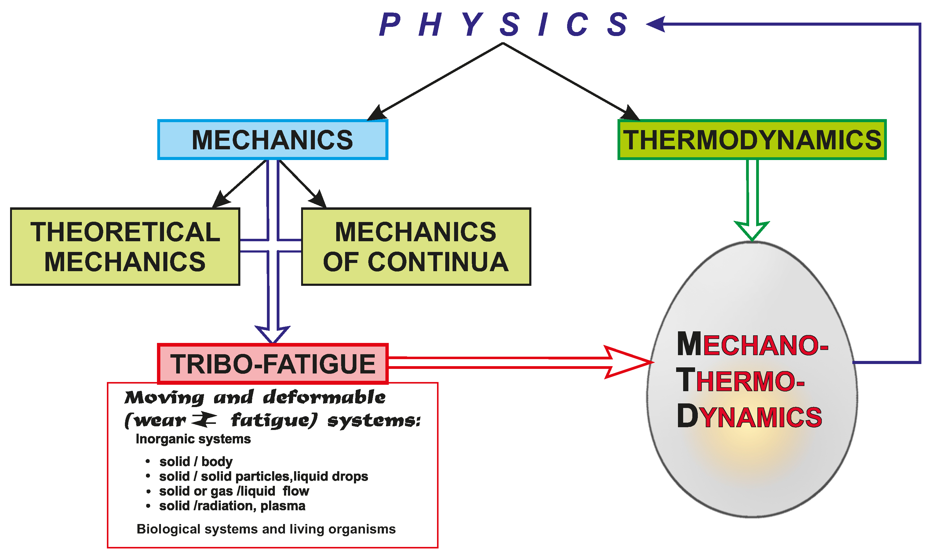
4]. The next new object is multiphase—
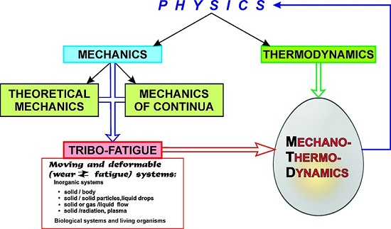
mechanothermodynamics system. Methods of mechanics alone are insufficient for its study as well as methods of thermodynamics alone.
These methods and models addressing coupled problems of both stress-strain states and energy states of the complex systems working under mechanical and thermodynamic loading are discussed in well-known monographs [
5,
6,
7,
8,
9,
10,
11]. The concepts of entropy and damage are important in order to construct models of the
mechanothermodynamical system.
Basic ideas about mechanical behavior of materials under the fracture process are discussed in [
9]. The work [
12] addresses the main aspects of Damage Mechanics as the branch of Fracture Mechanics and some of its applications. Fundamentals of Physical Mesomechanics of heterogeneous media that develops at the boundary of Continuum Mechanics, Physics of Plasticity and Strength of Materials and studies the stressed and damaged material at linked micro-, meso- and macro levels are given in [
13].
Constitutive relations for strain-induced damage in terms of thermodynamic consistency and also applications of Continuum Damage Mechanics to failures of mechanical and civil engineering components in ductile, creep, fatigue and brittle conditions due to thermomechanical loading are considered in [
14,
15]. The related problems of constructing theories of vibration and plasticity for steady-state vibrations in elastoplastic bodies are discussed in [
16].
The works [
17,
18] contain a concise review of basic continuum damage models, micromechanics of damage, kinetics of damage evolution and discuss the areas of further research. A general framework for the development of continuum damage models defined by yield and damage surfaces in stress space with consideration of the damage mechanisms (isotropic damage, cracking, etc.) which degrade the stiffness of the material is proposed in [
19]. A detailed experimental and theoretical study on the stress-based forming limit criterion during linear and complex strain paths is given in [
20]. A thermodynamic framework intended for modelling both friction and non-associated flow for geotechnical materials is presented [
21]. The papers [
22,
23] are dedicated to modelling of the large strain elastic–plastic deformation behavior of anisotropically damaged ductile metals. The formulation of the elasto-plastic-damage behavior of materials is introduced in [
24] within a thermodynamically consistent framework that uses functional forms of hardening internal state variables in both damage and plasticity. Paper [
25] proposes a damage theory in terms of kinematic, thermodynamic and kinetic coupling for polycrystalline material.
A microscopic damage model considering an ellipsoidal void that is able to change its shape is considered in [
26] for mixed-hardening materials. Results of experimental analysis of voids behavior in model materials using X-ray tomography are discussed in [
27,
28]. Analytical and scanning electron microscopy based study of void growth and change of shape under large plastic deformation is presented in [
29]. Phenomenological representation of anisotropic damage progression for porous ductile metals with second phases is described through mechanisms of void nucleation, growth and coalescence in [
30]. An analytical and computational mesoscopic models for the nucleation and interaction of microcracks near a macrocrack tip based on both the theory of elasticity and the theory of dislocations are presented in [
31]. The framework allowing the combination of plasticity and damage models of inelastic behaviour is proposed in [
32].
A damage evolution model based on thermodynamic theory is developed in works [
33,
34,
35,
36,
37,
38,
39,
40,
41,
42,
43,
44,
45,
46,
47,
48,
49,
50,
51,
52,
53,
54,
55,
56,
57,
58,
59,
60]. According to this model irreversible entropy production rate under loadings of different nature is considered as a single universal damage term—damage metric. In particular this model was used to predict damage evolution and viscoplastic behavior in polymer composites with imperfect interfacial bonds. A corresponding viscoplastic constitutive model was used to describe thermomechanical response of amorphous polymers below and above glass transition temperature. Method of numerical study of voids migration due to action of pulse electric current and thermal gradient solder joints was developed using entropy based damage criteria in order to characterize the mass transportation mechanism.
Recent advances in Tribology involve the use of the fundamental concepts of thermodynamic entropy. Significant accomplishments are reported in the works [
61,
62,
63] aimed at developing a unifying theory for friction and wear. The motivation of this study was a series of experimental investigation that appeared in an article [
63] and a pioneering theory on the science of degradation [
62]. Development of the thermodynamics of fatigue fracture as well as thermodynamically-based damage mechanics are reported in [
64,
65,
66].
In [
1,
67,
68,
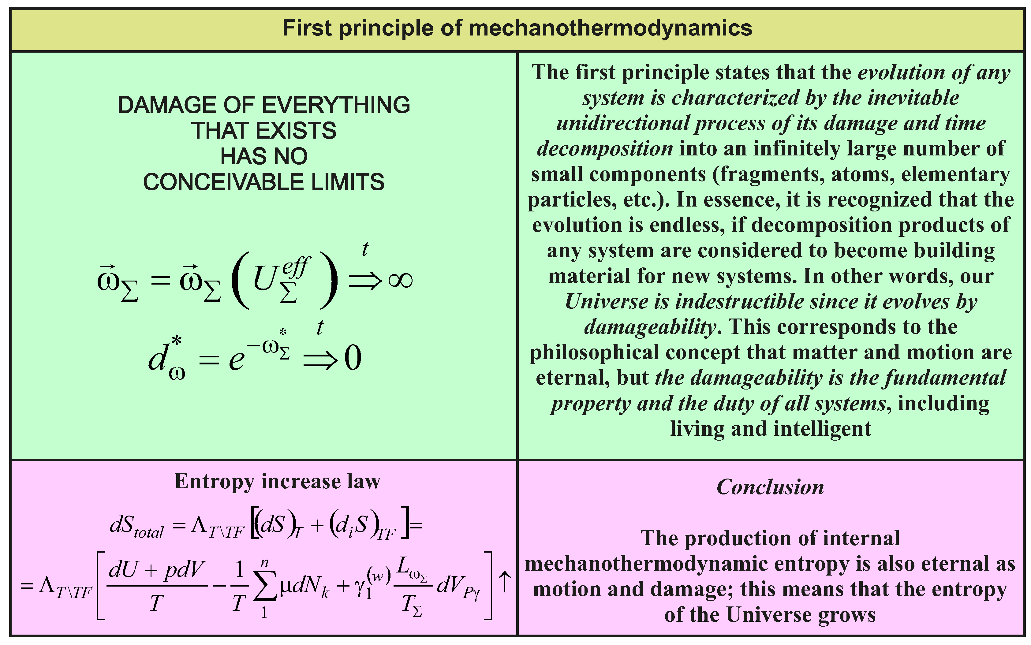
69], the fundamentals of Mechanothermodynamics are given and two of its principles are formulated: (1)
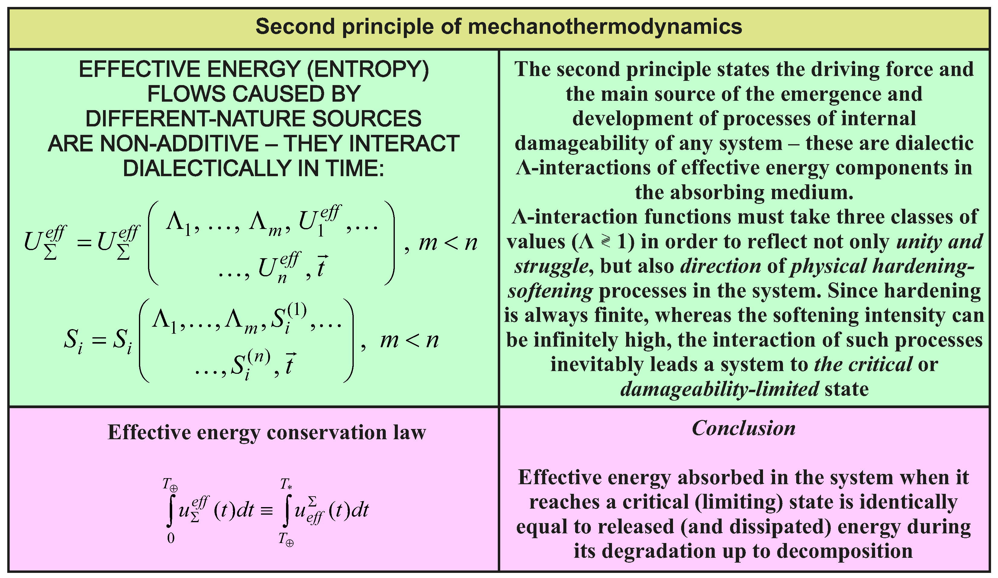
damage of all things has no conceivable boundaries; (2)
effective energy fluxes (entropy) that are caused by loads of different nature during irreversible changes in the MTD system have no additivity—they interact dialectically. In [
1], the analysis is made according to the main principles of Tribo-Fatigue [
2,
3,
4] and Thermodynamics [
5] and is based on the concept of
entropy. In this paper, the similar analysis is made on the basis of the energy representations of mechanics, tribo-fatigue, and thermodynamics. This has made it possible to reveal and investigate new regularities of the behavior and evolution of the mechanothermodynamical system.
2. Thermomechanical Statement
Consider the statement of thermomechanical problem [
5,
6,
7,
8] needed for further development of models of energy and entropy states of mechanothermodynamical systems.
Energy and entropy descriptions of continuum state of elementary volume
dV are of the following form [
6,
7]:
where σ
ij are stresses;
is density;
fi are volumetric forces;
are velocities.
The
law of conservation of mechanical energy for the continuum of the volume
V, with regard to the repeated index summation rule is obtained by multiplying scalar Equation (1) by the velocity vector
:
The right hand-side of Equation (2) is the
change in the kinetic energy K of the continuum of volume
V:
The equation for mechnical energy of continuum [
6] is derived basing on the known transformations with regard to
Gauss—Ostrogradsky’s theorem:
or:
where ε
ij is the strain rate; Π is the continuum surface; the
l are the direction cosines at the continuum surface; δ
U/
dt is the power of internal forces; δ
A/
dt is the power of internal surfaces and volumetric forces.
The symbol δ in expression (4) is used to underline that the increment in the general case cannot be an accurate differential.
In
the thermomechanical statement the rate of change in internal energy U [
6] is usually given by the integral:
where
is the specific internal energy (internal energy density) of the elementary volume of the mass Δ
m.
The
rate of heat transfer to the continuum is expressed as follows:
where
ci is the characteristic of the heat flux per unit area of continuum surface per unit time due to heat conduction;
z is the constant of heat radiation per unit mass per unit time.
The
law of change in the energy of thermomechanical continuum then assumes the form:
In (7), the transformation of surface integrals into volume integrals allows the
local form of the energy equation to be obtained:
If the scalar product of Equation (1) and the velocity vector
is subtracted from Equation (8), then the following form of the local energy equation is obtained:
where
is the heat flux per unit mass.
According to expression (9), the rate of change in the internal energy is equal to the sum of the stress power and the heat flux to the continuum.
As applied to the
thermodynamic system, two characteristic functions of its state are defined: absolute temperature
T and entropy
S that can be interpreted as the characteristic of ordering (or chaotic state) of the thermodynamic system. Usually it is assumed that the
entropy possesses the property of additivity, i.e.,:
In
continuum mechanics [
6,
7], the
specific entropy per unit mass is considered:
The
specific entropy increment ds can be due to the interaction with the environment (the increment
ds(e)) or inside the system itself (the increment
ds(i)) [
6,
7]:
The increment ds(i) is equal to zero in reversible processes and is greater than zero in irreversible processes.
If the heat flux per unit mass is expressed through
, then for reversible processes the increment will be:
According to the second law of thermodynamics, the rate of change in the total entropy
S of the continuum of the volume
V cannot be smaller than the sum of the heat flux through the volume boundary and the entropy produced inside the volume by external sources (
Clausius–Duhem’s inequality) [
6,
7]:
where
e is the power of local external entropy sources per unit mass. The equality in Formula (14) is valid for reversible processes and the inequality—for irreversible processes.
Transforming the surface integral into the volume integral in expression (14) can yield the relation for the
rate of the internal entropy production per unit mass:
In continuum mechanics, it is assumed that the stress tensor can be decomposed into two parts: the
conservative part for reversible processes (elastic deformation, liquid pressure) and the
dissipative part for irreversible processes (plastic deformation, liquid viscous stresses):
The expression for the
rate of change in energy (9) can then be presented in the following form:
If it is assumed that relation (13) is valid for irreversible processes, then the
rate of the total entropy production is:
or:
Expression (18) for the rate of a total change of local entropy in the elementary volume of the continuum can be very convenient in practice.
In view of assumption (10) on the entropy additivity the sum in (18) can be supplemented by other terms considering the internal entropy production in the liquid (gas) volume due to different mechanisms. Similarly, for the continuum volume
dV, for example, internal chemical processes can be considered [
5]:
If
dV is considered not as a finite volume but as an
elementary volume of continuum, then changes in its specific energy and entropy based on Equation (17), Equations (19) and (20) can be written in the following differential form:
where
nk is the number of mols per unit mass.
For the
continuum of the volume V, expressions (21) and (22) on the basis of relations (5) and (11) will assume the form:
The introduction of the chemical entropy component (the last terms in (21)–(23)) allowed one not only to obtain a more complete picture of the continuum state, but also to describe self-organization processes that result in initiating stable structures when the heat flux to the continuum is increased.
The above-presented known models of energy and entropy states of continuum (17)–(24), being rather general, do not nevertheless permit one to satisfactorily describe some processes occurring in such a continuum as a deformable solid. Convenient representation of the additivity of energy and entropy components (11) used, for example, for modeling elastic deformation is not suitable for the description of non-linear processes. The available models do not also allow for the entropy growth due to damageability of solids as a specific characteristic of changes in the structural organization. According to the tribo-fatigue concepts [
1,
2,
3,
4,
67,
68,
69], the damageability is interpreted as any irreversible change in structure, continuity, shape, etc. of a deformable solid that leads to its limiting state (separation into pieces under mechanical fatigue, occurrence of the pitting of critical density or sizes under contact fatigue, limiting wear under sliding fatigue). Although, for example, the elasticity limit is implicitly taken into account during plasticity modeling, the damageability, for example, during mechanical or contact fatigue occurs in the conditions of linear elastic deformation and requires a particular approach for its description with regard to limiting fatigue characteristics of material. The above drawbacks are overcome in the approach below.
3. Main Principles
According to [
2,
4,
67],
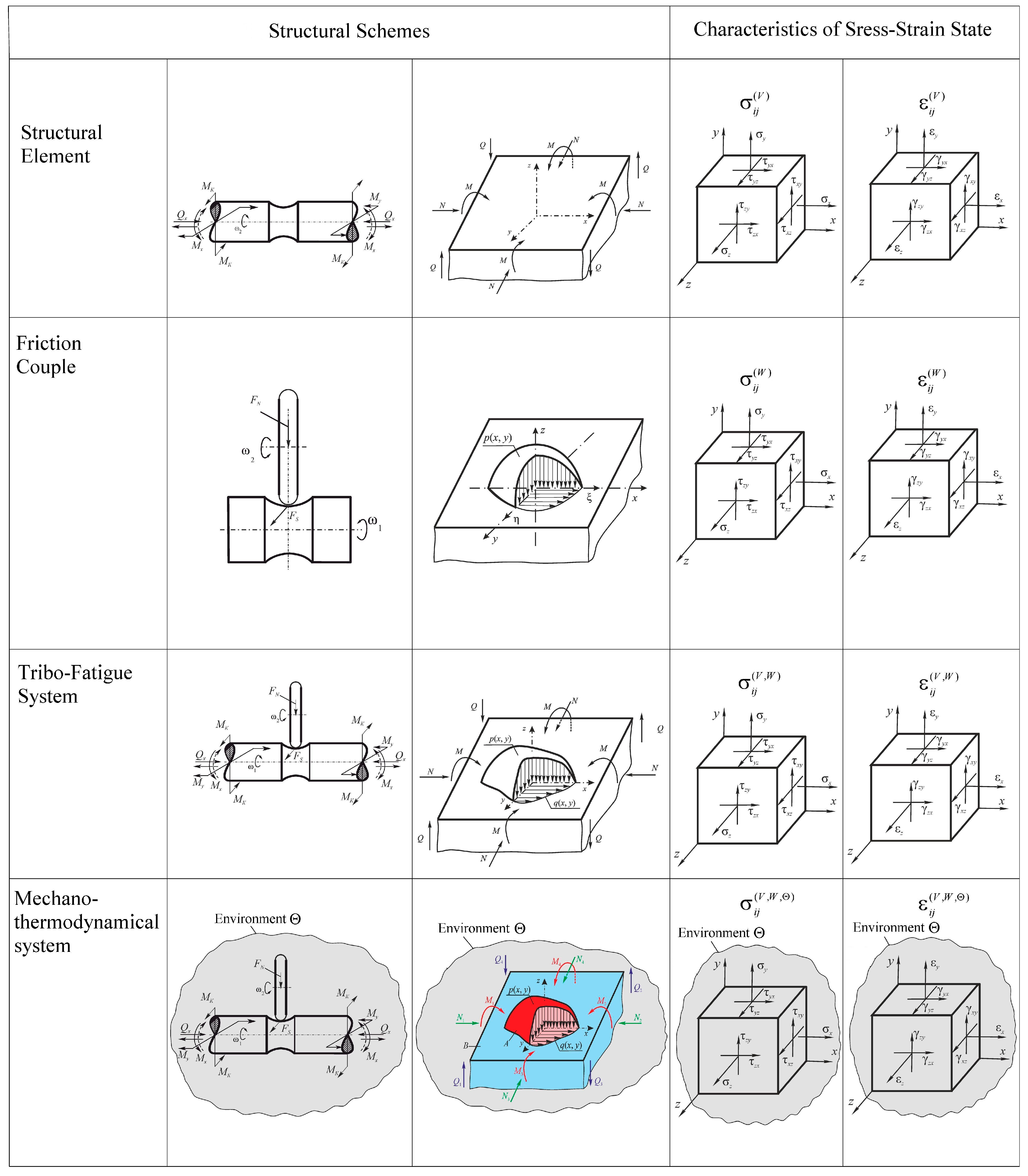
the mechanothermodynamical (MTD) system in the general case represents the thermodynamic continuum with solids distributed (scattered) within it, interacting with each other and with the continuum. Consider its fragment of limited size
shown in
Figure 1.
The continuum has a temperature θ and a chemical composition
Ch. Here are two interacting solid elements (A and B) that can move relatively to each other at the contact zone
S(
x,
y,
z). Arbitrary mechanical loads applied to one of them (for example, to element A) in
x,
y,
z coordinate system are transformed into the internal transverse forces
Qx,
Qy,
Qz, longitudinal forces
Nx,
Ny,
Nz and also into the bending moments
Mx,
My,
Mz. Element B is pressed to element A by the loads that are transformed into the distributed normal pressure
p(
x,
y) and the tangential tractions
q(
x,
y). The origin of the coordinates is placed at the point of original contact O of the two elements (prior to deformation). It is easy to see that the elements A and B together form the Tribo-Fatigue system [
4] which could be reduced to the friction pair [
2]
in the absence of internal forces (
,
,
,
i =
x,
y,
z). Thus, the Tribo-Fatigue system
is the friction pair in which at least one of the elements perceives non-contact loads and, consequently,
undergoes volumetric deformation. This representation of the MTD system has an advantage that the analysis of the states of a solid and the components of a system can adopt the appropriate solutions known in mechanics of deformable solid, in contact mechanics, in mechanics of tribo-fatigue systems (tribo-fatigue) and in tribology.
Our main task is to describe the energy state of the MTD system under the action of mechanical and thermodynamic loads with regard to the environmental influence.
The energy state of any system is very interesting in itself. However, as applied to the MTD system it is very important to study
its damage and, as a result, to study
the conditions of reaching the limiting state (fatigue fracture, wear etc.). Of special interest is the analysis of translimiting or supercritical conditions [
2].
The main ideas, which are the fundamentals of the given theory, can be formulated with regard to [
2,
3,
4] as follows:
I. Due to the fact that the elements of the MTD system are subject to the loads of different nature—mechanical, thermal and electrochemical, the traditional analysis of their damage and limiting state under the action only of mechanical stresses or strains [
70,
71,
72,
73,
74,
75,
76,
77,
78] etc. can be the basis for research. However it appears insufficient and, as a result, is ineffective. This means that there is a need to analyze MTD system states using more general energy concepts.
II. Considering that the damage of MTD system solids is determined by mechanical, thermodynamic [
79,
80,
81,
82,
83] etc. and electrochemical loads, it is needed to introduce
the generalized representation of its complex damage that is caused by these loads acting at a time. Call such damage
any irreversible changes in shape, size, volume, mass, composition, structure, continuity and, as a result, physical and mechanical properties of the system elements. This means the corresponding
changes in the functions of the system as the integrity.
III. The onset and development of complex damage is mainly determined by means of four particular phenomena: mechanical fatigue, friction, wear, thermodynamic and electrochemical processes. These phenomena are called particular in the sense that each of them can be realized as independent and separate. This leads to the corresponding energy state and damage in terms of particular (separate) criteria.
IV. In the general case, all these particular phenomena and processes in the MTD system appear simultaneously and within one area. The states of such a system are then caused not by one of any mentioned phenomena but by their joint (collective) development and, consequently, by their interaction.
V. If the physical state of the MTD system is described by means of all input energy , then its damage condition is determined only by the effective (dangerous) part that is spent for generation, motion, and interaction of irreversible damages.
VI. The effective energy
at the volume strain of solids can be represented by the function of three energy components:
thermal ,
force , and
frictional :
where
FΛ takes into account the irreversible kinetic interaction of particular damage phenomena. The components
of the effective energy
have no property of additivity.
VII. The processes of electrochemical (in particular, corrosion) damage of solids can be taken into consideration by introducing the parameter 0 ≤
Dch ≤ 1 and can be studied, for example, as
electrochemical damage under the influence of temperature (
DT(ch)),
stress (
Dσ(ch)), and
friction corrosion (
Dτ(ch)). So function (25) takes the form:
VIII. The generalized criteria of the limiting (critical) state is represented by the condition when the effective energy reaches its limiting value—critical quantity u0 in some area of limited size—in the dangerous volume of the MTD system.
IX. The energy u0 is considered to be a fundamental constant for a given material. It shouldn’t depend on testing conditions, input energy types, damage mechanisms.
X. Dangerous volume is the 3D area of the deformable solid ( is its working volume) with the critical state of material at all its points, of which it consists.
XI. In the general case, the limiting (critical) state of the MDT system is reached not due to a simple growth of effective energy components and, hence, due to the accumulation of irreversible damages that are caused by separate actions (loads of different nature), but as a result of
their dialectical interaction, whose direction is characterized by the development of spontaneous phenomena of hardening-softening of materials in the given operating or testing conditions. In such a way, taking into consideration function (26),
the hypothesis of the limiting (critical) state of the MTD system can be represented in the following general form:
where
mk,
k = 1, 2, …, are some
characteristic properties (hardening-softening) of contacting materials,
⋛ 1 are
the functions (parameters) of dialectic interactions of effective energies (irreversible damages) that are caused by loads of different nature. This means that at Λ
k > 1, the damage increase is realized, at Λ
l < 1—its decrease, and at Λ
n = 1—its stable development.
XII. Taking into consideration Item III, from the physical viewpoint, hypothesis (27) should be multi-criterion, i.e., it should describe not only the states of the system as the integrity but its separate elements in terms of different criteria of performance loss (wear, fatigue damage, pitting, corrosion damage, thermal damage, etc.). In particular cases, it is possible to reach the corresponding limiting (critical) states in terms of one or two, three or several criteria at a time.
XIII. Reaching the limiting state:
means
the full loss of the integrity of the MTD system, i.e.,
of all its functions. At the same time
damageability of its elements:
reach the
critical value:
XIV. If
t =
t0 is the time of origination of the system and
is the time of reaching the limiting state, then
the failure time of its functions corresponds to the
relative lifetime (longevity) . But
the system lifetime as
the material object is longer than its lifetime as the functional integrity (
) since at the time moment
the process of
degradation—disintegration is realized by forming a great number of remains, pieces, fragments, etc. This process develops under the influence of not only possible mechanical loads but mainly of the environment—up to
the system death as the material object at the time moment
t =
. The system death means
its complete disintegration into an infinitely large number of ultimately small particles (for example, atoms).
The translimiting existence of the system as a gradually disintegrating material object can then be described by the following conditions:
where
is the average size of disintegrating particles and the natural relation
should exist between
and
. Then
the condition for the system death is:
XV. The particles of the “old system” disintegration are not destructed but are spent for the formation and growth of a number of “new systems”. This is the essence of the MTD system evolution hysteresis.
Finally it should be noted that not irreversible but effective energy causing damages production is considered in the present work. Determination of parameters denoting effective (damaging) part of energies of different nature (due to stresses, friction, temperature) is explained in
Section 4 “Energy Theory of Damage and Limiting States”.
Our idea is that failure depends on fundamental physical property of the material—critical energy u0 which is independent of the conditions of deformation, shapes and sizes of objects. Limiting energy u0 is considered as the initial activation energy of the disintegration process (critical energy) which approximately corresponds both to the sublimation heat for metals and crystals with ionic bonds and to the activation energy of thermal destruction for polymers. It is independent of conditions and ways of reaching the limiting state. Longevity of a gear or a shaft in the given conditions of operation would be different but determined by fundamental parameter u0.
On the other hand effective energy is of course dependent on all these conditions and external loads and corresponding stress-strain state. Limiting state occurs when effective energy reaches u0. In cases of different sizes, shapes, number of cycles and stress concentrators effective energy is different. Therefore it may need different conditions and time for effective energy to reach fundamental material constant u0.
In our case entropy is defined as the ratio between the effective energy and critical energy
u0 (see
Section 5 “Mechanothermodynamical states”). Therefore the proposed formulation of entropy simultaneously contains acting and critical energy. The limiting state occurs when this ratio is equal to 1. Latter studies could show effectiveness of this in certain cases.
4. Energy Theory of Damage and Limiting States
Let us specify function (25). To determine the effective energy, consider
the work of internal forces in the elementary volume dV of tribo-fatigue systems (in
Figure 1). In the general case, the differential of the work of the internal forces and the temperature
dT∑ can be written with regard to the rule of disclosing the biscalar product of
the stress and strain tensors σ and ε:
here
k is the Boltzmann constant.
We proceed from the idea that in the general case, according to [
2,
4], the main role in forming wear-fatigue damage is played by the normal and shear stresses that cause the processes of
shear (due to friction) and tear (due to tension-compression).In this case, it is reasonable to divide the tensor σ into two parts: σ
τ is
the tensor of friction-shear stresses, or, briefly,
the shear tensor and σ
n is the tensor of normal stresses
(tension-compression), or, briefly,
the tear tensor. So in (28), the tear part σ
n and shear part σ
τ of the tensor σ will be set as:
According to items III and IV, the tensors σ and ε should be represented as follows:
Here the stress and strain tensors with the superscript
V are caused by the action of volume loads (the general cases of 3D bending, torsion, tension-compression) and those with the superscript
W—by the contact interaction of the system elements. Expression (35) with regard to (36) can be given as follows:
In the case of the linear relationship between the stresses and strains, expression (36) will assume the form:
and (37) will be as follows:
From (40) it is seen that the tear part σn of the tensor σ is the sum of the tear parts of the tensors at the volume strain and the surface load (friction) , whereas the shear part στ is the sum of the shear parts and . This means the vital difference of the generalized approach to the construction of the criterion for the limiting state of the MTD system.
From total energy (40), its effective part is separated according to Items V and VIII with regard to [
2,
3]. To do this, introduce the coefficients of appropriate dimensions
An(
V),
Aτ(
V) and
AT(
V) that determine the fraction of the absorbed energy:
or:
where Λ
M\T(
V) and Λ
τ\n(
V) are the functions of interaction between energies of different nature. The subscript τ\
n means that the function Λ describes the interaction between the shear (τ) and tear (σ) components of the effective energy, and the subscript
М\
T means that the function Λ describes the interaction between the mechanical (
M) and thermal (
T) parts of the effective energy. That fact that the coefficients
A can be, generally speaking, different for different points of the volume
V, enables one to take into account the inhomogeneity of environment.
Taking into consideration (42), criteria (27) can be specified with no regard to the environmental influence:
In the case of the linear relationship between the stresses and strains, expressions (41) and (42) will be as follows:
or:
With regard to expression (36), criterion (43) can be represented as follows:
When the time effects should be taken into consideration, criterion (46) will assume the form:
Thus, expression (45) is the concretization of function (25) and formula (46) is the concretization of criterion (27) for that case when the environmental influence is not taken into account.
Criterion (27) in the form of (46) and (47) says: when the sum of interacting effective energy components caused by the action of force, frictional, and thermal (thermodynamic) loads reach the critical (limiting) quantity u0, the limiting (or critical) state of the MTD system (of both separate elements of the system and the system as the integrity) is realized. Physically, this state is determined by many and different damages.
The fundamental character of the parameter
u0 has been mentioned above. According to [
82,
83,
84,
85,
86,
87,
88,
89,
90,
91,
92,
93,
94,
95], the parameter
u0 will be interpreted as
the initial activation energy of the disintegration process. It is shown that the quantity
u0 approximately
corresponds both to the sublimation heat for metals and crystals with ionic bonds and
to the activation energy of thermal destruction for polymers:
On the other hand, the quantity
u0 is determined as
the activation energy for mechanical fracture: In such a way, the energy
U0 can be considered to be
the material constant:
Taking into consideration the physical-mechanical and thermodynamic representations of the processes of damage and fracture [
84,
85,
87], write down (48) in the following form:
where
sk is the reduction coefficient, σ
th is the theoretical strength,
E is the elasticity modulus,
Ca is the atom heat capacity, α
V is the thermal expansion of the volume,
k is the Boltzmann constant,
TS is the melting point, θ
D is the Debye temperature,
h is the Planck constant. According to (49), it can be taken approximately [
84]:
where
≈ 0.6 is the limiting strain of the interatomic bond. Calculations according to (50) are not difficult. Methods of experimental determination of the quantity
u0 have also been developed [
85].
From equality (49) it follows that
u0 is the activation energy of a given material, which is by the order of magnitude equal to 1–10 eV per one particle or molecule (~10
2–10
3 kJ/mol), i.e.,
the value that is close to the energy of interatomic bond rupture in the solid [
88]. Its level doesn’t depend on how the rupture is —mechanically, thermally or by their simultaneous action. In [
85], it is possible to find the tables containing the
u0 values for different materials.
From (49) it is possible to find the
thermomechanical constant of the material [
2]:
The constant θσ characterizes the strength loss per 1 К.
Criterion (46) is written in the absolute values of physical parameters—the values of the effective and critical energy components. This criterion can be easily made dimensionless by diving it by the quantity
. Then it can be represented
in terms of irreversible (effective) damage:
It is clear that
the local (at the point) energy measure of damage is within the range:
or in detailed form:
According to (54), it is also possible to determine
particular energy measures of damage:
due to the effective energies of different nature that are determined by the force (the subscript
n), frictional (the subscript τ), and thermodynamic (the subscript
T) loads, respectively. Now criterion (52) can be written in dimensionless form:
According to (58), the limiting state of the MTD system is reached when the sum of interacting damages (0 < ψ < 1) at mechanical and thermodynamic loads is equal to 1. Criterion (46) in form (58) is convenient because all damage measures are dimensionless and are within the same range 0 ≤ ψ ≤ 1.
Since numerous and infinite actions, as well as the interaction effects of physical damages of many types (dislocations, vacancies, non-elastic deformations, etc.) cannot be described and predicted exactly, when analyzing the MTD system, one introduces the concept of
the interaction of dangerous volumes [
2] that contain a real complex of damages (defects generated by the action of the corresponding fields of stresses (strains)). According
to the statistical model of the deformable solid with the dangerous volume [
88], such a volume should depend on the geometric parameters of the solid responsible for its working volume
V0, on the distribution function parameters
p(σ
−1) and
p(σ) of the durability limit σ
−1 and the effective stresses σ considering both the effective stress probabilities
P and
γ0 and gradients
Gσ:
Here describes how the limiting durability is influenced by the body shape and the scheme of body loading during fatigue tests.
Thus, the dangerous volume can serve as the equivalent of the complex of damages, as its value is proportional, in particular to the level of effective stresses and, hence, to the number (concentration) of defects (damages).
The boundary between the volumes of dangerous and safe, as it follows from expression (59), is generally blurred and probabilistic in nature. As the damage probability
P of the solid increases, the dangerous volume
is growing. At a given value of
P the volume can vary depending on the confidence probability
. It means that at
P = const:
if
. Here
form the permissible range. If it is accepted that
= const, then the dangerous volume will have a single value associated with the damage probability
P.
Scattered damage within the dangerous volume is characteristic not only for the so-called smooth bodies but also for the elements with the structural
stress concentrators [
88].
Thus, if in the uniaxial stress state, the stress distribution
(
x,
y,
z) in
x,
y,
z coordinates is known, then
the dangerous volume should be calculated by the formula:
where
being the lower boundary of the range of the durability limit
statistical distribution is such that if
, then
P = 0.
From expression (61) it follows that
the generalized condition for fatigue fracture is of the form:
with some probability
P under the confidence probability
.
If:
then the fatigue damage cannot occur physically (because in this case,
); hence, (63) is
the generalized condition of non-fracture.The methods for calculation of dangerous volumes
for friction pairs and tribo-fatigue systems are developed similar to (59):
and outlined in [
4,
90,
91,
92]. Here
is the limiting stress based on the assigned criterion of damage and fracture.
Further, the following dimensionless characteristics of damage can be introduced:
integral energy damage within the dangerous volume:
and
the average energy damage (at each point of the dangerous volume):
The accumulation of energy damage in time within the dangerous volume is described by the formulas:
Having used (63)–(68), the MTD system damage can be described and analyzed using the most general representations—the energy concepts with regard to the influence of numerous and different factors taken into account by (59), including the scale effect, i.e., the changes in the size and shape (mass) of system elements.
According to [
2,
95], the function Λ
k\l\n for damage interactions in the MTD system is determined by the parameters ρ of the effective energy ratio (Λ
k\l\n):
The quantities Λ calculated by (69) describe the influence of the load parameter ratio on the character and direction of interaction of irreversible damages [
2,
3,
4].
If Λ > 1, then
the system is self-softening because at the balance of hardening-softening phenomena, softening processes are dominant.
If Λ < 1,
the system is self-hardening, because at the balance of hardening-softening phenomena, hardening processes are dominant. At Λ = 1,
the system is stable—the spontaneous hardening-softening phenomena are at balance in it. The general analysis of damage interactions in the MTD systems will be given on account of its fundamental importance in a separate paper.
After criterion (27) has been basically formalized, the action of electrochemical loads (damages) should be taken into consideration according to Item VII. It should be said at once that it is difficult to do in the strict mechanothermodynamical statement: electrochemical reactions are very diverse and complex, when the environment interacts with a deformable solid body, and are insufficiently studied. That’s why, the approach proposed in [
2,
3] is adopted: the simplification is introduced, according to which the damage of solids in the environment is determined by corrosion-electrochemical processes. In addition,
the hypothesis is put forward, following to which the effective energy of corrosion-electrochemical damage is proportional to the square of the corrosion speed, i.e.,:
If according to Item VII, 0 ≤
Dch ≤ 1 is the parameter of corrosion-electrochemical damage of the body, then based on [
2,
4,
92], criterion (26) with regard to its shape will be as follows:
where:
Here is the corrosion speed in this environment, , , is the corrosion speed in the same environment under thermal, force, and friction actions, respectively; be are the coefficients responsible for corrosive erosion processes; mV(•) are the parameters responsible for the electrochemical activity of materials at force (the subscript σ), friction (the subscript τ), and thermodynamic (the subscript T) loads, wherein mV(•) = 2/Ach and the parameter Ach ⋛ 1.
In [
95], other methods for assessment of the parameter
Dch can be found. As seen, Equation (72) is the specification of criterion (27).
According to this criterion, the limiting state of the MTD system is reached when the sum of dialectically interacting irreversible damages at force, friction, and thermodynamic loads (including electrochemical damage when acted upon by stress, friction, temperature) becomes equal to unity.
Further, consider the particular case when in (46) it is assumed that Aσ(V) = Aσ = const, Aτ(V) = Aτ = const, AT(V) = AT = const, (V) = = const, (V) = = const.
Firstly, the stress state is caused by volume deformation, for which all components of the stress tensor, except for one component σ (one-dimensional tension-compression, pure bending), can be neglected. Secondly, the stress state is caused by surface friction, for which all components of the stress tensor, except for one component τ
w, can be neglected. Then (40) assumes the following form:
or in accordance with (72):
where
,
,
.
Thus, Equation (77) is the simplest form of the energy criterion of the limiting state that is nevertheless of great practical importance [
2].
If there is no electrochemical influence of the environment (
= 0), then:
Equation (78) is the simplest form of the energy criterion of the limiting state, which, nevertheless, is of great practical importance [
2,
92,
95]. It serves particularly for the development of methods of assessing the parameters
. In fact, at
, the boundary conditions are the following:
where σ
d, τ
d are the force and friction limiting stresses as
T → 0. These are called the limits of (mechanical) destruction,
Td is the destruction temperature (when σ = 0, τ
w = 0) or the thermal destruction limit.
The effective (“dangerous”) part of total energy of strain can also be determined from the following physical considerations. It shall be assumed that the
strain energy flux U generated in the material sample during its cyclic strain (
) in the homogeneous (linear) stress state is to a certain extent
similar to the light flux. In fact, it is continuously excited when the loading cycle is repeated with the speed
. This enables one to consider it as a wave (with the length λ). Some part of the energy
u generated in such a way can be absorbed by material atoms and structural formations, followed by damage of material. Denote the absorbed part of the energy by
ueff. Then the generated energy
u is equal to:
where
ucons is the non-absorbed part (it is called the conservative part) of the generated energy
u.
If the analogy of light and energy strain is justified, then the strain absorption law may be similar to
Bouguer’s light absorption law. Consequently, the equation relating the energy
ucons passed through the material strain volume
V and the generated energy
u is of the form:
or, in accordance with
Lambert, in differential form:
Here as in Bourguer—Lambert’s equation, the coefficient χε independent of u is the energy absorption parameter.
Taking into account (81) into (80),
the strain energy absorption law is obtained:
and hence if
u = 0 or
V = 0 then
ueff = 0. If
V → ∞ it appears that according to (81)
ucons =
u, i.e., all input energy is dissipated within such a volume.
From the physical point of view, the strain energy absorption process is caused by many phenomena:transition of electrons in absorbing atoms from lower to higher energy levels (quantum theory);
generation and development of dislocation structures (dislocation theory);
emergence of II and III order residual strains (stresses) (elasticity theory);
formation and development of any imperfections (defects) of material composition and structure—point, planar and spatial (physical materials science);
hardening-softening phenomena (including strain aging) developing in time (fatigue theory);
changes in (internal) Tribo-Fatigue entropy (wear-fatigue damage mechanics [
2]).
It should be noted that approach (83) can also be extended to the case of friction, since any indenter drives a strain wave upstream in the thin surface layer of the solid to which indenter is pressed to. Energy absorption parameter in this case will be χγ where the subscript γ denotes the shear strain. Similarly, heat absorption in the deformable solid body can also be considered. Finally, the problem of strain energy absorption in the non-uniform (including complex) stress state can be easily solved by putting the dangerous volume into (81)–(83).
It should be noted that although criterion (78) is special, it is fundamental and general in nature. Its general nature is caused by the fact that in this case, all four particular phenomena responsible for the MTD system state (in the statement simplified in terms of the stress-strain state) are taken into account (in accordance with Item III). Its fundamental nature is that here, as in complete solution (46), Λn\τ takes into account the interaction of effective mechanical energy components caused by friction τw and normal σ stresses, whereas ΛM\T takes into account the interaction of the thermal and mechanical components of the effective energy. The effective energy thermal component is determined by the variations of the total temperature T∑ = T2 − T1 in the bodies contact zone caused by all heat sources, including the heat released during mechanical (spatial and surface) strain, structural changes, etc.
5. Mechanothermodynamical States
Within the framework of mechanothermodynamics a special approach is being developed to assess the entropy in terms of a generalized energy state. Following this approach and formula (77), out of the
total energy (specific) due to some particular loads (force, temperature, etc.),
its effective part directly spent for the damage production is defined by the experimentally found coefficients
Al in formulas (41), (42), (77) [
2,
3,
4,
5,
6,
7,
8,
9,
10,
11,
12,
13,
14,
15,
16,
17,
18,
19,
20,
21,
22,
23,
24,
25,
26,
27,
28,
29,
30,
31,
32,
33,
34,
35,
36,
37,
38,
39,
40,
41,
42,
43,
44,
45,
46,
47,
48,
49,
50,
51,
52,
53,
54,
55,
56,
57,
58,
59,
60,
61,
62,
63,
64,
65,
66,
67,
68]:
where the
ul are the specific internal energies at tear (
un), shear (
uτ), thermal action (
uT).
The total specific energy of an elementary volume and a rate of its change are then given as:
Moreover, the Λ-functions are used to take into consideration a complex (nonadditive) character of interactions between effective energies of different nature expressed by formula (42). This allows the
total effective energy of the system to be assessed:
where the Λ
α are the possible combinations of interaction of effective energies (irreversible damages).
The
specific feature of Λ-functions is such that:
and hence:
Thus, using coefficients
Al and Λ-functions it is possible to assess
energy interaction due to different-nature loads. Such interaction can cause both a sharp growth and a substantial decrease of effective energy, resulting in damages and limiting states, as compared to the one calculated by the ordinary additivity model of type (17):
The
total effective energy of volume
V and its accumulation in time with regard to formula (87) are of the form:
and:
The principal moment of the mechanothermodynamical model is the
account of the limiting state (limits of plasticity, strength, fatigue, etc.) according to Item XIII:
where
u0 is the limiting density of the internal energy interpreted as the initial activation energy of the disintegration process.
A relationship between the current state (mechanical, thermomechanical, energy) of an elementary volume of a solid (medium) and its limiting state enables one to construct the
parameter of local energy damageability: dimensionless:
or dimensional:
Local energy damageability (94) or (95) is most general out of the damageability parameters constructed in terms of different mechanical (thermomechanical) states φ [
2,
3,
4,
5,
6,
7,
8,
9,
10,
11,
12,
13,
14,
15,
16,
17,
18,
19,
20,
21,
22,
23,
24,
25,
26,
27,
28,
29,
30,
31,
32,
33,
34,
35,
36,
37,
38,
39,
40,
41,
42,
43,
44,
45,
46,
47,
48,
49,
50,
51,
52,
53,
54,
55,
56,
57,
58,
59,
60,
61,
62,
63,
64,
65,
66,
67,
68]:
where φ = σ, ε,
u; the σ are the stresses; the ε are the strains;
u is the density of internal energy; the
are the limiting values of the state φ
;
eqv is the equivalent mechanical state; the
ij are the components of the tensor φ; the
i are the main components of the tensor φ;
S and
and the sphere and deviator parts of the tensor φ;
n and τ are the normal and tangential components of the tensor φ; int is the intensity φ;
u is the specific potential strain energy (internal energy density); the indices at
u mean:
and
are the specific potential strain energy at tension-compression and shear;
is the effective specific potential strain energy.
Integral damageability measures can be built on the basis of local measures (96) with the use of the model of a deformable solid with a dangerous volume (64)–(68) [
89].
By the
dangerous volume is understood the spatial region of a loaded solid, at each point of which the value of local damageability is smaller than the limiting one [
2,
3,
4,
5,
6,
7,
8,
9,
10,
11,
12,
13,
14,
15,
16,
17,
18,
19,
20,
21,
22,
23,
24,
25,
26,
27,
28,
29,
30,
31,
32,
33,
34,
35,
36,
37,
38,
39,
40,
41,
42,
43,
44,
45,
46,
47,
48,
49,
50,
51,
52,
53,
54,
55,
56,
57,
58,
59,
60,
61,
62,
63,
64,
65,
66,
67,
68]:
or:
Dangeous volumes are calculated by the following general formula:
The
integral condition of damageability of a solid or a system can be written in the form:
where
V0 is the working volume of the solid.
To analyze at a time dangerous volumes local damageability distributed within them, the
function of damageability of unit volume is introduced:
The
function of damageability of the entire volume V will then be as:
The simplest functions of
damageability accumulation in time for unit volume and the enrire volume will be of the following form, respectively:
The
indices of volume-mean damageability:
and
its accumulation in time can be used:
The analysis of formulas (94), (100), (102) comes to the conclusion that conceptually, they are related to the concept of entropy as a difference (or relations) between two states (configurations) of a system, the degree of its organization (chaotic state). As applied to damageability, such states are current and limiting.
Now using local energy damageability (94), construct
specific (per unit mass)
tribo-fatigue entropy (up to a constant):
or:
where
is the dimensional parameter (J·mol
−1·K
−1).
On the basis of the expressions for entropy (18), аs well as of formulas (85), (86) the
local entropy and the
rate of its change within an elementary volume will be:
and:
From formulas (108) and (109), it is seen that unlike the thermomechanical model, the state indices of the mechanothermodynamical system u and s are not equivalent. This is due to the fact that the calculation of the specific tribo-fatigue entropy by formula (106) is supplemented by the limiting state in the form of the limiting density of the internal energy u0.
The tribo-fatigue entropy
is calculated not within the entire volume
V, but only within its damageable part, i.e., within the energy effective dangerous volume
:
On the basis of formulas (11), (106) and (110), the
tribo-fatigue entropy of volume V will be:
where:
or:
and
its accumulation will be:
where:
or:
The principal feature of tribo-fatigue total and specific entropies should be emphasized. They allow the difference between two states to be assesses not only quantitatively (as thermomechanical entropy), but also qualitatively, as the value of the limiting density of the internal energy u0 is explicitly introduced into the calculation of the specific entropy . Thus, and allow one to answer the question how much the current state of a solid or a system is dangerous in comparison with limiting states.
The
total entropy and the
rate of its change for a solid of a system with regard to (111) and (113) assume the form:
and:
Based on formulas (106)–(116), the
function of accumulation of total entropy in time can be built:
In this respect, bearing in mind the limiting states of a solid or a system, models (115)–(117) permit one to answer the question whether the current state is the point of a qualitative jump in the system, i.e., whether the current state is close to the limiting one. A similar (dialectical as a matter of fact) qualitative transition differs, for example, from the bifurcation point having the uncertainty in a further development of events and the possibility to predict the system behavior after a transition on the basis of the analysis of and . Particular limiting states (limit of strength, mechanical or contact fatigue, etc.) enable one to predict the situation after transition the given point: principal changes in the system properties and behavior or the formation of a new system based on the previous one.
As an example, there can be non-linear deformation or generation of microcracks in the solid (or the system) that cause the changes in its strength and fatigue properties, and, hence, to its response to loads. In turn, formed macrocracks lead to local continuum violation—formation of new free surfaces (possibly, of new solids—destruction products), i.e., a new system.
It should be noted that models (115)–(117) were built using a traditional concept of entropy additivity (10) although with regard to substational improvements. These models also contain reversible processes described by the entropy components sl not yielding primary damages and, hence, the limiting states—the points of a qualitative change of the system.
It is therefore more advisable for a qualitative and quantitative analysis of evolution of systems (whose states are traditionally defined as bifurcation branches) that the entropy state should be determined using the mechanothermodynamical model of the solid using only tribo-fatigue entropy. In this case, formulas (111)–(113) for entropy and its accumulation will be of the form:
and:
To identify the points of qualitative change in the limiting states of solids (systems), the indices of relative integral entropy and its accumulation built on the basis of the concept of integral condition of damageability of a solid (99) can be used:
The indices , , , ωS, can grow infinitely, allowing not only the limiting states of type (93), but also different transmitting states to be described; in essence, they “provide” a quantitative description of the law of increase of entropy.
Now based on formulas (24), (115), (117) and (119) let us construct
generalized expresssions for entropy, a rate of its change аs well as
its accumulation in the mechanothermodynamical system consisting of a liquid (gas) medium of volume V and
a solid of volume Vψ:
Entropy state indices can be built similarly for a system composed of many media.
It should be noted that the interaction (contact) of two media in formulas (122)–(125), which can be complex in nature, is taken into account only implicitly in terms of medium state parameters (stresses, strains, temperature). It is obvious that this is only the first step to a comprehensive (generalized) solution of the problem stated.
The simplified writing of expression (123) for the entropy increment of the mechanothermodynamical system composed of finite volumes
dV and
dVψ given in [
68] can be re-written in the following form:
Expression (125) can also be represented in terms of specific quantities as:
or on the basis of (123) as:
In formulas (111)–(113) for calculation of the tribo-fatigue entropy
and its accumulation
, the specific entropy
is assumed to be integrated in terms only of the damageable part of the solid—the dangerous volume. However the influence of undamagable regions can also be allowed for by integrating
over the entire volume:
where:
or:
From expression (131), it is seen that < 0 is observed outside the dangerous volume (at ). This means that the specific tribo-fatigue entropy also appears to be negative (or less than unity for its alternative definition) outside the dangerous volume where the limiting state is not reached. Negative values of and can then be interpreted as the absence of damageability or in other words as the retention of structure and/or properties of the solid.
As follows from the above-stated, the assumption on the entropy additivity is wrong in the general case for a system composed of both a solid and a liquid (gas) where chemical reactions can occur. By analogy with Λ-functions, interaction functions of different-nature energy (179) it is necessary to introduce
interaction functions of different-nature entropy by adding them to expression (125) in effort to determine total effective entropy:
or:
where the subscripts
Q and
Ch denote the thermodynamic and chemical entropy components.
Formulas (132)–(133) are supplemented by the generalized interaction functions , , in mechanothermodynamical systems. This means that the hypothesis on the additivity of thermodynamic and tribo-fatigue entropy is not accepted. The appropriate Λ-functions of interactions should then be specified and introduced into Equations (132)–(133).


