1. Introduction
The use of thermally activated refrigerators has the potential to reduce CO2 and other damaging emissions. Because of their relatively high coefficients of performance, LiBr-H2O vapour absorption cycle refrigerators are seen as an important technology in this area. Furthermore, since the refrigerant is water, there is no danger that fugitive emissions can damage the ozone layer or contribute to global warming. However, a drawback to the wider use of LiBr-H2O absorption refrigerators has been their relatively high capital cost compared to electric vapour compression machines with similar cooling capacities. A significant contribution to the capital cost of small-scale, sub-kilowatt, absorption refrigerators is thought to be that of the solution recirculation pump. The present paper describes a novel absorption refrigeration cycle which avoids the use of a solution pump in the normal sense and which it is thought will suit the design of small capacity refrigerators for applications such as small capacity chilled drink cabinets and vaccine coolers.
Because of their low energy efficiency, the electrical power consumption of small-scale absorption refrigerator circulation pumps might in some cases be better used to drive a conventional electrically powered vapour compression refrigerator. Xu and Wang [
1] provide a very useful general discussion on various types of absorption cycle including combined cycles and a recent research report by Asdrubali et al. [
2] summarized the thermal and electrical performance of small scale LiBr-H
2O absorption cycle machines. By taking into account both heat and electrical input, overall Coefficient of Performance (COP) values were shown to be in the range 0.53–0.64 for machines with cooling capacities in the range 5.2 to 11.4 kW [
2]. This author believes that the problem of electrical inefficiency may be exacerbated for similar machines with cooling capacities of less than one kilowatt.
The idea of using thermal energy alone to circulate the working fluids through absorption cycle refrigerators is not new. The diffusion absorption refrigeration (DAR) cycle uses a bubble pump to circulate the solution, as described in the ASHRAE Handbook [
3]. A key to high efficiency DAR cycles lies in the design of the bubble pump. These have been the subject of investigation for many years. Recently, Gao at al. [
4] theoretically investigated the motion of bubbles within a vertical tube for which the vapour–liquid density ratio was over 270. They studied single and twin bubble formations along with coalescence tims of the latter in order to understand their influence of liquid entrainment; however, bubble formation (nucleation) was not considered in that study. Benhmidene et al. [
5] undertook an experimental investigation of bubble pump operation in a DAR system, finding that submersion ratio and generator heat input played important roles in the performance of the pump. Zohar and Jelinek et al. [
6] investigated the influence of the generator and bubble pump design on the performance of DAR systems. They showed that bubble pump performance, and therefore COP, can be improved by changing the construction of the bubble pump. Their results showed that an 86% increase in COP was possible by altering the design of the bubble pump lift tub, however, but the absolute COP value were never better than 0.34, which is low compared with values expected of typical LiBr-H
2O single-effect vapour absorption refrigerator (VAR) systems. An et al. [
7] described an interesting theoretical and experimental study on the lifting performance of bubble pump with a lift-tube of varying diameter. The rig design was described and experimental results were given. The efficiency results were a little confusing but otherwise the paper was most interesting. Various combinations of refrigerant, absorbent and inert gas have been tested for DAR systems. The normal working vapour pressures of the refrigerants tested so far in DAR systems have been in excess of atmospheric pressure, which aids the nucleate boiling process used by bubble pumps. However, COP values have tended to be significantly lower than that of a conventional single-effect LiBr-H
2O absorption cycle refrigerator.
The bubble pump has been suggested for use in LiBr-H
2O VAR systems. Saravanan and Maiya [
8] investigated the influence of thermodynamic and thermophysical properties on water-based working fluids for bubble pumps for VAR systems. This paper discusses the benefits of various aqueous–salt solutions (binary, tertiary and quaternary) with regard to variations in density and vapour pressure and their effect on bubble pump operation. The results for some tertiary and quaternary solutions were particularly encouraging. Chan and McCulloch [
9] provided a useful theoretical study of bubble pump performance validated with experimental evidence for water based systems. Pfaff et al. [
10] described an experimental stud, which included a detailed description of the construction, operation and theory underlying typical bubble pumps. The effect of lift tube diameter and lift-height were provided. System performance was given in terms of pumping ratio—the pumping ratio being between the volumetric flows of the strong solution and refrigerant (water) vapour generated in the lifting process. The results suggested that low values solution concentration were needed to enable the pump to work. COP data for the experimental refrigerator were not provided. Gu et al. [
11] described an experimental study on a new solar pump-free LiBr-H
2O VAR system. The system they describe could be operated in both single and double-effect modes. The system used a lunate thermo-syphon elevation tube, described in the paper, which effectively created a bubble pump effect to circulate the weak solution to the first stage generator. One set of tabulated results for the single-effect operation gave a 2% change in concentration at the absorber with a concentration of 50% at entry to the thermo-syphon (bubble pump). This is particularly low and was possibly needed in order to encourage bubble formation. COP values reported were shown to increase when the system was operated in double-effect mode with the value rising from 0.53 to 0.78, which is encouraging. The use of a bubble pump to circulate the solution in a LiBr-H
2O VAR system has also been investigated by Saravanan and Maiya [
12,
13], who investigated the design of bubble pumps and the effects of pressure losses on system performance. Asdrubali and Grignaffi [
14] carried out experimental testing of a single-stage LiBr-H
2O absorption refrigerator manufactured by the Yazaki. They reported that the COP of the machine they tested ranged between 0.2 and 0.43 with a recirculation factor of not less than 9. It is interesting to note that the highest COP was measured at the lowest generator temperature (68 °C). At this generator temperature, the cooling duty also had the lowest value. The variation in solution concentration between the absorber and generator was found to be at best 50.3% to 56.3%. This variation in concentration is small in comparison with conventional machines and may be probably responsible for the high recycle factor (f) and the high recirculation rate required by the bubble pump. A possible reason for needing to keep the water content of the solution high may have been to assist bubble formation in the pump. A problem with nucleate boiling at low absolute pressures is well known as reported by Eames, Marr and Sabir [
15]. Steady nucleate boiling, of the type needed to operate a bubble pump, is difficult if not impossible to achieve with water at very low saturation pressures. This is because, as bubbles form, they tend to be very large and grow rapidly, due to their low density at low pressures. Their formation is sometimes described as explosive. In addition, the number of potential nucleation sites tends to decrease at lower saturation pressures and therefore opportunities for small stable bubbles to form are reduced.
The idea of using a thermo-syphon effect instead of a bubble pump to circulate the solution between the generator and absorber of an absorption cycle heat transformer system was investigated by Abrahamsson, Gidner and Jernqvist [
16]. They described an experimental study of a 10 kW NH
3-H
2O absorption heat transformer incorporating a self-circulation mechanism based on the thermo-syphon principle. COP values were not provided because of what the authors felt was difficulty in calculating values due to external heat losses. The authors thought these COP values might be as much as 50% of the heat input due to poor insulation. However, the authors also suggested that COP values would be “very low”.
The thermo-gravity cycle described in this article overcomes the drawbacks of a bubble pump operating at low saturation pressures that lead to high solution circulation rates and high recycle factors. In doing so, the novel cycle is able to operate with COP values much closer to those of a conventional machine. Stephens and Eames [
17] experimentally tested a valve operated VAR cycle described later in this paper. The theoretical results given in
Section 4 are based on Stephens and Eames’ experimental data described in
Section 5. Eames and Wu [
18] theoretically analysed the solution circulation process by considering a heat engine. Paurine et al. [
19] manufactured and tested an almost identical cycle to that described in this paper. However, for reasons which were not clear, the action of the automatic steam valve, described and discussed in
Section 6, was reversed. This resulted in incurring significant sensible heating losses as the solution in the generator needed to cool to ambient conditions between each pumping cycle. A diagram of Paurine’s valve is included in
Section 6 of this paper.
The paper begins by describing the operation of a conventional LiBr-H2O absorption cycle refrigerator before going on to describe the innovative cycle. A set of sample calculations are then presented and the architecture and operation of a novel flat operated valve, a key component of the system, is described. The results of the research are discussed and the design of an automatic steam valve, a key component, is outlined.
3. A Single-Effect Absorption Cycle with a Thermo-Gravity System
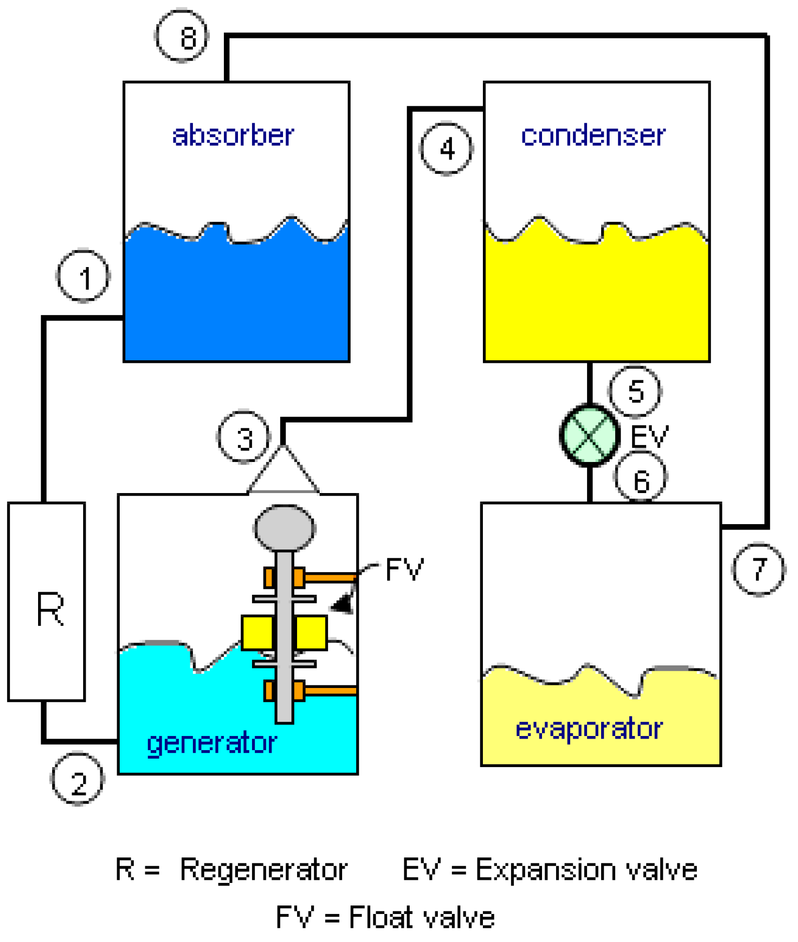
Figure 2 shows a schematic layout of the novel absorption refrigerator proposed here. This machine uses the same process vessels as the conventional absorption refrigerator shown in
Figure 1—namely, absorber, evaporator, condenser and generator, but without the need for an electrically powered solution circulation pump (P), in
Figure 1, or an expansion device or valve.
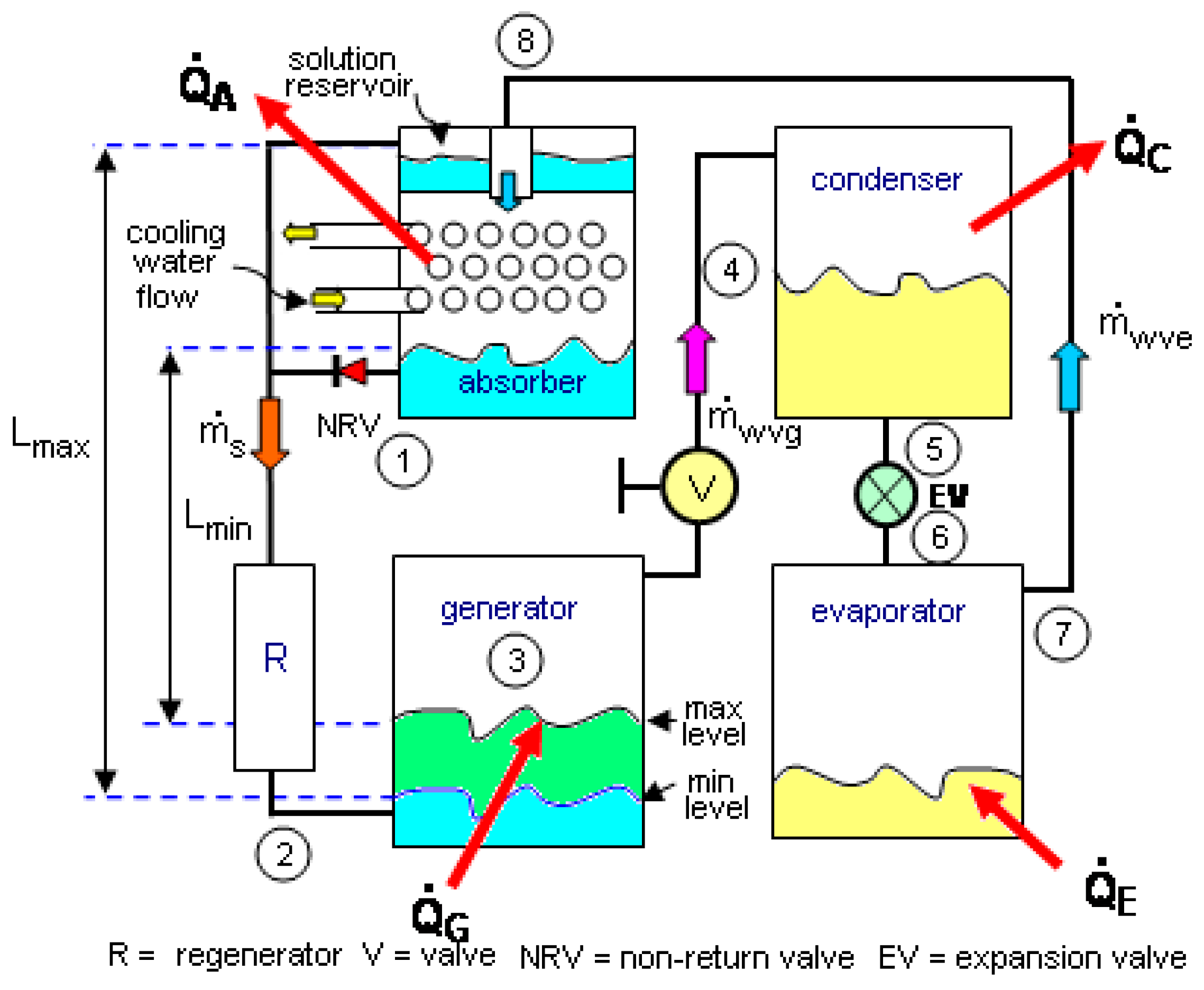
In the novel cycle, shown in
Figure 2, the evaporator operates in the same way as the conventional cycle shown in
Figure 1; that is, it continuously absorbs heat to create the necessary cooling effect by evaporating water at low pressure. This low pressure steam flows to the absorber vessel where it is continuously absorbed by the LiBr-H
2O solution. In the absorber, a quantity of concentrated solution is held in a reservoir at the top of the vessel. The solution flows slowly downwards over cooling coils, becoming increasingly more dilute as it absorbs water vapour in order to maintain the cooling effect at the evaporator. It is pointed out that the evaporator and absorber could be contained in the same low-pressure vessel, making its manufacture less complicated. The difference between the new cycle described in this paper and the conventional cycle lies in the mechanism used for circulating the solution between the absorber vessel and generator vessel.
The pumping process occurs in two stages. In the first stage, the solution collects at the bottom of the absorber vessel from where it flows downwards via a non-return valve (NRV) and a regenerative heat exchanger (R) into the vapour generator, where the solution is concentrated by distillation in the normal way. With no solution being pumped back to the absorber, the solution level in the generator rises until it reaches the upper (maximum) of two predetermined levels, as shown in
Figure 2. Meanwhile, steam raised in the generator during this first stage of the pumping process flows via an open valve (V) to the condenser vessel, where it is liquefied before returning to the evaporator by both gravity and excess of vapour pressure at the condenser.
The solution is able to flow from the absorber to the generator, which is at a higher pressure, because of the static head pressure created by the height of the liquid column between the surfaces in the absorber and generator. The system should be designed so that the flow will be maintained at the lowest level difference, L
min, shown in
Figure 2. In the following sample calculation, the height difference needed for all practical purposes is shown to be less than one metre.
Stage two of the pumping cycle begins once the solution level in the generator has reached its maximum mark. At this point, the steam valve (V) is closed, trapping steam inside the generator. With the steam-valve (V) closed, the pressure in the generator will rise. This pressure is great enough to overcome the static-head difference between the absorber and generator, causing the heated and concentrated solution to flow back towards the absorber vessel. The hot solution first passes through the regenerative heat exchanger, where it would be partially cooled, and then into the reservoir located at the top of the absorber vessel. The positioning of the non-return valve in the pipeline leading to the bottom of the absorber vessel prevents flow from entering the vessel at the bottom.
When the solution level in the generator has fallen to a predetermined minimum-level, shown in
Figure 2, the steam valve (V) would be re-opened and the cycle would again enter the first stage as previously described.
Throughout the second stage of the cycle, it is assumed that there is sufficient concentrated solution held in the reservoir to maintain the absorption process there.
The regenerative heat exchanger (R) in the solution pipeline between the generator and absorber is intended to reduce sensible heating and cooling effects at the generator and absorber, respectively. Such sensible heat transfer effects, if not reduced to the minimum possible within the limits of the second law of thermodynamics, can significantly lower the COP value of an absorption cycle refrigerator. Furthermore, because the generator temperature needs to be raised along with the solution temperature, when transferring liquid back to the absorber, it is particularly important that the generator is well insulated.
Although the solution flow between the absorber and generator is intermittent, the refrigeration effect will be constant. If the heat input at the generator is maintained at a constant value, then the coefficient of performance should not be too different to that of a conventional cycle machine. The following sample calculations help clarify this difference.
4. Simplified Theoretical Analyses
In the sample calculations below, the following general assumptions were made:
The heat rate to both the evaporator and generator are assumed to be constant throughout. In addition, the temperature of the absorber and condenser are assumed constant, although in practice, as shown by the experimental results, this is not the case. However, as shown by comparing the theoretical result with the experimental data, this assumption appears to provide adequate accuracy.
Refrigerant vapour leaving the evaporator is saturated.
The refrigerant flow from evaporator equals 5.5279 × 10
−4 kg/s (value measure by Stephens and Eames [
17]).
The flow through heat exchangers, steam valve and all connecting pipelines is frictionless.
The regenerator has an effectiveness of 50%.
1 L of solution is circulated between the generator and absorber during each pumping cycle, which is equal to 1.567 kg, as per Stephens and Eames data [
17].
The generator contains 4.7 kg (3 L) of solution when the steam valve just is closed, as per Stephens and Eames’ data [
17].
The surface level of the solution in the generator changes by 100 mm between maximum and minimum levels during the pumping cycle.
The above data match those used by Stephens and Eames [
17] in his experiments.
Input data: TG = 70 °C, TE = 10 °C, TA = 25 °C, TC = 40 °C.
From data tables [
3], the relevant properties of LiBr-H
2O at T
C = 40 °C and T
G = 100 °C are:
From data tables [
20] the relevant properties of steam are:
It should be noted that the solution pressure and temperatures given above as input data apply to the part of the cycle when the generator is filling with solution as described in
Section 4.1. The calculations in
Section 4.2 show that the generator temperature and pressure increase during the second-part of the cycle.
4.1. The First Part of the Cycle—Charging the Generator
During this part of the cycle steam valve “V” in
Figure 2 is open to allow steam produced at the generator to flow to the cooled condenser. During this half of the cycle, the rate of steam flow from evaporator (assuming a refrigeration effect of 1.33 kW) to absorber is given by
For steady state operation, the steam flow from the generator to the condenser will equal that from the evaporator to the absorber. In addition, note that,
. The flow of solution between absorber and generator is given by,
Recycle factor (
f) is an important parameter in determining the efficiency of an absorption cycle refrigerator. It measures the mass of solution that needs to be processed at the generator to produce given mass of steam at the evaporator and, by this, the refrigeration effect. In the present case
This result can be used to compare the performance of the present cycle with other absorption cycles.
Taking into account the heat-exchange effectiveness of the regenerator, the temperature of the solution entering the generator is given by
Noting that the solution concentration X
2 = X
A, then, from property data, the enthalpy of the solution entering the generator is given by
Applying the non-steady energy flow equation to the generator vessel gives
If the internal energy of the steam within the generator vessel is assumed negligible, and the specific internal energy of the solution within the vessel (u
S3) is constant, because T
G and X
G are both constant and because the flow-work (Pv) of the solution is small in comparison to its enthalpy, then
uS3 hS3, and therefore
Substituting this result into Equation (4) gives
During this part of the cycle, the quantity of water needed to boil from the 1.567 kg solution to change its concentration from 0.453 to 0.539 is given approximately by
The mass flow of steam from the generator is
. Therefore, the time taken to generate 0.135 kg of steam and to complete the first-part of the cycle is given by
The minimum head difference between the surface levels of the solution in the generator and absorber is given by
4.2. Second-Part of the Cycle—When the Steam Valve Is Closed
In this part of the cycle, the steam valve is closed and with the rate of heat addition to the generator maintained at the same value as in the first part of the cycle, i.e., 1.78 kW, the pressure in the vessel would increase, causing the solution to be flow back to the absorber. On its return, the concentrated solution would cool as it passes through the regenerator due to the temperature gradient within it.
For the purpose of this sample calculation, it is assumed that the liquid level in the generator would fall by 100 mm whilst 1.567 kg (1 L) of solution is returned into the absorber vessel. Referring to
Figure 2, the height through which the solution must be raised to reach the reservoir on top of the absorber increases from 600 mm at the start of this process, increasing to 825 mm when the solution has been transferred just when the steam valve is opened.
The pumping process occurs in two-stages: during the first stage, the temperature and pressure of the solution are raised at a constant concentration value of 0.539 from 70 °C and 7375 Pa, (the values at the end of the first part of the cycle described in
Section 4.1) to 74.9 °C and 9223 Pa, which is the pressure needed to raise the solution to a height of 600 mm from the maximum level in the generator to the absorber reservoir inlet. This process requires the enthalpy to change from 153.4 kJ/kg to 163.7 kJ/kg—a difference of 10.3 kJ/kg. If it is assumed that the quantity of solution leaving the generator during this process is negligible then, by the First Law of thermodynamics for a closed system, assuming no work is done, the heat input required is given by
Note it is assumed here that u h for the reason given earlier.
If the rate of heat addition to the generator is held constant throughout at 1.78 kW then the time needed to complete the initial heating process is approximately 27.2 s (=48.4/1.78).
During the second-part of the pumping cycle, it was assumed that the generator continued to absorb heat at the same rate (1.78 kW), causing the solution pressure to increase further in order to raise the solution to the maximum height in the absorber from the minimum height in the generator, equal to 825 mm. If losses are neglected, the generator pressure required to return the solution to be absorber will increase from 9223 Pa to 12,638 Pa at constant concentration of 0.539. This process requires the solution temperature and enthalpy to, respectively, increase to 82 °C and 178.6 kJ/kg.
Applying the First Law of thermodynamics to the generator gives
where in this case:
MG1 = mass of solution in the generator at the start of the second-part of the pumping cycle;
MG2 = mass of solution at the end of the pumping cycle;
h1 = enthalpy of the solution in the generator at the start of the second-part of the pumping cycle;
h2 = enthalpy of the solution in the generator at the end of the pumping cycle;
mout = mass of solution leaving the generator;
min = mass of solution entering the generator;
hin = enthalpy of solution entering the generator during the pumping process;
hout = enthalpy of solution leaving the generator.
For this process
, and, if it is assumed that
and
, then
From the given data,
MG2 = 3.1 kg,
MG1 = 4.7 kg. From property data tables,
Neglecting pressure losses in the regenerator and then connecting the pipeline, the work done in returning the solution to the absorber is equal to the change in its potential energy:
where
LAV = average height through which the solution is raised.
Substituting the above values into Equation (8) and solving for heat transfer gives QG = 58.1 kJ, which is the heat required to complete the second part of the pumping process.
If the heat rate remains at 1.78 kW, the time taken to return 1.567 kg of solution to the absorber would be approximately 32.6 s. Adding this result to the 27.2 s required to raise sufficient pressure in the generator after the steam valve was closed (for the first-stage of the pumping process), the total time required for the steam valve to be closed would be approximately 59.8 s.
During the second part of the pumping cycle, the temperature of the solution returning to the absorber from the regenerator (
T1) is given by
Because the evaporator cooling effect and generator heat input are assumed to be constant throughout, then the coefficient of performance for the theoretical cycle is given by
4.3. The Efficiency of the Pumping Process
The amount of energy used to pump the solution from the absorber to the generator is of interest because the process is essentially that of a heat engine in which heated is added at the generator and, after raising the solution to the height of the absorber heat, is rejected before the cycle is completed when the solution flows back to the generator. The results of the sample calculations described in this section showed, for the case being considered, that the total amount of heat input during the pumping cycle was 25.2 kJ, whilst the ideal useful work done was 10.95 J. The overall thermal efficiency of the pumping process was therefore 0.043%. Although this is inefficient, the only heat input at the generator not used to desorb the solution is the 10.95 J used to create the work of pumping and (in practice) any sensible heat loss at the generator. In addition, as the heat rate to the generator is constant, and if sufficient solution is held in the absorber reservoir to permit its continued operation whilst the steam valve is closed, then, in practice, the COP of the cycle should not be too different from that of the conventional cycle. A similar conclusion was drawn from a theoretical investigation of the novel cycle by Eames and Wu [
18].
5. Experimental Results
Stephens and Eames experimentally tested the absorption refrigerator shown schematically in
Figure 2 [
17]. The steam valve was hand operated, which allowed close control of the movement of the solution between the generator and absorber and vice versa.
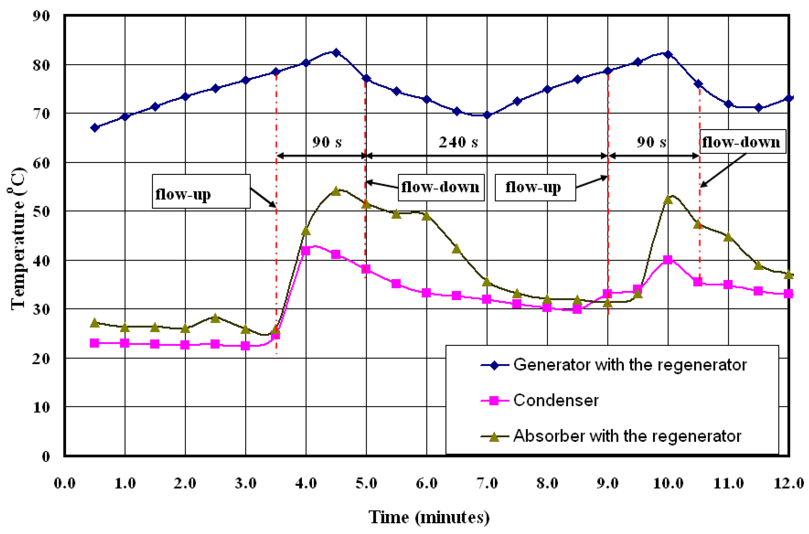
Figure 3 was drawn using Stephens and Eames’ recorded data. These show the variations in generator, absorber and condenser temperatures over a period of 16 minutes for two pumping cycles. In his original data, Stephens and Eames recorded only the times when the flow changed direction: he did not give the times when the steam valve was opened and closed. Therefore, from
Figure 3, when the flow was reported to be “up”, the steam valve must have been closed and when “down”, it was reported that the valve must have been open, but times at which the valve was opened and closed was not given. For example, the results in
Figure 3 showed that at the 3.5 min mark, the solution was observed to be flowing from the generator back to the absorber and, perhaps not unexpectedly, this was accompanied by a sudden rise in absorber temperature due to the influx of warm solution. However, the closing of the steam valve that produced this effect must have occurred before the solution began to flow back to the absorber for the reasons given in
Section 4.2, in which the generator pressure was allowed to rise in order to overcome the static head difference between it and the absorber before any upward flow would be possible.
At the 5 min mark in
Figure 3, the solution was observed to be flowing from the absorber to the generator. For this to happen, the steam valve must have been open in order to allow the pressure in the generator to fall. It is likely that this occurred at the 4.5 min mark, when the generator and pressure were at their highest. Not unexpectedly, therefore, there appears to have been a transient delay of approximately 30 s between the opening of the steam valve to the response of the solution.
When the solution flows back to the absorber from the generator, i.e., when the flow is upwards in
Figure 3, the condenser temperature is seen to increase (when the steam valve was closed) at the same time as the absorber temperature increased. This is due to the way in which the cooling water was piped to the condenser and absorber. During the experiment, as is usual practice, the cooling water was passed through the absorber and then the condenser—the two cooling coils being in series. Consequently, when the absorber was heated by the warm solution returning from the generator, some of this heat was transferred to the condenser, resulting in a rise in condensate temperature.
Referring to
Figure 3, the overall time available for the solution to flow back to the generator was observed experimentally to be not greater than 240 s, whilst the theoretical result calculated in
Section 4.1 for this part of the cycle was 243 s. This result is of interest. However, it is not clear from the experimental results at what time mark the downwards flow from the absorber to the generator actually ceased. Similarly, the experimental results show that the upward flow from the generator to the absorber occurred in a time not greater than 90 s, which compares with a theoretical value of 60 s calculated in
Section 4.2.
In the experiment, from which the data was used to produce
Figure 3, Stephens and Eames stated that the electric heater used to heat the generator had a power of 2 kW and that the average measured refrigerant flow was 5.5279 kg/s—the value for refrigerant flow used in the theoretical calculations. Based on these results, the estimated coefficient of performance for the refrigerator under test was:
This compares with the theoretical value of 0.73 given by Equation (9). This difference might be explained by heat loss at the generator.
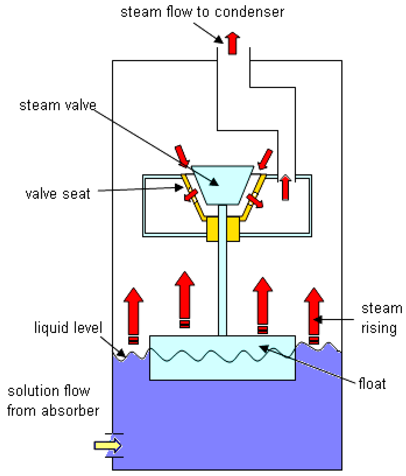
6. An Automatic Steam Valve
In their paper, Paurine et al. [
19] describe the construction and testing of a thermos-gravity VAR cycle and the operation of the automatic steam valve appears to be the reverse of what was required.
Figure 4 shows a schematic view of their valve.
The operation of the automatic valve shown in
Figure 4 would have resulted in either the solution in the generator needing to be cooled between pumping cycles, in order to allow the steam valve to open, or, if the machine was started with the solution in the generator vessel when heat was first applied, then the steam valve would probably not have opened: the solution contained in the vessel would be returned to the absorber without sufficient water being removed. The valve system described in the following paragraphs and diagrams aims to correct this error.
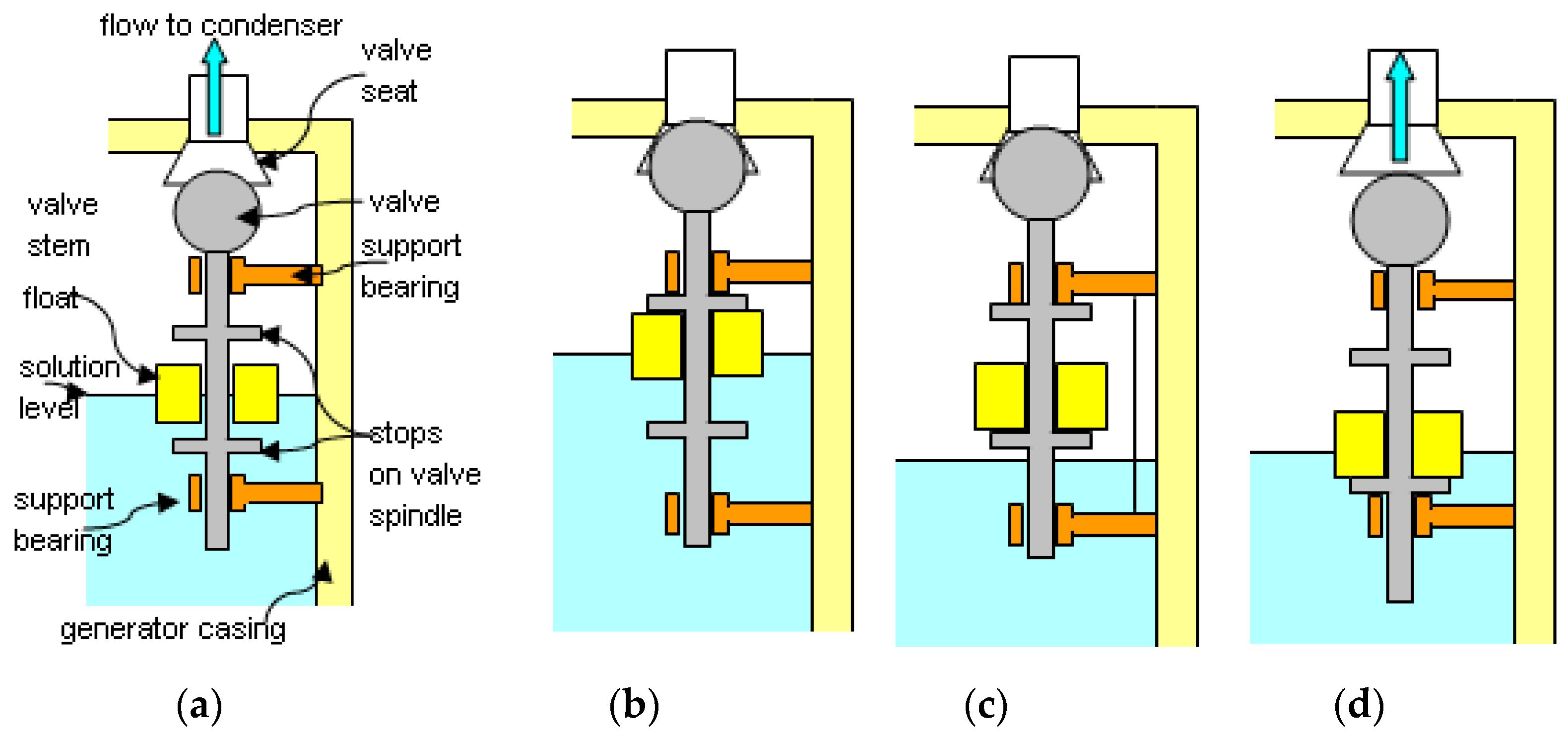
A schematic view of the automatic steam valve proposed by this author is shown contained within the generator in
Figure 5. The position of the valve is controlled by a float (FV).
Figure 6 illustrates the operation of the proposed steam valve. In
Figure 6a, the generator half filled with solution during the first stage of the pumping cycle. In this position, the generator pressure would be constant and steam would flow past the open valve and into the condenser. As the solution level in the generator vessel rises, the float would be lifted, and once it contacts the upper stop, the valve would be raised until it contacts its seat, as shown in
Figure 6b. With the valve on its seat, steam would not be able to exhaust from the generator and the pressure within it would rise and the cycle would enter the second part of the pumping cycle. Once the pressure in the generator was sufficient, the solution would be forced back via the regenerator to the absorber as described earlier. As the level in the generator now falls, the valve would be kept on its seat by the pressure difference across it and block the steam exhaust. Eventually, the solution level will fall sufficiently for the float to contact the lower stop, shown in
Figure 6c. The valve would need to be designed so that the weight of the float, unsupported by the solution, and that of the valve and valve-stem would be sufficient to pull the valve off its seat against the differential pressure across it. If this was not the case, then a pilot valve may be included to allow steam to bypass the valve in order to allow for equalising the vapour pressure across the valve to equalize and break the seal. This would allow the valve to come off its seat when the solution reached the lower level in the generator and allow the pumping cycle to re-enter its first part, shown in
Figure 6d, by permitting the generator vessel to refill with solution.
It should be noted that, in order to minimise pressure losses in the pipeline connecting the generator and condenser, it was recognised that the steam valve would need to be large. Proprietary steam valves of the correct volumetric flow capacity (m3/s) would be too physically heavy to operate the way that is desired and also such valves may be too expensive for small capacity refrigerators. Therefore, a relatively lightweight float control was proposed.

