Artificial Noise-Aided Physical Layer Security in Underlay Cognitive Massive MIMO Systems with Pilot Contamination


1
Department of Electrical and Computer Engineering, Southern Illinois University, Carbondale, IL 62901, USA
2
Information Theory and Applications Chair, Technische Universität Berlin, Berlin 10587, Germany
*
Author to whom correspondence should be addressed.
Entropy 2017, 19(7), 349; https://doi.org/10.3390/e19070349
Submission received: 2 June 2017
/
Revised: 23 June 2017
/
Accepted: 27 June 2017
/
Published: 10 July 2017
(This article belongs to the Special Issue Network Information Theory)
Abstract
:In this paper, a secure communication model for cognitive multi-user massive multiple-input multiple-output (MIMO) systems with underlay spectrum sharing is investigated. A secondary (cognitive) multi-user massive MIMO system is operated by using underlay spectrum sharing within a primary (licensed) multi-user massive MIMO system. A passive multi-antenna eavesdropper is assumed to be eavesdropping upon either the primary or secondary confidential transmissions. To this end, a physical layer security strategy is provisioned for the primary and secondary transmissions via artificial noise (AN) generation at the primary base-station (PBS) and zero-forcing precoders. Specifically, the precoders are constructed by using the channel estimates with pilot contamination. In order to degrade the interception of confidential transmissions at the eavesdropper, the AN sequences are transmitted at the PBS by exploiting the excess degrees-of-freedom offered by its massive antenna array and by using random AN shaping matrices. The channel estimates at the PBS and secondary base-station (SBS) are obtained by using non-orthogonal pilot sequences transmitted by the primary user nodes (PUs) and secondary user nodes (SUs), respectively. Hence, these channel estimates are affected by intra-cell pilot contamination. In this context, the detrimental effects of intra-cell pilot contamination and channel estimation errors for physical layer secure communication are investigated. For this system set-up, the average and asymptotic achievable secrecy rate expressions are derived in closed-form. Specifically, these performance metrics are studied for imperfect channel state information (CSI) and for perfect CSI, and thereby, the secrecy rate degradation due to inaccurate channel knowledge and intra-cell pilot contamination is quantified. Our analysis reveals that a physical layer secure communication can be provisioned for both primary and secondary massive MIMO systems even with the channel estimation errors and pilot contamination.
1. Introduction
Massive multiple-input multiple-output (MIMO) is currently being investigated as one of the key enabling technologies for the 5th generation wireless standard [1]. Specifically, in massive MIMO systems, very large antenna arrays are used for aggressive spatial multiplexing and focusing radiated energy towards desired spatial directions [2,3]. Thereby, massive MIMO can potentially provide unprecedented gains in spectral and energy efficiencies compared to conventional MIMO.
Confidentiality of transmitted information is one of the key challenges for system designers of next generation wireless communication networks [4]. To protect confidential communication against intruders and eavesdropper attacks, the concept of physical layer security [5,6,7,8,9] has recently attracted significant interest to complement current cryptographic approaches on higher layers. These techniques realize secure communication directly at the physical layer by exploiting the noisiness and imperfection of the wireless communication channel for degrading the quality of signal reception at eavesdroppers, and thereby prevent them from eavesdropping upon the confidential information from the intercepted signals [4].
Another concept that promises significant gains in performance for wireless communication networks are so-called cognitive radio networks. These cognitive networks allow secondary systems to access the licensed spectrum of the primary systems by exploiting the underlay spectrum sharing techniques, and thereby, mitigating the spectrum under-utilization of current wireless systems and significantly improving the spectral efficiency [10]. In cognitive radio systems, where the primary spectrum is an open medium to be accessed and utilized by the secondary systems, achieving end-to-end security is a crucial challenge to the system designs and configurations. Information theoretic secrecy provisioning for cognitive radio networks has been investigated, e.g., in [11,12].
In the event that the eavesdroppers intercept confidential signals passively, they do not transmit in order to conceal their existence. Therefore, the acquisition of the channel state information (CSI) of the eavesdropping channels at the massive MIMO base-stations (BSs) will be difficult. Although the null-space beamforming techniques can be effectively used in conventional MIMO BS for provisioning of physical layer security, constructing such sophisticated precoders at the massive MIMO BSs will be prohibitively complicated. Alternatively, artificial noise (AN) sequences can be exploited for massive MIMO BSs. In this context, massive MIMO techniques can be used in cognitive radio systems for provisioning physical layer security by exploiting the large antenna arrays at the BSs to simultaneously transmit confidential signals towards the legitimate user nodes and AN sequences towards eavesdroppers for perturbing the intercepted signals.
Notwithstanding that the massive MIMO techniques have received significant interest recently, little research exists on securing massive MIMO systems by exploiting physical layer security strategies. Next, some of the important contributions to the development of physical layer provisioning in massive MIMO systems are summarized. In [13], a secure transmission scheme for single-hop massive MIMO systems is investigated by deriving the secrecy rates and secrecy outage probabilities for perfect and imperfect CSI. Furthermore, in [14], the effects of linear precoding of data and AN in secure massive MIMO downlink are studied. Specifically, in [14], linear precoders that are based on matrix polynomials are proposed for both data and AN precoding, and consequently, the corresponding polynomial coefficients are optimized to minimize the sum mean-squared error and the AN leakage to the user nodes. In [15], optimal power allocation with security constraints in multi-user massive MIMO systems with distributed antennas is investigated. Moreover, in [16], the physical layer security and energy efficiency aspects are investigated for massive MIMO-enabled heterogeneous cloud radio access networks.
Although there is a symbiotic relationship between massive MIMO and cognitive radio networks to achieve a groundbreaking spectral and energy efficiencies for future wireless systems, facilitating secrecy at the physical layer of cognitive massive MIMO systems has not yet received any attention in the existing studies in the literature. To fill this gap, in this paper, a secure downlink transmission strategy is investigated for cognitive massive MIMO systems with underlay spectrum sharing in the presence of a passive multi-antenna eavesdropper. To this end, a secondary massive MIMO system is allowed to access the licensed spectrum of a primary massive system subject to an interference temperature constraint, which is the maximum tolerable co-channel interference (CCI) power at the primary system. Consequently, the secondary transmit power is constrained such that the CCI inflicted at the primary system due to secondary concurrent transmission is maintained below this interference temperature. The motive of the eavesdropper is to intercept the confidential transmissions of the primary or secondary systems. By assuming that the eavesdropper’s CSI is unavailable, AN sequences are generated at the primary base-station (PBS) for provisioning physical layer security by exploiting the additional degrees-of-freedom offered by its massive antenna array. The construction of null-space-based AN shaping precoders at the PBS is prohibitively complicated due to its massive antenna array, and hence, random AN shaping matrices are advocated. Furthermore, zero-forcing (ZF) based precoders are used at the PBS and the secondary base-station (SBS).
The uplink channels of the primary and secondary systems are estimated at the corresponding BSs by using pilots transmitted by the primary user nodes (PUs) and secondary user nodes (SUs), respectively. The number of orthogonal pilot sequences is limited and depends on the coherence interval of the wireless channels [2]. Hence, the same pilot sequence is shared among both PUs and SUs for minimum mean square error (MMSE) channel estimation. Nevertheless, a normalized pseudo-inverse of a complex Gaussian random matrix is used for AN shaping at the PBS, and thereby, the burden of estimating the eavesdropper’s channels is avoided.
The performance of the aforementioned system set-up is investigated by deriving the achievable secrecy rates in closed-form for both imperfect and perfect channel state information (CSI) cases. The impacts of the numbers of PBS and SBS antennas are investigated in the context of provisioning physical layer secure transmission for cognitive massive MIMO systems. Furthermore, the detrimental effects of intra-cell secondary interference, channel estimation errors, intra-cell pilot contamination, and AN leakage into the desired signals at the PUs and SUs are investigated for the imperfect and perfect CSI cases. Thereby, the achievable secrecy rate degradation due to intra-cell pilot contamination and inaccurate channel estimation is quantified.
Notation: , , , and denote the conjugate, transpose, Hermitian-transpose, and the element of a matrix , respectively. is the expectation and the operator ⊗ denotes the Kronecker product.
2. System, Channel, and Signal Models
In this section, the system, channel, and signal models of a cognitive multi-user massive MIMO system are presented.
2.1. System and Channel Model
We consider a cognitive multi-user MIMO network with underlay spectrum sharing (see Figure 1). A multi-user secondary MIMO system is underlaid within a primary multi-user MIMO system. The secondary system shares the same licensed frequency spectrum of the primary system by exploiting the concepts of cognitive underlay spectrum sharing [10]. The primary system consists of an -antennas PBS and K single-antenna PUs. In the secondary system, M single-antenna SUs are served by an -antenna SBS. The ratio between the numbers of BS antennas at the primary and secondary systems is defined as . The numbers of antennas at the PBS and SBS can grow without limit compared to the numbers of PUs and SUs, () and (), while keeping a fixed ratio . Moreover, an -antenna eavesdropper seeks passively to eavesdrop upon the information transmitted to user nodes, either in the primary or secondary system.
Let be the channel matrix between the PBS and PUs, and is the channel matrix between the SBS and SUs. Here, and are the interference channel matrices between the SBS and PUs and between the PBS and SUs, respectively. Moreover, is the channel matrix between the PBS and the eavesdropper, and is the channel matrix between the SBS and the eavesdropper. For the sake of the brevity of exposition, all the aforementioned channels can be correspondingly defined in the following general expression:
where , models the independent small-scale Rayleigh fading, and diagonal matrix captures the path-loss.
2.2. Uplink Training and Channel Estimation
In massive MIMO systems, the uplink CSI is estimated at the BS from the uplink pilot sequences transmitted by the user nodes during the training period of the coherence interval (T). Then, the downlink channel is obtained from the uplink CSI by exploiting the channel reciprocity in time-division duplex (TDD) mode of operation. Here, for the sake of exposition, we assume that the numbers of PUs and SUs are the same (). Therefore, all the PUs and SUs transmit simultaneously () symbols of T as pilot sequences. The received pilot signals at the PBS and SBS are given by:
respectively, where is the average transmit power of each pilot symbol, is a pilot symbol matrix transmitted by the PUs, where is a unitary matrix () satisfying , and is an pilot symbol matrix transmitted by the SUs, where is a unitary matrix () satisfying . Furthermore, and are additive white Gaussian noise (AWGN) matrices at the PBS and SBS with independent and identically distributed (i.i.d.) elements, respectively. In (2), all pilot sequences are non-orthogonal, i.e., the primary and secondary systems share the same pilot sequences, i.e., , which practically represents the worst-case scenario. Thus, the uplink channel estimates at the PBS and SBS are affected by pilot contamination, then the MMSE channel estimate of can be derived as [3]:
where is an estimation noise matrix consisting of i.i.d. elements. In (3), and are statistically independent. Let be the estimation error matrix of . By using MMSE properties, the channel can be decomposed as:
From the property of MMSE estimation, and are independent. Furthermore, the rows of and are mutually independent and distributed as and , respectively, where is a diagonal matrix, whose k-th diagonal element is:
Next, by applying steps similar to those used for deriving (3), the MMSE channel estimate of can be derived as follows:
where is a noise matrix with i.i.d. random variables. Both and in (6) are statistically independent. The estimation error matrix of at SBS is denoted by , where the channel can be decomposed as:
Again, and are independent. Also, the rows of and are mutually independent and distributed as and , respectively, where is a diagonal matrix whose m-th diagonal element is given by:
2.3. Signal Model
In this section, the signal model is presented, and thereby the signal-to-interference-plus-noise ratios (SINRs) are derived.
2.3.1. Transmit Power Constraint for the SBS
In underlay spectrum sharing cognitive systems, the power of the secondary transmissions is constrained such that the total interference power inflicted at the primary receivers is less than a predefined interference temperature [10]. Therefore, the transmit power of the SBS is constrained as follows:
where is the maximum transmit power at the SBS. Furthermore, is the primary interference temperature, which is the maximum tolerable interference level that the PUs can endure without compromising the quality-of-service. In (9), is the ZF precoder at the SBS and is defined as:
where is a power normalization factor at the SBS and is defined as [17]:
For a finite number of antennas at the SBS, the transmit power constraint can be re-written as:
where is approximated as (see Appendix A.1 for derivation):
Next, the asymptotic transmit power constraint at the secondary system for infinitely many BS antenna can be derived by letting go to infinity in (12) as follows:
Remark 1.
As , the secondary transmit power constraint (12) asymptotically becomes independent of the interference temperature of the primary system. Consequently, the secondary system with underlay spectrum sharing can be operated independent of the primary system, and hence, the secondary system can be asymptotically operated at its maximum transmit power level.
2.3.2. Signal Model for the Primary System
It is assumed that the eavesdropper’s CSI is unavailable at both PBS and SBS. Consequently, the PBS transmits an AN sequence for degrading the eavesdropper’s ability to decode the signals transmitted to its PUs. To this end, the additional degrees-of-freedom offered by the large antenna array at the PBS are used to transmit this AN. Thus, the PBS transmits both confidential data and AN by using linear precoders in the downlink. In this context, the transmitted signal vector at the PBS can be written as:
where and are the transmit powers allocated for confidential data and AN, respectively. In (15), is the precoder used for pre-processing the confidential data at the PBS. Furthermore, is the AN shaping matrix at the PBS, and is the AN vector and defined as . In particular, is designed based on the ZF criterion as:
where is a normalization constant, and is defined as:
The construction of the AN shaping matrix can be described as follows: In conventional MIMO systems, the AN shaping matrix () can be constructed by computing the null space of the desired channel matrix (). In this context, the performance degradation due to the leakage of AN into desired signals can be mitigated. However, for a massive MIMO PBS, the computation of the null space based precoders is prohibitively complicated. Hence, can be constructed as the pseudo-inverse of a random matrix with mutually independent Gaussian random vectors. To this end, the AN shaping matrix can be defined as follows:
where , , and is defined as:
In particular, is designed as a normalized version of the pseudo-inverse of . Therefore, the aforementioned choice (18) facilitates the mathematical tractability of the asymptotic analysis.
The received signal vector at the PUs can be written as:
where and are the transmitted signal vectors of the PBS and SBS satisfying and , respectively. Furthermore, is the AWGN vector at the PUs satisfying . In (20), the first term accounts for the desired signal transmitted towards the PUs. The second term captures the intra-cell interference due to the concurrent secondary transmissions in the same frequency band. Moreover, the third term represents the AN leakage into the PUs.
Then, the received signal at the k-th PU (i.e., the k-th element of ) can be expressed as:
where and are the k-th columns of and , respectively, and and are the k-th element of and , respectively.
2.3.3. Signal Model for the Secondary System
The SUs are served by the SBS, where the received signal at the SUs is:
where the first term represents the desired signal at the SUs. The second term captures the intra-cell interference from the concurrent primary transmissions. The third term accounts for the AN leakage into the SU’s reception. Moreover, models the AWGN vector at the SUs satisfying . The received signal at the m-th SU can be written as:
where and are the m-th columns of and , respectively, and and are the m-th element of and , respectively.
2.3.4. Signal Model for the Eavesdropper
The eavesdropper is interested in eavesdropping upon the confidential data transmitted to either PUs or SUs. For the sake of completeness, two cases, in which the eavesdropper intercepts (1) the k-th PU’s signal and (2) the m-th SU’s signal, are investigated. To this end, a generic expression for the received signal at the eavesdropper can be written as:
where is the AWGN vector at the eavesdropper satisfying . In (24), the first term corresponds to the signal transmitted by the PBS, the second term accounts for the AN leakage, and the third term captures the signal transmitted by the SBS. Then, the k-th PU signal intercepted at the eavesdropper can be re-written as:
Whereas, the m-th SU signal intercepted at the eavesdropper can be re-written as:
2.4. Achievable Rate Analysis
In this subsection, the achievable rate expressions at the PUs and SUs are derived by using the worst-case Gaussian noise approximation technique. This technique is widely used in sum rate analysis in wireless systems [17,18], and basically represents a lower bound of what can be achieved in practice. Accordingly, by using (21), the received signal at the k-th PU can be re-written as:
where the first term accounts for the desired signal and represents the effective noise, which is given by:
In (27), the desired signal and the effective noise are uncorrelated. The worst-case uncorrelated additive noise is independent Gaussian noise having the same variance, hence, the achievable rate at the k-th PU can be derived as:
where , , and account for the primary inter-user interference, intra-cell interference due to concurrent secondary transmissions, and the AN leakage towards the k-th PU, respectively, and they are defined as:
Similarly, by using (23), the received signal at the m-th SU can be re-written as:
where the first term represents the desired signal and is the effective noise, and is given by:
Hence, the achievable rate at the m-th SU can be derived as:
where , , and represent the secondary inter-user interference, the CCI from SBS transmissions, and the AN leakage towards the m-th SU, respectively, and they are defined as:
3. Secrecy Rate Analysis
An achievable secrecy rate of the k-th PU is given by the difference between channel capacities of the PBS to PU channel and the PBS to eavesdropper channel. Thus, the achievable secrecy rate at the k-th PU is:
where .
A lower bound for the achievable rate at the k-th PU can be derived from (29) as (see Appendix A.2 for the derivation):
The eavesdropper’s rate, on the other hand, cannot be lower bounded, since in that case the obtained secrecy rate is no longer a lower bound. Thus, the ergodic rate of the k-th PU signal leaked into the eavesdropper is computed as , where is a closed-form expression for the SINR of the k-th PU signal intercepted at the eavesdropper, which is derived from (24) as (by assuming eavesdropper is able to mitigate inter-pair interference [13]):
Similarly, the achievable secrecy rate of the m-th SU is:
where is an achievable rate of the m-th SU and its lower bound is derived by following steps similar to those used for deriving (36) as:
Furthermore, is the information leakage rate to the eavesdropper for decoding the m-th SU’s confidential information, and can be computed as: , where is the SINR expression of the m-th SU signal intercepted at the eavesdropper, which is derived from (24) as:
4. Asymptotic Secrecy Rate Analysis
In this section, the asymptotic secrecy rates are derived whenever the numbers of antennas at the PBS and SBS grow without limit while keeping a fixed ratio . In this context, the pilot transmit power is assumed to be fixed, whereas the transmit powers at the PBS and SBS are scaled as follows: , , and , where , , and are constants [3]. Hence, by letting in (35), the corresponding achievable secrecy rate for the case in which the eavesdropper intends to intercept the confidential signal transmitted to the k-th PU can be derived as (see Appendix A.3 for the derivation):
The corresponding achievable secrecy rate for the case in which the eavesdropper is intercepting the confidential signal transmitted to the m-th SU can be derived, by letting in (38), as (see Appendix A.3 for the derivation):
Remark 2.
In particular, the transmit powers of the payload data at both BSs and the transmit power of AN sequence at the PBS can be scaled inversely proportional to the number of BS antennas without incurring any performance penalty. Moreover, the asymptotic secrecy rates are independent of the fast fading components of the corresponding wireless channels.
5. Performance Analysis for Perfect CSI
For further investigations, the performance analysis of the considered system is provided in this section for the idealistic scenario of having perfect CSI, i.e., and . Hence, the amounts of performance degradation due to inaccurate channel knowledge and pilot contamination are quantified and compared. To this end, the ZF detectors at the PBS and SBS can be constructed by assuming the availability of the genie-aided perfect CSI as follows:
5.1. Secondary Transmit Power Constraint for Perfect CSI Case
The secondary transmit power constraint for perfect CSI can be re-written as:
Next, the maximum transmit power at the SBS is scaled inversely proportional to the number of antennas as . The secondary transmit power constraint can then be rewritten as:
5.2. Achievable Rate Analysis for Perfect CSI Case
In this subsection, the achievable rate at the PUs, SUs, and eavesdropper are derived by replacing and with and in (20), (22), and (24), respectively. To this end, by using (20), the achievable rate at the k-th primary user node can be computed as , where is:
Similarly, by using (22), the achievable rate at the m-th secondary user node can be derived as , where is given by
Next, by using (24) and by assuming the eavesdropper is capable of fully mitigating the inter-substream interference, the information leakage rate to the eavesdropper for decoding the k-th PU’s confidential information is computed as , where is the SINR expression of the k-th PU signal intercepted at the eavesdropper, which is given by:
Similarly, the rate of the m-th SU signal leaked into the eavesdropper is computed as , where is a closed-form expression for the SINR of the m-th SU signal intercepted at the eavesdropper, which is derived from (24) as:
5.3. Asymptotic Secrecy Rate Analysis for Perfect CSI Case
In this subsection, the asymptotic secrecy rate expressions are derived for both primary and secondary systems when the numbers of antennas at the PBS and SBS grow without limit, while keeping a fixed ratio . In this context, the transmit powers at the PBS and SBS are scaled inversely proportional to the number of BS antennas as , , and , where , , and are constants. Whenever and grow without bound, the corresponding achievable secrecy rate for the case in which the eavesdropper intends to intercept the confidential signal transmitted to the k-th primary user is derived as (see Appendix B for the derivation):
Similarly, the corresponding asymptotic secrecy rate for the case in which the eavesdropper intends to intercept the confidential signal transmitted to the m-th SU is given by:
6. Numerical Results
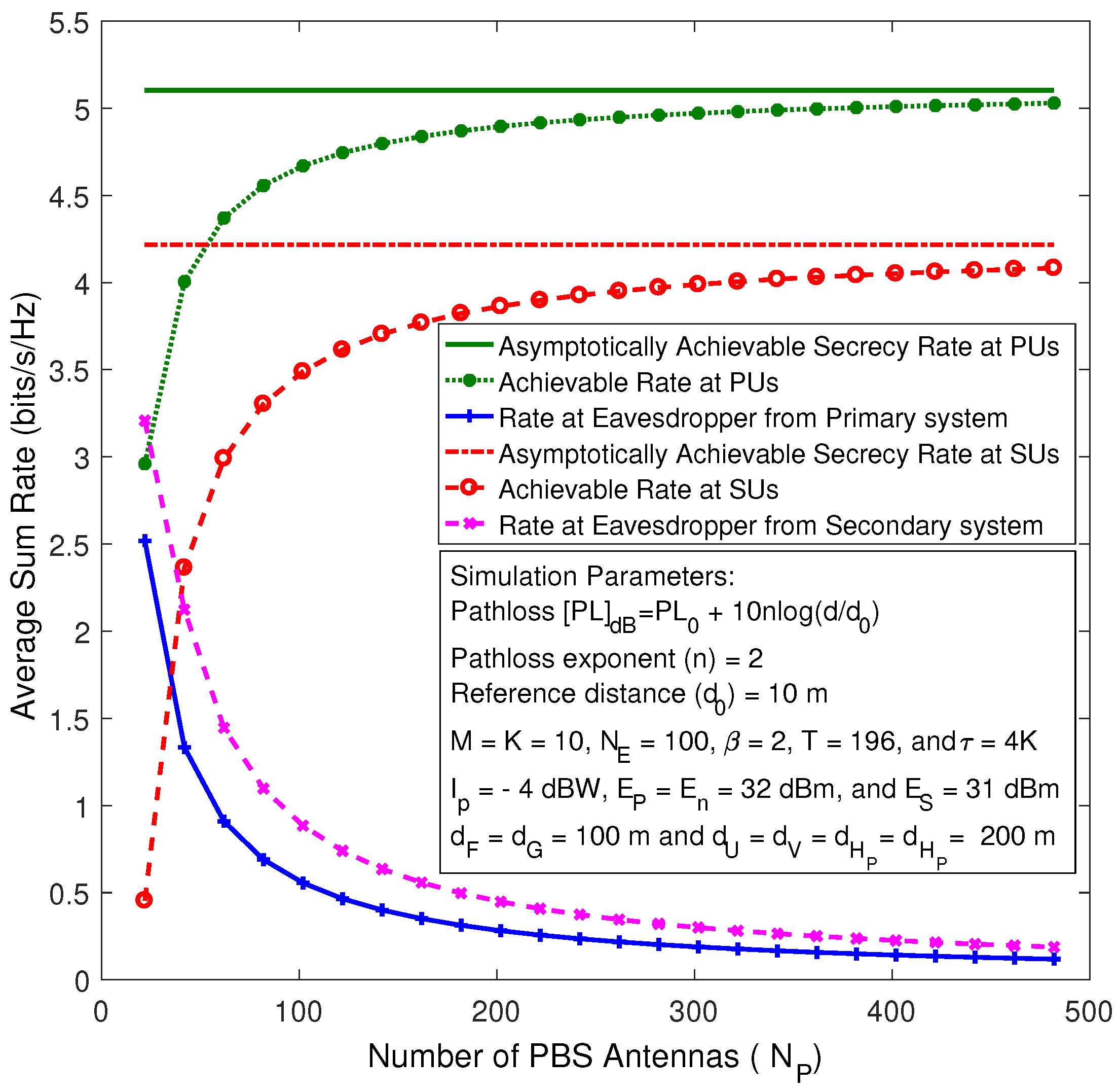
In Figure 2, the achievable secrecy sum rates at the PUs and SUs are plotted. Furthermore, the information leakage rates to the eavesdropper from the primary and secondary transmissions are plotted against while keeping fixed. The exact (simulation) curves are generated by using (29), (33), (37), and (40) through Monte-Carlo simulations. Moreover, the asymptotic secrecy rate is plotted by using (41) and (42). Figure 2 reveals that the corresponding information leakage rates to the eavesdropper asymptotically vanish when and . Hence, the secrecy rate asymptotically approaches the achievable rate at the user nodes. Therefore, the intra-cell pilot contamination effects in cognitive massive MIMO systems do not hinder the use of random pseudo-inverse based AN shaping matrices.
To investigate the impact of the primary interference temperatures on the secondary system transmissions for the imperfect and perfect CSI cases, the transmit power constraint of the SUs is plotted, in Figure 3, against the number of PBS antennas for two different primary interference temperatures. The asymptotic transmit power constraints are plotted by using the asymptotic analysis in (14) and (47), while the exact curves are plotted by using Monte-Carlo simulations. Figure 3 clearly reveals that the transmit power of the secondary system approaches its allowable peak value when the number of PBS antennas grows large. However, the rate of asymptotic convergence depends on the CSI assumption and the primary interference temperature. Specifically, the curves corresponding to imperfect CSI exhibit the lowest rate of asymptotic convergence compared to the perfect CSI case. Moreover, the asymptotic rate of convergence decreases whenever the primary interference temperature decreases.
In Figure 4, the transmit power constraint at the secondary system is plotted versus the number of PBS antennas by varying the number of user nodes for the cases of imperfect and perfect CSI. Figure 4 shows that the secondary system transmit power asymptotically approaches its peak level as the number of PBS antennas grows without bound, irrespective of the number of user nodes. Nevertheless, the rate of asymptotic convergence decreases when the numbers of user nodes increase. Therefore, the secondary system can asymptotically be operated at its peak transmit power, regardless of the number of user nodes and primary interference temperature, whenever the PBS is equipped with a very large antenna array.
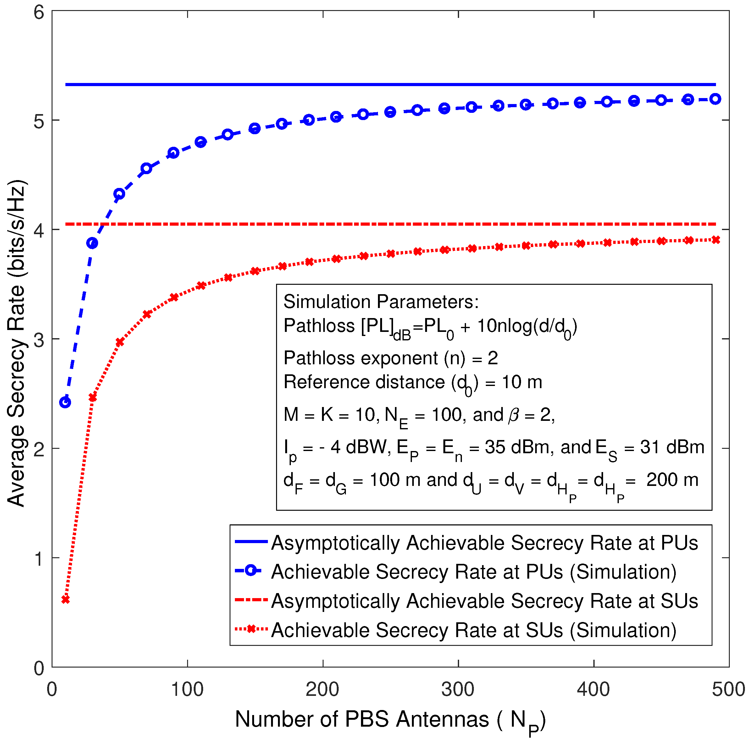
Figure 5 depicts the achievable secrecy rate of the primary and secondary systems against the number of PBS antennas for the perfect CSI case. The asymptotic secrecy rate curves are plotted by using (52) and (53), whereas the exact sum rate curves are plotted by using Monte-Carlo simulations. As shown in Figure 5, for a fixed number of antennas at the eavesdropper (), the achievable secrecy rates at the primary and secondary systems go up gradually with the growing of and until they approach their corresponding asymptotic curves, which basically means the capability of the eavesdropper decreases and eventually vanishes whenever the number of antennas grows large.
7. Conclusions
In this paper, a secure communication model for cognitive multi-user massive MIMO networks with underlay spectrum sharing has been proposed and analyzed. The extra degrees-of-freedom provided by the massive MIMO have been exploited to transmit AN sequences to incapacitate the eavesdropper’s ability to decode the confidential data. The asymptotic achievable secrecy rates of this system model have been derived in closed form for imperfect and perfect CSI cases. Thereby, the detrimental effects of AN leakage into the desired signals and performance degradation due to pilot contamination have been investigated. Random AN shaping matrices can be employed in this model, and avoid the complication of designing a null-space based precoder, without any asymptotic performance penalty. The transmit power allocated for the AN sequence can be scaled down inversely proportional to the number of PBS antennas, and hence, a significant energy efficiency gain can be attained. The secondary transmit power constraint becomes independent of the primary interference temperature, and consequently, the secondary system can be operated independent of the primary system in the limit of infinitely many BS antennas. The asymptotic information leakage into the eavesdropper vanishes whenever the numbers of PBS and SBS antennas grow without bound, and hence, the asymptotic secrecy rates become independent of the BS-to-eavesdropper channels. Therefore, our work brings some valuable designing insights on physical layer security analysis in cognitive massive MIMO networks, and proposes an elegant mechanism for strengthening the security of communications against the potential attacks in the cognitive radio networks.
Author Contributions
All authors contributed equally to this work.
Conflicts of Interest
The authors declare no conflict of interest.
Appendix A. Derivations for the Performance Metrics for Imperfect CSI Case
In this appendix, derivations for the secrecy performance metrics are outlined. The achievable rates at the primary and secondary systems, and the transmit power constraint are derived arbitrarily for many antennas at the PBS and SBS. The asymptotic secrecy rates corresponding to the primary and secondary systems are derived when the numbers of antennas at the BS grow large.
Appendix A.1. Transmit Power Constraint at the Secondary System
The transmit power constraint in (9) can be re-written as:
where . To begin with, and are dependent; the channel , by using (6), can be re-written as:
where,
Then, by using (A2), can be derived as follows:
Here, from (10), , since , the law of large numbers can be used to do this approximation, , and consequently, . Moreover, the term , by using (6) can be simplified as . Thus,
By substituting (A5) into (9), the transmit power constraint for finitely many SBS antennas can be derived as shown in (12).
Appendix A.2. for Finite Antenna Numbers
The achievable rate at the k-th PU is derived when both BSs are equipped with finite antenna numbers. From (29) the desired power can be derived as by invoking (16) and (4) as follows:
Then, the desired power for the k-th PU can be re-written as:
where is the k-th column of , since and are uncorrelated, and is a zero-mean random variable, . Thus,
Next, the first term of the effective noise in (29), , can be derived by using (A7) and (A8) as:
where is a central Wishart matrix with degrees of freedom and covariance matrix , where [19].
The derivations for the remaining terms of the effective noise in (30) are given in the following:
- Deriving : Similarly, can be derived as:
Appendix A.3. Asymptotic Achievable Rate at the Eavesdropper
To evaluate the asymptotic achievable rate at the eavesdropper when the PBS and SBS are deploying massive antenna arrays, the following identities are recalled from [20].
For a random matrix having elements of zero mean and unit variance, as the column vectors of become orthogonal, and hence, the following identity holds:
Also, whenever a random matrix is independently distributed with , the following identity holds:
By first letting and , and then by substituting (10), (16), and (18) into (37), the SINR of the k-th PU signal intercepted at the eavesdropper can be re-written as:
Next, by letting and in (A17) and then by invoking (A15) and (A16), it can be shown that:
Appendix B. Derivations the Asymptotic Performance Metrics for Perfect CSI
In this appendix, the derivations of the asymptotic rates of primary and secondary systems with perfect CSI are outlined. To begin with, by letting , , and and then by substituting (43), (44) and (18) into (48), the end-to-end SINR at the k-th PU can be re-written as:
Next, by letting and in (A21) and then by using (47), (A15) and (A16), the asymptotic SINR for the k-th PU can be written as:
Moreover, by using steps similar to those used for deriving (A21), the end-to-end SINR at the m-th SU can be re-written as:
Again, by letting and in (A23) and then by using (47), (A15) and (A16), the asymptotic SINR for the m-th SU can be written as:
Furthermore, the end-to-end SINR at the eavesdropper, who is interested in intercepting the signal of the k-th PU, can be obtained by substituting (44), (43) and (18) into (37) as follows:
Next, by letting and in (A25) and then by using (47), (A15) and (A16), the asymptotic SINR at the eavesdropper, who is interested in intercepting the signal of the k-th PU, can be derived as:
Similarly, by substituting (44), (43) and (18) into (40), the end-to-end SINR at the eavesdropper, who is interested in intercepting the signal of the m-th SU, can be re-written as:
Again, by letting and in (A27) and then by using (47), (A15) and (A16), the asymptotic SINR at the eavesdropper, who is interested in intercepting the signal of the m-th SU, can be derived as:
Next, by using (35), an achievable asymptotic secrecy rate at the k-th PU can be written as:
By substituting (A22) and (A26) into (A29), the desired asymptotic secrecy rate can be derived as given in (52).
References
- Boccardi, F.; Heath, R.; Lozano, A.; Marzetta, T.; Popovski, P. Five disruptive technology directions for 5G. IEEE Commun. Mag. 2014, 52, 74–80. [Google Scholar] [CrossRef]
- Marzetta, T.L. Noncooperative Cellular Wireless with Unlimited Numbers of Base Station Antennas. IEEE Trans. Wirel. Commun. 2010, 9, 3590–3600. [Google Scholar] [CrossRef]
- Ngo, H.Q.; Larsson, E.G.; Marzetta, T.L. Energy and Spectral Efficiency of Very Large Multiuser MIMO Systems. IEEE Trans. Commun. 2013, 61, 1436–1449. [Google Scholar]
- Yang, N.; Wang, L.; Geraci, G.; Elkashlan, M.; Yuan, J.; di Renzo, M. Safeguarding 5G wireless communication networks using physical layer security. IEEE Commun. Mag. 2015, 53, 20–27. [Google Scholar] [CrossRef]
- Liang, Y.; Poor, H.V.; Shamai, S. Information Theoretic Security. Found. Trends Commun. Inf. Theor. 2009, 5, 355–580. [Google Scholar] [CrossRef]
- Bloch, M.; Barros, J. Physical-Layer Security: From Information Theory to Security Engineering; Cambridge University Press: Cambridge, UK, 2001. [Google Scholar]
- Kapetanovic, D.; Zheng, G.; Russek, F. Physical layer security for massive MIMO: An overview on passive eavesdropping and active attacks. IEEE Commun. Mag. 2015, 53, 21–27. [Google Scholar] [CrossRef]
- Schaefer, R.F.; Boche, H.; Khisti, A.; Poor, H.V. Information Theoretic Security and Privacy of Information Systems; Cambridge University Press: Cambridge, UK, 2017. [Google Scholar]
- Poor, H.V.; Schaefer, R.F. Wireless physical layer security. Proc. Natl. Acad. Sci. USA 2016, 114, 19–26. [Google Scholar] [CrossRef] [PubMed]
- Goldsmith, A.; Jafar, S.A.; Maric, I.; Srinivasa, S. Breaking Spectrum Gridlock with Cognitive Radios: An Information Theoretic Perspective. Proc. IEEE 2009, 97, 894–914. [Google Scholar] [CrossRef]
- Liang, Y.; Somekh-Baruch, A.; Poor, H.V.; Shamai, S.; Verdú, S. Capacity of cognitive interference channels with and without secrecy. IEEE Trans. Inf. Theor. 2009, 55, 604–619. [Google Scholar] [CrossRef]
- Gabry, F.; Zappone, A.; Thobaben, R.; Jorswieck, E.A.; Skoglund, M. Energy Efficiency Analysis of Cooperative Jamming in Cognitive Radio Networks with Secrecy Constraints. IEEE Wirel. Commun. Lett. 2015, 4, 437–440. [Google Scholar]
- Zhu, J.; Schober, R.; Bhargava, V. Secure Transmission in Multicell Massive MIMO Systems. IEEE Trans. Wirel. Commun. 2014, 13, 4766–4781. [Google Scholar] [CrossRef]
- Zhu, J.; Schober, R.; Bhargava, V.K. Linear Precoding of Data and Artificial Noise in Secure Massive MIMO Systems. IEEE Trans. Wirel. Commun. 2016, 15, 2245–2261. [Google Scholar] [CrossRef]
- Guo, K.; Guo, Y.; Ascheid, G. Security-Constrained Power Allocation in MU-Massive-MIMO with Distributed Antennas. IEEE Trans. Wirel. Commun. 2016, 15, 8139–8153. [Google Scholar] [CrossRef]
- Wang, L.; Wong, K.K.; Elkashlan, M.; Nallanathan, A.; Lambotharan, S. Secrecy and Energy Efficiency in Massive MIMO Aided Heterogeneous C-RAN: A New Look at Interference. IEEE J. Sel. Top. Signal Process. 2016, 10, 1375–1389. [Google Scholar] [CrossRef]
- Yang, H.; Marzetta, T.L. Performance of Conjugate and Zero-Forcing Beamforming in Large-Scale Antenna Systems. IEEE J. Sel. Areas Commun. 2013, 31, 172–179. [Google Scholar] [CrossRef]
- Hassibi, B.; Hochwald, B.M. How much training is needed in multiple-antenna wireless links? IEEE Trans. Inf. Theor. 2003, 49, 951–963. [Google Scholar] [CrossRef]
- Tulino, A.M.; Verdú, S. Random matrix theory and wireless communications. Found. Trends Commun. Inf. Theor. 2004, 1, 1–128. [Google Scholar] [CrossRef]
- Cramer, H. Random Variables and Probability Distributions; Cambridge University Press: Cambridge, UK, 1970. [Google Scholar]
Figure 1.
System model for a multi-user cognitive massive multiple-input multiple-output (MIMO) network in the presence of a multi-antenna eavesdropper. PBS: primary base station; SBS: secondary base station; PU: primary user node; SU: secondary user node.
Figure 1.
System model for a multi-user cognitive massive multiple-input multiple-output (MIMO) network in the presence of a multi-antenna eavesdropper. PBS: primary base station; SBS: secondary base station; PU: primary user node; SU: secondary user node.
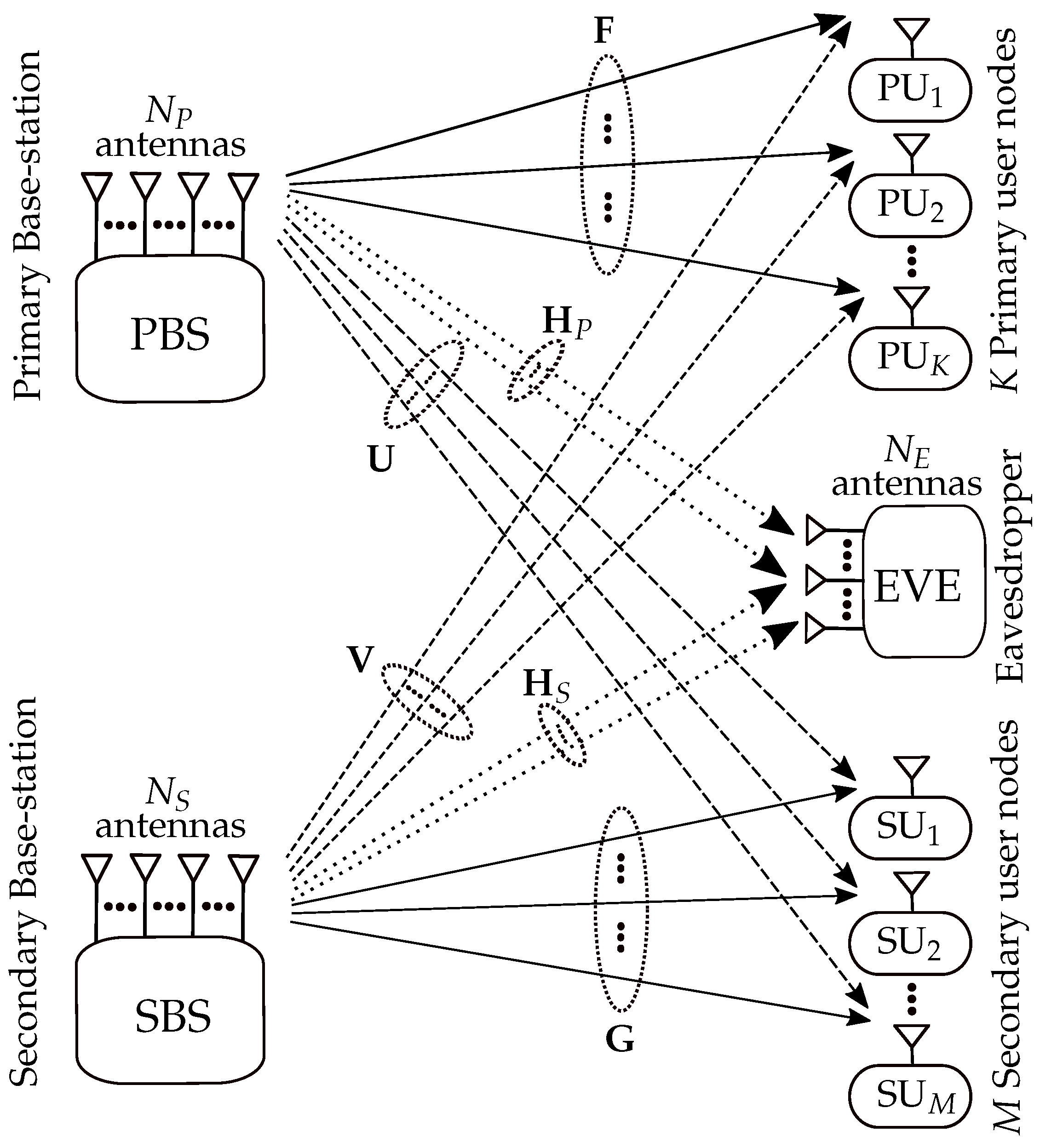
Figure 2.
The achievable secrecy rates versus the number of PBS antennas for imperfect channel state information (CSI) case.
Figure 2.
The achievable secrecy rates versus the number of PBS antennas for imperfect channel state information (CSI) case.

Figure 3.
The transmit power constraint of the secondary system versus the number of PBS antennas by varying .
Figure 3.
The transmit power constraint of the secondary system versus the number of PBS antennas by varying .
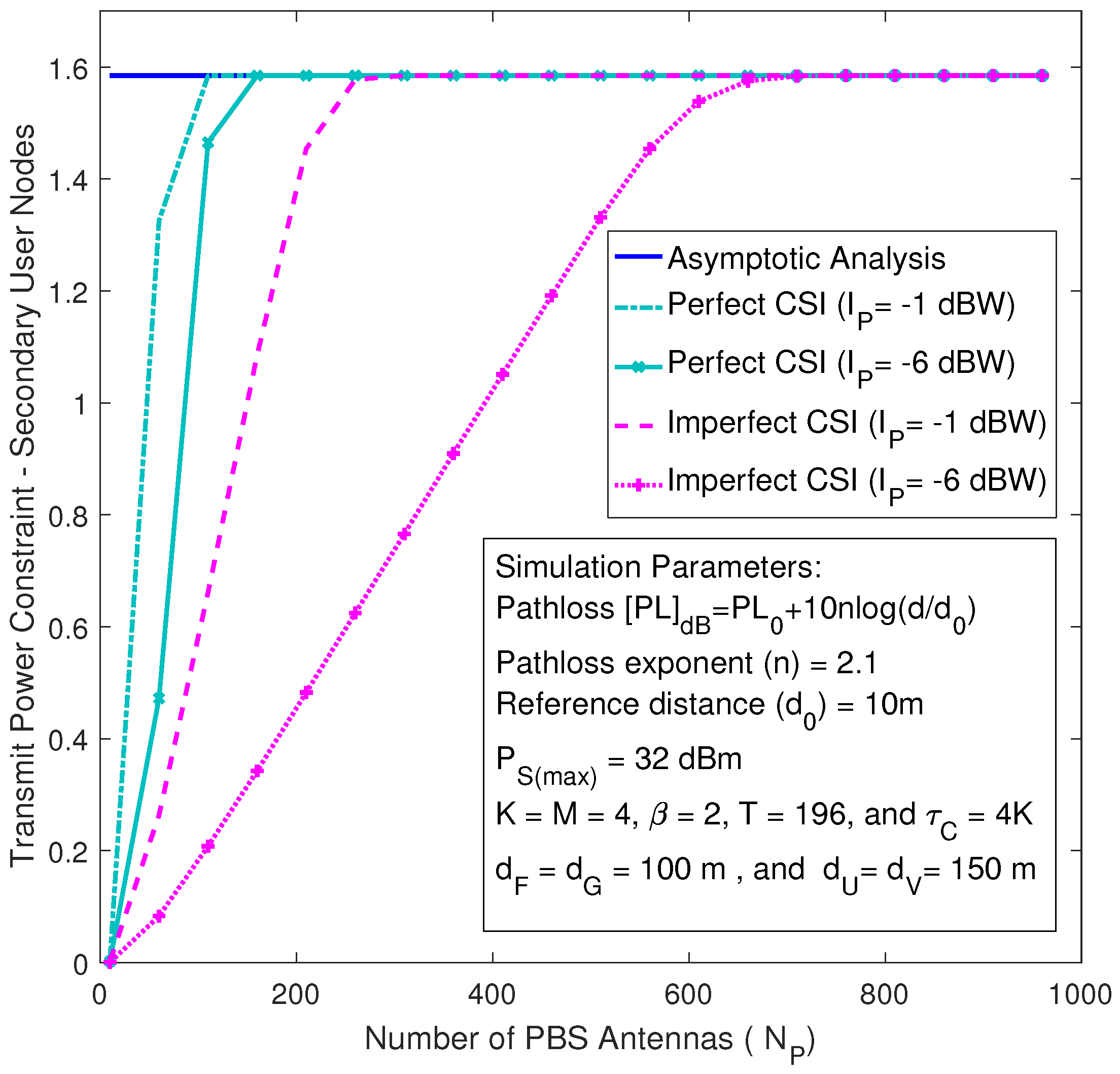
Figure 4.
The transmit power constraint of the secondary system versus the number of PBS antennas by varying M.
Figure 4.
The transmit power constraint of the secondary system versus the number of PBS antennas by varying M.
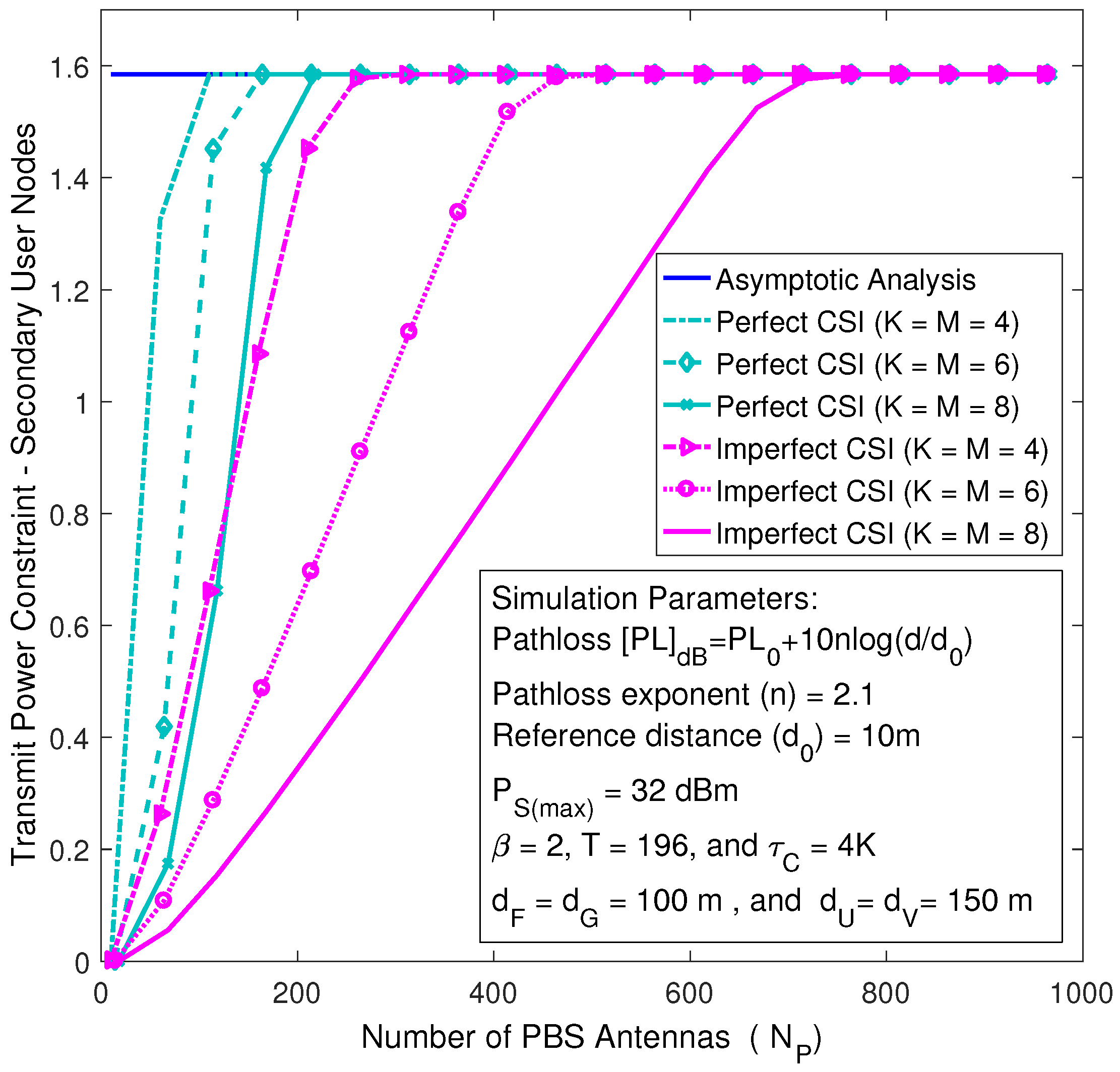
Figure 5.
The achievable secrecy rates versus the number of PBS antennas for perfect CSI case.

© 2017 by the authors. Licensee MDPI, Basel, Switzerland. This article is an open access article distributed under the terms and conditions of the Creative Commons Attribution (CC BY) license (http://creativecommons.org/licenses/by/4.0/).
Share and Cite
MDPI and ACS Style
Al-Hraishawi, H.; Baduge, G.A.A.; Schaefer, R.F. Artificial Noise-Aided Physical Layer Security in Underlay Cognitive Massive MIMO Systems with Pilot Contamination. Entropy 2017, 19, 349. https://doi.org/10.3390/e19070349
AMA Style
Al-Hraishawi H, Baduge GAA, Schaefer RF. Artificial Noise-Aided Physical Layer Security in Underlay Cognitive Massive MIMO Systems with Pilot Contamination. Entropy. 2017; 19(7):349. https://doi.org/10.3390/e19070349
Chicago/Turabian StyleAl-Hraishawi, Hayder, Gayan Amarasuriya Aruma Baduge, and Rafael F. Schaefer. 2017. "Artificial Noise-Aided Physical Layer Security in Underlay Cognitive Massive MIMO Systems with Pilot Contamination" Entropy 19, no. 7: 349. https://doi.org/10.3390/e19070349
Note that from the first issue of 2016, this journal uses article numbers instead of page numbers. See further details here.