
Innovative Formulation Combining Al, Zr and Si Precursors to Obtain Anticorrosion Hybrid Sol-Gel Coating

 ,
,
Abstract
:1. Introduction
2. Results and Discussion
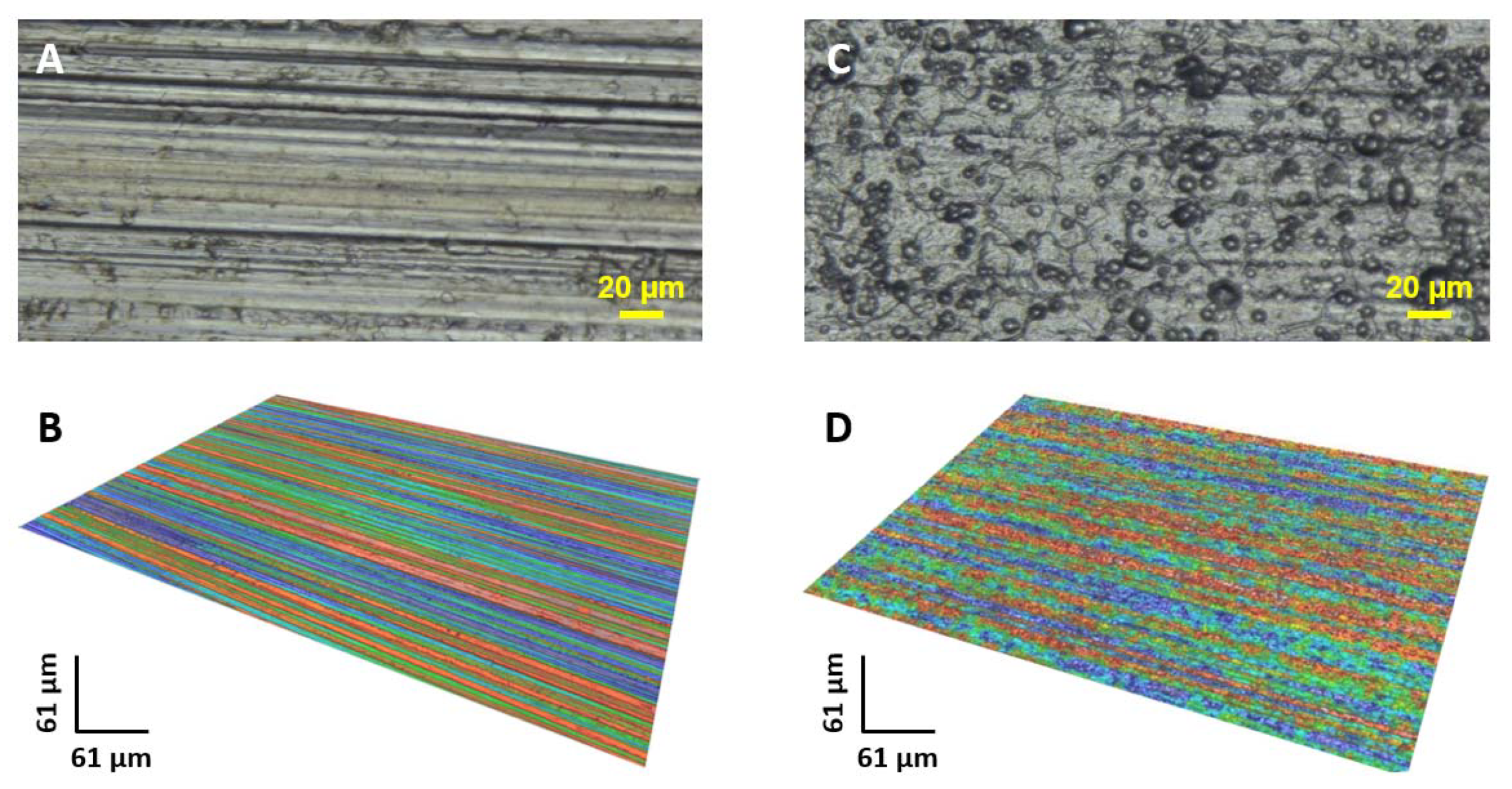
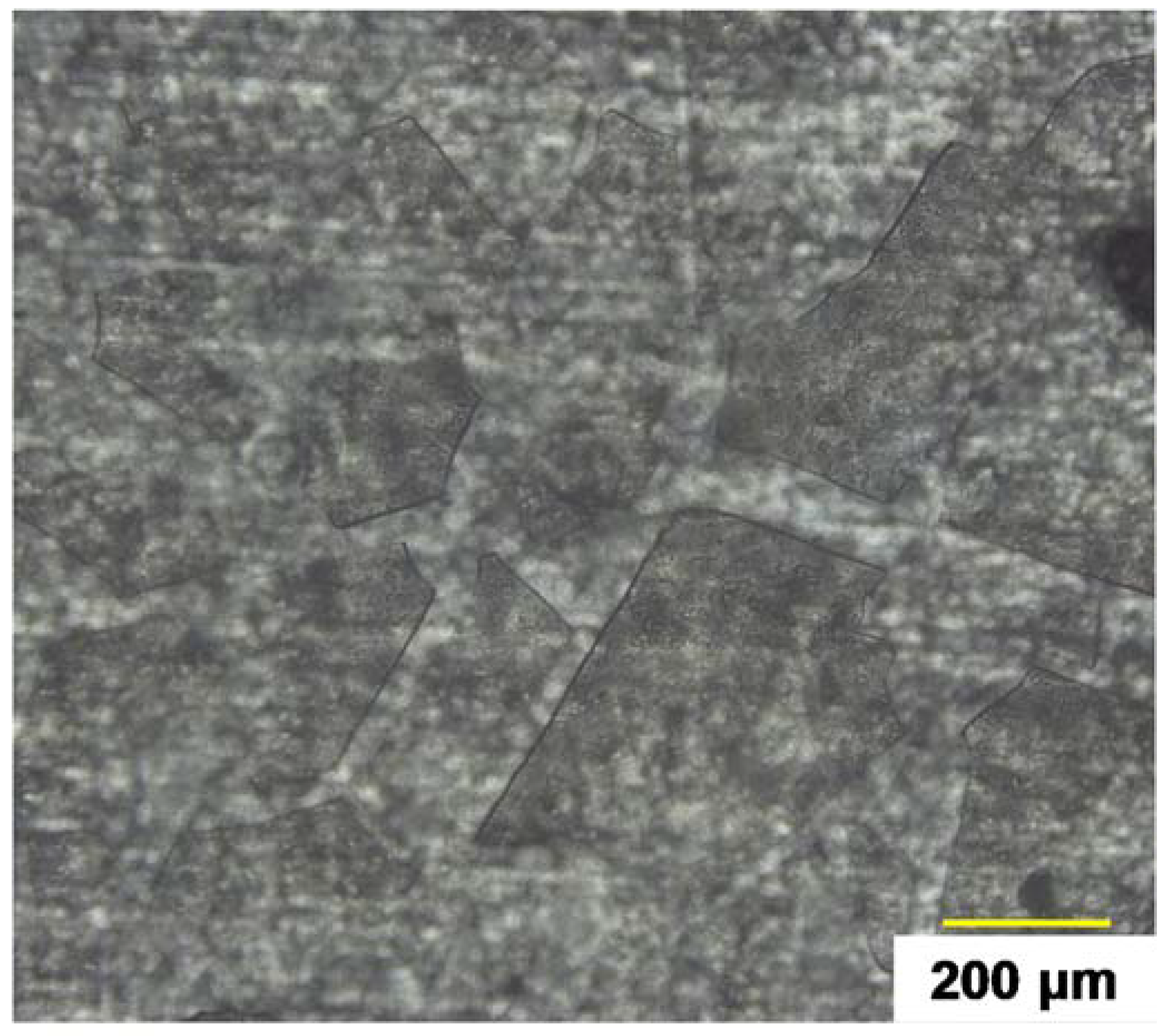
2.1. AA6061 Substrate Characterization
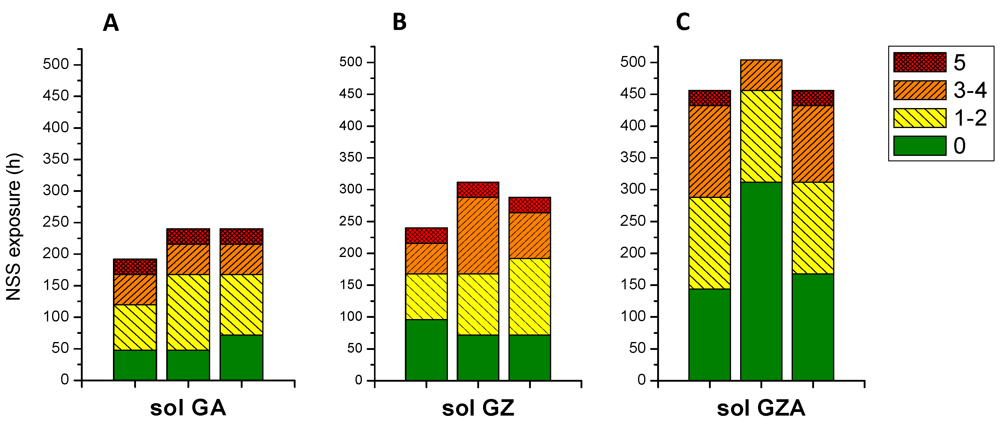
2.2. NSS Tests of Coatings Obtained from GA, GZ and GZA Sols
2.3. Optimization of the Coating from Sol GZA
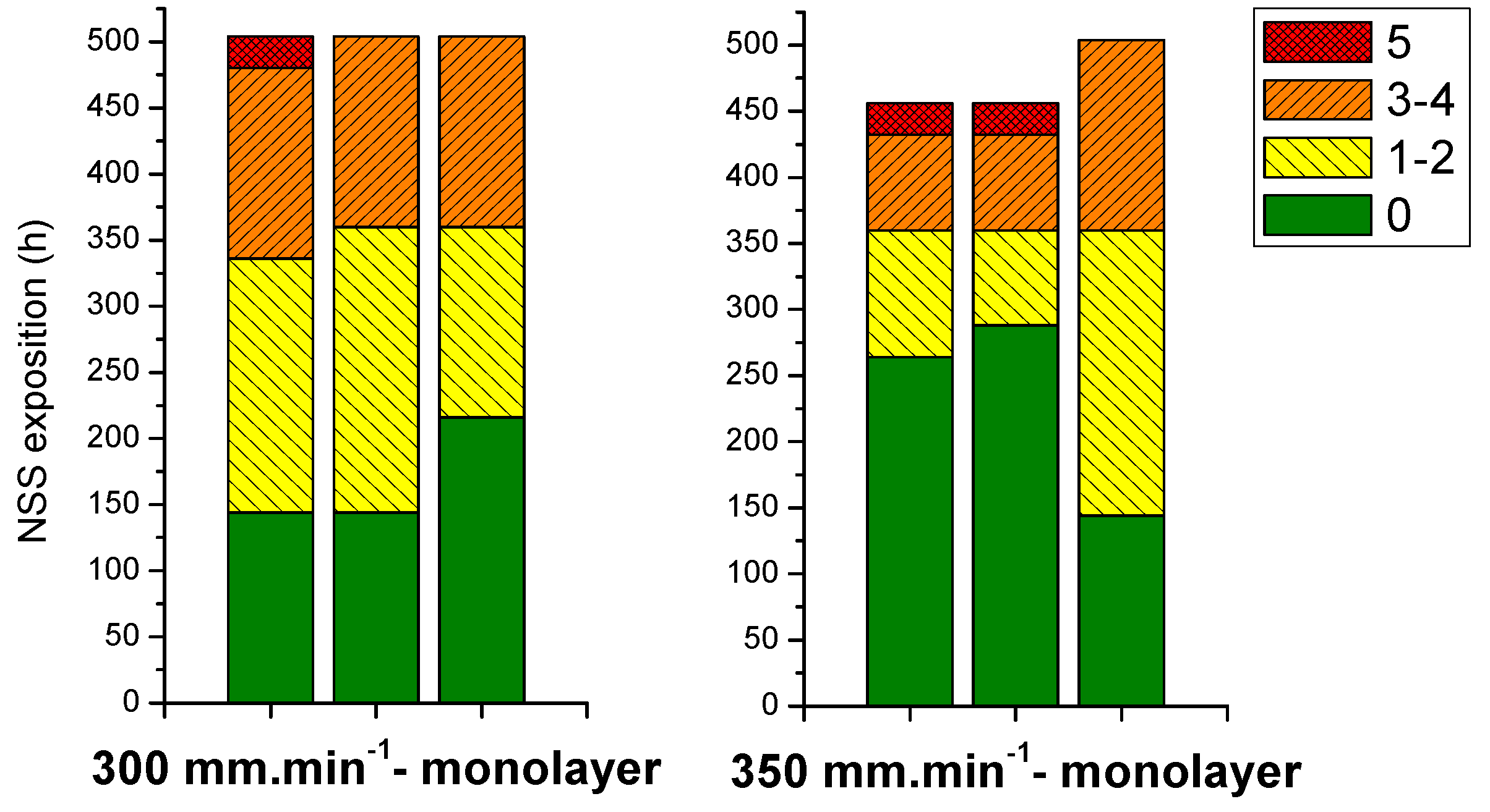
2.3.1. Monolayer Systems
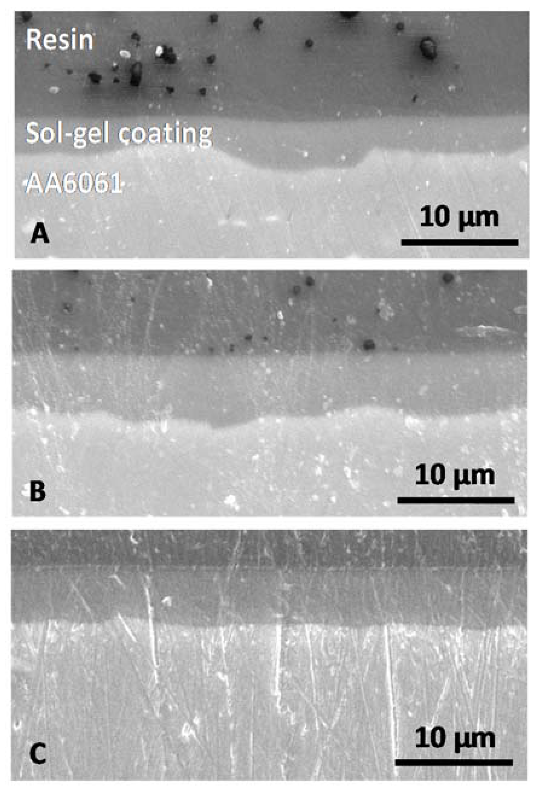
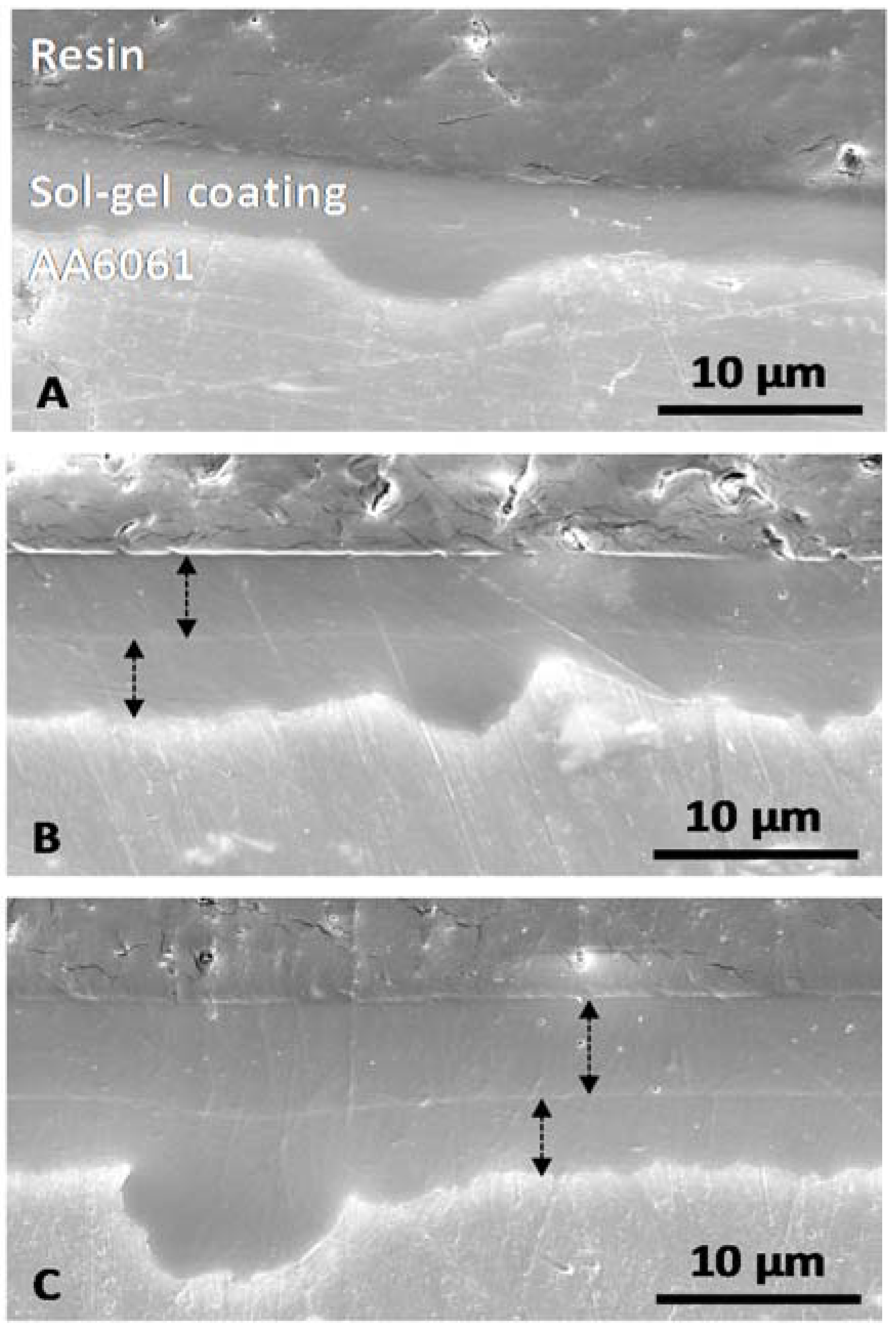
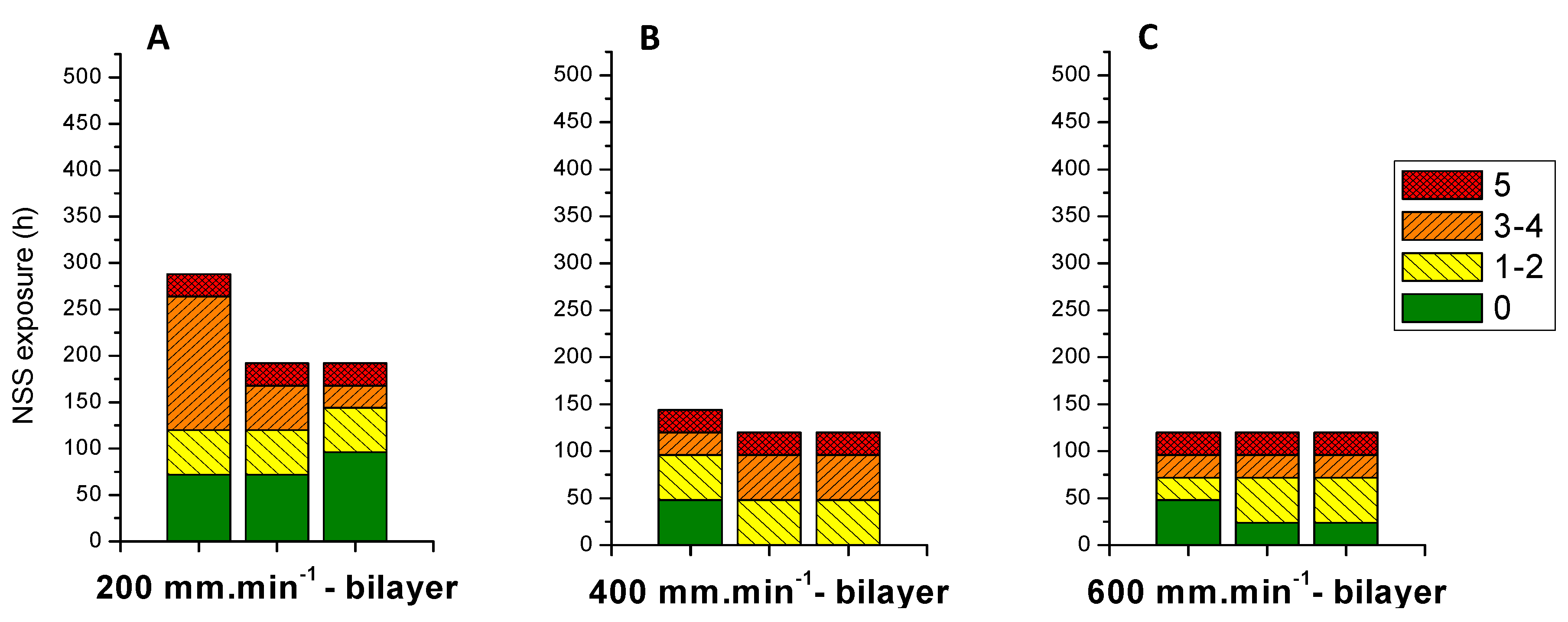
2.3.2. Bilayer Systems
- -
- A weakening can be generated because of the interface due to the double deposition.
- -
- A critical thickness seems to appear without anti-corrosion properties degradation.
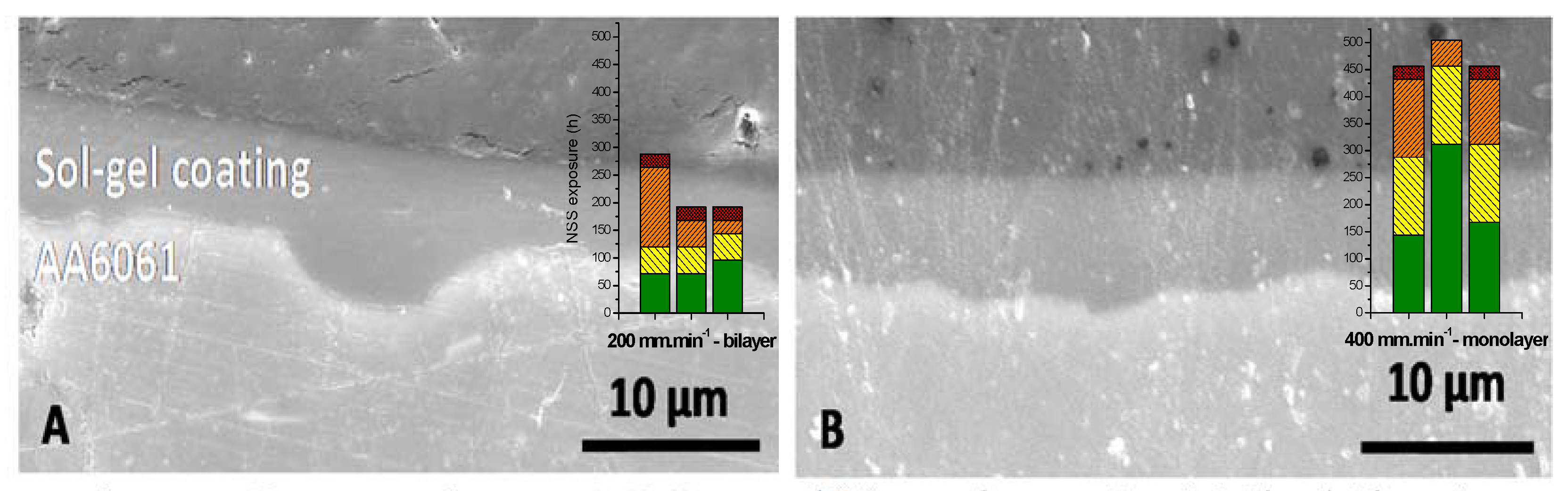
2.3.3. Comparison between Mono and Bilayer System at the Same Thickness
2.3.4. Critical Thickness Identification
3. Experimental
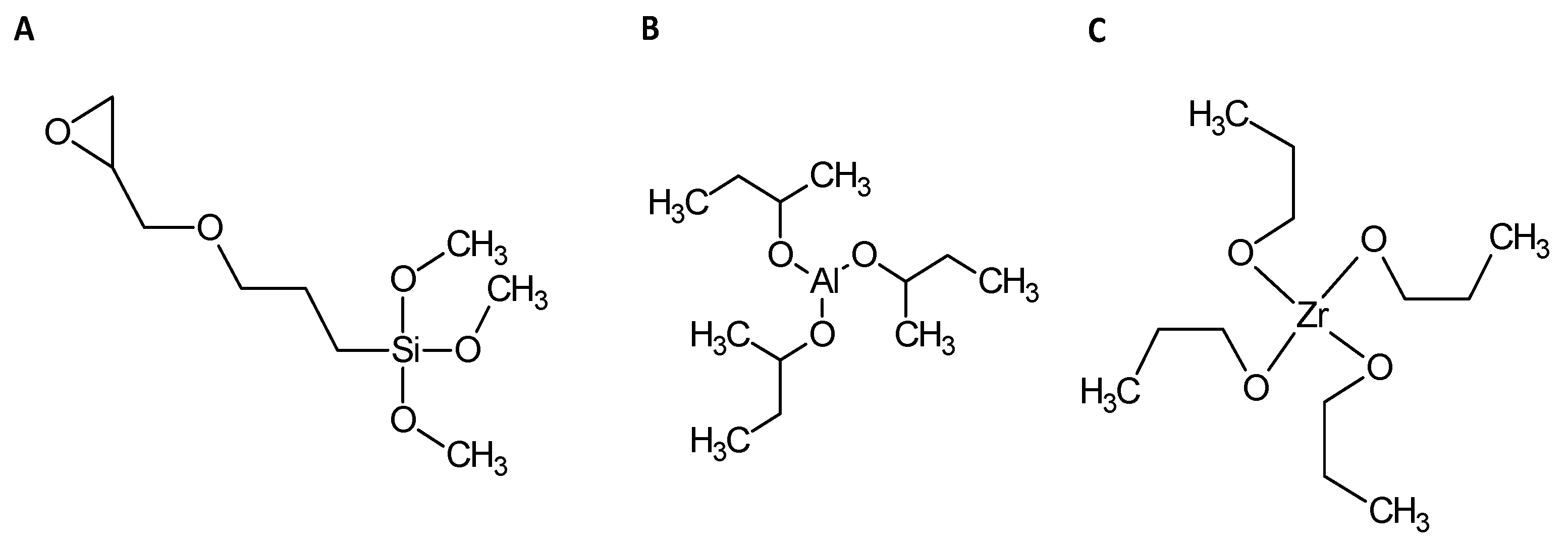
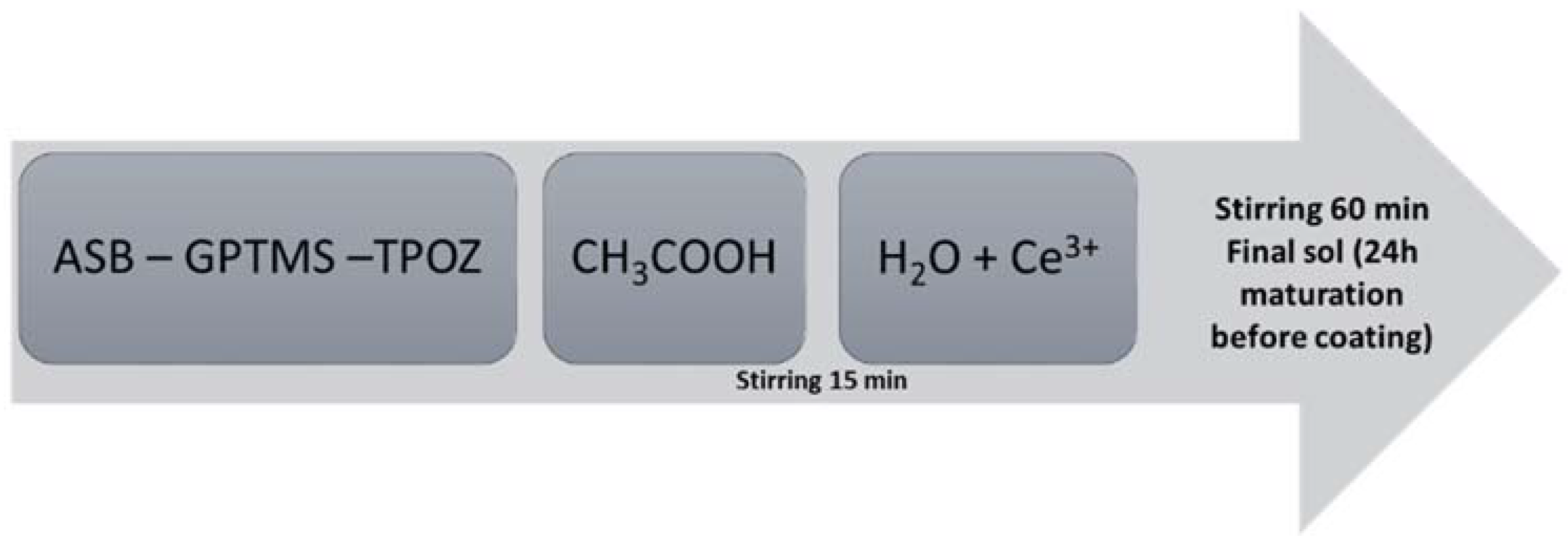
3.1. Materials, Sol Composition and Sol-Gel Synthesis
3.2. Characterization Techniques
3.2.1. Natural Salt Spray Test (NSS)
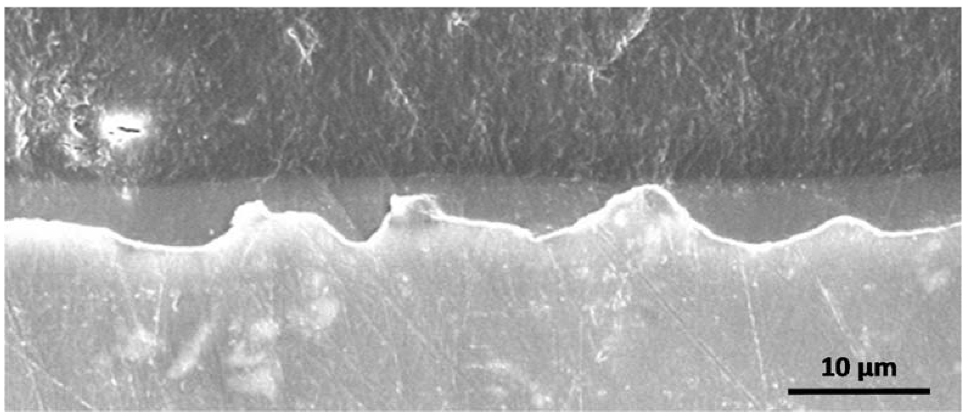
3.2.2. Morphological and Surface Characterizations
3.2.3. Hydrophobicity by Angle Contact Measurement
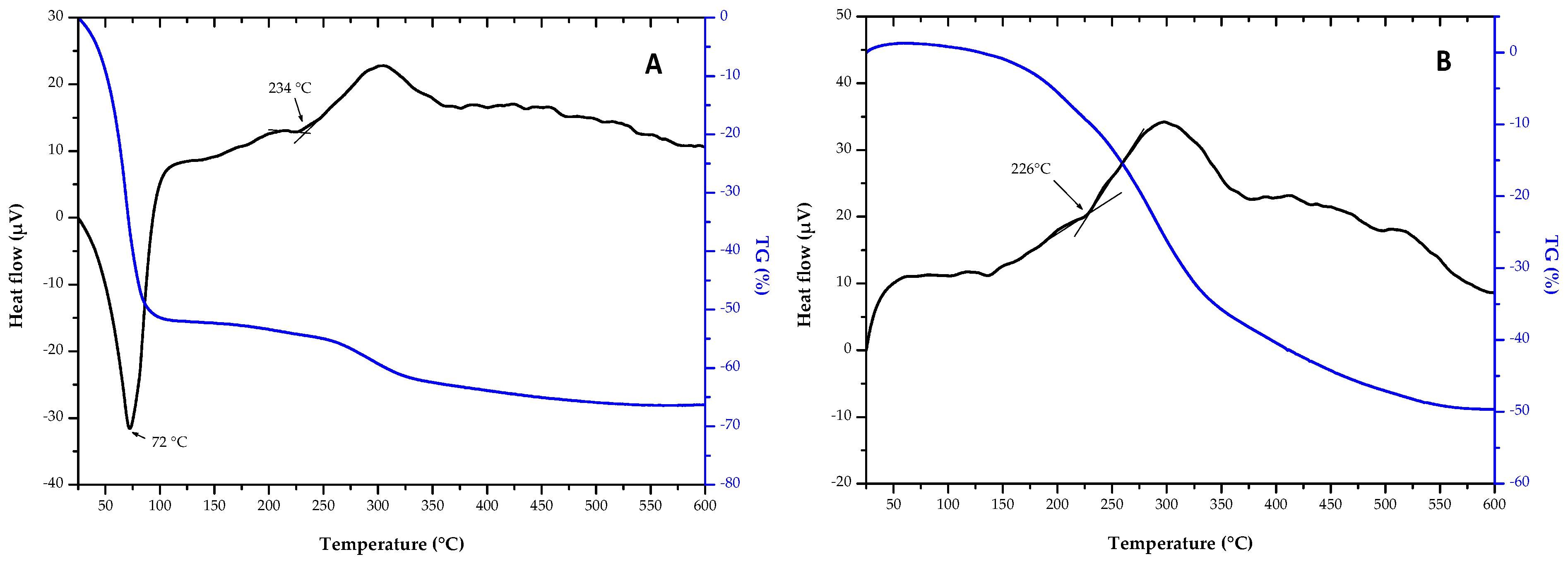
3.2.4. Thermal Analyses (TG-DTA)
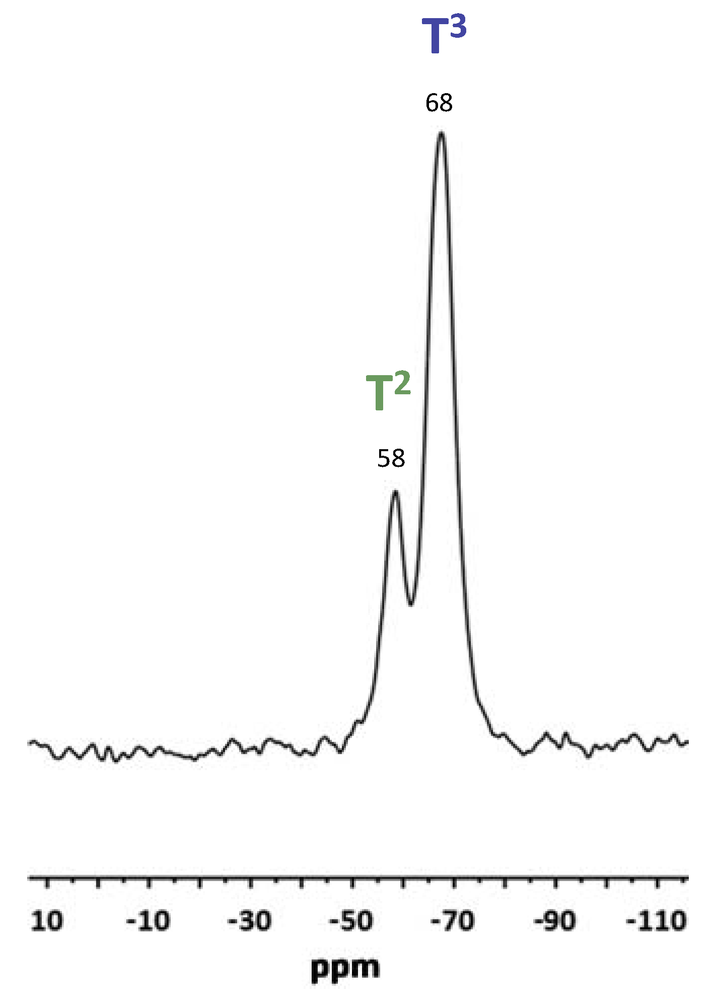
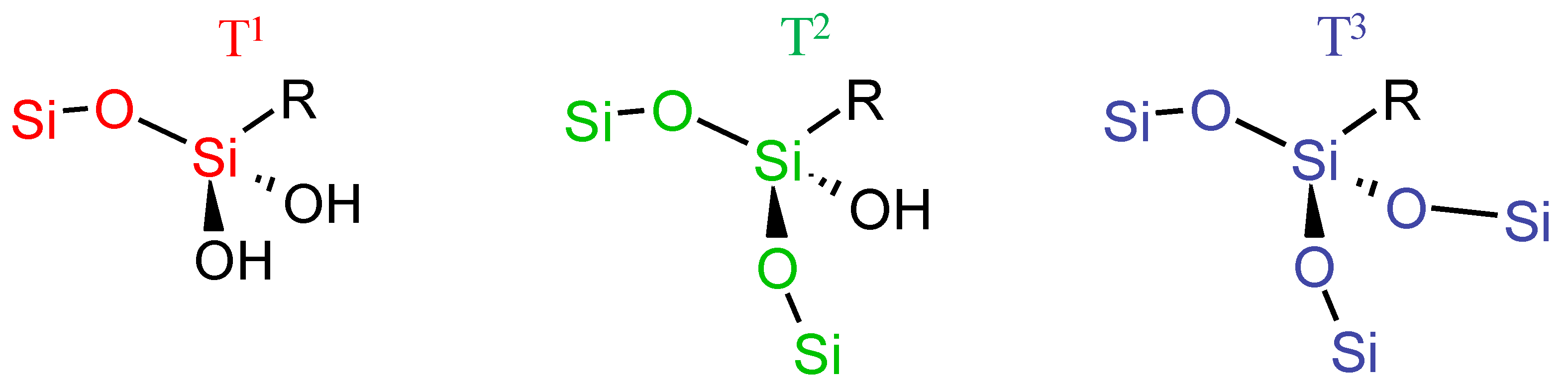
3.2.5. Nuclear Magnetic Resonance (NMR)
4. Conclusions
Author Contributions
Acknowledgments
Conflicts of Interest
References
- Starke, E.A.; Staley, J.T. Application of modern aluminum alloys to aircraft. Prog. Aerosp. Sci. 1996, 32, 131–172. [Google Scholar] [CrossRef]
- Immarigeon, J.P.; Holt, R.T.; Koul, A.K.; Zhao, L.; Wallace, W.; Beddoes, J.C. Lightweight materials for aircraft applications. Mater. Charact. 1995, 35, 41–67. [Google Scholar] [CrossRef]
- Vargel, C.; Jacques, M.; Schmidt, M.P. Corrosion of Aluminium; Elsevier: New York, NY, USA, 2004; ISBN 0080436374. [Google Scholar]
- ECHA European Chemicals Agency. Liste d’autorisations—List of Substances Included in Annex XIV of REACH (“Authorisation List”). Available online: https://echa.europa.eu/fr/authorisation-list (accessed on 24 April 2018).
- Directive 2011/65/UE du Parlement Européen et du Conseil. EUR-Lex. Available online: https://eur-lex.europa.eu/legal-content/FR/TXT/?uri=CELEX:32011L0065 (accessed on 24 April 2018).
- Twite, R.L.; Bierwagen, G.P. Review of alternatives to chromate for corrosion protection of aluminum aerospace alloys. Prog. Org. Coat. 1998, 33, 91–100. [Google Scholar] [CrossRef]
- Chen, W.K.; Lee, J.L.; Bai, C.Y.; Hou, K.H.; Ger, M. Der Growth and characteristics of Cr(III)-based conversion coating on aluminum alloy. J. Taiwan Inst. Chem. Eng. 2012, 43, 989–995. [Google Scholar] [CrossRef]
- Jin, W.; Du, H.; Zheng, S.; Zhang, Y. Electrochemical processes for the environmental remediation of toxic Cr(VI): A review. Electrochim. Acta 2015, 191, 1044–1055. [Google Scholar] [CrossRef]
- Brinker, C.J.; Hurd, A.J.; Schunk, P.R.; Frye, G.C.; Ashley, C.S. Review of sol-gel thin film formation. J. Non Cryst. Solids 1992, 147–148, 424–436. [Google Scholar] [CrossRef]
- Wang, D.; Bierwagen, G.P. Sol-gel coatings on metals for corrosion protection. Prog. Org. Coat. 2009, 64, 327–338. [Google Scholar] [CrossRef]
- Zheludkevich, M.L.; Tedim, J.; Ferreira, M.G.S. “Smart” coatings for active corrosion protection based on multi-functional micro and nanocontainers. Electrochim. Acta 2012, 82, 314–323. [Google Scholar] [CrossRef]
- Figueira, R.B.; Silva, C.J.R.; Pereira, E.V. Organic–inorganic hybrid sol–gel coatings for metal corrosion protection: A review of recent progress. J. Coat. Technol. Res. 2015, 12, 1–35. [Google Scholar] [CrossRef]
- Mackenzie, J.D.; Bescher, E.P. Mechanical Properties of Organic–Inorganic Hybrids. In Handbook of Sol-gel Science and Technology. 2. Characterization and Properties of Sol-Gel Materials and Products; Springer Science & Business Media: Berlin, Germany, 2005; Volume 2, p. 313. [Google Scholar]
- Cambon, J.-B.; Esteban, J.; Ansart, F.; Bonino, J.-P.; Turq, V.; Santagneli, S.H.; Santalli, C.V.; Pulcinelli, S.H. Effect of cerium on structure modifictions of a hybrid sol-gel coating, its mechanical properties and anti-corrorion behaviour. Mater. Res. Bull. 2012, 47, 3170–3176. [Google Scholar] [CrossRef] [Green Version]
- Zheludkevich, M.L.; Serra, R.; Montemor, M.F.; Miranda Salvado, I.M.; Ferreira, M.G.S. Corrosion protective properties of nanostructured sol-gel hybrid coatings to AA2024-T3. Surf. Coat. Technol. 2006, 200, 3084–3094. [Google Scholar] [CrossRef]
- Fu, C.J.; Zhan, Z.W.; Yu, M.; Li, S.M.; Liu, J.H.; Dong, L. Influence of Zr/Si Molar Ratio on Structure, Morphology and Corrosion Resistance of Organosilane Coatings Doped with Zirconium ( IV ) n-propoxide. Int. J. Electrochem. Sci. 2014, 9, 2603–2619. [Google Scholar]
- Bahrami, M.; Borhani, G.H.; Bakhshi, S.R.; Ghasemi, A. Optimization of effective processing parameters of hybrid anti-corrosion Si/Zr sol-gel coatings doped with cerium salt for aluminum alloy 6061. J. Sol-Gel Sci. Technol. 2017, 81, 921–933. [Google Scholar] [CrossRef]
- Rodič, P.; Mertelj, A.; Borovšak, M.; Benčan, A.; Mihailović, D.; Malič, B.; Milošev, I. Composition, structure and morphology of hybrid acrylate-based sol–gel coatings containing Si and Zr composed for protective applications. Surf. Coat. Technol. 2016, 286, 388–396. [Google Scholar] [CrossRef]
- Cullen, M.; Morshed, M.; Sullivan, M.O.; Machugh, E.; Duffy, B.; Oubaha, M. Correlation between the structure and the anticorrosion barrier properties of hybrid sol–gel coatings: Application to the protection of AA2024-T3 alloys. J. Sol-Gel Sci. Technol. 2017, 82, 801–806. [Google Scholar] [CrossRef]
- Balaskas, A.C.; Kartsonakis, I.A.; Snihirova, D.; Montemor, M.F.; Kordas, G. Improving the corrosion protection properties of organically modified silicate-epoxy coatings by incorporation of organic and inorganic inhibitors. Prog. Org. Coat. 2011, 72, 653–662. [Google Scholar] [CrossRef]
- Zheludkevich, M.L.; Serra, R.; Montemor, M.F.; Yasakau, K.A.; Salvado, I.M.M.; Ferreira, M.G.S. Nanostructured sol-gel coatings doped with cerium nitrate as pre-treatments for AA2024-T3 Corrosion protection performance. Electrochim. Acta 2005, 51, 208–217. [Google Scholar] [CrossRef]
- Yasakau, K.A.; Zheludkevich, M.L.; Karavai, O.V.; Ferreira, M.G.S. Influence of inhibitor addition on the corrosion protection performance of sol-gel coatings on AA2024. Prog. Org. Coat. 2008, 63, 352–361. [Google Scholar] [CrossRef]
- Yasakau, K.A.; Carneiro, J.; Zheludkevich, M.L.; Ferreira, M.G.S. Influence of sol-gel process parameters on the protection properties of sol-gel coatings applied on AA2024. Surf. Coat. Technol. 2014, 246, 6–16. [Google Scholar] [CrossRef]
- Brinker, C.J.; Frye, G.C.; Hurd, A.J.; Ashley, C.S. Fundamentals of sol-gel dip coating. Thin Solid Films 1991, 201, 97–108. [Google Scholar] [CrossRef]
- O’Sullivan, M.; Odewunmi, N.A.; Cullen, M.; Sorour, A.A.; Duffy, B.; Gasem, Z.M.; Oubaha, M. The Role of the Chelating Agent on the Structure and Anticorrosion Performances of an Organosilane—Zirconium Sol-Gel Coatings. Adv. Mater. Phys. Chem. 2018, 8, 89–104. [Google Scholar] [CrossRef]
- Schmidt, H.; Seiferling, B. Chemistry and application of inorganic–organic polymers: Organically modified silicates. Mater. Res. Soc. Symp. Proc. 1986, 73, 744. [Google Scholar] [CrossRef]
- Massiot, D.; Fayon, F.; Capron, M.; King, I.; Le Calvé, S.; Alonso, B.; Durand, J.O.; Bujoli, B.; Gan, Z.; Hoatson, G. Modelling one- and two-dimensional solid-state NMR spectra. Magn. Reson. Chem. 2002, 40, 70–76. [Google Scholar] [CrossRef]
- Landau, L.; Levich, B. Dragging of a Liquid by a Moving Plate. Dyn. Curved Front. 1988, 141–153. [Google Scholar] [CrossRef]
Sample Availability: Samples of the compounds are not available from the authors. |


| Ratio | T1 | T2 | T3 | τ (%) |
|---|---|---|---|---|
| GZA | 0 | 0.23 | 0.77 | 92.3 |
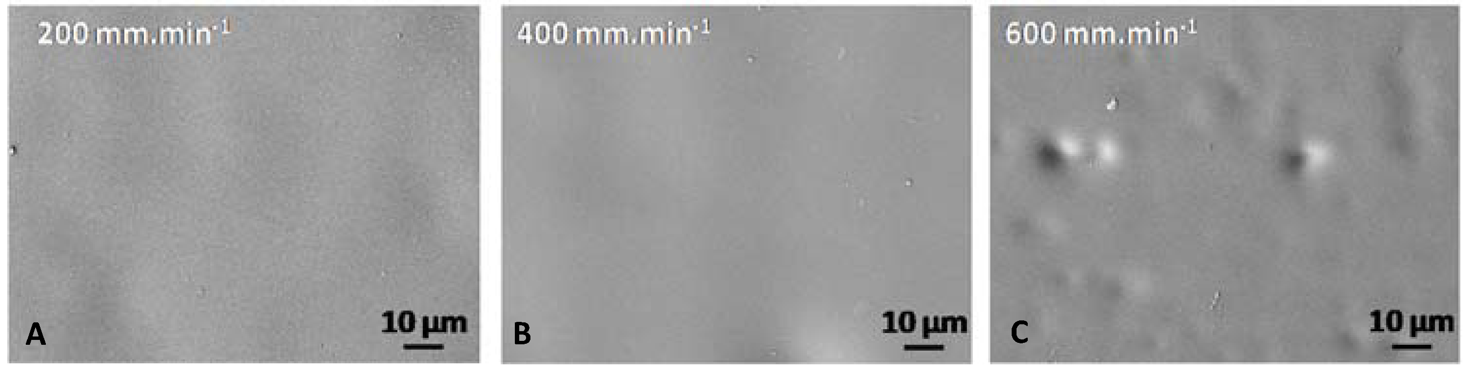
| Withdrawal Speed (mm·min−1) | 200 | 400 | 600 |
| Thickness (µm) | 2.7 | 5.0 | 5.8 |
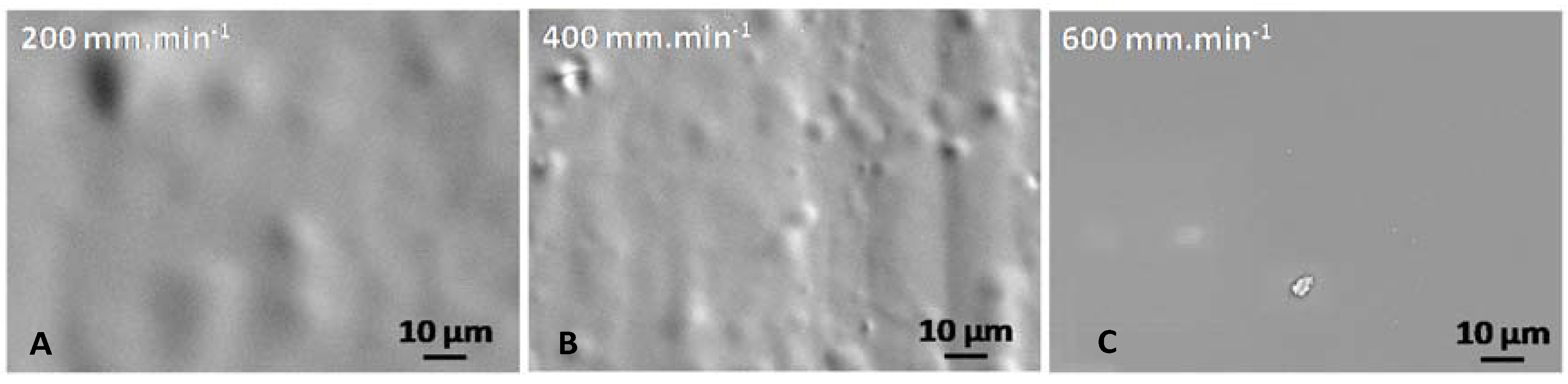
| Withdrawal Speed (mm·min−1) | 200 | 400 | 600 |
| Thickness (µm) | 5.3 | 8.2 | 9.5 |
| Element | Al | Mg | Si | Fe | Cu | Zn | Mn | Cr | Ti |
|---|---|---|---|---|---|---|---|---|---|
| Wt % | balance | 0.8–1.2 | 0.4–0.8 | 0.7 | 0.15–0.4 | 0.25 | 0.15 | 0.04–0.35 | 0.15 |
| Sol Reference | Si/Al | Si/Zr | CH3COOH/Si | CH3COOH/Zr | H |
|---|---|---|---|---|---|
| GZ | / | 2 | / | 4 | 4 |
| GA | 4 | / | 1 | / | 4 |
| GZA | 4 | 2 | / | 4 | 4.35 |
© 2018 by the authors. Licensee MDPI, Basel, Switzerland. This article is an open access article distributed under the terms and conditions of the Creative Commons Attribution (CC BY) license (http://creativecommons.org/licenses/by/4.0/).
Share and Cite
Genet, C.; Menu, M.-J.; Gavard, O.; Ansart, F.; Gressier, M.; Montpellaz, R. Innovative Formulation Combining Al, Zr and Si Precursors to Obtain Anticorrosion Hybrid Sol-Gel Coating. Molecules 2018, 23, 1135. https://doi.org/10.3390/molecules23051135
Genet C, Menu M-J, Gavard O, Ansart F, Gressier M, Montpellaz R. Innovative Formulation Combining Al, Zr and Si Precursors to Obtain Anticorrosion Hybrid Sol-Gel Coating. Molecules. 2018; 23(5):1135. https://doi.org/10.3390/molecules23051135
Chicago/Turabian StyleGenet, Clément, Marie-Joëlle Menu, Olivier Gavard, Florence Ansart, Marie Gressier, and Robin Montpellaz. 2018. "Innovative Formulation Combining Al, Zr and Si Precursors to Obtain Anticorrosion Hybrid Sol-Gel Coating" Molecules 23, no. 5: 1135. https://doi.org/10.3390/molecules23051135