Molecular Dynamics Simulations of Nanochannel Flows at Low Reynolds Numbers

Department of Mechanical Engineering, The University of Hong Kong, Pokfulam Road, Hong Kong
*
Author to whom correspondence should be addressed.
Molecules 2003, 8(1), 193-206; https://doi.org/10.3390/80100193
Submission received: 1 January 2003
/
Published: 31 January 2003
(This article belongs to the Special Issue Selected Papers from the International Symposium on Frontiers in Molecular Science (ISFMS 2002))
Abstract
:In this paper we use molecular dynamics (MD) simulations to study nano- channel flows at low Reynolds numbers and present some new interesting results. We investigated a simple fluid flowing through channels of different shapes at the nano level. The Weeks-Chandler-Anderson potentials with different interaction strength factors are adopted for the interaction forces between fluid-fluid and fluid-wall molecules. In order to keep the temperature at the required level, a Gaussian thermostat is employed in our MD simulations. Comparing velocities and other flow parameters obtained from the MD simulations with those predicted by the classical Navier-Stokes equations at same Reynolds numbers, we find that both results agree with each other qualitatively in the central area of a nanochannel. However, large deviation usually exists in areas far from the core. For certain complex nanochannel flow geometry, the MD simulations reveal the generation and development of nano-size vortices due to the large momenta of molecules in the near-wall region while the traditional Navier-Stokes equations with the non-slip boundary condition at low Reynolds numbers cannot predict the similar phenomena. It is shown that although the Navier-Stokes equations are still partially valid, they fail to give whole details for nanochannel flows.
I. INTRODUCTION
The behavior of a flow at the nanometer scale has been a subject of interest in recent years. As a typical flow in the reduced-size fluid mechanics system, the nanochannel flow embodies a series of special properties and has attracted much attention. The understanding of the physical properties and dynamical behavior of nanochannel flows has great importance on the theoretical study of fluid dynamics and many engineering applications in physics, chemistry, medicine and electronics.
It is obvious that when the system length reduces to the nano scale, the behavior of the flow is mainly affected by the movements and structure of many discrete particles. The molecular dynamics (MD) simulation, based on the statistical mechanics of nonequilibrium liquids [1], is an effective way to describe the details of a flow at the nano scale. At the same time, MD simulations also calculate physical properties of nanofluids by solving the equations of molecular motion. The role of replacing the continuum description for the nano level flows makes MD a powerful tool to study many fundamental nanofluid problems which may be extremely difficult to be implemented in the laboratory at the present time. MD simulation has been used successfully in studying aspects of molecular hydrodynamics, such as the lubrication, wetting and coating problems. Simple or complex channel flows have been investigated by several researchers, e.g. Todd et al. [2] and Jabbarzadeh et al. [3].
Couette and Poiseuille flows of simple Lennard-Jones liquids or polymers in a nanochannel of several molecular sizes demonstrate some new features and have also attracted much attention at the present. The salient features of such simple flows are the departure from the Navier-Stokes (NS) theory [4] and some different dynamic properties compared with the macroscopic systems [5]. It is well known that the quadratic velocity profile in a Poiseuille flow may be successfully predicted in the Newtonian fluid mechanics framework when the fluid density is assumed to be a temperature dependent function and does not vary appreciably over the length and time scale comparable to the molecular size and molecular relaxation time. The transport coefficients are also considered to be space and time independent in the classical continuum theory. However, as we focus attention on flows at nano level, the density becomes a function related to the position and time of fluid particles, that means, the density cannot be uniform in space and time. The irregular density distribution also affects other physical properties and hence changes the dynamical behavior of a nanofluid system. Travis and Gubbins [6] reported that the density oscillates along the flow direction with a wavelength of the order of a molecular diameter in a channel of about 4 molecular-diameter width. They also verified that the quadratic velocity profile is approximately obtained for a channel of 10 molecular-diameter width in a planar Poiseuille flow, but this phenomenon disappears when the channel width is less than 10 molecular diameters. They even indicated that the disagreement with the NS prediction occurs when the channel width is of the order of 5 molecular diameters. Koplik and Banavar [7] further pointed out that the classical fluid mechanics theory can be applied safely for Couette and Poiseuille flows in channels of width greater than 10 molecular diameters with no-slip boundary conditions. Based on such assumptions, Fan et al. [5] carried out simulations of a periodic nozzle flow of a Weeks-Chandler-Anderson (WCA) liquid.
The flow that occurs in a practical nanochannel may be more complicated than a simple Poiseuille flow in that many factors such as the channel geometry, flow type and boundary conditions may be involved altogether. The faced challenge in this area is to find the deviation between the MD simulation and the classical NS prediction, and to obtain the qualitative difference between them with physical explanation. In this paper, we will focus mainly on flows of a simple liquid in various channels. We employ the MD simulations to explore the dynamic details of nanochannel flows and try to examine the limitations of the NS solutions for a liquid moving along nanochannels.
II. PHYSICAL MODELS
In this paper, we assume the liquids are constituted of quantities of spherical molecules. As a rigorous quantum-mechanical approach is not feasible at the present for a system of more than a few molecules, Newton’s second law is regarded as valid to describe the molecular motion in the system. For a fluid, the momentum pi of molecule i should satisfy Newton’s second law
where Fi is the intermolecular force on molecule i by other molecules, and Fe is the external force. In simulation, the external force may be the body force, e.g. the gravity force. The velocity vi of molecule i is related to the fluid molecule mass m By
The molecular interaction forces usually depend on the physical properties and space phase structures of the fluid and wall molecules. A complex model taking into account both the fluid/fluid and fluid/wall intermolecular interactions is presented in this paper to obtain the velocity and stress distributions in a nanochannel flow. For the fluid/fluid interaction, both repulsion and dispersion effects of molecules are considered. The WCA potential, which is a modification of the Lennard-Jones potential, is adopted in the MD simulations in this paper
where σ is the diameter of a molecule, ε is the energy parameter characterizing the molecular interaction strength and rc stands for the cutoff distance. For the fluid/wall interaction, noting the existence of the fluid-solid melting line and probable substance interchange on the boundary, a realistic sixth-power soft sphere potential is used to simulate the nanofluid system.
where εfw is called the fluid-wall energy parameter. For the weak fluid-wall interaction, we take εfw = ε, and for the strong fluid-wall interaction, εfw = 3.5ε. The factor 3.5 is obtained by matching the argon potential well on a smooth wall (Heinbuch & Fischer [8]).
In MD simulations, the solid walls may be represented by several layers of wall molecules which are located at the sites of a planar face-centered lattice or a body-centred cubic lattice. Each wall molecule is assumed to be anchored at its lattice site by a stiff spring. A Hookean spring force is introduced here as the external force for wall molecules. For simplicity, we adopt the two-layer linear spring model. The potential may be written as
where δ the displacement of the wall molecule from its lattice site, and C is the stiffness of the spring. To keep the molecular oscillation small from its site and to overcome the slip problem, a relatively soft wall spring with a stiffness of C = 75ε/σ2 is adopted.
From the viewpoint of a microscopic system of particles, the stress tensor is just a result of the space phase distribution and the dynamic properties generated by the movements of molecules in the system. According to the Irving-Kirkwood method [9], the contribution of each particle to the stress tensor may be divided into two parts, a kinetic component related to the velocity distribution and a configuration component related to the position distribution of particles. The stress tensor is written as
The angular brackets denote the ensemble average, n is the density. The first sum on the right-hand side indicates the contribution from the momentum transfer where m is the molecular mass, uα and uβ are the peculiar velocity components of molecule i in the α and β directions. The second sum represents the potential contribution where rα and Fβ are the α and β components of the distance vector and the potential force vector between two molecules. For a simple channel flow, the viscosity of the fluid is calculated by the formula μ = τ/γ, the shear rate γ is usually acquired by the finite difference method.
III. SIMULATION METHOD
We have outlined in the previous section the molecular models to be used in our MD simulations. The simulation details of a liquid flowing through various nanochannels will be given here. For brevity, we use a reduced system to perform the simulations. The units of the characteristic quantities are listed in Table 1 for constructing the dimensionless parameters used in the simulations.

| Characteristic quantity | Unit |
| Mass, m | m |
| Length, l | σ |
| Time, t | σ(m/ε)½ |
| Density, ρ | m / σ3 |
| Velocity, u | (ε / m)½ |
| Shear stress or pressure, τ | ε / σ3 |
| Shear rate, γ | (ε / m)½ / σ |
| Viscosity, μ | (ε·m)½ / σ2 |
| Diffusivity, D | σ(ε / m)½ |
As the work done by the external force may partially be converted into heat in the system, the wall/fluid interaction also contributes to the increase of temperatures of the fluid and the wall. It is important to keep the nano-scale fluid system at a fixed temperature during the simulation. There are usually two ways to keep the temperature of the system constant, using a thermostat or adjusting the temperature by re-scaling the molecular peculiar velocity during the simulation. The latter method requires more calculation work, as the approach is to adjust the wall temperature to a given constant at each time step [8]. It produces satisfactory results in many cases as long as the wall and fluid temperatures link appropriately. As regards to the use of thermostats, some researchers have argued that although it imposes additional constrains on the equations of motion, it improves computation efficiency when applied to a more complex system and sometimes even enhances the accuracy of the simulation [3]. In order to avoid some unphysical effects in the simulation, a Gaussian thermostat method [1], which has been approved to be a good thermostat method, is adopted here to obtain reasonable simulation results. Actually, the Gaussian Method is to add an external force with the following term
where Pi is the peculiar momentum of molecule i and coefficient ξ represents the thermostatting multiplier for keeping the kinetic temperature fixed in the system,
where γi is the local shear rate of flow field at ri and Pix and Piy are the x and y components of the peculiar momentum of molecule i.
Fe = −ξPi
In this simulation, we have developed a FORTRAN code program called MDFluid. MDFluid consists of three modules: data preprocessor, MD simulation and data output. The first part is used to generate the initial configuration of the computation domain. The second part is the core module and its main function is to realize the MD simulation for a nanofluid and to acquire the flow field via some initial and boundary conditions. It is open to adopt different algorithms for the computation of velocity and temperature. The last part is the data output interface. Currently MDFluid is only suitable for several simple nano flows, it is under further development by us. For simplicity, the mass of wall molecules is usually assumed to be identical to that of fluid molecules. The initial configuration of wall molecules are generated separately by the preprocessing module and read in as input data. The total number of molecules depends on the size and geometry of the computational domain and the densities of the fluid and wall materials. All fluid molecules are initially located at the sites of a face-centered lattice. The initial velocities of inner fluid and wall molecules are set randomly according to the given temperature and the inlet and outlet velocities are assigned the same velocity profile due to the periodic boundary condition. At the beginning of simulation, fluid molecules are allowed to move without applying the external force until a thermodynamic equilibrium state is reached. Then the external force field is switched on and the non-equilibrium simulation starts. During the course of simulation, the equations of motion are solved by the leap-frog method. Periodic boundary conditions are applied on the fluid boundary of the computational domain.
To verify and validate the NS equations in a nano scale system is obviously an important and serious task at the present. In this paper, we try to check the validity of the NS equations in a nanochannel flow. Considering a body force exerting on the system, the governing equations in dimensionless form may be written as
where the Reynolds number is defined as Re = ρUL/μ, the fluid density ρ and viscosity μ are assumed to be constants and U and L are the characteristic velocity and length of the domain field. The dimensionless body force is Fbody = ReLg/U2 ex, where g is the gravity constant and ex is the unit vector in the x direction. We use the finite element method (FEM) to obtain the flow field of a nanochannel flow. The same initial and periodic boundary conditions are applied in the FEM simulations. To compare the MD and FEM results, we use the Reynolds number as an adjustable parameter in the FEM to match the flux of the MD simulation. In the framework of continuum fluid mechanics, the Reynolds number plays an important role in analyzing the flow field. Any two solutions with the same Reynolds number and initial/boundary conditions must be similar. In nano flows, the characteristic length reduces to the nano size and the Reynolds number becomes extremely small. In this sense, all nano flows may be classified as low Reynolds number flows and the knowledge on low Reynolds number flows can be inherited in some ways. We wish to find similarities and differences between the NS equations and the MD simulations when they are applied to the same nano fluid system in this paper.
IV. RESULTS AND DISCUSSION
Let us examine five complex channels with different geometry. The first one is a simple plane channel whereas the other four have concave or convex surfaces. The computational domain for the planar flow of a WCA liquid is shown in Figure 1. The system is surrounded by periodic images of itself in x dimension. The computational domain is 0 < x < 200 and -10 < y < 10, the fluid density and viscosity may be determined during simulation.
The periodic dynamic conditions are also used in the course of simulation. The spring constant C of wall molecules is C = 75 and the gravity constant g = 0.5. We assume the fluid/fluid interaction energy parameter ε = 1 and the wall/fluid interaction energy parameter is characterized by εwf = ε or εfw = 3.5ε according to the interaction intensity. For convenience, we compute the five nanochannel flows with the Reynolds number based on the width of the channel being 3 (first three cases) and 5 (last two cases).
Figure 1.
Schematic diagrams of nanochannels with different surfaces
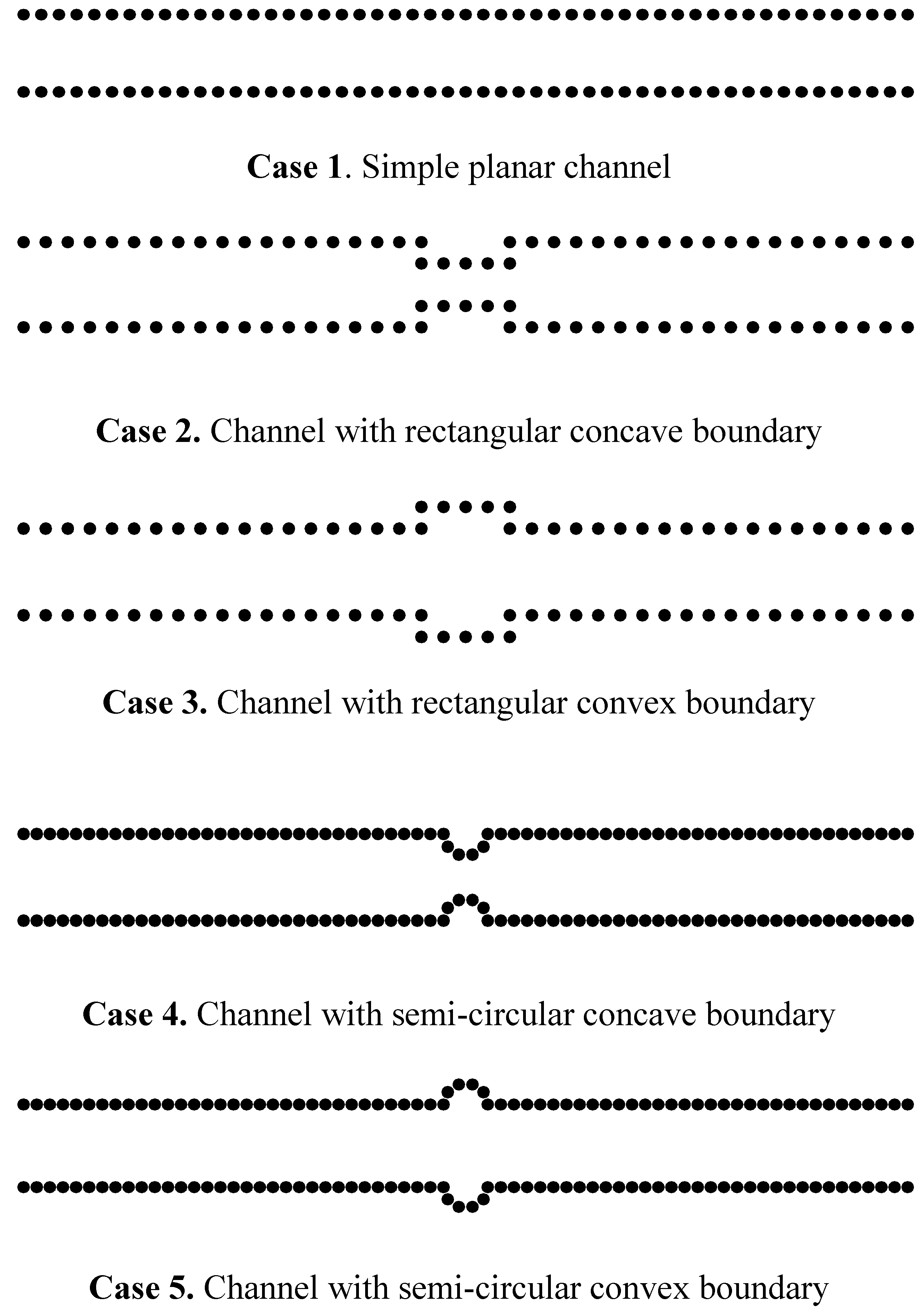
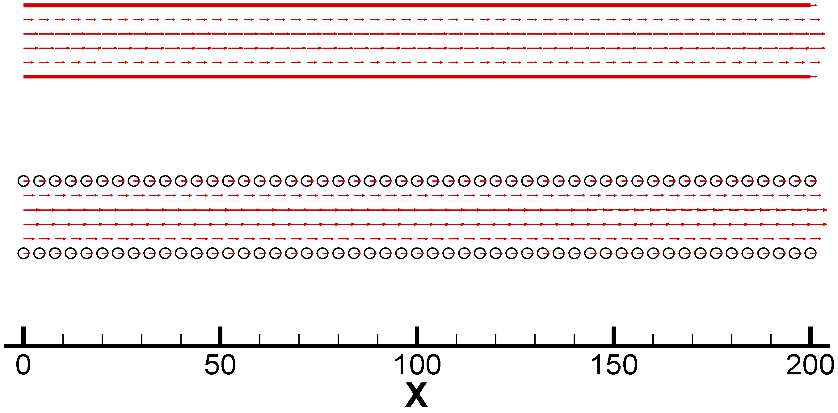
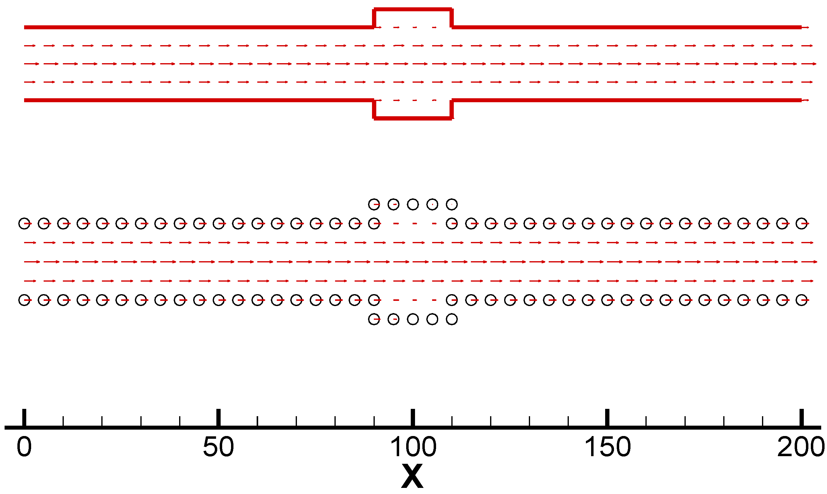
Figure 2 shows the velocity vectors obtained by both the MD simulation and the FEM for the simple planar Poiseuille flow. In the MD simulation, we assume a weak fluid/wall interaction. The channel consists of 1600 fluid molecules bounded by 210 wall molecules which are two layers thick. We find that both flow fields are in qualitative agreement.
Figure 2.
Velocity vectors by the MD simulation (with circle boundary) and the FEM (with solid line boundary) in Case 1
Figure 2.
Velocity vectors by the MD simulation (with circle boundary) and the FEM (with solid line boundary) in Case 1

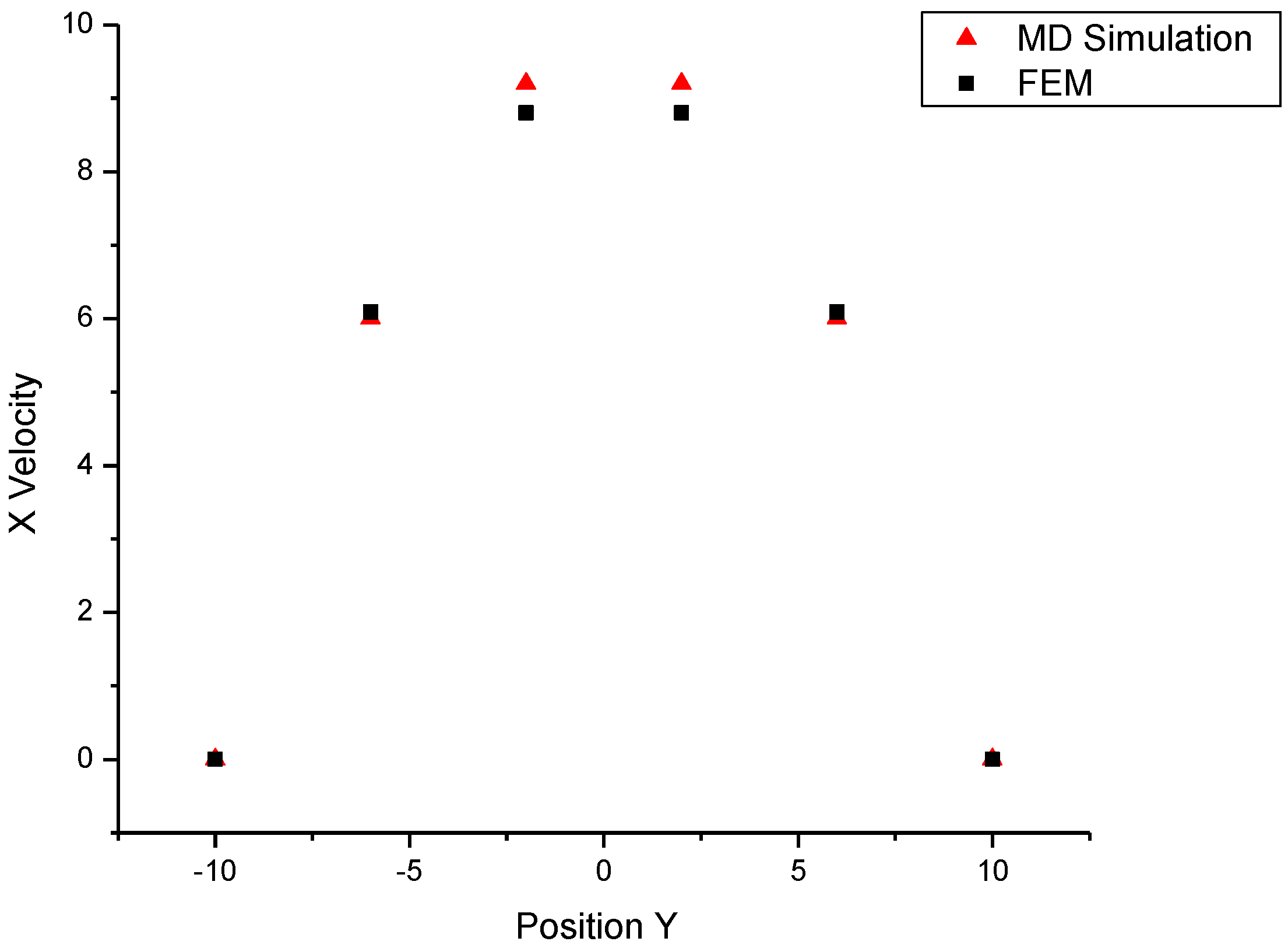
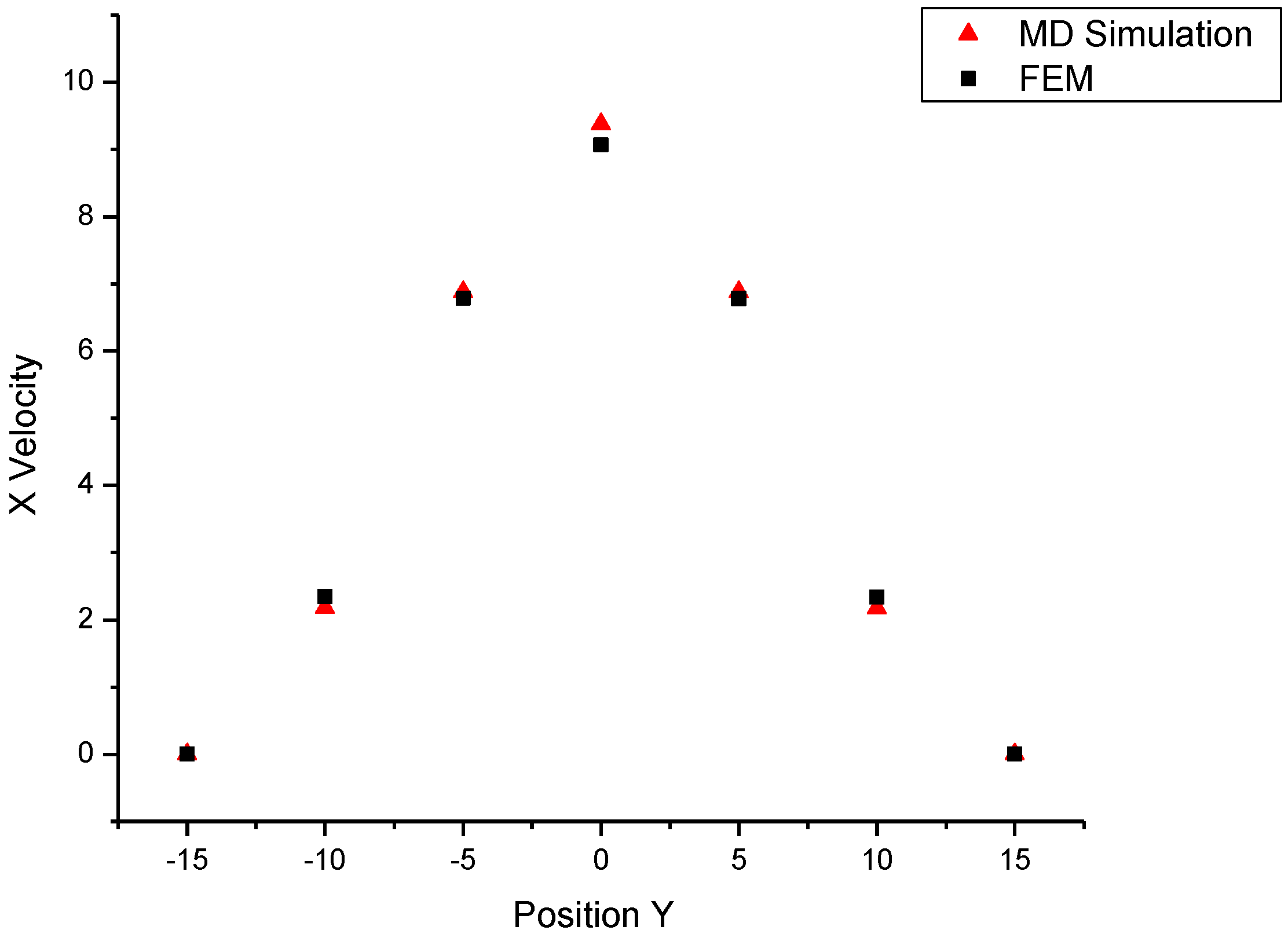
The x-direction velocity profile at position x = 100 is plotted in Figure 3. We find from Figure 3 that the velocities obtained by the MD simulation agree very well with the FEM results. This verification in a simple Poiseuille flow encourages us to apply MDFluid to more complex cases.
Figure 3.
X velocity profile at position x=100 in Case 1

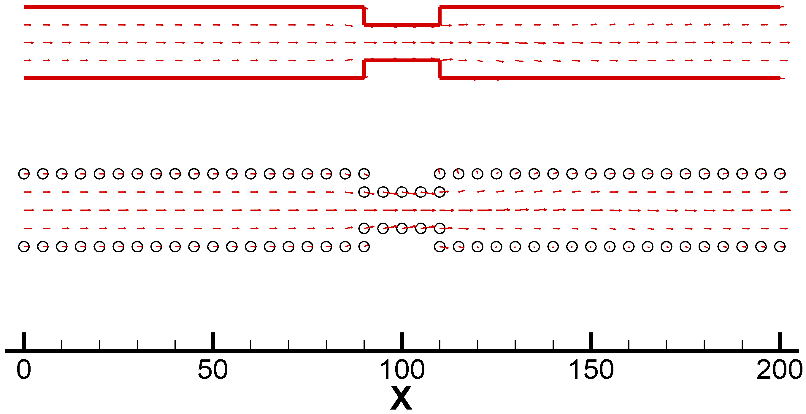
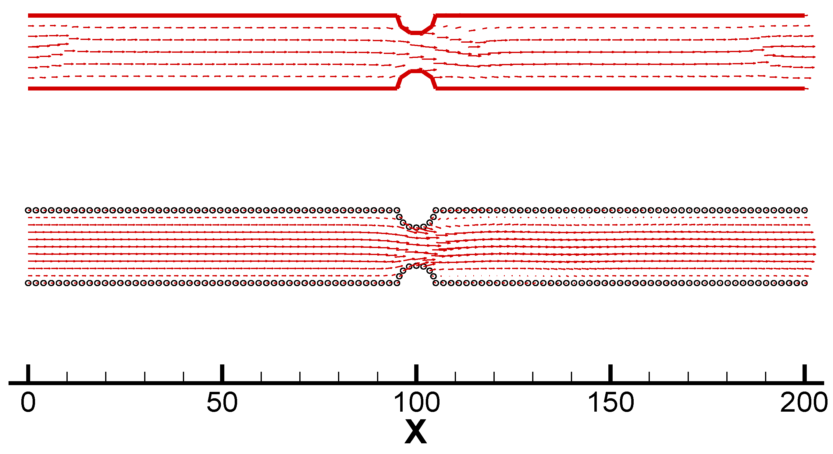
Case 2 is a channel with rectangular concave surfaces in the middle. There are 1600 fluid molecules including 250 wall molecules used in the MD simulation. The strong fluid/wall interaction εfw = 3.5ε is used here. From Figure 4, we can see that the MD simulation has successfully predicted the nano scale vortices near the backward step area (x>110), the size of vortices may be less than 3. In the meantime, the FEM method cannot produce the similar flow phenomena due to the small Reynolds number.
Figure 4.
Velocity vectors by the MD simulation (with circle boundary) and the FEM (with solid line boundary) in Case 2
Figure 4.
Velocity vectors by the MD simulation (with circle boundary) and the FEM (with solid line boundary) in Case 2

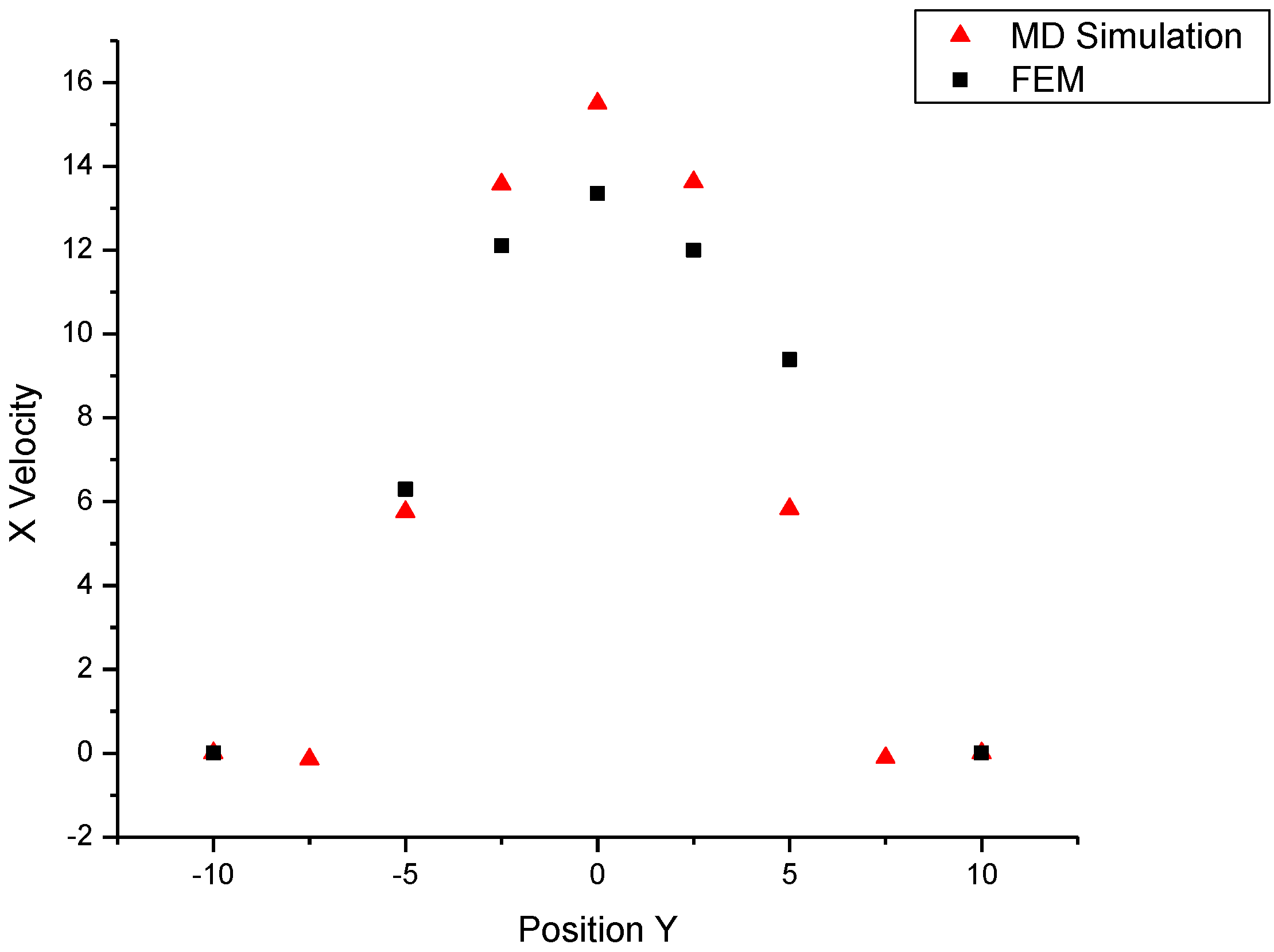
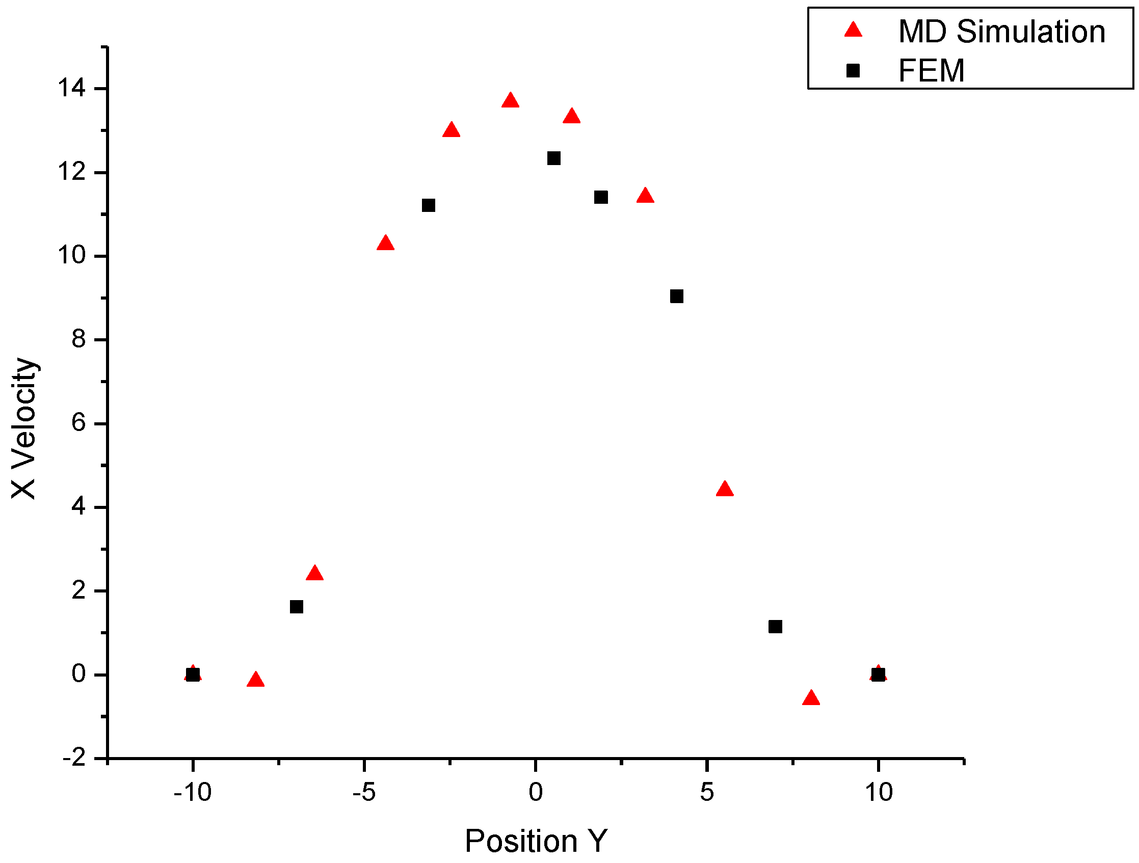
This observation can further be confirmed by the x-direction velocity profile in Figure 5, from which we notice that there are obvious negative velocity molecules near the walls (y = 7.5 and y = -7.5). The reverse momenta induce the generation and development of nano-size vortices under the non-slip boundary conditions.
Figure 5.
X velocity profile at position x=115 in Case 2

Case 3 is a similar channel with convex surfaces. We also set 1600 fluid molecules including 250 wall molecules and strong fluid/wall interaction in the MD simulation. In this case, both predictions on the flow field are analogous (see Figure 6). We cannot see any vortices in both results. One possible reason is that the stream velocities maybe somewhat small compared with those in Case 2 (see Figure 5 and Figure 7).
Figure 6.
Velocity vectors by the MD simulation (with circle boundary) and the FEM (with solid line boundary) in Case 3
Figure 6.
Velocity vectors by the MD simulation (with circle boundary) and the FEM (with solid line boundary) in Case 3

In case 2, the concave surfaces make the middle channel like a contraction nozzle and increase the stream velocity. In this case, on the other hand, the corresponding momentum cannot form vortices in the cavity.
Figure 7.
X velocity profile at position x=100 in Case 3

We next consider the channel with semi-circular surfaces. In order to watch the flow more clearly, we increase the system to 2100 fluid molecules and 360 wall molecules in the course of MD simulation. The Reynolds number is adjusted to 5. The nano vortices reappear in the MD simulation, while the FEM still predicts no any abrupt velocity changes after the middle nozzle area.
Figure 8.
Velocity vectors by the MD simulation (with circle boundary) and the FEM (with solid line boundary) in Case 4
Figure 8.
Velocity vectors by the MD simulation (with circle boundary) and the FEM (with solid line boundary) in Case 4
In Figure 9, we also find the negative velocities near the walls.
Figure 9.
X velocity profile at position x=105 in Case 4
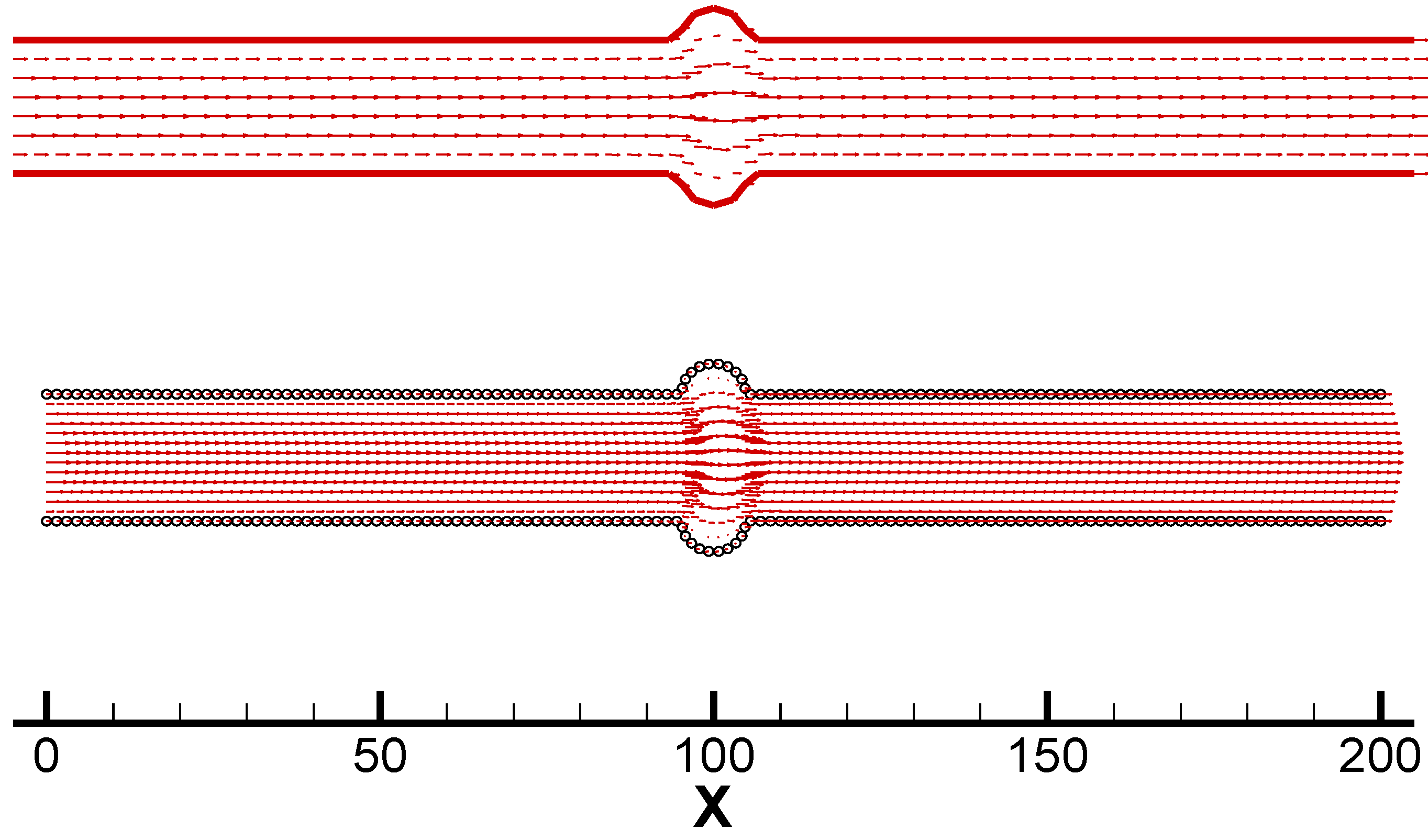
Case 5 is a simple alteration of Case 4, the concave surfaces are replaced by the semi-circular convex surfaces, and all other conditions are kept the same. The vortices occur in the dents due to the accurate simulation by large number of molecules in the MD simulation, while the FEM presents no striking flow attribution (see Figure 10).
Figure 10.
Velocity vectors by the MD simulation (with circle boundary) and the FEM (with solid line boundary) in Case 5
Figure 10.
Velocity vectors by the MD simulation (with circle boundary) and the FEM (with solid line boundary) in Case 5
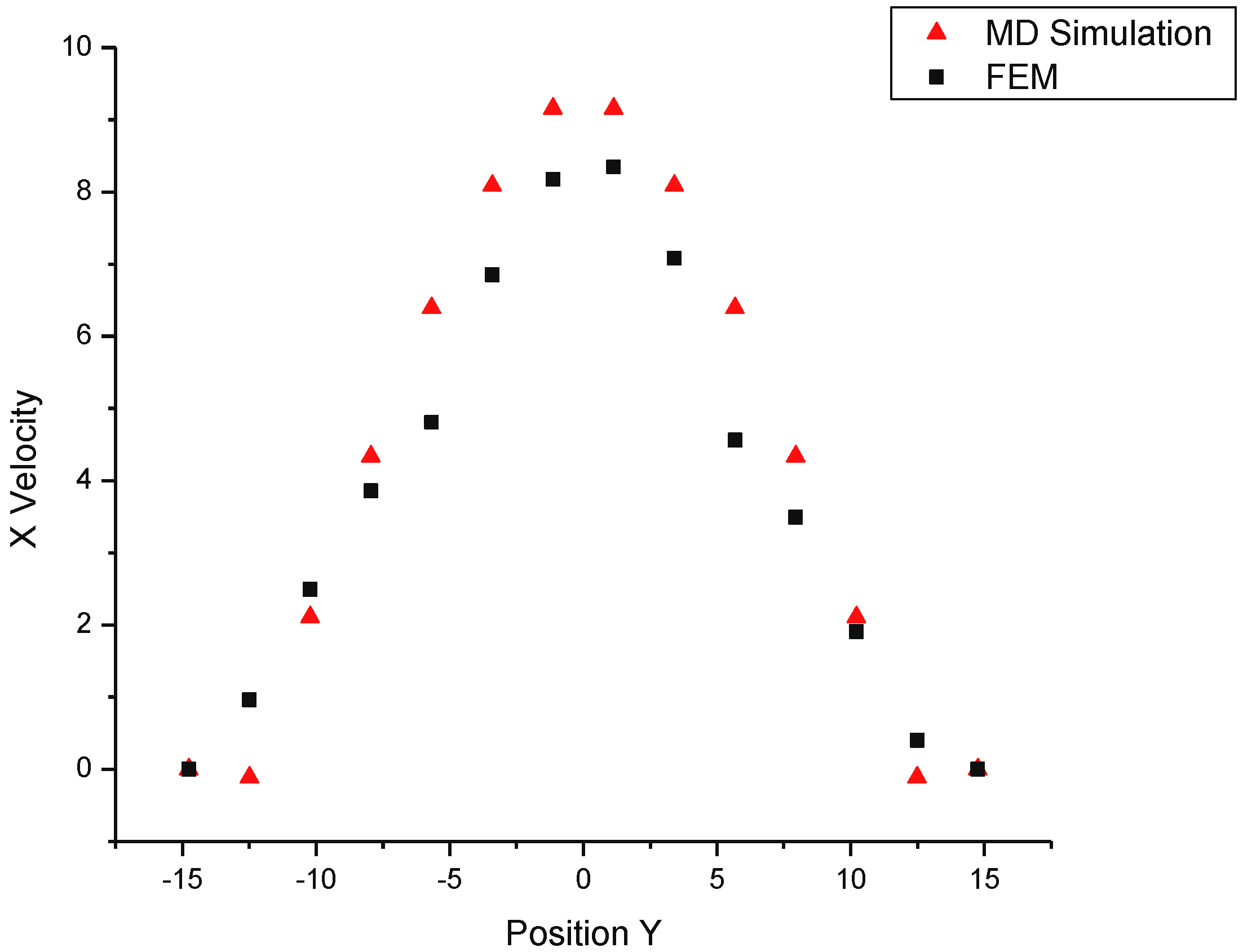
The velocity profile shows negative velocities near the wall region.
Figure 11.
X velocity profile at position x=105 in Case 5
From the above analysis, we find that:
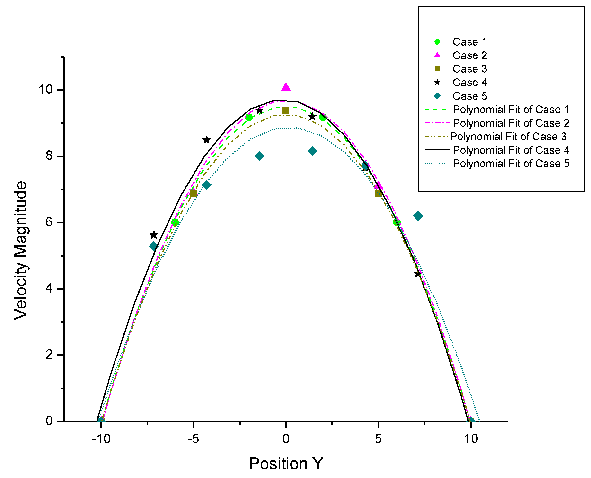
(1) The NS equations and the MD simulations are both applicable for nanochannel flows. The velocity profiles still maintain quadratic for nano Poiseuille flows in the MD simulations (see Figure 12).
Figure 12.
Velocity profiles at x=190

(2) The MD simulation can determine the nano vortices for flows at low Reynolds numbers. The nano vortices may be generated near the walls in complex flows due to the large molecular momenta. In the meantime, the continuum NS equations cannot predict nano flows well near the walls, as they fail to give flow details in the whole field. To this point, we can conclude that large deviations between the NS equations and the MD simulations exist in areas far from the core of the flow.
(3) A guarantee for a good MD simulation is to include as many molecules as possible into the system and to deal appropriately with wall molecules and the boundary conditions.
V. SUMMARY
In this paper we adopt MD simulations to investigate various nanochannel flows at low Reynolds numbers and to present some new interesting results. The WCA potentials with different interaction strength factors are employed for the interaction forces between fluid-fluid and fluid-wall molecules. In order to keep the temperature at the required level, a Gaussian thermostat is introduced in our MD simulations. Comparing the flow fields obtained from the MD simulations with the predictions by the classical NS equations at the same Reynolds number, we find that both results agree with each other qualitatively in the central area of a nanochannel. However, large deviations usually occur in areas far from the core. The nano-size vortices due to the large momenta of molecules in the near-wall region may be found in some complex nanochannel flows. But the traditional NS equations with the no-slip boundary condition at low Reynolds numbers cannot predict the similar phenomenon. It is shown that although the NS equations are still partially valid for nano flows, they fail to give whole details of the flow fields.
Acknowledgements
This research was sponsored by the Hong Kong Research Grant Council under Grant number HKU 7056/01E.
References
- Evans, D. J.; Morris, G. P. Statistical Mechanics of Nonequilibrium Liquids; Academic Press: New York, London, 1990. [Google Scholar]
- Todd, B. D.; Evans, D. J.; Davis, P. J. Phys. Rev. E 1995, 52, 1627–1638.
- Jabbarzadeh, A.; Atkinson, J. D.; Tanner, R. I. J. Non-Newtonian Fluid Mech. 1997, 69, 169–193.
- Travis, K. P.; Todd, B. D.; Evans, D. J. Phys. Rev. E 1997, 55, 4288–4295.
- Fan, X. J.; Phan-Thien, N.; Yong, N. T.; Diao, X. Phys. Fluids 2002, 14, 1146–1153.
- Travis, K. P.; Gubbins, K. E. J. Chem. Phys. 2000, 112, 1984–1994.
- Koplik, J.; Banavar, J. R. Annu. Rev. Fluid Mech. 1995, 27, 257–292.
- Heinbuch, U.; Fischer, J. Physical Review A 1989, 40, 1144–1146.
- Irving, J. H.; Kirkwood, J. G. J. Chem. Phys. 1950, 18, 817–831.
© 2003 by MDPI ( http://www.mdpi.org). Reproduction is permitted for noncommercial purposes.
Share and Cite
MDPI and ACS Style
Mi, X.-B.; Chwang, A.T. Molecular Dynamics Simulations of Nanochannel Flows at Low Reynolds Numbers. Molecules 2003, 8, 193-206. https://doi.org/10.3390/80100193
AMA Style
Mi X-B, Chwang AT. Molecular Dynamics Simulations of Nanochannel Flows at Low Reynolds Numbers. Molecules. 2003; 8(1):193-206. https://doi.org/10.3390/80100193
Chicago/Turabian StyleMi, Xiao-Bing, and Allen T. Chwang. 2003. "Molecular Dynamics Simulations of Nanochannel Flows at Low Reynolds Numbers" Molecules 8, no. 1: 193-206. https://doi.org/10.3390/80100193